EP2653428B1 - Seillängengeber - Google Patents
Seillängengeber Download PDFInfo
- Publication number
- EP2653428B1 EP2653428B1 EP13162691.3A EP13162691A EP2653428B1 EP 2653428 B1 EP2653428 B1 EP 2653428B1 EP 13162691 A EP13162691 A EP 13162691A EP 2653428 B1 EP2653428 B1 EP 2653428B1
- Authority
- EP
- European Patent Office
- Prior art keywords
- rope
- eddy current
- brake
- rope length
- current brake
- Prior art date
- Legal status (The legal status is an assumption and is not a legal conclusion. Google has not performed a legal analysis and makes no representation as to the accuracy of the status listed.)
- Revoked
Links
Images


Classifications
-
- B—PERFORMING OPERATIONS; TRANSPORTING
- B66—HOISTING; LIFTING; HAULING
- B66D—CAPSTANS; WINCHES; TACKLES, e.g. PULLEY BLOCKS; HOISTS
- B66D5/00—Braking or detent devices characterised by application to lifting or hoisting gear, e.g. for controlling the lowering of loads
- B66D5/02—Crane, lift hoist, or winch brakes operating on drums, barrels, or ropes
- B66D5/12—Crane, lift hoist, or winch brakes operating on drums, barrels, or ropes with axial effect
- B66D5/14—Crane, lift hoist, or winch brakes operating on drums, barrels, or ropes with axial effect embodying discs
-
- B—PERFORMING OPERATIONS; TRANSPORTING
- B65—CONVEYING; PACKING; STORING; HANDLING THIN OR FILAMENTARY MATERIAL
- B65H—HANDLING THIN OR FILAMENTARY MATERIAL, e.g. SHEETS, WEBS, CABLES
- B65H61/00—Applications of devices for metering predetermined lengths of running material
-
- B—PERFORMING OPERATIONS; TRANSPORTING
- B65—CONVEYING; PACKING; STORING; HANDLING THIN OR FILAMENTARY MATERIAL
- B65H—HANDLING THIN OR FILAMENTARY MATERIAL, e.g. SHEETS, WEBS, CABLES
- B65H75/00—Storing webs, tapes, or filamentary material, e.g. on reels
- B65H75/02—Cores, formers, supports, or holders for coiled, wound, or folded material, e.g. reels, spindles, bobbins, cop tubes, cans, mandrels or chucks
- B65H75/34—Cores, formers, supports, or holders for coiled, wound, or folded material, e.g. reels, spindles, bobbins, cop tubes, cans, mandrels or chucks specially adapted or mounted for storing and repeatedly paying-out and re-storing lengths of material provided for particular purposes, e.g. anchored hoses, power cables
- B65H75/38—Cores, formers, supports, or holders for coiled, wound, or folded material, e.g. reels, spindles, bobbins, cop tubes, cans, mandrels or chucks specially adapted or mounted for storing and repeatedly paying-out and re-storing lengths of material provided for particular purposes, e.g. anchored hoses, power cables involving the use of a core or former internal to, and supporting, a stored package of material
- B65H75/44—Constructional details
- B65H75/4436—Arrangements for yieldably braking the reel or the material for moderating speed of winding or unwinding
- B65H75/4442—Arrangements for yieldably braking the reel or the material for moderating speed of winding or unwinding acting on the reel
-
- B—PERFORMING OPERATIONS; TRANSPORTING
- B65—CONVEYING; PACKING; STORING; HANDLING THIN OR FILAMENTARY MATERIAL
- B65H—HANDLING THIN OR FILAMENTARY MATERIAL, e.g. SHEETS, WEBS, CABLES
- B65H75/00—Storing webs, tapes, or filamentary material, e.g. on reels
- B65H75/02—Cores, formers, supports, or holders for coiled, wound, or folded material, e.g. reels, spindles, bobbins, cop tubes, cans, mandrels or chucks
- B65H75/34—Cores, formers, supports, or holders for coiled, wound, or folded material, e.g. reels, spindles, bobbins, cop tubes, cans, mandrels or chucks specially adapted or mounted for storing and repeatedly paying-out and re-storing lengths of material provided for particular purposes, e.g. anchored hoses, power cables
- B65H75/38—Cores, formers, supports, or holders for coiled, wound, or folded material, e.g. reels, spindles, bobbins, cop tubes, cans, mandrels or chucks specially adapted or mounted for storing and repeatedly paying-out and re-storing lengths of material provided for particular purposes, e.g. anchored hoses, power cables involving the use of a core or former internal to, and supporting, a stored package of material
- B65H75/44—Constructional details
- B65H75/48—Automatic re-storing devices
-
- B—PERFORMING OPERATIONS; TRANSPORTING
- B66—HOISTING; LIFTING; HAULING
- B66C—CRANES; LOAD-ENGAGING ELEMENTS OR DEVICES FOR CRANES, CAPSTANS, WINCHES, OR TACKLES
- B66C13/00—Other constructional features or details
- B66C13/18—Control systems or devices
- B66C13/46—Position indicators for suspended loads or for crane elements
-
- B—PERFORMING OPERATIONS; TRANSPORTING
- B66—HOISTING; LIFTING; HAULING
- B66D—CAPSTANS; WINCHES; TACKLES, e.g. PULLEY BLOCKS; HOISTS
- B66D5/00—Braking or detent devices characterised by application to lifting or hoisting gear, e.g. for controlling the lowering of loads
- B66D5/02—Crane, lift hoist, or winch brakes operating on drums, barrels, or ropes
- B66D5/24—Operating devices
- B66D5/30—Operating devices electrical
-
- B—PERFORMING OPERATIONS; TRANSPORTING
- B65—CONVEYING; PACKING; STORING; HANDLING THIN OR FILAMENTARY MATERIAL
- B65H—HANDLING THIN OR FILAMENTARY MATERIAL, e.g. SHEETS, WEBS, CABLES
- B65H2701/00—Handled material; Storage means
- B65H2701/30—Handled filamentary material
- B65H2701/35—Ropes, lines
-
- G—PHYSICS
- G01—MEASURING; TESTING
- G01B—MEASURING LENGTH, THICKNESS OR SIMILAR LINEAR DIMENSIONS; MEASURING ANGLES; MEASURING AREAS; MEASURING IRREGULARITIES OF SURFACES OR CONTOURS
- G01B3/00—Measuring instruments characterised by the use of mechanical techniques
- G01B3/10—Measuring tapes
- G01B3/1005—Means for controlling winding or unwinding of tapes
- G01B3/1007—Means for locking
- G01B2003/101—Means for locking acting on the drum
Definitions
- the invention relates to an eddy current brake with a stator and a rotor unit.
- Rope length sensors are used, for example, to measure the distance by which the boom of a crane has been extended.
- the rope length sensor contains a measuring cable, which is wound on a rope drum.
- the cable drum is rotatably mounted in a rope length sensor housing. When the measuring cable is removed from the cable drum, the cable drum rotates. This rotation is measured by a sensor of a rotation rate sensor. It provides a measure of the rope length withdrawn from the rope drum ( DE 88 01 109.7 U ; DE 297 07 252.6 U ; DE 199 25 364 C2 ).
- the rope length sensor is fastened in a reference point and the free end of the measuring rope is attached to a part moving with respect to the reference point.
- the withdrawn rope length then provides the movement of the moving part.
- the rope length sensor can be attached to a stationary part of a crane and the end of the measuring cable attached to the end of a crane jib. Then the extension length of the crane boom can be monitored by the signal of the rope length sensor.
- the cable drum is under the influence of a restoring torque, e.g. can be applied by a spring motor. The measuring cable is pulled off against this restoring moment.
- the measuring cable is guided out of the housing of the cable length sensor with low friction via a cable guide.
- This cable guide is usually designed so that the rope can also be removed at an angle from the housing.
- Such cable guides can be a roller guide with two mutually crossed pairs of arranged around the measuring cable guide rollers ( DE 20 2004 007 424.9 U ) exhibit.
- the cable guide can also be formed by a provided with a guide bore body which is mounted on all sides pivotally in a spherical bearing surface.
- eddy current brakes There are also known eddy current brakes.
- a braking torque is generated by a relative speed between a stationary and a moving object.
- the eddy current brake operates without contact and thus wear-free. Physically, an electrically conductive disk is moved in a magnetic field, thereby generating voltages due to eddy currents, the in turn generate a magnetic field which opposes the generating field. The moving object is thereby slowed down.
- the metal plate becomes the ohmic consumer, which converts the kinetic energy into heat.
- the strength of the braking effect depends, inter alia, on the conductivity of the metal plate, the relative velocity between the moving objects, the distance between the magnetic field and the metal disc, the direction of the magnetic field.
- the braking torque is almost linear to the speed.
- the DE 602005002743 T2 a rope winding system for winding and unwinding a steel cable of a crane.
- the rope winding system comprises a cable drum on which the steel cable is wound in several layers.
- a magnetic system designed as an eddy current brake is arranged such that it generates a magnetic field about a cable section of the steel cable whose magnetic flux is deflected by a movement of the steel cable in such a way that the steel cable is braked.
- This eddy current brake acts to decelerate directly on the rope.
- EP1014032A discloses a rope length sensor according to the preamble of claim 1.
- the object of the invention is therefore to eliminate disadvantages of the prior art and to provide a rope length sensor, in which the rope can be braked controlled. According to the invention the object is achieved by a rope length sensor according to claim 1
- the invention is based on the principle to provide an effective brake for a rope length sensor, which brakes the cable drum and thus the rope in case of malfunction or incorrect operation. Due to the eddy current brake, the cable drum can be decelerated effectively and controlled.
- the eddy current brake is also characterized by its freedom from wear. Since there is no friction in the eddy current brake, no mechanical wear takes place accordingly. The eddy current brake is thus very easy to maintain and particularly effective.
- a braking torque is generated by a relative speed between the stationary and the moving object. Physically, an electrically conductive rotor is moved in a magnetic field.
- the stator unit is disc-shaped, on which, as a first variant, mutually poled permanent magnets are arranged in a ring shape.
- This stator unit can be realized in the simplest way.
- the permanent magnets need only be arranged in the correct arrangement, ie annular, on the stator unit.
- the disc-shaped stator unit is provided as a second variant with sector-shaped, multi-pole ring magnets.
- This alternative of the stator unit is particularly effective. As a result, a particularly effective braking effect is achieved.
- the disk-shaped stator unit of the eddy current brake is connected to a housing and / or frame flange.
- the stator unit can in this way be very easily connected to the housing or to the frame, ie bolted, in order to obtain sufficient strength, which is required for such an eddy current brake.
- An embodiment of the rope length sensor according to the invention also results from the fact that the rotor unit includes a brake disc which is provided on the cable drum, wherein the brake disc is arranged perpendicular to the magnetic field lines of the permanent magnets.
- the brake disc is optimally arranged to the permanent magnets, so that a maximum braking power can be achieved.
- An embodiment of the brake disc of the rope length sensor according to the invention is also obtained by comprising copper disc and a return plate made of soft iron. Copper is a particularly good conductor. Therefore, this material is particularly well suited to the brake disc to generate eddy currents there. These eddy currents finally generate the magnetic field, which counteracts the magnetic field of the permanent magnets.
- stator unit and the rotor unit can of course also be constructed in reverse, which is not part of the invention
- the rotor then contains the permanent or ring magnet arrangement.
- the brake disc is provided in this case according statically relative to the housing or frame. With the eddy current brake, only the relative movement of the brake disc relative to the magnets is important.
- the eddy current brake is integrated into the cable pull mechanism in the rope length sensor according to the invention. This measure ensures that the eddy current brake is optimally integrated into the rope length sensor for braking.
- the eddy current brake engages in a malfunction or a faulty operation directly in the cable pull mechanism, so that damage, for example, by a snapping rope, can be prevented.
- the distance between the brake disc and the disk-shaped stator unit is provided adjustable in a preferred embodiment of the rope length sensor according to the invention.
- the distance between the brake disc and the permanent magnets has a direct influence on the braking effect.
- the effect increases with decreasing distance.
- a regulation of the braking torque via an external adjustment option for changing the air gap can thus be made possible.
- an eddy current brake which is not part of the invention, with a stator and a rotor unit, this is formed on a rotatably mounted shaft of a cable drum of the rope length sensor coupled.
- a rope length sensor with an eddy current brake can be retrofitted quickly. So each rope length sensor, which has a suitable coupling option, can be quickly retrofitted with an eddy current brake.
- Fig. 1 is called a rope length transmitter at 10.
- the rope length sensor 10 is shown schematically in a perspective exploded view.
- the rope length sensor 10 includes an eddy current brake 12, which is integrated in a housing 14 of the rope length sensor 10.
- a measuring cable 18 is wound.
- a spring-operated return actuator 20 is also provided (see also Fig. 3 ).
- the measuring cable 18 is unwound against the spring force of the return drive 20.
- the return drive 20 rewinds the measuring cable onto the cable drum 16.
- the cable drum 16 is rotatably mounted in the housing 14 with a shaft 22.
- annular return plate 26 of the eddy current brake 12 is fixed statically in the interior.
- the annular return plate 26 is dimensioned in the present embodiment, that it fits into the cable drum 16 (see also Fig. 2 ).
- On the return plate 26 are permanent magnets 28, 30th arranged in a ring.
- the permanent magnets 28 alternate in polarity with the permanent magnets 30.
- the permanent magnets 28, 30 are round-block magnets that are axially fixed to the annular return plate 26.
- the return plate 26, together with the annularly arranged permanent magnets 28, 30, forms a stator unit 32 of the eddy current brake 12, which is fastened to a receiving board 33.
- a circular brake disc 36 is flanged on a flange 34 of the cable drum 16.
- the brake disk 36 comprises an annular return plate 38 made of soft iron.
- the part 40 of the brake disk 36 facing the permanent magnets 28, 30 is made of a good conductive material, such as copper.
- a cap 42 closes off the end face 24 of the cable drum 16.
- Fig. 2 shows in a side view with a partial section of the rope length sensor 10 with integrated eddy current brake 12 corresponding to that of Fig.1 ,
- the cap 42 and the brake disc 36 are shown broken away in about half, so that here the stator 32 is visible.
- the stator unit 32 is disposed within the cable drum 16 of the rope length sensor 10. For this purpose it is fixed with screws 44 on the receiving board.
- the cap 42 is screwed to the flange 34 with screws 46 in order to protect the entire mechanism of the rope length sensor 10 against external influences.
- Fig. 3 shows a schematic longitudinal section of the rope length sensor 10 with the integrated eddy current brake 12.
- This rope length sensor 10 corresponds to the figures according to Fig.1 respectively.
- Fig. 2 For the same components, therefore, corresponding reference numerals are used in each case.
- the measuring cable 18 is rolled up. The measuring cable 18 can be pulled off against the spring force of the return drive 20.
- the cable drum 16 is seated firmly on the shaft 22, which is rotatably mounted in bearings 48 in the housing 14.
- the cable drum 16 rotates with the shaft 22 during removal and winding of the measuring cable 18.
- the shaft 22 of the cable length sensor 10 protrudes into a rotation rate sensor 50, which determines the revolutions of the shaft 22 and thus of the cable drum 16.
- the rotation rate sensor 50 supplies signals and / or values which correspond to the rotation of the cable drum 16. From the scope of the cable drum 16 Thus, the length of the unwound or wound measuring cable 18 can be determined by calculation.
- the eddy current brake 12 is located on the opposite side of the yaw rate sensor 50.
- the circular brake disc 36 is flanged.
- the components of the brake disk 36 are clearly visible: on the one hand, the annular return plate 38 made of soft iron and, on the other hand, part 40 of the brake disk 36 made of copper.
- the cap 42 closes the end face 24 of the cable drum 16.
- the brake disc 36 forms a rotor unit 52 which rotates with the shaft 22 and the cap 42.
- the brake disk 36 is arranged perpendicular to the magnetic fields of the permanent magnets 28, 30. Between the stator unit 32 and the rotor unit 52 there is an air gap 54. This air gap 54 is designed to be variable in that the distance between the rotor unit 52 and the stator unit 32 is adjustable. Thus, the braking effect can be changed.
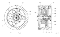
- Fig. 4 shows in a side view with partial section a dockable eddy current brake 100 for a rope length sensor.
- the eddy current brake 100 has a housing 102 in which a brake disk 104 is rotatably mounted with a shaft 106.
- the shaft 106 is fixedly connected by means of a coupling 105 to the shaft of a rope length sensor (see Fig. 5 ).
- the coupling 105 consists of flanges 107.
- the shaft of the rope length sensor can also be used by itself. This then projects, for example, out of the housing 102 of the rope length sensor and is guided into the housing 102 of the dockable eddy current brake 100.
- the shaft 106 is fixedly connected to the brake disk 104.
- the brake disk 104 consists of two components, a return plate 108 made of soft iron and an annular copper disk 110 (see Fig. 5 ).
- the brake disk 104 forms the rotor unit 109 of the eddy current brake 100.
- the rotor unit 109 is in Fig. 4 not shown and only in Fig. 5 visible, noticeable.
- a partial view of a stator unit 111 is shown.
- the stator unit 111 is formed by permanent magnets 112, 114 and a return plate 116 made of soft iron.
- the stator unit 111 is on a Holding plate 133 fixed.
- the permanent magnets 112, 114 are arranged annularly on the return plate 116.
- the permanent magnets 112, 114 are round-block magnets that are axially mounted on the return plate 116. In this case, the polarity of the permanent magnets 112 changes with the polarity of the permanent magnets 114.
- Fig. 5 shows a longitudinal section of the eddy current brake 100 according to the invention Fig. 4 ,
- the eddy current brake 100 is located in the housing 102.
- the shaft 106 is guided transversely through the housing 102 and rotatably supported therein.
- the clutch 105 With the clutch 105, the eddy current brake 100 can be docked to the rope length sensor.
- a rotation of the shaft of the cable length sensor is transmitted via the coupling 105 directly to the shaft 106, on which the brake disk 104 is firmly seated.
- the stator unit 111 is fixed inside the housing 102.
- the rotating brake disk 104 is largely perpendicular to the magnetic field lines of the permanent magnets 112, 114.
- the brake disk 104 consists of the annular return plate 108 made of soft iron and one of the annular copper disk 110.
- the permanent magnets 112 and 114 are seated on the return plate 116.
- Fig. 6 shows in a simplified schematic diagram a section of an eddy current brake 100, as for example. According to Fig. 4 respectively. Fig. 5 is shown.
- the brake disk 104 is mounted on the rotatably mounted shaft 106. This forms the rotor unit 109 of the eddy current brake 100.
- the brake disk 104 is arranged at a distance L from the annularly arranged permanent magnets 112, 114 of the stator unit 111.
- the annular return plate 116 can also be seen, on which the permanent magnets 112, 114 designed as round block magnets are fastened.
- the operation is as follows based on the Fig. 6 briefly explained:
- the braking torque is generated by the relative speed between the stator 111 standing and the moving rotor unit 109.
- the eddy current brake 100 operates contactless and thus wear-free.
- the electrically conductive brake disk 104 is moved in the magnetic field of the permanent magnets 112, 114. In this case, voltages are generated due to eddy currents. These in turn generate a magnetic field which counteracts the generating field.
- the moving brake disc 104 is thereby braked.
- the kinetic energy is thereby converted into heat.
- the strength of the braking effect is dependent in particular on the conductivity of the brake disk 104.
- the relative speed between the moving rotor unit 109 and the stator unit 111 also plays a role in addition to the distance L between the magnetic field of the permanent magnets 112, 114 and the brake disk. Furthermore, the direction of the magnetic field has an influence on the braking effect. The braking torque is almost linear to the rotational speed of the brake disk 104.
- the brake disc 36 rotates at the appropriate speed in the magnetic field of the statically arranged permanent magnets 28, 30.
- eddy currents are generated, which counteracting Generate magnetic field, which brakes the brake disc 26 together with the cable drum 16 controlled.
Description
- Die Erfindung betrifft einen Seillängengeber umfassend
- a) ein Gehäuse und/oder Rahmen,
- b) eine in dem Gehäuse und/oder Rahmen drehbar gelagerten Seiltrommel, auf welcher ein Messseil auf- und abwickelbar vorgesehen ist,
- c) einen Drehratengeber, der die die Anzahl der Drehungen der Seiltrommel erfasst und
- d) einen Rückstellantrieb für die Seiltrommel, welcher das abgewickelte Messseil wieder auf die Seiltrommel aufwickelt.
- Weiterhin betrifft die Erfindung eine Wirbelstrombremse mit einer Statoreinheit und einer Rotoreinheit.
- Seillängengeber dienen beispielsweise zur Messung der Strecke, um welche der Ausleger eines Krans ausgefahren worden ist. Der Seillängengeber enthält ein Messseil, das auf eine Seiltrommel aufgewickelt ist. Die Seiltrommel ist in einem Seillängengeber-Gehäuse drehbar gelagert. Wenn das Messseil von der Seiltrommel abgezogen wird, dreht sich die Seiltrommel. Diese Drehung wird durch einen Sensor eines Drehratengebers gemessen. Sie liefert ein Maß für die von der Seiltrommel abgezogene Seillänge (
DE 88 01 109.7 U ;DE 297 07 252.6 U ;DE 199 25 364 C2 ). - Der Seillängengeber wird in einem Referenzpunkt befestigt und das frei Ende des Messseils an einem gegenüber dem Referenzpunkt bewegten Teil angebracht. die abgezogene Seillänge liefert dann die Bewegung des bewegten Teils. Beispielsweise kann der Seillängengeber an einem stationären Teil eines Krans befestigt und das Ende des Messseils am Ende eines Kranauslegers angebracht sein. Dann kann durch das Signal des Seillängengebers die Ausfahrlänge des Kranauslegers überwacht werden. Die Seiltrommel steht unter dem Einfluss eines Rückstellmomentes, das z.B. von einem Federmotor aufgebracht werden kann. Das Messseil wird gegen dieses Rückstellmoment abgezogen.
- Das Messseil wird über eine Seilführung reibungsarm aus dem Gehäuse des Seillängengebers herausgeführt. Diese Seilführung ist üblicherweise so ausgeführt, dass das Seil auch schräg aus dem Gehäuse abgezogen werden kann. Solche Seilführungen können eine Rollenführung mit zwei zueinander gekreuzt angeordneten Paaren von um das Messseil herum angeordneten Führungsrollen (
DE 20 2004 007 424,9 U - Es sind ferner Wirbelstrombremsen bekannt. Bei der Wirbelstrombremse wird ein Bremsmoment durch eine Relativgeschwindigkeit zwischen einem stehenden und einem sich bewegenden Objekt erzeugt. Die Wirbelstrombremse arbeitet berührungslos und somit verschleißfrei. Physikalisch wird eine elektrisch leitende Scheibe in einem Magnetfeld bewegt, dabei werden Spannungen aufgrund von Wirbelströmen erzeugt, die ihrerseits ein Magnetfeld erzeugen, welches dem erzeugenden Feld entgegenwirkt. Das bewegte Objekt wird dadurch abgebremst. Dabei wird die Metallplatte zum Ohmschen Verbraucher, welcher die Bewegungsenergie in Wärme umsetzt. Die Stärke der Bremswirkung ist u.a. abhängig von der Leitfähigkeit der Metallplatte, der Relativgeschwindigkeit zwischen den bewegten Objekten, dem Abstand zwischen Magnetfeld und Metallscheibe, Richtung des Magnetfeldes. Das Bremsmoment ist nahezu linear zur Drehzahl.
- Es sind ferner Wirbelstrombremsen bei Seilaufwicklungen bekannt. So offenbart beispielsweise die
DE 602005002743 T2 ein Seilwickelsystem zum Auf- und Abwickeln eines Stahlseils eines Kranes. Das Seilwickelsystem umfasst eine Seiltrommel, auf die das Stahlseil in mehreren Lagen aufgewickelt ist. Ein als Wirbelstrombremse ausgebildetes Magnetsystem ist derart angeordnet, dass es um einen Seilabschnitt des Stahlseils ein Magnetfeld erzeugt, dessen magnetischer Fluss durch eine Bewegung des Stahlseils derartig ablenkt wird, dass das Stahlseil abgebremst wird. Diese Wirbelstrombremse wirkt zum Abbremsen dabei unmittelbar auf das Seil. - Bei den bekannten Seillängengebern tritt häufig das Problem auf, dass bei Seilriss oder bei Fehlbedienung des Seillängengebers, indem das Messseil schnappen gelassen wird. Eine Beschädigung des Geräts ist die Folge. Nicht selten kommt es dabei zum Totalausfall des Seillängengebers. Das Gerät muss dann ausgetauscht oder einer Totalreparatur unterzogen werden.
-
EP1014032A offenbart einen Seillängengeber gemäß dem Oberbegriff des Anspruchs 1. - Aufgabe der Erfindung ist es daher, Nachteile des Standes der Technik zu beseitigen und einen Seillängengeber zu schaffen, bei dem das Seil kontrolliert abgebremst werden kann. Erfindungsgemäß wird die Aufgabe durch einen Seillängengeber gemäß Anspruch 1 gelöst
- Die Erfindung beruht auf dem Prinzip eine wirksame Bremse für einen Seillängengeber vorzusehen, der die Seiltrommel und damit auch das Seil bei einer Fehlfunktion bzw. Fehlbedienung abbremst. Durch die Wirbelstrombremse lässt sich die Seiltrommel wirksam und kontrolliert abbremsen. Die Wirbelstrombremse zeichnet sich zudem durch ihre Verschleißfreiheit aus. Da es bei der Wirbelstrombremse zu keiner Reibung kommt, findet dementsprechend auch kein mechanischer Verschleiß statt. Die Wirbelstrombremse ist somit sehr wartungsfreundlich und besonders wirksam. Bei der Wirbelstrombremse wird ein Bremsmoment durch eine Relativgeschwindigkeit zwischen dem stehenden und dem sich bewegenden Objekt erzeugt. Physikalisch wird ein elektrisch leitender Rotor in einem Magnetfeld bewegt. Dabei werden Spannungen aufgrund von Wirbelströmen erzeugt, die ihrerseits ein Magnetfeld erzeugen, welches dem erzeugenden Feld entgegenwirkt. Das bewegte Objekt wird dadurch abgebremst. Als vorteilhafte Ausgestaltung der Erfindung hat sich erwiesen, wenn die Wirbelstrombremse im Gehäuse und/oder Rahmen des Seillängengebers integriert ist. Dadurch wird eine kompakte Bauweise erreicht, die auch auf engem Raum eingesetzt werden kann. Die Integration der Wirbelstrombremse in dem Gehäuse bewirkt zudem, dass diese nicht verschmutzt. Häufig werden solche Bauteile nämlich bei Kränen, welche auf Baustellen verwendet werden, genutzt. Die Wirbelstrombremse wird somit durch das Gehäuse bzw. den Rahmen auch vor anderen äußeren Einflüssen geschützt.
- In einer Ausbildung des erfindungsgemäßen Seillängengebers ist die Statoreinheit scheibenförmig ausgebildet, auf welcher als eine erste Variante wechselseitig gepolte Permanentmagnete ringförmig angeordnet sind. Diese Statoreinheit lässt sich auf einfachste Art realisieren. Die Permanentmagneten müssen nur in der richtigen Anordnung, d.h. ringförmig, auf der Statoreinheit angeordnet werden.
- In einer weiteren Ausgestaltung des erfindungsgemäßen Seillängengebers ist die scheibenförmige Statoreinheit als eine zweite Variante mit sektorförmig angeordneten, mehrpoligen Ringmagneten vorgesehen. Diese Alternative der Statoreinheit ist besonders wirkungsvoll. Hierdurch wird eine besonders effektive Bremswirkung erreicht.
- Vorzugsweise ist bei einer Ausbildung des erfindungsgemäßen Seillängengebers die scheibenförmige Statoreinheit der Wirbelstrombremse mit einem Gehäuse- und/oder Rahmenflansch verbunden. Die Statoreinheit kann auf diese Weise sehr einfach mit dem Gehäuse bzw. mit dem Rahmen verbunden, d.h. verschraubt werden, um ausreichende Festigkeit, welche für eine solche Wirbelstrombremse erforderlich ist, zu erhalten.
Eine Ausgestaltung des erfindungsgemäßen Seillängengebers ergibt sich ferner dadurch, dass die Rotereinheit eine Bremsscheibe enthält, welche an der Seiltrommel vorgesehen ist, wobei die Bremsscheibe senkrecht zu den Magnetfeldlinien der Permanentmagnete angeordnet ist. Damit ist die Bremsscheibe optimal zu den Permanentmagneten angeordnet, so dass eine sich maximale Bremsleistung erzielen lässt. Eine Ausführung der Bremsscheibe des erfindungsgemäßen Seillängengebers erhält man zudem dadurch, dass sie Kupferscheibe und eine Rückschlussplatte aus Weicheisen umfasst. Kupfer ist ein besonders guter Leiter. Daher eignet sich dieses Material besonders gut auf der Bremsscheibe, um dort Wirbelströme zu erzeugen. Diese Wirbelströme generieren schließlich das Magnetfeld, welches dem Magnetfeld der Permanentmagnete entgegenwirkt. - Grundsätzlich kann die Anordnung von Statoreinheit und Rotoreinheit selbstverständlich auch umgekehrt aufgebaut sein, was nicht Teil der Erfindung ist
- Der Rotor enthält dann somit die Permanent- bzw. Ringmagnetenanordnung. Die Bremsscheibe ist in diesem Fall entsprechend statisch gegenüber dem Gehäuse bzw. Rahmen vorgesehen. Bei der Wirbelstrombremse kommt es nur auf die relative Bewegung der Bremsscheibe gegenüber den Magneten an.
- In einem weiteren bevorzugten Aspekt ist bei dem erfindungsgemäßen Seillängengeber die Wirbelstrombremse in die Seilzugmechanik integriert. Mit dieser Maßnahme wird erreicht, dass die Wirbelstrombremse bestmöglich in den Seillängengeber zum Abbremsen integriert ist. Die Wirbelstrombremse greift bei einer Fehlfunktion oder einer Fehlbedienung unmittelbar in die Seilzugmechanik ein, so dass ein Schaden beispielsweise durch ein schnappendes Seil, verhindert werden kann.
- Um die Wirkung der Wirbelstrombremse variabel zu halten, ist in einer bevorzugten Ausgestaltung des erfindungsgemäßen Seillängengebers der Abstand zwischen der Bremsscheibe und der scheibenförmigen Statoreinheit einstellbar vorgesehen. Der Abstand der Bremsscheibe zu den Permanentmagneten hat einen unmittelbaren Einfluss auf die Bremswirkung. Je größer der Abstand der Bremsscheibe ist, desto geringer ist auch die Bremswirkung. Umgekehrt steigt die Wirkung mit Abnahme des Abstands. Eine Regulierung des Bremsmoments über eine äußere Einstellmöglichkeit zur Veränderung des Luftspalts lässt sich so ermöglichen.
- Bei einer Ausgestaltung einer Wirbelstrombremse, die nicht Teil der Erfindung ist, mit einer Stator- und einer Rotoreinheit, ist diese an einer drehbar gelagerten Welle einer Seiltrommel des Seillängengebers ankoppelbar ausgebildet. Auf diese Weise kann ein Seillängengeber mit einer Wirbelstrombremse schnell nachgerüstet werden. So kann jeder Seillängengeber, der über eine geeignete Kupplungsmöglichkeit verfügt, schnell mit einer Wirbelstrombremse nachgerüstet werden.
- Ausgestaltungen und Vorteile der Erfindung ergeben sich aus dem Gegenstand der Unteransprüche. Ein Ausführungsbeispiel ist nachstehend unter Bezugnahme auf die beigefügten Zeichnungen näher erläutert.
-
- Fig. 1
- zeigt in einer perspektivischen Explosionszeichnung einen erfindungsgemäßen Seillängengeber mit integrierter Wirbelstrombremse.
- Fig. 2
- zeigt in einer Seitenansicht mit teilweisem Schnitt einen erfindungsgemäßen Seillängengeber mit integrierter Wirbelstrombremse gemäß
Fig.1 . - Fig. 3
- zeigt einen Schnitt eines erfindungsgemäßen Seillängengebers mit integrierter Wirbelstrombremse gemäß
Fig.1 bzw.Fig. 2 . - Fig. 4
- zeigt in einer Seitenansicht mit teilweisem Schnitt eine Wirbelstrombremse für einen Seillängengeber.
- Fig. 5
- zeigt einen Schnitt eine Wirbelstrombremse gemäß
Fig. 4 . - Fig. 6
- zeigt in einer Prinzipskizze einen Schnitt eine Wirbelstrombremse gemäß
Fig. 4 bzw.Fig. 5 . - In
Fig. 1 wird mit 10 ein Seillängengeber bezeichnet. Der Seillängengeber 10 ist in einer perspektivischen Explosionszeichnung schematisch dargestellt. Der Seillängengeber 10 enthält eine Wirbelstrombremse 12, welche in ein Gehäuse 14 des Seillängengebers 10 integriert ist. Auf einer Seiltrommel 16 ist ein Messseil 18 aufgewickelt. In dem Gehäuse 12 des Seillängengebers 10 ist ferner ein federbetriebener Rückstellantrieb 20 vorgesehen (siehe auchFig. 3 ). Das Messseil 18 wird gegen die Federkraft des Rückstellantriebs 20 abgewickelt. Der Rückstellantrieb 20 wickelt das Messseil wieder auf die Seiltrommel 16 auf. Die Seiltrommel 16 ist in dem Gehäuse 14 mit einer Welle 22 drehbar gelagert. - An Stirnseite 24 der Seiltrommel 16 ist im Inneren eine ringförmige Rückschlussplatte 26 der Wirbelstrombremse 12 statisch befestigt. Die ringförmige Rückschlussplatte 26 ist im vorliegenden Ausführungsbeispiel so dimensioniert, dass sie in die Seiltrommel 16 passt (vgl. auch
Fig. 2 ). An der Rückschlussplatte 26 sind Permanentmagnete 28, 30 ringförmig angeordnet. Die Permanentmagnete 28 wechseln sich in der Polarität mit den Permanentmagneten 30 ab. Bei den Permanentmagneten 28, 30 handelt es sich um Rundblockmagneten, die axial an der ringförmigen Rückschlussplatte 26 befestigt sind. Die Rückschlussplatte 26 bildet mit den daran angeordneten ringförmig angeordneten Permanentmagneten 28, 30 eine Statoreinheit 32 der Wirbelstrombremse 12, welche an einer Aufnahmeplatine 33 befestigt ist. - An einem Flansch 34 der Seiltrommel 16 ist eine kreisförmige Bremsscheibe 36 angeflanscht. Die Bremsscheibe 36 umfasst eine ringförmige Rückschlussplatte 38 aus Weicheisen. Der zu den Permanentmagneten 28, 30 zeigende Teil 40 der Bremsscheibe 36 besteht aus gut leitendem Material, wie Kupfer. Eine Abdeckkappe 42 schließt die Stirnseite 24 der Seiltrommel 16 ab.
-
Fig. 2 zeigt in einer Seitenansicht mit teilweisem Schnitt den Seillängengeber 10 mit integrierter Wirbelstrombremse 12 entsprechend dem vonFig.1 . Die Abdeckkappe 42 und die Bremsscheibe 36 sind in etwa zur Hälfte weggebrochen dargestellt, so dass hier die Statoreinheit 32 sichtbar wird. Die Statoreinheit 32 ist innerhalb der Seiltrommel 16 des Seillängengebers 10 angeordnet. Dazu ist sie mit Schrauben 44 an der Aufnahmeplatine fixiert. Die Abdeckkappe 42 ist mit Schrauben 46 an dem Flansch 34 verschraubt, um die ganze Mechanik des Seillängengebers 10 vor äußeren Einflüssen zu schützen. -
Fig. 3 zeigt einen schematischen Längsschnitt des Seillängengebers 10 mit der integrierten Wirbelstrombremse 12. Dieser Seillängengeber 10 entspricht den Abbildungen gemäßFig.1 bzw.Fig. 2 . Für gleiche Bestandteile werden daher auch jeweils sich entsprechende Bezugszeichen verwendet. Auf der Seiltrommel 16 ist das Messseil 18 aufgerollt. Das Messseil 18 kann gegen die Federkraft des Rückstellantriebs 20 abgezogen werden. Die Seiltrommel 16 sitzt fest auf der Welle 22, welche drehbar in Lagern 48 im Gehäuse 14 gelagert ist. Die Seiltrommel 16 rotiert mit der Welle 22 beim Abziehen und Aufwickeln des Messseils 18. Die Welle 22 des Seillängengebers 10 ragt in einen Drehratengeber 50, welcher die Umdrehungen der Welle 22 und damit der Seiltrommel 16 ermittelt. Der Drehratengeber 50 liefert Signale und/oder Werte, welche der Umdrehung der Seiltrommel 16 entsprechen. Aus dem Umfang der Seiltrommel 16 kann so die Länge des abgewickelten bzw. aufgewickelten Messseils 18 rechnerisch ermittelt werden. - Die Wirbelstrombremse 12 befindet sich auf der dem Drehratengeber 50 gegenüberliegenden Seite. An dem Flansch 34 der Seiltrommel 16 ist die kreisförmige Bremsscheibe 36 angeflanscht. Im Schnitt sind die Komponenten der Bremsscheibe 36 gut zu sehen: Einerseits die ringförmige Rückschlussplatte 38 aus Weicheisen und andererseits Teil 40 der Bremsscheibe 36 aus Kupfer. Die Abdeckkappe 42 schließt die Stirnseite 24 der Seiltrommel 16 ab. Die Bremsscheibe 36 bildet eine Rotoreinheit 52, welche sich mit der Welle 22 und der Abdeckkappe 42 dreht. Die Bremsscheibe 36 ist senkrecht zu den Magnetfeldern der Permanentmagnete 28, 30 angeordnet. Zwischen Statoreinheit 32 und der Rotoreinheit 52 besteht ein Luftspalt 54. Dieser Luftspalt 54 ist variable ausgestaltet, indem der Abstand zwischen der Rotoreinheit 52 und der Statoreinheit 32 einstellbar ausgebildet ist. Damit kann die Bremswirkung verändert werden.
-
Fig. 4 zeigt in einer Seitenansicht mit teilweisem Schnitt eine andockbare Wirbelstrombremse 100 für einen Seillängengeber. Die Wirbelstrombremse 100 weist ein Gehäuse 102 auf, in dem eine Bremsscheibe 104 mit einer Welle 106 drehbar gelagert ist. Die Welle 106 ist mittels einer Kupplung 105 mit der Welle eines Seillängengebers fest verbunden (sieheFig. 5 ). Im vorliegenden Ausführungsbeispiel besteht die Kupplung 105 aus Flanschen 107. Prinzipiell kann die Welle des Seillängengebers auch selbst verwendet werden. Diese ragt dann bspw. aus dem Gehäuse 102 des Seillängengebers heraus und wird in das Gehäuse 102 der andockbaren Wirbelstrombremse 100 hineingeführt. - Die Welle 106 ist mit der Bremsscheibe 104 fest verbunden. Die Bremsscheibe 104 besteht aus zwei Komponenten, einer Rückschlussplatte 108 aus Weicheisen und einer ringförmigen Kupferscheibe 110 (siehe
Fig. 5 ). Die Bremsscheibe 104 bildet Rotoreinheit 109 der Wirbelstrombremse 100. Die Rotoreinheit 109 ist inFig. 4 nicht dargestellt und nur inFig. 5 sichtbar. Allerdings ist eine Teilansicht einer Statoreinheit 111 gezeigt. Die Statoreinheit 111 wird von Permanentmagneten 112, 114 und einer Rückschlussplatte 116 aus Weicheisen gebildet. Die Statoreinheit 111 ist auf einer Aufnahmeplatine 133 fixiert. Die Permanentmagnete 112, 114 sind ringförmig auf der Rückschlussplatte 116 angeordnet. Bei den Permanentmagneten 112, 114 handelt es sich um Rundblockmagneten, die axial auf der Rückschlussplatte 116 befestigt sind. Dabei wechselt sich die Polarität der Permanentmagnete 112 mit der Polarität der Permanentmagnete 114 ab. -
Fig. 5 zeigt einen Längsschnitt der erfindungsgemäßen Wirbelstrombremse 100 gemäßFig. 4 . Für gleiche Bestandteile werden daher auch jeweils sich entsprechende Bezugszeichen verwendet. Die Wirbelstrombremse 100 befindet sich in dem Gehäuse 102. Die Welle 106 ist quer durch das Gehäuse 102 geführt und darin drehbar gelagert. Mit der Kupplung 105 kann die Wirbelstrombremse 100 an den Seillängengeber angedockt werden. Eine Rotation der Welle des Seillängengebers wird über die Kupplung 105 unmittelbar auf die Welle 106 übertragen, an der auch die Bremsscheibe 104 fest sitzt. Die Statoreinheit 111 ist im Inneren des Gehäuses 102 fixiert. - Zwischen der Statoreinheit 111 und der Rotoreinheit 109 ist ein einstellbarer Abstand L (siehe
Fig. 6 ) vorgesehen, mit dem die Wirkung der andockbaren Wirbelstrombremse 100 einstellbar ist. Die rotierende Bremsscheibe 104 befindet sich weitestgehend senkrecht zu den Magnetfeldlinien der Permanentmagnete 112, 114. Hier wird zudem deutlich, dass die Bremsscheibe 104 aus der ringförmigen Rückschlussplatte 108 aus Weicheisen und einer der ringförmigen Kupferscheibe 110 besteht. Bei der Statoreinheit 111 sitzen die Permanentmagneten 112 und 114 auf der Rückschlussplatte 116. -
Fig. 6 zeigt in einer vereinfachten Prinzipskizze einen Schnitt einer Wirbelstrombremse 100, wie sie bspw. gemäßFig. 4 bzw.Fig. 5 dargestellt ist. Die Bremsscheibe 104 ist auf der drehbar gelagerten Welle 106 befestigt. Diese bildet die Rotoreinheit 109 der Wirbelstrombremse 100. Die Bremsscheibe 104 ist in einem Abstand L zu den ringförmig angeordneten Permanentmagneten 112, 114 der Statoreinheit 111 angeordnet. Bei der Statoreinheit 111 wird auch die ringförmige Rückschlussplatte 116 erkennbar, auf welcher die als Rundblockmagneten ausgebildeten Permanentmagneten 112, 114 befestigt sind. - Die Funktionsweise sei wie folgt anhand der
Fig. 6 kurz erläutert: Bei der Wirbelstrombremse 100 wird das Bremsmoment durch die Relativgeschwindigkeit zwischen der Statoreinheit 111 stehenden und der bewegenden Rotoreinheit 109 generiert. Die Wirbelstrombremse 100 arbeitet dabei berührungslos und somit verschleißfrei. Die elektrisch leitende Bremsscheibe 104 wird in dem Magnetfeld der Permanentmagneten 112, 114 bewegt. Dabei werden Spannungen aufgrund von Wirbelströmen erzeugt. Diese erzeugen ihrerseits wiederum ein Magnetfeld, welches dem erzeugenden Feld entgegenwirkt. Die bewegte Bremsscheibe 104 wird dadurch abgebremst. Die wird Bewegungsenergie wird dabei in Wärme umgewandelt. Die Stärke der Bremswirkung ist insbesondere von der Leitfähigkeit der Bremsscheibe 104 abhängig. Auch die Relativgeschwindigkeit zwischen der bewegten Rotoreinheit 109 und der Statoreinheit 111 spielt dabei neben dem Abstand L zwischen dem Magnetfeld der Permanentmagneten 112, 114 und der Bremsscheibe eine Rolle. Ferner hat die Richtung des Magnetfeldes einen Einfluss auf die Bremswirkung. Das Bremsmoment ist nahezu linear zur Drehzahl der Bremsscheibe 104. - Wird das Messseil 18 des Seillängengebers 10 unkontrolliert durch den Rückstellantrieb aufwickelt, weil es bspw. gerissen ist, dann rotiert die Bremsscheibe 36 mit entsprechender Geschwindigkeit in dem Magnetfeld der statisch angeordneten Permanentmagnete 28, 30. In der Bremsscheibe 26 werden Wirbelströme erzeugt, welche das entgegenwirkende Magnetfeld generieren, welches die Bremsscheibe 26 samt Seiltrommel 16 kontrolliert abbremst.
Claims (5)
- Seillängengeber (10) umfassenda) ein Gehäuse (14) und/oder Rahmen,b) eine in dem Gehäuse (14) und/oder Rahmen drehbar gelagerten Seiltrommel (16), auf welcher ein Messseil (18) auf- und abwickelbar vorgesehen ist,c) einen Drehratengeber (50), der die Anzahl der Drehungen der Seiltrommel (16) erfasst undd) einen Rückstellantrieb (20) für die Seiltrommel (16), welcher das abgewickelte Messseil wieder auf die Seiltrommel aufwickelt,e) eine Wirbelstrombremse (12) zum Abbremsen der Seiltrommel (16) bei Fehlern, insbesondere bei Fehlfunktion und/oder Fehlbedienung, wobei die Wirbelstrombremse (12) eine Statoreinheit (32) und eine Rotoreinheit (52) aufweist,f) wobei die Statoreinheit (32) scheibenförmig ausgebildet ist, auf welcher wechselseitig gepolte Permanentmagnete (28, 30) ringförmig angeordnet sind,
oder wobei die scheibenförmige Statoreinheit (32) mit sektorförmig angeordneten, mehrpoligen Ringmagneten vorgesehen ist,g) die Rotereinheit (52) eine Bremsscheibe (36) enthält, welche an der Seiltrommel (16) vorgesehen ist, wobei die Bremsscheibe (36) senkrecht zu den Magnetfeldlinien der Permanentmagnete (28, 30) angeordnet ist,
dadurch gekennzeichnet, dassh) die Bremsscheibe (36) eine Kupferscheibe und eine Rückschlussplatte (38) aus Weicheisen umfasst. - Seillängengeber (10) nach Anspruch 1, dadurch gekennzeichnet, dass die Wirbelstrombremse (12) im Gehäuse (14) und/oder Rahmen des Seillängengebers (10) integriert ist.
- Seillängengeber (10) nach einem der Ansprüche 1 bis 4, dadurch gekennzeichnet, dass die scheibenförmige Statoreinheit (32) der Wirbelstrombremse (12) mit einem Gehäuse- und/oder Rahmenflansch verbunden ist.
- Seillängengeber (10) nach einem der vorherigen Ansprüche, dadurch gekennzeichnet, dass die Wirbelstrombremse (12) in die Seilzugmechanik integriert ist.
- Seillängengeber (10) nach einem der vorherigen Ansprüche, dadurch gekennzeichnet, dass der Abstand (L) zwischen der Bremsscheibe (36) und der scheibenförmige Statoreinheit (32) einstellbar vorgesehen ist.
Applications Claiming Priority (1)
| Application Number | Priority Date | Filing Date | Title |
|---|---|---|---|
| DE201220101380 DE202012101380U1 (de) | 2012-04-16 | 2012-04-16 | Seillängengeber |
Publications (2)
| Publication Number | Publication Date |
|---|---|
| EP2653428A1 EP2653428A1 (de) | 2013-10-23 |
| EP2653428B1 true EP2653428B1 (de) | 2015-09-30 |
Family
ID=46547402
Family Applications (1)
| Application Number | Title | Priority Date | Filing Date |
|---|---|---|---|
| EP13162691.3A Revoked EP2653428B1 (de) | 2012-04-16 | 2013-04-08 | Seillängengeber |
Country Status (3)
| Country | Link |
|---|---|
| EP (1) | EP2653428B1 (de) |
| DE (1) | DE202012101380U1 (de) |
| ES (1) | ES2557738T3 (de) |
Cited By (2)
| Publication number | Priority date | Publication date | Assignee | Title |
|---|---|---|---|---|
| EP3296248A1 (de) * | 2016-09-19 | 2018-03-21 | SHM Solutions AS | Bremssystem für eine winde |
| EP3997414A4 (de) * | 2019-07-12 | 2023-07-26 | Milwaukee Electric Tool Corporation | Bandmass mit magnetischem rückzugsgeschwindigkeitsregler |
Families Citing this family (8)
| Publication number | Priority date | Publication date | Assignee | Title |
|---|---|---|---|---|
| CN103673956B (zh) * | 2013-12-13 | 2016-03-30 | 中联重科股份有限公司 | 卷扬的放绳长度检测系统、方法、装置及起重机 |
| WO2016172509A1 (en) * | 2015-04-24 | 2016-10-27 | Conductix, Inc. | Cable reel eddy current brake |
| CN110446904B (zh) * | 2017-03-24 | 2022-03-08 | 米沃奇电动工具公司 | 具有基于流体的收回速度控制器的卷尺 |
| DE102017109355B3 (de) * | 2017-05-02 | 2018-07-05 | Flexi-Bogdahn Technik Gmbh & Co. Kg | Rollleine zum Aufrollen und Abrollen einer Leine |
| CN111725739B (zh) * | 2020-05-23 | 2021-10-15 | 国网河北省电力有限公司邯郸供电分公司 | 一种新型的配网工程施工保证弧垂一致的架空放线工具 |
| DE102020130471A1 (de) | 2020-11-18 | 2022-05-19 | Tridelta Magnetsysteme Gmbh | Magnetscheibe, Wirbelstrombremse, Seiltrommel mit Wirbelstrombremse und Verwendung einer derartigen Seiltrommel zur Absicherung eines Industriekletterers |
| FI129445B (en) * | 2021-02-11 | 2022-02-28 | Valmet Technologies Oy | Braking of an unpowered roller in a fiber web machine, especially in a roller cutting machine |
| DE102021128974B3 (de) | 2021-11-08 | 2023-03-23 | Fernsteuergeräte Kurt Oelsch GmbH | Seillängengeber mit elektrischem Antrieb |
Citations (6)
| Publication number | Priority date | Publication date | Assignee | Title |
|---|---|---|---|---|
| GB1311044A (en) | 1970-01-08 | 1973-03-21 | Ciba Geigy Ag | 2-hydroxypropylamine derivatives their preparation and pharma ceutical preparations comprising them |
| DE3403144A1 (de) | 1984-01-31 | 1985-08-14 | Palitex Project-Company Gmbh, 4150 Krefeld | Anordnung zur veraenderung der zugkraft eines laufenden fadens |
| EP0440246A1 (de) | 1990-02-02 | 1991-08-07 | Barmag Ag | Bremsvorrichtung für fadenförmiges Gut |
| EP0994327A2 (de) | 1998-08-27 | 2000-04-19 | Celesco Transducer Products, Inc. | Haltevorrichtung für Linearwandler |
| EP1014031A2 (de) | 1998-12-22 | 2000-06-28 | Asm Automation, Sensorik, Messtechnik Gmbh | Messseil-Wegsensor mit einem Längsantrieb für die Seiltrommel |
| EP1014032A2 (de) | 1998-12-22 | 2000-06-28 | Asm Automation, Sensorik, Messtechnik Gmbh | Messseil-Wegsensor |
Family Cites Families (8)
| Publication number | Priority date | Publication date | Assignee | Title |
|---|---|---|---|---|
| DE3019190C2 (de) * | 1980-05-20 | 1982-12-23 | Bergwerksverband Gmbh, 4300 Essen | Vorrichtung zur kontinuierlichen Messung der Abstandsänderungen zwischen Meßpunkten an Gebirgsformationen |
| DE8801109U1 (de) | 1988-01-29 | 1988-06-01 | Oelsch Kg, 1000 Berlin, De | |
| JPH0711098Y2 (ja) * | 1989-05-26 | 1995-03-15 | 昭和飛行機工業株式会社 | クレーン車用のウインチ装置 |
| DE29707252U1 (de) | 1997-04-15 | 1997-07-17 | Flock Romanus | Kondomverpackung zum einhändigen Öffnen |
| DE19839027C1 (de) * | 1998-08-27 | 2000-02-10 | Asm Automation Sensorik Messte | Meßseil-Wegsensor |
| DE19925364C3 (de) | 1999-06-02 | 2003-04-10 | Oelsch Fernsteuergeraete | Seillängengeber zur Erzeugung eines Seillängensignals |
| CN100494040C (zh) | 2004-04-29 | 2009-06-03 | 特雷克斯-德马格合资有限公司 | 一种用于卷绕和退绕起重机钢绳的缆绳卷绕系统 |
| DE202004007424U1 (de) | 2004-05-06 | 2004-07-22 | Fernsteuergeräte Kurt Oelsch GmbH | Seillängengeber |
-
2012
- 2012-04-16 DE DE201220101380 patent/DE202012101380U1/de not_active Expired - Lifetime
-
2013
- 2013-04-08 ES ES13162691.3T patent/ES2557738T3/es active Active
- 2013-04-08 EP EP13162691.3A patent/EP2653428B1/de not_active Revoked
Patent Citations (6)
| Publication number | Priority date | Publication date | Assignee | Title |
|---|---|---|---|---|
| GB1311044A (en) | 1970-01-08 | 1973-03-21 | Ciba Geigy Ag | 2-hydroxypropylamine derivatives their preparation and pharma ceutical preparations comprising them |
| DE3403144A1 (de) | 1984-01-31 | 1985-08-14 | Palitex Project-Company Gmbh, 4150 Krefeld | Anordnung zur veraenderung der zugkraft eines laufenden fadens |
| EP0440246A1 (de) | 1990-02-02 | 1991-08-07 | Barmag Ag | Bremsvorrichtung für fadenförmiges Gut |
| EP0994327A2 (de) | 1998-08-27 | 2000-04-19 | Celesco Transducer Products, Inc. | Haltevorrichtung für Linearwandler |
| EP1014031A2 (de) | 1998-12-22 | 2000-06-28 | Asm Automation, Sensorik, Messtechnik Gmbh | Messseil-Wegsensor mit einem Längsantrieb für die Seiltrommel |
| EP1014032A2 (de) | 1998-12-22 | 2000-06-28 | Asm Automation, Sensorik, Messtechnik Gmbh | Messseil-Wegsensor |
Non-Patent Citations (3)
| Title |
|---|
| "MAGNETKUPPLUNGEN", PRODUKTKATALOG DER FIRMA TRIDELTA MAGNETSYSTEME GMBH, October 2011 (2011-10-01), pages 44, XP055468958 |
| "TECHNISCHE INFORMATIONEN", TECHNISCHE INFORMATION DER FIRMA MAGNETFABRIK SCHRAMBERG, 2004, pages 68 - 69, XP055468960 |
| DIETMAR SCHWEGLER: "Permanentmagnete", vol. 387, 2016, ISBN: 9783862361007, article "Die Bibliothek der Technik ANWENDUNGEN", pages: 52 - 55, XP055468966 |
Cited By (2)
| Publication number | Priority date | Publication date | Assignee | Title |
|---|---|---|---|---|
| EP3296248A1 (de) * | 2016-09-19 | 2018-03-21 | SHM Solutions AS | Bremssystem für eine winde |
| EP3997414A4 (de) * | 2019-07-12 | 2023-07-26 | Milwaukee Electric Tool Corporation | Bandmass mit magnetischem rückzugsgeschwindigkeitsregler |
Also Published As
| Publication number | Publication date |
|---|---|
| ES2557738T3 (es) | 2016-01-28 |
| EP2653428A1 (de) | 2013-10-23 |
| DE202012101380U1 (de) | 2012-06-15 |
Similar Documents
| Publication | Publication Date | Title |
|---|---|---|
| EP2653428B1 (de) | Seillängengeber | |
| EP1014031B1 (de) | Messseil-Wegsensor mit einem Längsantrieb für die Seiltrommel | |
| WO2019138015A1 (de) | Magnetorheologische bremseinrichtung und verfahren | |
| EP1995203B1 (de) | Geschwindigkeits- und Beschleunigungsüberwachungseinheit mit elektronisch angesteuerter Servoauslösung zum Einsatz für Fördermittel | |
| CN102652029A (zh) | 带有制动机构的脱落保护安全装置 | |
| DE2111499A1 (de) | Elektromagnetischer Drehgeschwindigkeitsgeber fuer Kraftfahrzeugraeder | |
| DE102008008835A1 (de) | Vorrichtung zum Ermitteln eines Drehmoments | |
| EP1678020B1 (de) | Scheibenbremse | |
| EP1478900A2 (de) | Getriebe sowie mit diesem getriebe ausgestatteter drehgeber | |
| DE102009032808B4 (de) | Vorrichtung zum Messen einer Umwucht eines Fahrzeugrades | |
| EP0778239A1 (de) | Seillängengeber mit längsbeweglicher Seiltrommel | |
| WO2020104428A1 (de) | Geschwindigkeitsbegrenzer für ein hebezeug mit fliehkraftbetätigter bremse | |
| EP3299192B1 (de) | Zusatzbremseinrichtung für einen fahrzeuganhänger mit auflaufbremse | |
| EP4078330A1 (de) | Gerätekomponente mit einer magnetorheologischen bremseinrichtung | |
| DE102011106635A1 (de) | Seildurchlaufwinde | |
| EP1014032B1 (de) | Messseil-Wegsensor | |
| EP2363570A2 (de) | Rohrmotoranordnung für eine Verdunkelungsvorrichtung | |
| EP2962980A1 (de) | Schleppwinde für luftsportgeräte und ein verfahren zum betrieb einer solchen schleppwinde | |
| DE19814787A1 (de) | Elektromechanische Radbremsvorrichtung | |
| EP3180535B1 (de) | Bremsvorrichtung | |
| DE102021128974B3 (de) | Seillängengeber mit elektrischem Antrieb | |
| DE10224418B4 (de) | Seiltrommel mit Sensorik zur Begrenzung des Abwickelns des Hubseils | |
| DE102018219979A1 (de) | Elektromotorische Antriebeinrichtung, Bremsaktuator | |
| DE202010013006U1 (de) | Aufwicklung für Seillängengeber | |
| DE102006036010A1 (de) | Radsatzlagereinheit mit Drehzahlmesseinrichtung und Sensoranordnung hierfür |
Legal Events
| Date | Code | Title | Description |
|---|---|---|---|
| PUAI | Public reference made under article 153(3) epc to a published international application that has entered the european phase |
Free format text: ORIGINAL CODE: 0009012 |
|
| AK | Designated contracting states |
Kind code of ref document: A1 Designated state(s): AL AT BE BG CH CY CZ DE DK EE ES FI FR GB GR HR HU IE IS IT LI LT LU LV MC MK MT NL NO PL PT RO RS SE SI SK SM TR |
|
| AX | Request for extension of the european patent |
Extension state: BA ME |
|
| 17P | Request for examination filed |
Effective date: 20140416 |
|
| RBV | Designated contracting states (corrected) |
Designated state(s): AL AT BE BG CH CY CZ DE DK EE ES FI FR GB GR HR HU IE IS IT LI LT LU LV MC MK MT NL NO PL PT RO RS SE SI SK SM TR |
|
| GRAP | Despatch of communication of intention to grant a patent |
Free format text: ORIGINAL CODE: EPIDOSNIGR1 |
|
| RIC1 | Information provided on ipc code assigned before grant |
Ipc: G01B 3/10 20060101ALN20150421BHEP Ipc: B65H 61/00 20060101ALN20150421BHEP Ipc: B65H 75/48 20060101ALN20150421BHEP Ipc: B66D 5/14 20060101AFI20150421BHEP Ipc: B66C 13/46 20060101ALI20150421BHEP Ipc: B66D 5/30 20060101ALI20150421BHEP Ipc: B65H 75/44 20060101ALN20150421BHEP |
|
| RIC1 | Information provided on ipc code assigned before grant |
Ipc: G01B 3/10 20060101ALN20150424BHEP Ipc: B66C 13/46 20060101ALI20150424BHEP Ipc: B66D 5/14 20060101AFI20150424BHEP Ipc: B65H 75/44 20060101ALN20150424BHEP Ipc: B65H 75/48 20060101ALN20150424BHEP Ipc: B66D 5/30 20060101ALI20150424BHEP Ipc: B65H 61/00 20060101ALN20150424BHEP |
|
| INTG | Intention to grant announced |
Effective date: 20150521 |
|
| GRAS | Grant fee paid |
Free format text: ORIGINAL CODE: EPIDOSNIGR3 |
|
| GRAA | (expected) grant |
Free format text: ORIGINAL CODE: 0009210 |
|
| AK | Designated contracting states |
Kind code of ref document: B1 Designated state(s): AL AT BE BG CH CY CZ DE DK EE ES FI FR GB GR HR HU IE IS IT LI LT LU LV MC MK MT NL NO PL PT RO RS SE SI SK SM TR |
|
| REG | Reference to a national code |
Ref country code: CH Ref legal event code: EP Ref country code: GB Ref legal event code: FG4D Free format text: NOT ENGLISH |
|
| REG | Reference to a national code |
Ref country code: AT Ref legal event code: REF Ref document number: 752278 Country of ref document: AT Kind code of ref document: T Effective date: 20151015 |
|
| REG | Reference to a national code |
Ref country code: IE Ref legal event code: FG4D Free format text: LANGUAGE OF EP DOCUMENT: GERMAN |
|
| REG | Reference to a national code |
Ref country code: DE Ref legal event code: R096 Ref document number: 502013001257 Country of ref document: DE |
|
| REG | Reference to a national code |
Ref country code: SE Ref legal event code: TRGR |
|
| REG | Reference to a national code |
Ref country code: ES Ref legal event code: FG2A Ref document number: 2557738 Country of ref document: ES Kind code of ref document: T3 Effective date: 20160128 |
|
| PG25 | Lapsed in a contracting state [announced via postgrant information from national office to epo] |
Ref country code: LV Free format text: LAPSE BECAUSE OF FAILURE TO SUBMIT A TRANSLATION OF THE DESCRIPTION OR TO PAY THE FEE WITHIN THE PRESCRIBED TIME-LIMIT Effective date: 20150930 Ref country code: GR Free format text: LAPSE BECAUSE OF FAILURE TO SUBMIT A TRANSLATION OF THE DESCRIPTION OR TO PAY THE FEE WITHIN THE PRESCRIBED TIME-LIMIT Effective date: 20151231 Ref country code: LT Free format text: LAPSE BECAUSE OF FAILURE TO SUBMIT A TRANSLATION OF THE DESCRIPTION OR TO PAY THE FEE WITHIN THE PRESCRIBED TIME-LIMIT Effective date: 20150930 |
|
| REG | Reference to a national code |
Ref country code: LT Ref legal event code: MG4D |
|
| REG | Reference to a national code |
Ref country code: NL Ref legal event code: FP |
|
| PG25 | Lapsed in a contracting state [announced via postgrant information from national office to epo] |
Ref country code: HR Free format text: LAPSE BECAUSE OF FAILURE TO SUBMIT A TRANSLATION OF THE DESCRIPTION OR TO PAY THE FEE WITHIN THE PRESCRIBED TIME-LIMIT Effective date: 20150930 Ref country code: RS Free format text: LAPSE BECAUSE OF FAILURE TO SUBMIT A TRANSLATION OF THE DESCRIPTION OR TO PAY THE FEE WITHIN THE PRESCRIBED TIME-LIMIT Effective date: 20150930 |
|
| REG | Reference to a national code |
Ref country code: NO Ref legal event code: T2 Effective date: 20150930 |
|
| REG | Reference to a national code |
Ref country code: FR Ref legal event code: PLFP Year of fee payment: 4 |
|
| PG25 | Lapsed in a contracting state [announced via postgrant information from national office to epo] |
Ref country code: SK Free format text: LAPSE BECAUSE OF FAILURE TO SUBMIT A TRANSLATION OF THE DESCRIPTION OR TO PAY THE FEE WITHIN THE PRESCRIBED TIME-LIMIT Effective date: 20150930 Ref country code: CZ Free format text: LAPSE BECAUSE OF FAILURE TO SUBMIT A TRANSLATION OF THE DESCRIPTION OR TO PAY THE FEE WITHIN THE PRESCRIBED TIME-LIMIT Effective date: 20150930 Ref country code: IS Free format text: LAPSE BECAUSE OF FAILURE TO SUBMIT A TRANSLATION OF THE DESCRIPTION OR TO PAY THE FEE WITHIN THE PRESCRIBED TIME-LIMIT Effective date: 20160130 Ref country code: EE Free format text: LAPSE BECAUSE OF FAILURE TO SUBMIT A TRANSLATION OF THE DESCRIPTION OR TO PAY THE FEE WITHIN THE PRESCRIBED TIME-LIMIT Effective date: 20150930 |
|
| PG25 | Lapsed in a contracting state [announced via postgrant information from national office to epo] |
Ref country code: PL Free format text: LAPSE BECAUSE OF FAILURE TO SUBMIT A TRANSLATION OF THE DESCRIPTION OR TO PAY THE FEE WITHIN THE PRESCRIBED TIME-LIMIT Effective date: 20150930 Ref country code: RO Free format text: LAPSE BECAUSE OF FAILURE TO SUBMIT A TRANSLATION OF THE DESCRIPTION OR TO PAY THE FEE WITHIN THE PRESCRIBED TIME-LIMIT Effective date: 20150930 Ref country code: PT Free format text: LAPSE BECAUSE OF FAILURE TO SUBMIT A TRANSLATION OF THE DESCRIPTION OR TO PAY THE FEE WITHIN THE PRESCRIBED TIME-LIMIT Effective date: 20160201 |
|
| REG | Reference to a national code |
Ref country code: DE Ref legal event code: R026 Ref document number: 502013001257 Country of ref document: DE |
|
| PLBI | Opposition filed |
Free format text: ORIGINAL CODE: 0009260 |
|
| 26 | Opposition filed |
Opponent name: ASM AUTOMATION SENSORIK MESSTECHNIK GMBH Effective date: 20160628 |
|
| PLAX | Notice of opposition and request to file observation + time limit sent |
Free format text: ORIGINAL CODE: EPIDOSNOBS2 |
|
| PG25 | Lapsed in a contracting state [announced via postgrant information from national office to epo] |
Ref country code: DK Free format text: LAPSE BECAUSE OF FAILURE TO SUBMIT A TRANSLATION OF THE DESCRIPTION OR TO PAY THE FEE WITHIN THE PRESCRIBED TIME-LIMIT Effective date: 20150930 Ref country code: BE Free format text: LAPSE BECAUSE OF NON-PAYMENT OF DUE FEES Effective date: 20160430 |
|
| PG25 | Lapsed in a contracting state [announced via postgrant information from national office to epo] |
Ref country code: SI Free format text: LAPSE BECAUSE OF FAILURE TO SUBMIT A TRANSLATION OF THE DESCRIPTION OR TO PAY THE FEE WITHIN THE PRESCRIBED TIME-LIMIT Effective date: 20150930 |
|
| PLBB | Reply of patent proprietor to notice(s) of opposition received |
Free format text: ORIGINAL CODE: EPIDOSNOBS3 |
|
| PG25 | Lapsed in a contracting state [announced via postgrant information from national office to epo] |
Ref country code: LU Free format text: LAPSE BECAUSE OF FAILURE TO SUBMIT A TRANSLATION OF THE DESCRIPTION OR TO PAY THE FEE WITHIN THE PRESCRIBED TIME-LIMIT Effective date: 20160408 |
|
| REG | Reference to a national code |
Ref country code: IE Ref legal event code: MM4A |
|
| REG | Reference to a national code |
Ref country code: FR Ref legal event code: PLFP Year of fee payment: 5 |
|
| PG25 | Lapsed in a contracting state [announced via postgrant information from national office to epo] |
Ref country code: IE Free format text: LAPSE BECAUSE OF NON-PAYMENT OF DUE FEES Effective date: 20160408 |
|
| GBPC | Gb: european patent ceased through non-payment of renewal fee |
Effective date: 20170408 |
|
| PG25 | Lapsed in a contracting state [announced via postgrant information from national office to epo] |
Ref country code: GB Free format text: LAPSE BECAUSE OF NON-PAYMENT OF DUE FEES Effective date: 20170408 |
|
| REG | Reference to a national code |
Ref country code: DE Ref legal event code: R064 Ref document number: 502013001257 Country of ref document: DE Ref country code: DE Ref legal event code: R103 Ref document number: 502013001257 Country of ref document: DE |
|
| REG | Reference to a national code |
Ref country code: FR Ref legal event code: PLFP Year of fee payment: 6 |
|
| PG25 | Lapsed in a contracting state [announced via postgrant information from national office to epo] |
Ref country code: SM Free format text: LAPSE BECAUSE OF FAILURE TO SUBMIT A TRANSLATION OF THE DESCRIPTION OR TO PAY THE FEE WITHIN THE PRESCRIBED TIME-LIMIT Effective date: 20150930 Ref country code: CY Free format text: LAPSE BECAUSE OF FAILURE TO SUBMIT A TRANSLATION OF THE DESCRIPTION OR TO PAY THE FEE WITHIN THE PRESCRIBED TIME-LIMIT Effective date: 20150930 Ref country code: HU Free format text: LAPSE BECAUSE OF FAILURE TO SUBMIT A TRANSLATION OF THE DESCRIPTION OR TO PAY THE FEE WITHIN THE PRESCRIBED TIME-LIMIT; INVALID AB INITIO Effective date: 20130408 |
|
| PG25 | Lapsed in a contracting state [announced via postgrant information from national office to epo] |
Ref country code: MK Free format text: LAPSE BECAUSE OF FAILURE TO SUBMIT A TRANSLATION OF THE DESCRIPTION OR TO PAY THE FEE WITHIN THE PRESCRIBED TIME-LIMIT Effective date: 20150930 Ref country code: MT Free format text: LAPSE BECAUSE OF FAILURE TO SUBMIT A TRANSLATION OF THE DESCRIPTION OR TO PAY THE FEE WITHIN THE PRESCRIBED TIME-LIMIT Effective date: 20150930 Ref country code: TR Free format text: LAPSE BECAUSE OF FAILURE TO SUBMIT A TRANSLATION OF THE DESCRIPTION OR TO PAY THE FEE WITHIN THE PRESCRIBED TIME-LIMIT Effective date: 20150930 Ref country code: MC Free format text: LAPSE BECAUSE OF FAILURE TO SUBMIT A TRANSLATION OF THE DESCRIPTION OR TO PAY THE FEE WITHIN THE PRESCRIBED TIME-LIMIT Effective date: 20150930 |
|
| PGFP | Annual fee paid to national office [announced via postgrant information from national office to epo] |
Ref country code: NL Payment date: 20180423 Year of fee payment: 6 |
|
| RDAF | Communication despatched that patent is revoked |
Free format text: ORIGINAL CODE: EPIDOSNREV1 |
|
| STAA | Information on the status of an ep patent application or granted ep patent |
Free format text: STATUS: THE PATENT HAS BEEN GRANTED |
|
| PG25 | Lapsed in a contracting state [announced via postgrant information from national office to epo] |
Ref country code: BG Free format text: LAPSE BECAUSE OF FAILURE TO SUBMIT A TRANSLATION OF THE DESCRIPTION OR TO PAY THE FEE WITHIN THE PRESCRIBED TIME-LIMIT Effective date: 20150930 |
|
| PGFP | Annual fee paid to national office [announced via postgrant information from national office to epo] |
Ref country code: CH Payment date: 20180424 Year of fee payment: 6 Ref country code: NO Payment date: 20180420 Year of fee payment: 6 Ref country code: DE Payment date: 20180620 Year of fee payment: 6 Ref country code: FI Payment date: 20180418 Year of fee payment: 6 Ref country code: ES Payment date: 20180523 Year of fee payment: 6 |
|
| PGFP | Annual fee paid to national office [announced via postgrant information from national office to epo] |
Ref country code: FR Payment date: 20180424 Year of fee payment: 6 Ref country code: IT Payment date: 20180420 Year of fee payment: 6 Ref country code: AT Payment date: 20180418 Year of fee payment: 6 |
|
| PGFP | Annual fee paid to national office [announced via postgrant information from national office to epo] |
Ref country code: SE Payment date: 20180424 Year of fee payment: 6 |
|
| RDAG | Patent revoked |
Free format text: ORIGINAL CODE: 0009271 |
|
| STAA | Information on the status of an ep patent application or granted ep patent |
Free format text: STATUS: PATENT REVOKED |
|
| PG25 | Lapsed in a contracting state [announced via postgrant information from national office to epo] |
Ref country code: AL Free format text: LAPSE BECAUSE OF FAILURE TO SUBMIT A TRANSLATION OF THE DESCRIPTION OR TO PAY THE FEE WITHIN THE PRESCRIBED TIME-LIMIT Effective date: 20150930 |
|
| REG | Reference to a national code |
Ref country code: CH Ref legal event code: PL |
|
| 27W | Patent revoked |
Effective date: 20180420 |
|
| REG | Reference to a national code |
Ref country code: BE Ref legal event code: MM Effective date: 20160430 |
|
| REG | Reference to a national code |
Ref country code: AT Ref legal event code: MA03 Ref document number: 752278 Country of ref document: AT Kind code of ref document: T Effective date: 20180420 |
|
| REG | Reference to a national code |
Ref country code: SE Ref legal event code: ECNC |