EP2653428B1 - Capteur de longueur de câble - Google Patents
Capteur de longueur de câble Download PDFInfo
- Publication number
- EP2653428B1 EP2653428B1 EP13162691.3A EP13162691A EP2653428B1 EP 2653428 B1 EP2653428 B1 EP 2653428B1 EP 13162691 A EP13162691 A EP 13162691A EP 2653428 B1 EP2653428 B1 EP 2653428B1
- Authority
- EP
- European Patent Office
- Prior art keywords
- rope
- eddy current
- brake
- rope length
- current brake
- Prior art date
- Legal status (The legal status is an assumption and is not a legal conclusion. Google has not performed a legal analysis and makes no representation as to the accuracy of the status listed.)
- Revoked
Links
Images


Classifications
-
- B—PERFORMING OPERATIONS; TRANSPORTING
- B66—HOISTING; LIFTING; HAULING
- B66D—CAPSTANS; WINCHES; TACKLES, e.g. PULLEY BLOCKS; HOISTS
- B66D5/00—Braking or detent devices characterised by application to lifting or hoisting gear, e.g. for controlling the lowering of loads
- B66D5/02—Crane, lift hoist, or winch brakes operating on drums, barrels, or ropes
- B66D5/12—Crane, lift hoist, or winch brakes operating on drums, barrels, or ropes with axial effect
- B66D5/14—Crane, lift hoist, or winch brakes operating on drums, barrels, or ropes with axial effect embodying discs
-
- B—PERFORMING OPERATIONS; TRANSPORTING
- B65—CONVEYING; PACKING; STORING; HANDLING THIN OR FILAMENTARY MATERIAL
- B65H—HANDLING THIN OR FILAMENTARY MATERIAL, e.g. SHEETS, WEBS, CABLES
- B65H61/00—Applications of devices for metering predetermined lengths of running material
-
- B—PERFORMING OPERATIONS; TRANSPORTING
- B65—CONVEYING; PACKING; STORING; HANDLING THIN OR FILAMENTARY MATERIAL
- B65H—HANDLING THIN OR FILAMENTARY MATERIAL, e.g. SHEETS, WEBS, CABLES
- B65H75/00—Storing webs, tapes, or filamentary material, e.g. on reels
- B65H75/02—Cores, formers, supports, or holders for coiled, wound, or folded material, e.g. reels, spindles, bobbins, cop tubes, cans, mandrels or chucks
- B65H75/34—Cores, formers, supports, or holders for coiled, wound, or folded material, e.g. reels, spindles, bobbins, cop tubes, cans, mandrels or chucks specially adapted or mounted for storing and repeatedly paying-out and re-storing lengths of material provided for particular purposes, e.g. anchored hoses, power cables
- B65H75/38—Cores, formers, supports, or holders for coiled, wound, or folded material, e.g. reels, spindles, bobbins, cop tubes, cans, mandrels or chucks specially adapted or mounted for storing and repeatedly paying-out and re-storing lengths of material provided for particular purposes, e.g. anchored hoses, power cables involving the use of a core or former internal to, and supporting, a stored package of material
- B65H75/44—Constructional details
- B65H75/4436—Arrangements for yieldably braking the reel or the material for moderating speed of winding or unwinding
- B65H75/4442—Arrangements for yieldably braking the reel or the material for moderating speed of winding or unwinding acting on the reel
-
- B—PERFORMING OPERATIONS; TRANSPORTING
- B65—CONVEYING; PACKING; STORING; HANDLING THIN OR FILAMENTARY MATERIAL
- B65H—HANDLING THIN OR FILAMENTARY MATERIAL, e.g. SHEETS, WEBS, CABLES
- B65H75/00—Storing webs, tapes, or filamentary material, e.g. on reels
- B65H75/02—Cores, formers, supports, or holders for coiled, wound, or folded material, e.g. reels, spindles, bobbins, cop tubes, cans, mandrels or chucks
- B65H75/34—Cores, formers, supports, or holders for coiled, wound, or folded material, e.g. reels, spindles, bobbins, cop tubes, cans, mandrels or chucks specially adapted or mounted for storing and repeatedly paying-out and re-storing lengths of material provided for particular purposes, e.g. anchored hoses, power cables
- B65H75/38—Cores, formers, supports, or holders for coiled, wound, or folded material, e.g. reels, spindles, bobbins, cop tubes, cans, mandrels or chucks specially adapted or mounted for storing and repeatedly paying-out and re-storing lengths of material provided for particular purposes, e.g. anchored hoses, power cables involving the use of a core or former internal to, and supporting, a stored package of material
- B65H75/44—Constructional details
- B65H75/48—Automatic re-storing devices
-
- B—PERFORMING OPERATIONS; TRANSPORTING
- B66—HOISTING; LIFTING; HAULING
- B66C—CRANES; LOAD-ENGAGING ELEMENTS OR DEVICES FOR CRANES, CAPSTANS, WINCHES, OR TACKLES
- B66C13/00—Other constructional features or details
- B66C13/18—Control systems or devices
- B66C13/46—Position indicators for suspended loads or for crane elements
-
- B—PERFORMING OPERATIONS; TRANSPORTING
- B66—HOISTING; LIFTING; HAULING
- B66D—CAPSTANS; WINCHES; TACKLES, e.g. PULLEY BLOCKS; HOISTS
- B66D5/00—Braking or detent devices characterised by application to lifting or hoisting gear, e.g. for controlling the lowering of loads
- B66D5/02—Crane, lift hoist, or winch brakes operating on drums, barrels, or ropes
- B66D5/24—Operating devices
- B66D5/30—Operating devices electrical
-
- B—PERFORMING OPERATIONS; TRANSPORTING
- B65—CONVEYING; PACKING; STORING; HANDLING THIN OR FILAMENTARY MATERIAL
- B65H—HANDLING THIN OR FILAMENTARY MATERIAL, e.g. SHEETS, WEBS, CABLES
- B65H2701/00—Handled material; Storage means
- B65H2701/30—Handled filamentary material
- B65H2701/35—Ropes, lines
-
- G—PHYSICS
- G01—MEASURING; TESTING
- G01B—MEASURING LENGTH, THICKNESS OR SIMILAR LINEAR DIMENSIONS; MEASURING ANGLES; MEASURING AREAS; MEASURING IRREGULARITIES OF SURFACES OR CONTOURS
- G01B3/00—Measuring instruments characterised by the use of mechanical techniques
- G01B3/10—Measuring tapes
- G01B3/1005—Means for controlling winding or unwinding of tapes
- G01B3/1007—Means for locking
- G01B2003/101—Means for locking acting on the drum
Definitions
- the invention relates to an eddy current brake with a stator and a rotor unit.
- Rope length sensors are used, for example, to measure the distance by which the boom of a crane has been extended.
- the rope length sensor contains a measuring cable, which is wound on a rope drum.
- the cable drum is rotatably mounted in a rope length sensor housing. When the measuring cable is removed from the cable drum, the cable drum rotates. This rotation is measured by a sensor of a rotation rate sensor. It provides a measure of the rope length withdrawn from the rope drum ( DE 88 01 109.7 U ; DE 297 07 252.6 U ; DE 199 25 364 C2 ).
- the rope length sensor is fastened in a reference point and the free end of the measuring rope is attached to a part moving with respect to the reference point.
- the withdrawn rope length then provides the movement of the moving part.
- the rope length sensor can be attached to a stationary part of a crane and the end of the measuring cable attached to the end of a crane jib. Then the extension length of the crane boom can be monitored by the signal of the rope length sensor.
- the cable drum is under the influence of a restoring torque, e.g. can be applied by a spring motor. The measuring cable is pulled off against this restoring moment.
- the measuring cable is guided out of the housing of the cable length sensor with low friction via a cable guide.
- This cable guide is usually designed so that the rope can also be removed at an angle from the housing.
- Such cable guides can be a roller guide with two mutually crossed pairs of arranged around the measuring cable guide rollers ( DE 20 2004 007 424.9 U ) exhibit.
- the cable guide can also be formed by a provided with a guide bore body which is mounted on all sides pivotally in a spherical bearing surface.
- eddy current brakes There are also known eddy current brakes.
- a braking torque is generated by a relative speed between a stationary and a moving object.
- the eddy current brake operates without contact and thus wear-free. Physically, an electrically conductive disk is moved in a magnetic field, thereby generating voltages due to eddy currents, the in turn generate a magnetic field which opposes the generating field. The moving object is thereby slowed down.
- the metal plate becomes the ohmic consumer, which converts the kinetic energy into heat.
- the strength of the braking effect depends, inter alia, on the conductivity of the metal plate, the relative velocity between the moving objects, the distance between the magnetic field and the metal disc, the direction of the magnetic field.
- the braking torque is almost linear to the speed.
- the DE 602005002743 T2 a rope winding system for winding and unwinding a steel cable of a crane.
- the rope winding system comprises a cable drum on which the steel cable is wound in several layers.
- a magnetic system designed as an eddy current brake is arranged such that it generates a magnetic field about a cable section of the steel cable whose magnetic flux is deflected by a movement of the steel cable in such a way that the steel cable is braked.
- This eddy current brake acts to decelerate directly on the rope.
- EP1014032A discloses a rope length sensor according to the preamble of claim 1.
- the object of the invention is therefore to eliminate disadvantages of the prior art and to provide a rope length sensor, in which the rope can be braked controlled. According to the invention the object is achieved by a rope length sensor according to claim 1
- the invention is based on the principle to provide an effective brake for a rope length sensor, which brakes the cable drum and thus the rope in case of malfunction or incorrect operation. Due to the eddy current brake, the cable drum can be decelerated effectively and controlled.
- the eddy current brake is also characterized by its freedom from wear. Since there is no friction in the eddy current brake, no mechanical wear takes place accordingly. The eddy current brake is thus very easy to maintain and particularly effective.
- a braking torque is generated by a relative speed between the stationary and the moving object. Physically, an electrically conductive rotor is moved in a magnetic field.
- the stator unit is disc-shaped, on which, as a first variant, mutually poled permanent magnets are arranged in a ring shape.
- This stator unit can be realized in the simplest way.
- the permanent magnets need only be arranged in the correct arrangement, ie annular, on the stator unit.
- the disc-shaped stator unit is provided as a second variant with sector-shaped, multi-pole ring magnets.
- This alternative of the stator unit is particularly effective. As a result, a particularly effective braking effect is achieved.
- the disk-shaped stator unit of the eddy current brake is connected to a housing and / or frame flange.
- the stator unit can in this way be very easily connected to the housing or to the frame, ie bolted, in order to obtain sufficient strength, which is required for such an eddy current brake.
- An embodiment of the rope length sensor according to the invention also results from the fact that the rotor unit includes a brake disc which is provided on the cable drum, wherein the brake disc is arranged perpendicular to the magnetic field lines of the permanent magnets.
- the brake disc is optimally arranged to the permanent magnets, so that a maximum braking power can be achieved.
- An embodiment of the brake disc of the rope length sensor according to the invention is also obtained by comprising copper disc and a return plate made of soft iron. Copper is a particularly good conductor. Therefore, this material is particularly well suited to the brake disc to generate eddy currents there. These eddy currents finally generate the magnetic field, which counteracts the magnetic field of the permanent magnets.
- stator unit and the rotor unit can of course also be constructed in reverse, which is not part of the invention
- the rotor then contains the permanent or ring magnet arrangement.
- the brake disc is provided in this case according statically relative to the housing or frame. With the eddy current brake, only the relative movement of the brake disc relative to the magnets is important.
- the eddy current brake is integrated into the cable pull mechanism in the rope length sensor according to the invention. This measure ensures that the eddy current brake is optimally integrated into the rope length sensor for braking.
- the eddy current brake engages in a malfunction or a faulty operation directly in the cable pull mechanism, so that damage, for example, by a snapping rope, can be prevented.
- the distance between the brake disc and the disk-shaped stator unit is provided adjustable in a preferred embodiment of the rope length sensor according to the invention.
- the distance between the brake disc and the permanent magnets has a direct influence on the braking effect.
- the effect increases with decreasing distance.
- a regulation of the braking torque via an external adjustment option for changing the air gap can thus be made possible.
- an eddy current brake which is not part of the invention, with a stator and a rotor unit, this is formed on a rotatably mounted shaft of a cable drum of the rope length sensor coupled.
- a rope length sensor with an eddy current brake can be retrofitted quickly. So each rope length sensor, which has a suitable coupling option, can be quickly retrofitted with an eddy current brake.
- Fig. 1 is called a rope length transmitter at 10.
- the rope length sensor 10 is shown schematically in a perspective exploded view.
- the rope length sensor 10 includes an eddy current brake 12, which is integrated in a housing 14 of the rope length sensor 10.
- a measuring cable 18 is wound.
- a spring-operated return actuator 20 is also provided (see also Fig. 3 ).
- the measuring cable 18 is unwound against the spring force of the return drive 20.
- the return drive 20 rewinds the measuring cable onto the cable drum 16.
- the cable drum 16 is rotatably mounted in the housing 14 with a shaft 22.
- annular return plate 26 of the eddy current brake 12 is fixed statically in the interior.
- the annular return plate 26 is dimensioned in the present embodiment, that it fits into the cable drum 16 (see also Fig. 2 ).
- On the return plate 26 are permanent magnets 28, 30th arranged in a ring.
- the permanent magnets 28 alternate in polarity with the permanent magnets 30.
- the permanent magnets 28, 30 are round-block magnets that are axially fixed to the annular return plate 26.
- the return plate 26, together with the annularly arranged permanent magnets 28, 30, forms a stator unit 32 of the eddy current brake 12, which is fastened to a receiving board 33.
- a circular brake disc 36 is flanged on a flange 34 of the cable drum 16.
- the brake disk 36 comprises an annular return plate 38 made of soft iron.
- the part 40 of the brake disk 36 facing the permanent magnets 28, 30 is made of a good conductive material, such as copper.
- a cap 42 closes off the end face 24 of the cable drum 16.
- Fig. 2 shows in a side view with a partial section of the rope length sensor 10 with integrated eddy current brake 12 corresponding to that of Fig.1 ,
- the cap 42 and the brake disc 36 are shown broken away in about half, so that here the stator 32 is visible.
- the stator unit 32 is disposed within the cable drum 16 of the rope length sensor 10. For this purpose it is fixed with screws 44 on the receiving board.
- the cap 42 is screwed to the flange 34 with screws 46 in order to protect the entire mechanism of the rope length sensor 10 against external influences.
- Fig. 3 shows a schematic longitudinal section of the rope length sensor 10 with the integrated eddy current brake 12.
- This rope length sensor 10 corresponds to the figures according to Fig.1 respectively.
- Fig. 2 For the same components, therefore, corresponding reference numerals are used in each case.
- the measuring cable 18 is rolled up. The measuring cable 18 can be pulled off against the spring force of the return drive 20.
- the cable drum 16 is seated firmly on the shaft 22, which is rotatably mounted in bearings 48 in the housing 14.
- the cable drum 16 rotates with the shaft 22 during removal and winding of the measuring cable 18.
- the shaft 22 of the cable length sensor 10 protrudes into a rotation rate sensor 50, which determines the revolutions of the shaft 22 and thus of the cable drum 16.
- the rotation rate sensor 50 supplies signals and / or values which correspond to the rotation of the cable drum 16. From the scope of the cable drum 16 Thus, the length of the unwound or wound measuring cable 18 can be determined by calculation.
- the eddy current brake 12 is located on the opposite side of the yaw rate sensor 50.
- the circular brake disc 36 is flanged.
- the components of the brake disk 36 are clearly visible: on the one hand, the annular return plate 38 made of soft iron and, on the other hand, part 40 of the brake disk 36 made of copper.
- the cap 42 closes the end face 24 of the cable drum 16.
- the brake disc 36 forms a rotor unit 52 which rotates with the shaft 22 and the cap 42.
- the brake disk 36 is arranged perpendicular to the magnetic fields of the permanent magnets 28, 30. Between the stator unit 32 and the rotor unit 52 there is an air gap 54. This air gap 54 is designed to be variable in that the distance between the rotor unit 52 and the stator unit 32 is adjustable. Thus, the braking effect can be changed.
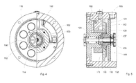
- Fig. 4 shows in a side view with partial section a dockable eddy current brake 100 for a rope length sensor.
- the eddy current brake 100 has a housing 102 in which a brake disk 104 is rotatably mounted with a shaft 106.
- the shaft 106 is fixedly connected by means of a coupling 105 to the shaft of a rope length sensor (see Fig. 5 ).
- the coupling 105 consists of flanges 107.
- the shaft of the rope length sensor can also be used by itself. This then projects, for example, out of the housing 102 of the rope length sensor and is guided into the housing 102 of the dockable eddy current brake 100.
- the shaft 106 is fixedly connected to the brake disk 104.
- the brake disk 104 consists of two components, a return plate 108 made of soft iron and an annular copper disk 110 (see Fig. 5 ).
- the brake disk 104 forms the rotor unit 109 of the eddy current brake 100.
- the rotor unit 109 is in Fig. 4 not shown and only in Fig. 5 visible, noticeable.
- a partial view of a stator unit 111 is shown.
- the stator unit 111 is formed by permanent magnets 112, 114 and a return plate 116 made of soft iron.
- the stator unit 111 is on a Holding plate 133 fixed.
- the permanent magnets 112, 114 are arranged annularly on the return plate 116.
- the permanent magnets 112, 114 are round-block magnets that are axially mounted on the return plate 116. In this case, the polarity of the permanent magnets 112 changes with the polarity of the permanent magnets 114.
- Fig. 5 shows a longitudinal section of the eddy current brake 100 according to the invention Fig. 4 ,
- the eddy current brake 100 is located in the housing 102.
- the shaft 106 is guided transversely through the housing 102 and rotatably supported therein.
- the clutch 105 With the clutch 105, the eddy current brake 100 can be docked to the rope length sensor.
- a rotation of the shaft of the cable length sensor is transmitted via the coupling 105 directly to the shaft 106, on which the brake disk 104 is firmly seated.
- the stator unit 111 is fixed inside the housing 102.
- the rotating brake disk 104 is largely perpendicular to the magnetic field lines of the permanent magnets 112, 114.
- the brake disk 104 consists of the annular return plate 108 made of soft iron and one of the annular copper disk 110.
- the permanent magnets 112 and 114 are seated on the return plate 116.
- Fig. 6 shows in a simplified schematic diagram a section of an eddy current brake 100, as for example. According to Fig. 4 respectively. Fig. 5 is shown.
- the brake disk 104 is mounted on the rotatably mounted shaft 106. This forms the rotor unit 109 of the eddy current brake 100.
- the brake disk 104 is arranged at a distance L from the annularly arranged permanent magnets 112, 114 of the stator unit 111.
- the annular return plate 116 can also be seen, on which the permanent magnets 112, 114 designed as round block magnets are fastened.
- the operation is as follows based on the Fig. 6 briefly explained:
- the braking torque is generated by the relative speed between the stator 111 standing and the moving rotor unit 109.
- the eddy current brake 100 operates contactless and thus wear-free.
- the electrically conductive brake disk 104 is moved in the magnetic field of the permanent magnets 112, 114. In this case, voltages are generated due to eddy currents. These in turn generate a magnetic field which counteracts the generating field.
- the moving brake disc 104 is thereby braked.
- the kinetic energy is thereby converted into heat.
- the strength of the braking effect is dependent in particular on the conductivity of the brake disk 104.
- the relative speed between the moving rotor unit 109 and the stator unit 111 also plays a role in addition to the distance L between the magnetic field of the permanent magnets 112, 114 and the brake disk. Furthermore, the direction of the magnetic field has an influence on the braking effect. The braking torque is almost linear to the rotational speed of the brake disk 104.
- the brake disc 36 rotates at the appropriate speed in the magnetic field of the statically arranged permanent magnets 28, 30.
- eddy currents are generated, which counteracting Generate magnetic field, which brakes the brake disc 26 together with the cable drum 16 controlled.
Landscapes
- Engineering & Computer Science (AREA)
- Mechanical Engineering (AREA)
- Automation & Control Theory (AREA)
- Dynamo-Electric Clutches, Dynamo-Electric Brakes (AREA)
- Measurement Of Length, Angles, Or The Like Using Electric Or Magnetic Means (AREA)
- Arrangements For Transmission Of Measured Signals (AREA)
- Transmission And Conversion Of Sensor Element Output (AREA)
Claims (5)
- Transmetteur de longueur de câble (10) comprenant(a) un bâti (14) et/ou un cadre,(b) un tambour de câble (16) logé de manière à tourner dans le bâti (14) et/ou le cadre et sur lequel est prévu un élément de mesure (18) de sorte à pouvoir être enroulé et déroulé,(c) un capteur de taux de rotation (50) qui saisit le nombre de tours du tambour de câble (16) et(d) un enrouleur automatique (20) pour le tambour de câble qui enroule l'élément de mesure déroulé sur le tambour de câble,(e) un frein à courant de Foucault (12) destiné à freiner le tambour de câble (16) en cas de défauts, notamment en cas de défaut fonctionnel et/ou de défaut de commande, le frein à courant de Foucault (12) présentant un élément fixe (32) et un élément tournant (52),(f) l'élément fixe (32) étant configuré sous forme de disque sur lequel sont disposés circulairement des aimants permanents (28, 30) polarisés en alternance ou
l'élément fixe (32) en forme de disque étant prévu avec des aimants annulaires multipolaires disposés en forme de secteur,(g) l'élément tournant (52) comprend un disque de frein (36) prévu sur le tambour de câble (16), le disque de frein (36) étant disposé perpendiculairement aux lignes de champ magnétique des aimants permanents (28, 30),
caractérise en ce que(h) le disque de frein (36) comprend un disque en cuivre et une planque métallique (38) en fer doux. - Transmetteur de longueur de câble (10) selon la revendication 1, caractérisé en ce que le frein à courant de Foucault (12) est intégré dans le bâti (14) et/ou le cadre du transmetteur de longueur de câble (10).
- Transmetteur de longueur de câble (10) selon l'une des revendications 1 à 4, caractérisé en ce que l'élément fixe (32) en forme de disque du frein à courant de Foucault (12) est relié à une bride de bâti et/ou de cadre.
- Transmetteur de longueur de câble (10) selon l'une des revendications précédentes, caractérisé en ce que le frein à courant de Foucault (12) est intégré dans le mécanisme de treuil.
- Transmetteur de longueur de câble (10) selon l'une des revendications 1 à 4, caractérisé en ce que l'écart (L) entre le disque de frein (36) et l'élément fixe (32) en forme de disque est prévu de sorte à pouvoir être réglé.
Applications Claiming Priority (1)
| Application Number | Priority Date | Filing Date | Title |
|---|---|---|---|
| DE201220101380 DE202012101380U1 (de) | 2012-04-16 | 2012-04-16 | Seillängengeber |
Publications (2)
| Publication Number | Publication Date |
|---|---|
| EP2653428A1 EP2653428A1 (fr) | 2013-10-23 |
| EP2653428B1 true EP2653428B1 (fr) | 2015-09-30 |
Family
ID=46547402
Family Applications (1)
| Application Number | Title | Priority Date | Filing Date |
|---|---|---|---|
| EP13162691.3A Revoked EP2653428B1 (fr) | 2012-04-16 | 2013-04-08 | Capteur de longueur de câble |
Country Status (3)
| Country | Link |
|---|---|
| EP (1) | EP2653428B1 (fr) |
| DE (1) | DE202012101380U1 (fr) |
| ES (1) | ES2557738T3 (fr) |
Cited By (2)
| Publication number | Priority date | Publication date | Assignee | Title |
|---|---|---|---|---|
| EP3296248A1 (fr) * | 2016-09-19 | 2018-03-21 | SHM Solutions AS | Système de freinage pour un treuil |
| EP3997414A4 (fr) * | 2019-07-12 | 2023-07-26 | Milwaukee Electric Tool Corporation | Mètre à ruban avec dispositif de commande de vitesse de rétraction magnétique |
Families Citing this family (8)
| Publication number | Priority date | Publication date | Assignee | Title |
|---|---|---|---|---|
| CN103673956B (zh) * | 2013-12-13 | 2016-03-30 | 中联重科股份有限公司 | 卷扬的放绳长度检测系统、方法、装置及起重机 |
| WO2016172509A1 (fr) * | 2015-04-24 | 2016-10-27 | Conductix, Inc. | Frein à courant de foucault d'enrouleur de câble |
| CN110446904B (zh) * | 2017-03-24 | 2022-03-08 | 米沃奇电动工具公司 | 具有基于流体的收回速度控制器的卷尺 |
| DE102017109355B3 (de) * | 2017-05-02 | 2018-07-05 | Flexi-Bogdahn Technik Gmbh & Co. Kg | Rollleine zum Aufrollen und Abrollen einer Leine |
| CN111725739B (zh) * | 2020-05-23 | 2021-10-15 | 国网河北省电力有限公司邯郸供电分公司 | 一种新型的配网工程施工保证弧垂一致的架空放线工具 |
| DE102020130471A1 (de) | 2020-11-18 | 2022-05-19 | Tridelta Magnetsysteme Gmbh | Magnetscheibe, Wirbelstrombremse, Seiltrommel mit Wirbelstrombremse und Verwendung einer derartigen Seiltrommel zur Absicherung eines Industriekletterers |
| FI129445B (en) * | 2021-02-11 | 2022-02-28 | Valmet Technologies Oy | Braking of an unpowered roller in a fiber web machine, especially in a roller cutting machine |
| DE102021128974B3 (de) | 2021-11-08 | 2023-03-23 | Fernsteuergeräte Kurt Oelsch GmbH | Seillängengeber mit elektrischem Antrieb |
Citations (6)
| Publication number | Priority date | Publication date | Assignee | Title |
|---|---|---|---|---|
| GB1311044A (en) | 1970-01-08 | 1973-03-21 | Ciba Geigy Ag | 2-hydroxypropylamine derivatives their preparation and pharma ceutical preparations comprising them |
| DE3403144A1 (de) | 1984-01-31 | 1985-08-14 | Palitex Project-Company Gmbh, 4150 Krefeld | Anordnung zur veraenderung der zugkraft eines laufenden fadens |
| EP0440246A1 (fr) | 1990-02-02 | 1991-08-07 | Barmag Ag | Dispositif du frein pour fils ou torons métalliques |
| EP0994327A2 (fr) | 1998-08-27 | 2000-04-19 | Celesco Transducer Products, Inc. | Dispositif de retenue pour transducteurs linéaires |
| EP1014031A2 (fr) | 1998-12-22 | 2000-06-28 | Asm Automation, Sensorik, Messtechnik Gmbh | Capteur de distance avec entraínement longitudinal pour le tambour de câble de mesure |
| EP1014032A2 (fr) | 1998-12-22 | 2000-06-28 | Asm Automation, Sensorik, Messtechnik Gmbh | Capteur de déplacement à cable |
Family Cites Families (8)
| Publication number | Priority date | Publication date | Assignee | Title |
|---|---|---|---|---|
| DE3019190C2 (de) * | 1980-05-20 | 1982-12-23 | Bergwerksverband Gmbh, 4300 Essen | Vorrichtung zur kontinuierlichen Messung der Abstandsänderungen zwischen Meßpunkten an Gebirgsformationen |
| DE8801109U1 (fr) | 1988-01-29 | 1988-06-01 | Oelsch Kg, 1000 Berlin, De | |
| JPH0711098Y2 (ja) * | 1989-05-26 | 1995-03-15 | 昭和飛行機工業株式会社 | クレーン車用のウインチ装置 |
| DE29707252U1 (de) | 1997-04-15 | 1997-07-17 | Flock Romanus | Kondomverpackung zum einhändigen Öffnen |
| DE19839027C1 (de) * | 1998-08-27 | 2000-02-10 | Asm Automation Sensorik Messte | Meßseil-Wegsensor |
| DE19925364C3 (de) | 1999-06-02 | 2003-04-10 | Oelsch Fernsteuergeraete | Seillängengeber zur Erzeugung eines Seillängensignals |
| DE602005002743T2 (de) | 2004-04-29 | 2008-01-24 | Terex-Demag Gmbh & Co. Kg | Seilwickelsystem zum Auf- und Abwickeln von Stahlseilen von Kranen |
| DE202004007424U1 (de) | 2004-05-06 | 2004-07-22 | Fernsteuergeräte Kurt Oelsch GmbH | Seillängengeber |
-
2012
- 2012-04-16 DE DE201220101380 patent/DE202012101380U1/de not_active Expired - Lifetime
-
2013
- 2013-04-08 EP EP13162691.3A patent/EP2653428B1/fr not_active Revoked
- 2013-04-08 ES ES13162691.3T patent/ES2557738T3/es active Active
Patent Citations (6)
| Publication number | Priority date | Publication date | Assignee | Title |
|---|---|---|---|---|
| GB1311044A (en) | 1970-01-08 | 1973-03-21 | Ciba Geigy Ag | 2-hydroxypropylamine derivatives their preparation and pharma ceutical preparations comprising them |
| DE3403144A1 (de) | 1984-01-31 | 1985-08-14 | Palitex Project-Company Gmbh, 4150 Krefeld | Anordnung zur veraenderung der zugkraft eines laufenden fadens |
| EP0440246A1 (fr) | 1990-02-02 | 1991-08-07 | Barmag Ag | Dispositif du frein pour fils ou torons métalliques |
| EP0994327A2 (fr) | 1998-08-27 | 2000-04-19 | Celesco Transducer Products, Inc. | Dispositif de retenue pour transducteurs linéaires |
| EP1014031A2 (fr) | 1998-12-22 | 2000-06-28 | Asm Automation, Sensorik, Messtechnik Gmbh | Capteur de distance avec entraínement longitudinal pour le tambour de câble de mesure |
| EP1014032A2 (fr) | 1998-12-22 | 2000-06-28 | Asm Automation, Sensorik, Messtechnik Gmbh | Capteur de déplacement à cable |
Non-Patent Citations (3)
| Title |
|---|
| "MAGNETKUPPLUNGEN", PRODUKTKATALOG DER FIRMA TRIDELTA MAGNETSYSTEME GMBH, October 2011 (2011-10-01), pages 44, XP055468958 |
| "TECHNISCHE INFORMATIONEN", TECHNISCHE INFORMATION DER FIRMA MAGNETFABRIK SCHRAMBERG, 2004, pages 68 - 69, XP055468960 |
| DIETMAR SCHWEGLER: "Permanentmagnete", vol. 387, 2016, ISBN: 9783862361007, article "Die Bibliothek der Technik ANWENDUNGEN", pages: 52 - 55, XP055468966 |
Cited By (2)
| Publication number | Priority date | Publication date | Assignee | Title |
|---|---|---|---|---|
| EP3296248A1 (fr) * | 2016-09-19 | 2018-03-21 | SHM Solutions AS | Système de freinage pour un treuil |
| EP3997414A4 (fr) * | 2019-07-12 | 2023-07-26 | Milwaukee Electric Tool Corporation | Mètre à ruban avec dispositif de commande de vitesse de rétraction magnétique |
Also Published As
| Publication number | Publication date |
|---|---|
| DE202012101380U1 (de) | 2012-06-15 |
| ES2557738T3 (es) | 2016-01-28 |
| EP2653428A1 (fr) | 2013-10-23 |
Similar Documents
| Publication | Publication Date | Title |
|---|---|---|
| EP2653428B1 (fr) | Capteur de longueur de câble | |
| EP1014031B1 (fr) | Capteur de distance avec entraînement longitudinal pour le tambour de câble de mesure | |
| WO2019138015A1 (fr) | Dispositif de freinage magnétorhéologique et procédé | |
| EP1995203B1 (fr) | Unité de surveillance de la vitesse et de l'accélération dotée d'un déclenchement assisté électroniquement destiné à l'utilisation pour organe convoyeur | |
| CN102652029A (zh) | 带有制动机构的脱落保护安全装置 | |
| DE102008008835A1 (de) | Vorrichtung zum Ermitteln eines Drehmoments | |
| EP1678020B1 (fr) | Frein a disque | |
| EP1478900A2 (fr) | Mecanisme de transmission et codeur de rotation equipe dudit mecanisme | |
| DE102009032808B4 (de) | Vorrichtung zum Messen einer Umwucht eines Fahrzeugrades | |
| EP0778239A1 (fr) | Capteur de longueur de corde avec un tambour mobile longitudinalement | |
| WO2020104428A1 (fr) | Limiteur de vitesse pour un engin de levage comprenant un frein actionné par la force centrifuge | |
| EP4078330A1 (fr) | Composant d'appareil pourvu d'un dispositif de freinage magnétorhéologique | |
| DE102011106635A1 (de) | Seildurchlaufwinde | |
| EP3299192A1 (fr) | Dispositif de frein additionnel pour une remorque de véhicule pourvue d'un système de freinage par inertie | |
| DE102007007234A1 (de) | Elektromechanische Stellvorrichtung für Radaufhängungen von Kraftfahrzeugen | |
| EP1014032B1 (fr) | Capteur de déplacement à cable | |
| EP2363570A2 (fr) | Dispositif de moteur tubulaire pour un dispositif d'obscurcissement | |
| DE10245995A1 (de) | Schubmast-Gabelstapler | |
| EP2962980B1 (fr) | Treuil de remorquage pour un appareil de sport aérien et procédé de fonctionnement d'un tel treuil de remorquage | |
| DE19814787A1 (de) | Elektromechanische Radbremsvorrichtung | |
| EP3180535B1 (fr) | Système de freinage | |
| DE102021128974B3 (de) | Seillängengeber mit elektrischem Antrieb | |
| DE10224418B4 (de) | Seiltrommel mit Sensorik zur Begrenzung des Abwickelns des Hubseils | |
| DE102018219979A1 (de) | Elektromotorische Antriebeinrichtung, Bremsaktuator | |
| DE202010013006U1 (de) | Aufwicklung für Seillängengeber |
Legal Events
| Date | Code | Title | Description |
|---|---|---|---|
| PUAI | Public reference made under article 153(3) epc to a published international application that has entered the european phase |
Free format text: ORIGINAL CODE: 0009012 |
|
| AK | Designated contracting states |
Kind code of ref document: A1 Designated state(s): AL AT BE BG CH CY CZ DE DK EE ES FI FR GB GR HR HU IE IS IT LI LT LU LV MC MK MT NL NO PL PT RO RS SE SI SK SM TR |
|
| AX | Request for extension of the european patent |
Extension state: BA ME |
|
| 17P | Request for examination filed |
Effective date: 20140416 |
|
| RBV | Designated contracting states (corrected) |
Designated state(s): AL AT BE BG CH CY CZ DE DK EE ES FI FR GB GR HR HU IE IS IT LI LT LU LV MC MK MT NL NO PL PT RO RS SE SI SK SM TR |
|
| GRAP | Despatch of communication of intention to grant a patent |
Free format text: ORIGINAL CODE: EPIDOSNIGR1 |
|
| RIC1 | Information provided on ipc code assigned before grant |
Ipc: G01B 3/10 20060101ALN20150421BHEP Ipc: B65H 61/00 20060101ALN20150421BHEP Ipc: B65H 75/48 20060101ALN20150421BHEP Ipc: B66D 5/14 20060101AFI20150421BHEP Ipc: B66C 13/46 20060101ALI20150421BHEP Ipc: B66D 5/30 20060101ALI20150421BHEP Ipc: B65H 75/44 20060101ALN20150421BHEP |
|
| RIC1 | Information provided on ipc code assigned before grant |
Ipc: G01B 3/10 20060101ALN20150424BHEP Ipc: B66C 13/46 20060101ALI20150424BHEP Ipc: B66D 5/14 20060101AFI20150424BHEP Ipc: B65H 75/44 20060101ALN20150424BHEP Ipc: B65H 75/48 20060101ALN20150424BHEP Ipc: B66D 5/30 20060101ALI20150424BHEP Ipc: B65H 61/00 20060101ALN20150424BHEP |
|
| INTG | Intention to grant announced |
Effective date: 20150521 |
|
| GRAS | Grant fee paid |
Free format text: ORIGINAL CODE: EPIDOSNIGR3 |
|
| GRAA | (expected) grant |
Free format text: ORIGINAL CODE: 0009210 |
|
| AK | Designated contracting states |
Kind code of ref document: B1 Designated state(s): AL AT BE BG CH CY CZ DE DK EE ES FI FR GB GR HR HU IE IS IT LI LT LU LV MC MK MT NL NO PL PT RO RS SE SI SK SM TR |
|
| REG | Reference to a national code |
Ref country code: CH Ref legal event code: EP Ref country code: GB Ref legal event code: FG4D Free format text: NOT ENGLISH |
|
| REG | Reference to a national code |
Ref country code: AT Ref legal event code: REF Ref document number: 752278 Country of ref document: AT Kind code of ref document: T Effective date: 20151015 |
|
| REG | Reference to a national code |
Ref country code: IE Ref legal event code: FG4D Free format text: LANGUAGE OF EP DOCUMENT: GERMAN |
|
| REG | Reference to a national code |
Ref country code: DE Ref legal event code: R096 Ref document number: 502013001257 Country of ref document: DE |
|
| REG | Reference to a national code |
Ref country code: SE Ref legal event code: TRGR |
|
| REG | Reference to a national code |
Ref country code: ES Ref legal event code: FG2A Ref document number: 2557738 Country of ref document: ES Kind code of ref document: T3 Effective date: 20160128 |
|
| PG25 | Lapsed in a contracting state [announced via postgrant information from national office to epo] |
Ref country code: LV Free format text: LAPSE BECAUSE OF FAILURE TO SUBMIT A TRANSLATION OF THE DESCRIPTION OR TO PAY THE FEE WITHIN THE PRESCRIBED TIME-LIMIT Effective date: 20150930 Ref country code: GR Free format text: LAPSE BECAUSE OF FAILURE TO SUBMIT A TRANSLATION OF THE DESCRIPTION OR TO PAY THE FEE WITHIN THE PRESCRIBED TIME-LIMIT Effective date: 20151231 Ref country code: LT Free format text: LAPSE BECAUSE OF FAILURE TO SUBMIT A TRANSLATION OF THE DESCRIPTION OR TO PAY THE FEE WITHIN THE PRESCRIBED TIME-LIMIT Effective date: 20150930 |
|
| REG | Reference to a national code |
Ref country code: LT Ref legal event code: MG4D |
|
| REG | Reference to a national code |
Ref country code: NL Ref legal event code: FP |
|
| PG25 | Lapsed in a contracting state [announced via postgrant information from national office to epo] |
Ref country code: HR Free format text: LAPSE BECAUSE OF FAILURE TO SUBMIT A TRANSLATION OF THE DESCRIPTION OR TO PAY THE FEE WITHIN THE PRESCRIBED TIME-LIMIT Effective date: 20150930 Ref country code: RS Free format text: LAPSE BECAUSE OF FAILURE TO SUBMIT A TRANSLATION OF THE DESCRIPTION OR TO PAY THE FEE WITHIN THE PRESCRIBED TIME-LIMIT Effective date: 20150930 |
|
| REG | Reference to a national code |
Ref country code: NO Ref legal event code: T2 Effective date: 20150930 |
|
| REG | Reference to a national code |
Ref country code: FR Ref legal event code: PLFP Year of fee payment: 4 |
|
| PG25 | Lapsed in a contracting state [announced via postgrant information from national office to epo] |
Ref country code: SK Free format text: LAPSE BECAUSE OF FAILURE TO SUBMIT A TRANSLATION OF THE DESCRIPTION OR TO PAY THE FEE WITHIN THE PRESCRIBED TIME-LIMIT Effective date: 20150930 Ref country code: CZ Free format text: LAPSE BECAUSE OF FAILURE TO SUBMIT A TRANSLATION OF THE DESCRIPTION OR TO PAY THE FEE WITHIN THE PRESCRIBED TIME-LIMIT Effective date: 20150930 Ref country code: IS Free format text: LAPSE BECAUSE OF FAILURE TO SUBMIT A TRANSLATION OF THE DESCRIPTION OR TO PAY THE FEE WITHIN THE PRESCRIBED TIME-LIMIT Effective date: 20160130 Ref country code: EE Free format text: LAPSE BECAUSE OF FAILURE TO SUBMIT A TRANSLATION OF THE DESCRIPTION OR TO PAY THE FEE WITHIN THE PRESCRIBED TIME-LIMIT Effective date: 20150930 |
|
| PG25 | Lapsed in a contracting state [announced via postgrant information from national office to epo] |
Ref country code: PL Free format text: LAPSE BECAUSE OF FAILURE TO SUBMIT A TRANSLATION OF THE DESCRIPTION OR TO PAY THE FEE WITHIN THE PRESCRIBED TIME-LIMIT Effective date: 20150930 Ref country code: RO Free format text: LAPSE BECAUSE OF FAILURE TO SUBMIT A TRANSLATION OF THE DESCRIPTION OR TO PAY THE FEE WITHIN THE PRESCRIBED TIME-LIMIT Effective date: 20150930 Ref country code: PT Free format text: LAPSE BECAUSE OF FAILURE TO SUBMIT A TRANSLATION OF THE DESCRIPTION OR TO PAY THE FEE WITHIN THE PRESCRIBED TIME-LIMIT Effective date: 20160201 |
|
| REG | Reference to a national code |
Ref country code: DE Ref legal event code: R026 Ref document number: 502013001257 Country of ref document: DE |
|
| PLBI | Opposition filed |
Free format text: ORIGINAL CODE: 0009260 |
|
| 26 | Opposition filed |
Opponent name: ASM AUTOMATION SENSORIK MESSTECHNIK GMBH Effective date: 20160628 |
|
| PLAX | Notice of opposition and request to file observation + time limit sent |
Free format text: ORIGINAL CODE: EPIDOSNOBS2 |
|
| PG25 | Lapsed in a contracting state [announced via postgrant information from national office to epo] |
Ref country code: DK Free format text: LAPSE BECAUSE OF FAILURE TO SUBMIT A TRANSLATION OF THE DESCRIPTION OR TO PAY THE FEE WITHIN THE PRESCRIBED TIME-LIMIT Effective date: 20150930 Ref country code: BE Free format text: LAPSE BECAUSE OF NON-PAYMENT OF DUE FEES Effective date: 20160430 |
|
| PG25 | Lapsed in a contracting state [announced via postgrant information from national office to epo] |
Ref country code: SI Free format text: LAPSE BECAUSE OF FAILURE TO SUBMIT A TRANSLATION OF THE DESCRIPTION OR TO PAY THE FEE WITHIN THE PRESCRIBED TIME-LIMIT Effective date: 20150930 |
|
| PLBB | Reply of patent proprietor to notice(s) of opposition received |
Free format text: ORIGINAL CODE: EPIDOSNOBS3 |
|
| PG25 | Lapsed in a contracting state [announced via postgrant information from national office to epo] |
Ref country code: LU Free format text: LAPSE BECAUSE OF FAILURE TO SUBMIT A TRANSLATION OF THE DESCRIPTION OR TO PAY THE FEE WITHIN THE PRESCRIBED TIME-LIMIT Effective date: 20160408 |
|
| REG | Reference to a national code |
Ref country code: IE Ref legal event code: MM4A |
|
| REG | Reference to a national code |
Ref country code: FR Ref legal event code: PLFP Year of fee payment: 5 |
|
| PG25 | Lapsed in a contracting state [announced via postgrant information from national office to epo] |
Ref country code: IE Free format text: LAPSE BECAUSE OF NON-PAYMENT OF DUE FEES Effective date: 20160408 |
|
| GBPC | Gb: european patent ceased through non-payment of renewal fee |
Effective date: 20170408 |
|
| PG25 | Lapsed in a contracting state [announced via postgrant information from national office to epo] |
Ref country code: GB Free format text: LAPSE BECAUSE OF NON-PAYMENT OF DUE FEES Effective date: 20170408 |
|
| REG | Reference to a national code |
Ref country code: DE Ref legal event code: R064 Ref document number: 502013001257 Country of ref document: DE Ref country code: DE Ref legal event code: R103 Ref document number: 502013001257 Country of ref document: DE |
|
| REG | Reference to a national code |
Ref country code: FR Ref legal event code: PLFP Year of fee payment: 6 |
|
| PG25 | Lapsed in a contracting state [announced via postgrant information from national office to epo] |
Ref country code: SM Free format text: LAPSE BECAUSE OF FAILURE TO SUBMIT A TRANSLATION OF THE DESCRIPTION OR TO PAY THE FEE WITHIN THE PRESCRIBED TIME-LIMIT Effective date: 20150930 Ref country code: CY Free format text: LAPSE BECAUSE OF FAILURE TO SUBMIT A TRANSLATION OF THE DESCRIPTION OR TO PAY THE FEE WITHIN THE PRESCRIBED TIME-LIMIT Effective date: 20150930 Ref country code: HU Free format text: LAPSE BECAUSE OF FAILURE TO SUBMIT A TRANSLATION OF THE DESCRIPTION OR TO PAY THE FEE WITHIN THE PRESCRIBED TIME-LIMIT; INVALID AB INITIO Effective date: 20130408 |
|
| PG25 | Lapsed in a contracting state [announced via postgrant information from national office to epo] |
Ref country code: MK Free format text: LAPSE BECAUSE OF FAILURE TO SUBMIT A TRANSLATION OF THE DESCRIPTION OR TO PAY THE FEE WITHIN THE PRESCRIBED TIME-LIMIT Effective date: 20150930 Ref country code: MT Free format text: LAPSE BECAUSE OF FAILURE TO SUBMIT A TRANSLATION OF THE DESCRIPTION OR TO PAY THE FEE WITHIN THE PRESCRIBED TIME-LIMIT Effective date: 20150930 Ref country code: TR Free format text: LAPSE BECAUSE OF FAILURE TO SUBMIT A TRANSLATION OF THE DESCRIPTION OR TO PAY THE FEE WITHIN THE PRESCRIBED TIME-LIMIT Effective date: 20150930 Ref country code: MC Free format text: LAPSE BECAUSE OF FAILURE TO SUBMIT A TRANSLATION OF THE DESCRIPTION OR TO PAY THE FEE WITHIN THE PRESCRIBED TIME-LIMIT Effective date: 20150930 |
|
| PGFP | Annual fee paid to national office [announced via postgrant information from national office to epo] |
Ref country code: NL Payment date: 20180423 Year of fee payment: 6 |
|
| RDAF | Communication despatched that patent is revoked |
Free format text: ORIGINAL CODE: EPIDOSNREV1 |
|
| STAA | Information on the status of an ep patent application or granted ep patent |
Free format text: STATUS: THE PATENT HAS BEEN GRANTED |
|
| PG25 | Lapsed in a contracting state [announced via postgrant information from national office to epo] |
Ref country code: BG Free format text: LAPSE BECAUSE OF FAILURE TO SUBMIT A TRANSLATION OF THE DESCRIPTION OR TO PAY THE FEE WITHIN THE PRESCRIBED TIME-LIMIT Effective date: 20150930 |
|
| PGFP | Annual fee paid to national office [announced via postgrant information from national office to epo] |
Ref country code: CH Payment date: 20180424 Year of fee payment: 6 Ref country code: NO Payment date: 20180420 Year of fee payment: 6 Ref country code: DE Payment date: 20180620 Year of fee payment: 6 Ref country code: FI Payment date: 20180418 Year of fee payment: 6 Ref country code: ES Payment date: 20180523 Year of fee payment: 6 |
|
| PGFP | Annual fee paid to national office [announced via postgrant information from national office to epo] |
Ref country code: FR Payment date: 20180424 Year of fee payment: 6 Ref country code: IT Payment date: 20180420 Year of fee payment: 6 Ref country code: AT Payment date: 20180418 Year of fee payment: 6 |
|
| PGFP | Annual fee paid to national office [announced via postgrant information from national office to epo] |
Ref country code: SE Payment date: 20180424 Year of fee payment: 6 |
|
| RDAG | Patent revoked |
Free format text: ORIGINAL CODE: 0009271 |
|
| STAA | Information on the status of an ep patent application or granted ep patent |
Free format text: STATUS: PATENT REVOKED |
|
| PG25 | Lapsed in a contracting state [announced via postgrant information from national office to epo] |
Ref country code: AL Free format text: LAPSE BECAUSE OF FAILURE TO SUBMIT A TRANSLATION OF THE DESCRIPTION OR TO PAY THE FEE WITHIN THE PRESCRIBED TIME-LIMIT Effective date: 20150930 |
|
| REG | Reference to a national code |
Ref country code: CH Ref legal event code: PL |
|
| 27W | Patent revoked |
Effective date: 20180420 |
|
| REG | Reference to a national code |
Ref country code: BE Ref legal event code: MM Effective date: 20160430 |
|
| REG | Reference to a national code |
Ref country code: AT Ref legal event code: MA03 Ref document number: 752278 Country of ref document: AT Kind code of ref document: T Effective date: 20180420 |
|
| REG | Reference to a national code |
Ref country code: SE Ref legal event code: ECNC |