EP0983852B1 - Ink film thickness control method and apparatus for multi-color printing press - Google Patents
Ink film thickness control method and apparatus for multi-color printing press Download PDFInfo
- Publication number
- EP0983852B1 EP0983852B1 EP99250296A EP99250296A EP0983852B1 EP 0983852 B1 EP0983852 B1 EP 0983852B1 EP 99250296 A EP99250296 A EP 99250296A EP 99250296 A EP99250296 A EP 99250296A EP 0983852 B1 EP0983852 B1 EP 0983852B1
- Authority
- EP
- European Patent Office
- Prior art keywords
- printing
- ink
- plate
- unit
- film thickness
- Prior art date
- Legal status (The legal status is an assumption and is not a legal conclusion. Google has not performed a legal analysis and makes no representation as to the accuracy of the status listed.)
- Expired - Lifetime
Links
Images


Classifications
-
- B—PERFORMING OPERATIONS; TRANSPORTING
- B41—PRINTING; LINING MACHINES; TYPEWRITERS; STAMPS
- B41F—PRINTING MACHINES OR PRESSES
- B41F31/00—Inking arrangements or devices
-
- B—PERFORMING OPERATIONS; TRANSPORTING
- B41—PRINTING; LINING MACHINES; TYPEWRITERS; STAMPS
- B41P—INDEXING SCHEME RELATING TO PRINTING, LINING MACHINES, TYPEWRITERS, AND TO STAMPS
- B41P2233/00—Arrangements for the operation of printing presses
- B41P2233/10—Starting-up the machine
- B41P2233/11—Pre-inking
Definitions
- the present invention relates to an ink film thickness control method and apparatus used in exchanging a printing plate in a multi-color printing press having a plurality of printing units each of which supplies ink in an ink fountain to a printing plate through an ink roller group and print the ink supplied to the printing plate on printing paper.
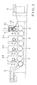
- Fig. 8 shows the main part of an ink supply apparatus in each printing unit (printing section) of a multi-color printing press.
- reference numeral 1 denotes an ink fountain; 2, ink stored in the ink fountain 1; 3, an ink fountain roller; 4, a plurality of ink fountain keys juxtaposed along the axial direction of the ink fountain roller 3; 5, an ink ductor roller; 6, an ink roller group; 6A, ink form rollers in the ink roller group 6; 7, a printing plate; and 8, a plate cylinder.
- the ink 2 in the ink fountain 1 is supplied by adjusting the aperture ratios of the ink fountain keys 4.
- the ink supplied to the ink fountain roller 3 is supplied to the printing plate 7 via the ink roller group 6 by the feed operation of the ink ductor roller 5. Printing paper fed from a paper feed section is printed with the ink supplied to the printing plate 7.
- the aperture ratio of each ink fountain key 4 and the rotation ratio of the ink fountain roller 3 are preset to values corresponding to the image of the printing plate 7. More specifically, the aperture ratio of each ink fountain key 4 and the rotation ratio of the ink fountain roller 3 are set to values corresponding to the image of the printing plate 7, and the ink 2 in the ink fountain 1 is supplied to the new printing plate 7 via the ink roller group 6. In this case, test printing is performed before final printing to adjust the ink supply amount, thereby obtaining a satisfactory color tone. With this operation, a desired ink film thickness distribution (gradient of thickness of the ink film) is formed on the ink roller group 6.
- the ink film thickness distribution for the previous printing plate remains on the ink roller group 6.
- the ink film thickness distribution for the previous printing plate must be gradually changed to the ink film thickness distribution for the printing plate 7. This operation excessively requires adjustment of the ink supply amount and test printing until a satisfactory color tone is obtained, resulting in problems including an increase in preparation time for printing, an increase in work load, waste of printing materials, a decrease in production efficiency, and an increase in cost.
- a printing unit is selected on a display (not shown).
- the "ink removing" mode (function) is selected, and the feed operation of the ink ductor roller 5 is stopped.
- the printing press is operated while keeping the printing plate mounted, thereby printing a predetermined number of paper sheets.
- a minimum ink film thickness distribution Ma (Fig. 7A; to be referred to as a first ink film thickness distribution hereinafter) necessary for printing is left on the ink roller group 6 such that the ink film thickness decreases from the upstream to the downstream. More specifically, an ink film thickness distribution corresponding to the image of the printing plate is removed from the ink film thickness distribution formed on the ink roller group 6, and the first ink film thickness distribution Ma corresponding to the no-image portion of the printing plate is left.
- the "pre-inking II” function is selected on the display to perform the "pre-inking II” operation.
- the aperture ratios of the ink fountain keys 4 and the rotation ratio of the ink fountain roller 3 are preset to values corresponding to the image of the printing plate 7.
- the printing press is operated.
- the ink ductor roller 5 is caused to perform the feed operation a predetermined number of times to superpose an ink film thickness distribution Mb (Fig. 7B; to be referred to as a second ink film thickness distribution hereinafter) corresponding to the image of the new printing plate 7 on the first ink film thickness distribution Ma left on the ink roller group 6.
- the second ink film thickness distribution Mb is superposed on the first ink film thickness distribution Ma, a predetermined number of sheets are test-printed. The density of the test-printed matters is checked. If the color tone is satisfactory, ink film thickness control by "ink removing + pre-inking II" is ended, and the operation shifts to final printing. On the other hand, the color tone checked by density check is not satisfactory, the ink film thickness distribution is finely adjusted by "pre-inking (+)” or “pre-inking (-)", and test-printing is performed again.
- an ink film thickness control method for a multi-color printing press having a plurality of printing units for continuously performing designated color printing on a printing paper by means of ink supplied to a printing plate through an ink roller group, comprising the steps of when in at least two of the printing units as plate exchange printing units, exchanges to new printing plates are simultaneously performed, setting a respective number of printing papers to be printed for ink removing in each unit in which plate exchange is performed, turning off an ink feed operation in each of the plate exchange printing units, and performing printing for ink removing in each of the plate exchange printing units on the basis of their respective set number of printing papers while keeping the previous printing plate mounted to form a first ink film thickness distribution minimum and necessary for printing on the ink roller group of the plate exchange printing unit.
- Fig. 2 shows the schematic arrangement of a four-color rotary printing press (four-color printing press) according to the first embodiment of the present invention.
- reference numerals 11-1 to 11-4 denote printing units .
- Each of the printing units 11-1 to 11-4 has the ink supply apparatus shown in Fig. 8.
- Reference numeral 17 denotes a blanket cylinder; and 9, an impression cylinder.
- an operation desk 13 as shown in Fig. 3 is near a delivery section 12.
- the operation desk 13 has an operation panel 13-1 on its upper surface.
- the operation panel 13-1 has an operation section 13-2 and display section 13-3 on its upper surface.
- a printing setting unit 14 constructed by a personal computer is mounted on the upper surface of the operation desk 13.
- the operation desk 13 incorporates a control unit (to be described later).
- the control unit and printing setting unit 14 construct a test printing system.
- the operation panel 13-1 has a slot 13-4 for receiving a recording medium such as a magnetic card 15 shown in Fig. 4A or a floppy disk 16 shown in Fig. 4B.
- Final printing data (print data) prepared on the basis of the image area information of a printing plate is recorded on the recording medium. More specifically, set value data such as a printing unit which uses the printing plate, the aperture ratio of the ink fountain key of the printing unit, and the rotation ratio of the ink fountain roller are recorded as final printing data in units of corresponding printing plates.
- a "pre-inking I”, "ink removing”, “pre-inking II”, “pre-inking (+)”, “pre-inking (-)”, or "test printing” mode (function) is selected on the menu window.
- Fig. 5 shows the electrical arrangement of the printing press including the printing setting unit 14.
- reference numeral 21 denotes a CPU (Central Processing Unit) for performing various processing operations; 22, a ROM (Read Only Memory) storing various programs for executing the respective modes; 23, a RAM (Random Access Memory) for storing various data; 24 and 25, I/O interfaces; 26, a printing control unit for controlling printing by the printing press; 27, a feed control unit for ON/OFF-controlling the feed mechanism for feeding ink; 28, a rotation ratio control unit for controlling the rotation ratio of the fountain roller; 29, an aperture ratio control unit for controlling the aperture ratio of an ink key; and 30, a drive unit for driving a recording medium such as a floppy disk.
- a CPU Central Processing Unit
- ROM Read Only Memory
- RAM Random Access Memory
- the I/O interface 24 is connected to the operation section 13-2, display section 13-3, and printing setting unit 14.
- the I/O interface 25 is connected to the printing control unit 26, feed control unit 27, rotation ratio control unit 28, aperture ratio control unit 29, and drive unit 30.
- the printing control unit 26, feed control unit 27, rotation ratio control unit 28, and aperture ratio control unit 29 are prepared for each of the printing units 11-1 to 11-4.
- a card read unit is connected to the I/O interface 25 in place of the drive unit 30.
- the CPU 21 Upon receiving various input information, the CPU 21 accesses the RAM 23 to perform various processing operations in accordance with the programs stored in the ROM 22.
- the CPU 21 has an ink removing section 21a and pre-inking II section 21b as means for performing various processing operations. Pieces of input information to the CPU 21 are supplied to the display section 13-3, printing setting unit 14, printing control unit 26, feed control unit 27, rotation ratio control unit 28, aperture ratio control unit 29, and drive unit 30 through the I/O interfaces 24 and 25.
- the printing setting unit 14 selects one of the "pre-inking I", “ink removing”, “pre-inking II”, “pre-inking (+)”, “pre-inking (-)”, or "test printing” modes (functions) to form an optimum ink film thickness on each roller of the ink roller group 6.
- a second ink film thickness distribution Mb is further formed on the first ink film thickness distribution Ma.
- the first ink film thickness distribution Ma is formed by removing the second ink film thickness distribution Mb.
- the second ink film thickness distribution Mb is formed on the first ink film thickness distribution Ma which has already been formed.
- the second ink film thickness distribution Mb is increased and decreased.
- the operation panel 13-1 has the slot 13-4 for receiving a recording medium such as the magnetic card 15 shown in Fig. 4A or floppy disk 16 shown in Fig. 4B.
- a recording medium on which final printing data (print data) prepared on the basis of the image area information of a printing plate is recorded is set in the slot 13-4. More specifically, set value data such as a printing unit which uses the printing plate, the aperture ratio of the ink fountain key of the printing unit, and the rotation ratio of the ink fountain roller are recorded on the recording medium as final printing data.
- the recording medium may be set in the printing setting unit 14 such that the printing setting unit 14 can load the final printing data.
- a menu window appears on the display.
- the menu window displays "pre-inking I”, “ink removing”, “pre-inking II”, “pre-inking (+)”, “pre-inking (-)”, and “test printing” as selectable modes. Numbers “1” to “4" corresponding to the printing units 11-1 to 11-4, respectively, are also displayed.
- the removing count takes a predetermined theoretical value N (the value N changes depending on factors such as ink and blanket).
- N the value changes depending on factors such as ink and blanket.
- the removing count changes in units of printing units due to the difference in ink trapping.
- values N1, N2, N3, and N4 (N4 > N3 > N2 > N1) are set as removing counts for the printing units 11-1, 11-2, 11-3, and 11-4, respectively, in consideration of ink trapping.
- the removing counts N1, N2, N3, and N4 are stored in the RAM 23.
- the operator sets a recording medium such as the magnetic card 15 or floppy disk 16 having print data of the new printing plates 7-1 to 7-4 in the slot 13-4 of the operation panel 13-1, thereby inputting new print data.
- the input print data of the new printing plates 7-1 to 7-4 are transferred to the CPU 21 through the interface 24 and stored in the RAM 23.
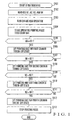
- the operator selects the numbers "1" to "4" corresponding to the printing units 11-1 to 11-4, respectively, in the menu window on the printing setting unit 14, and selects "ink removing". That is, the operator instructs the printing units 11-1 to 11-4 to start "ink removing" (step S101).
- the second ink film thickness distribution Mb corresponding to the image of the previous printing plate remains while being superposed on the first ink film thickness distribution Ma by the immediately preceding printing operation.
- the CPU 21 reads out the removing counts N1, N2, N3, and N4 from the RAM 23 (step S102).
- the CPU 21 and printing control unit 26 turn off the feed operation of ink ductor rollers 5 of the printing units 11-1 to 11-4. After this, the feed count is set to N4, and the printing press is operated while keeping the previous printing plates mounted (steps S103 and S104). In this case, the printing units 11-1 to 11-4 are in the throw-on state.
- the printing units 11-1 to 11-4 print printing papers conveyed from a feed section 10. In each of the printing units 11-1 to 11-4, printing is performed while keeping the feed operation of the ink ductor roller 5 stopped, so ink 2 in each of the printing units 11-1 to 11-4 is not supplied to the ink roller group 6.
- step S105 When a print count NA in the printing unit 11-1 reaches N1 (step S105), the CPU 21 issues a throw-off instruction to the printing unit 11-1 (step S106).
- the printing unit 11-1 is set in the throw-off state. Printing by the printing unit 11-1 is interrupted. After this, printing papers that have passed through the printing unit 11-1 without being printed are sent to the printing unit 11-2.
- the second ink film thickness distribution Mb is consumed by printing for the print count N1. Consequently, the history of ink in the ink roller group 6 is canceled, and the first ink film thickness distribution Ma (Fig. 7A) common to the previous and new printing plates is left in an appropriate amount.
- step S107 When a print count NB in the printing unit 11-2 reaches N2 (step S107), the CPU 21 issues a throw-off instruction to the printing unit 11-2 (step S108).
- the printing unit 11-2 is set in the throw-off state. Printing by the printing unit 11-2 is interrupted. After this, printing papers that have passed through the printing units 11-1 and 11-2 without being printed are sent to the printing unit 11-3.
- the ink held by the ink roller group 6 of the printing unit 11-2 only the second ink film thickness distribution Mb is consumed by printing for the print count N2. Consequently, the history of ink in the ink roller group 6 is canceled, and the first ink film thickness distribution Ma is left in an appropriate amount.
- step S109 When a print count NC in the printing unit 11-3 reaches N3 (step S109), the CPU 21 issues a throw-off instruction to the printing unit 11-3 (step S110).
- the printing unit 11-3 is set in the throw-off state. Printing by the printing unit 11-3 is interrupted. After this, printing papers that have passed through the printing units 11-1, 11-2, and 11-3 without being printed are sent to the printing unit 11-4.
- the ink held by the ink roller group 6 of the printing unit 11-3 only the second ink film thickness distribution Mb is consumed by printing for the print count N3. Consequently, the history of ink in the ink roller group 6 is canceled, and the first ink film thickness distribution Ma is left in an appropriate amount.
- step S111 When a print count ND in the printing unit 11-4 reaches N4 (step S111), the CPU 21 issues a throw-off instruction to the printing unit 11-4 (step S112).
- the printing unit 11-4 is set in the throw-off state. Printing by the printing unit 11-4 is interrupted. At this time, of the ink held by the ink roller group 6 of the printing unit 11-4, only the second ink film thickness distribution Mb is consumed by printing for the print count N4. Consequently, the history of ink in the ink roller group 6 is canceled, and the first ink film thickness distribution Ma is left in an appropriate amount. After this, the CPU 21 stops operating the printing press (step S113).
- throw-on means that the plate cylinder 8, blanket cylinder 17, and impression cylinder 9 shown in Fig. 2 are set in the throw-on state (contact state) to start printing.
- Throw-off means that the plate cylinder 8, blanket cylinder 17, and impression cylinder 9 shown in Fig. 2 are set in the throw-off state (separated state) to stop printing.
- Pre-inking II processing is executed by the pre-inking II section 21b of the CPU 21. This will be described below as processing of the CPU 21.
- the CPU 21 presets the aperture ratios of the ink fountain keys 4 and the rotation ratios of the ink fountain rollers 3 in the printing units 11-1 to 11-4 to values corresponding to the images of the new printing plates 7 and operates the printing press.
- the ink ductor roller 5 is caused to perform the feed operation a predetermined number of times to superpose the second ink film thickness distribution Mb on the first ink film thickness distribution Ma left on the ink roller group 6.
- the second ink film thickness distribution Mb for the next printing operation is accurately formed by "pre-inking II", and waste paper can be suppressed.
- the printing units 11-1 to 11-4 are simultaneously set in the throw-on state, and then, the throw-off timing is controlled in units of printing units 11-1 to 11-4.
- the printing units may be simultaneously set in the throw-off state after the throw-on timing is controlled in units of printing units.
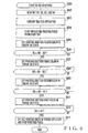
- the operator selects the numbers “1” to “4" corresponding to printing units 11-1 to 11-4, respectively, in the menu window on a printing setting unit 14, and selects "ink removing”. That is, the operator instructs the printing units 11-1 to 11-4 to start "ink removing" (step S601).
- a second ink film thickness distribution Mb corresponding to the image of the previous printing plate is superposed on a first ink film thickness distribution Ma.
- a CPU 21 reads out removing counts N1, N2, N3, and N4 from a RAM 23 (step S602).
- the CPU 21 turns off the feed operation of ink ductor rollers 5 of the printing units 11-1 to 11-4. After this, the feed count is set to N4, and the printing press is operated while keeping the previous printing plates mounted (steps S603 and S604). In this case, the printing units 11-1 to 11-4 are in the throw-off state.
- the CPU 21 issues a throw-on instruction to the printing unit 11-4 (step S605).
- the printing units 11-1 to 11-3 are set in the throw-off state, and the printing unit 11-4 is in the throw-on state.
- the printing unit 11-4 starts printing papers that have passed through the printing units 11-1 to 11-3 without being printed.
- step S606 When a pass count NC of printing papers in the printing unit 11-3 reaches N4 - N3 (step S606), the CPU 21 issues a throw-on instruction to the printing unit 11-3 (step S607).
- the printing unit 11-3 is set in the throw-on state and starts printing papers that have passed through the printing units 11-1 and 11-2 without being printed.
- step S608 When a pass count NB of printing papers in the printing unit 11-2 reaches N4 - N2 (step S608), the CPU 21 issues a throw-on instruction to the printing unit 11-2 (step S609).
- the printing unit 11-2 is set in the throw-on state and starts printing papers that have passed through the printing unit 11-1 without being printed.
- step S610 When a pass count NA of printing papers in the printing unit 11-1 reaches N4 - N1 (step S610), the CPU 21 issues a throw-on instruction to the printing unit 11-1 (step S611).
- the printing unit 11-1 is set in the throw-on state and starts printing papers sent from a feed section 10.
- step S612 When the print count NA in the printing unit 11-4 reaches "N4" (step S612), the CPU 21 issues a throw-off instruction to the printing units 11-1 to 11-4 and stops operating the printing press (step S613).
- the "(N4 - N1) + 1"th to "N4"th printing papers, i.e., N1 printing papers are printed while keeping the feed operation of the ink ductor roller 5 stopped.
- the history of ink in the ink roller group 6 is canceled, and the first ink film thickness distribution Ma is left in an appropriate amount.
- the "(N4 - N2) + 1"th to "N4"th printing papers, i.e., N2 printing papers are printed while keeping the feed operation of the ink ductor roller 5 stopped.
- the history of ink in the ink roller group 6 is canceled, and the first ink film thickness distribution Ma is left in an appropriate amount.
- the "(N4 - N3) + 1"th to "N4"th printing papers, i.e., N3 printing papers are printed while keeping the feed operation of the ink ductor roller 5 stopped.
- the history of ink in the ink roller group 6 is canceled, and the first ink film thickness distribution Ma is left in an appropriate amount.
- the "1"st to "N4"th printing papers i.e., N4 printing papers are printed while keeping the feed operation of the ink ductor roller 5 stopped.
- the history of ink in the ink roller group 6 is canceled, and the first ink film thickness distribution Ma is left in an appropriate amount.
- the throw-on or throw-off timing of each of the printing units 11-1 to 11-4 is controlled.
- throw-on or throw-off of an ink form roller 6A of each of the printing units 11-1 to 11-4 may be controlled at the same timing as the throw-on or throw-off timing shown in Fig. 1 or 6.
- the printing plates of the four-color printing units are simultaneously exchanged.
- the present invention can also be applied to a case wherein printing plates of two- or three-color printing units are exchanged.
- the number of printing papers to be used for ink removing is set in units of printing units which exchange the printing plates. Minimum ink necessary for printing can be left in an appropriate amount on the ink roller group of each printing unit which exchanges the printing plate. With this arrangement, an ink film thickness distribution for the next job can be accurately formed, and waste paper can be suppressed.
Landscapes
- Inking, Control Or Cleaning Of Printing Machines (AREA)
- Printing Methods (AREA)
Applications Claiming Priority (2)
| Application Number | Priority Date | Filing Date | Title |
|---|---|---|---|
| JP24844498 | 1998-09-02 | ||
| JP10248444A JP2000071424A (ja) | 1998-09-02 | 1998-09-02 | 多色印刷機におけるインキ膜厚制御方法 |
Publications (2)
| Publication Number | Publication Date |
|---|---|
| EP0983852A1 EP0983852A1 (en) | 2000-03-08 |
| EP0983852B1 true EP0983852B1 (en) | 2003-07-23 |
Family
ID=17178230
Family Applications (1)
| Application Number | Title | Priority Date | Filing Date |
|---|---|---|---|
| EP99250296A Expired - Lifetime EP0983852B1 (en) | 1998-09-02 | 1999-08-28 | Ink film thickness control method and apparatus for multi-color printing press |
Country Status (6)
| Country | Link |
|---|---|
| US (1) | US6367385B2 (enExample) |
| EP (1) | EP0983852B1 (enExample) |
| JP (1) | JP2000071424A (enExample) |
| AT (1) | ATE245536T1 (enExample) |
| DE (1) | DE69909690T2 (enExample) |
| ES (1) | ES2204064T3 (enExample) |
Cited By (4)
| Publication number | Priority date | Publication date | Assignee | Title |
|---|---|---|---|---|
| DE102006012597A1 (de) * | 2006-03-18 | 2007-09-20 | Man Roland Druckmaschinen Ag | Verfahren zur Reinigung von Druckplatten |
| DE102008029998A1 (de) | 2007-07-11 | 2009-01-15 | Manroland Ag | Abfördern von Druckfarbe |
| CN101389479B (zh) * | 2005-12-27 | 2012-08-08 | 曼罗兰公司 | 印刷机的输墨机构以及运行该输墨机构的方法 |
| DE102013014370A1 (de) | 2012-09-28 | 2014-04-03 | Heidelberger Druckmaschinen Ag | Verfahren zur Reinigung eines Druckwerks beim Auftragswechsel |
Families Citing this family (15)
| Publication number | Priority date | Publication date | Assignee | Title |
|---|---|---|---|---|
| JP4755327B2 (ja) | 2000-05-17 | 2011-08-24 | 株式会社小森コーポレーション | オフセット輪転機の切替作業の半自動化装置 |
| JP2001322252A (ja) | 2000-05-17 | 2001-11-20 | Komori Corp | オフセット輪転機の切替作業の自動化装置 |
| JP3556927B2 (ja) * | 2001-07-04 | 2004-08-25 | 三菱重工業株式会社 | 印刷機の運転支援装置及び印刷機の運転支援システム並びに印刷機の運転支援方法 |
| JP4128866B2 (ja) * | 2002-12-26 | 2008-07-30 | 株式会社小森コーポレーション | 印刷機のインキ供給量制御方法および装置 |
| JP4040968B2 (ja) * | 2002-12-26 | 2008-01-30 | 株式会社小森コーポレーション | 印刷機のインキ供給量制御方法および装置 |
| JP4064882B2 (ja) * | 2003-07-07 | 2008-03-19 | リョービ株式会社 | 印刷機のインキ量制御装置 |
| JP3976727B2 (ja) * | 2003-12-08 | 2007-09-19 | リョービ株式会社 | 印刷機のインキ練り方法及び印刷機 |
| DE102005040011C5 (de) † | 2005-08-23 | 2021-03-18 | manroland sheetfed GmbH | Verfahren zum Betreiben einer Druckmaschine |
| CN1939724B (zh) * | 2005-09-30 | 2010-05-12 | 深圳报业集团印务有限公司 | 报纸印刷的油墨预置方法 |
| US20070145618A1 (en) * | 2005-12-28 | 2007-06-28 | Kimberly-Clark Worldwide, Inc. | Methods of making microencapsulated delivery vehicles |
| DE102009000877C5 (de) * | 2009-02-16 | 2016-01-07 | Koenig & Bauer Ag | Verfahren zur Einstellung einer Flächendeckung und ein entsprechendes Verfahren zur Durchführung in einer mehrere Druckwerke aufweisenden Druckmaschine |
| JP6114503B2 (ja) * | 2012-04-26 | 2017-04-12 | 株式会社小森コーポレーション | インキ供給方法およびインキ供給装置 |
| US9623623B2 (en) | 2012-08-24 | 2017-04-18 | Hewlett-Packard Indigo B.V. | Thickness calibration of an embossing die |
| US9616657B2 (en) | 2013-10-01 | 2017-04-11 | Goss International Americas, Inc. | Closed loop ink thickness control system with reduced substrate waste in a printing press |
| DE102014007852A1 (de) * | 2014-05-22 | 2015-11-26 | Heidelberger Druckmaschinen Ag | Verfahren zum Betreiben einer Druckmaschine |
Family Cites Families (4)
| Publication number | Priority date | Publication date | Assignee | Title |
|---|---|---|---|---|
| DE3707695A1 (de) * | 1987-03-11 | 1988-09-22 | Heidelberger Druckmasch Ag | Verfahren zur definierten erzeugung einer dem fortdruck nahen farbverteilung im farbwerk von rotationsdruckmaschinen |
| US5174210A (en) * | 1990-04-27 | 1992-12-29 | Heidelberger Druckmaschinen Aktiengesellschaft | Preparation of the inking unit of a printing press for a change of printing job |
| DE4312229C2 (de) * | 1993-04-14 | 1999-10-28 | Heidelberger Druckmasch Ag | Verfahren zur definierten Erzeugung einer dem Fortdruck nahen Farbverteilung im Farbwerk von Rotationsdruckmaschinen |
| JPH1016193A (ja) * | 1996-06-27 | 1998-01-20 | Komori Corp | インキ膜厚の制御方法 |
-
1998
- 1998-09-02 JP JP10248444A patent/JP2000071424A/ja active Pending
-
1999
- 1999-08-28 EP EP99250296A patent/EP0983852B1/en not_active Expired - Lifetime
- 1999-08-28 AT AT99250296T patent/ATE245536T1/de not_active IP Right Cessation
- 1999-08-28 DE DE69909690T patent/DE69909690T2/de not_active Expired - Lifetime
- 1999-08-28 ES ES99250296T patent/ES2204064T3/es not_active Expired - Lifetime
- 1999-08-31 US US09/387,351 patent/US6367385B2/en not_active Expired - Lifetime
Cited By (4)
| Publication number | Priority date | Publication date | Assignee | Title |
|---|---|---|---|---|
| CN101389479B (zh) * | 2005-12-27 | 2012-08-08 | 曼罗兰公司 | 印刷机的输墨机构以及运行该输墨机构的方法 |
| DE102006012597A1 (de) * | 2006-03-18 | 2007-09-20 | Man Roland Druckmaschinen Ag | Verfahren zur Reinigung von Druckplatten |
| DE102008029998A1 (de) | 2007-07-11 | 2009-01-15 | Manroland Ag | Abfördern von Druckfarbe |
| DE102013014370A1 (de) | 2012-09-28 | 2014-04-03 | Heidelberger Druckmaschinen Ag | Verfahren zur Reinigung eines Druckwerks beim Auftragswechsel |
Also Published As
| Publication number | Publication date |
|---|---|
| DE69909690T2 (de) | 2004-04-15 |
| DE69909690D1 (de) | 2003-08-28 |
| JP2000071424A (ja) | 2000-03-07 |
| ES2204064T3 (es) | 2004-04-16 |
| US6367385B2 (en) | 2002-04-09 |
| US20010032558A1 (en) | 2001-10-25 |
| EP0983852A1 (en) | 2000-03-08 |
| ATE245536T1 (de) | 2003-08-15 |
Similar Documents
| Publication | Publication Date | Title |
|---|---|---|
| EP0983852B1 (en) | Ink film thickness control method and apparatus for multi-color printing press | |
| EP0816074B1 (en) | Ink film thickness control method for ink supply apparatus | |
| EP0897799B1 (en) | Automatic control of plate mounting, ink presetting and cylinder cleaning in a printing press | |
| RU2413616C2 (ru) | Печатная машина с модульной дополнительной печатной группой | |
| EP0925918B1 (en) | Method and apparatus for controlling ink film thickness | |
| US6474231B1 (en) | Multi-color printing press with common blanket cylinder | |
| JP3073609B2 (ja) | オフセット印刷機の定常印刷時のインキ分布を調整する方法 | |
| US7121208B2 (en) | Method of setting optimized pre-inking prior to the start of printing the current print job | |
| JPH11188844A (ja) | 印刷機におけるインキ膜厚の制御方法および制御装置 | |
| EP1155853B1 (en) | Printing press and printing press control method | |
| JP4368954B2 (ja) | 試刷りから本刷りへの切替方法および切替装置 | |
| JPH11188849A (ja) | インキ膜厚の制御方法および制御装置 | |
| US6615728B2 (en) | Printing press and printing press control method | |
| JP3917281B2 (ja) | インキ回収方法およびインキ回収装置 | |
| JPH11188848A (ja) | インキ膜厚の制御方法および制御装置 | |
| US6378431B1 (en) | Printing machine having a plurality of printing units for overprinting a plurality of inks in one pass | |
| JP2000037853A (ja) | 印刷機のインキ膜厚制御方法 | |
| JP4206532B2 (ja) | オフセット印刷機制御回路 | |
| JPH11188847A (ja) | インキ膜厚の制御方法および制御装置 | |
| EP1033248B1 (en) | Sheet supply control apparatus and method for printing press | |
| JP2008044381A (ja) | 多色印刷機におけるインキ膜厚制御方法 | |
| JP2001239651A (ja) | 印刷機の制御方法及び制御装置 | |
| JPH11207930A (ja) | インキ膜厚の制御方法およびインキ供給装置 | |
| JPH11188845A (ja) | インキ膜厚の制御方法および制御装置 | |
| JPH0655725A (ja) | 印刷機 |
Legal Events
| Date | Code | Title | Description |
|---|---|---|---|
| PUAI | Public reference made under article 153(3) epc to a published international application that has entered the european phase |
Free format text: ORIGINAL CODE: 0009012 |
|
| AK | Designated contracting states |
Kind code of ref document: A1 Designated state(s): AT BE CH CY DE DK ES FI FR GB GR IE IT LI LU MC NL PT SE |
|
| AX | Request for extension of the european patent |
Free format text: AL;LT;LV;MK;RO;SI |
|
| 17P | Request for examination filed |
Effective date: 20000321 |
|
| AKX | Designation fees paid |
Free format text: AT BE CH CY DE DK ES FI FR GB GR IE IT LI LU MC NL PT SE |
|
| 17Q | First examination report despatched |
Effective date: 20020703 |
|
| GRAH | Despatch of communication of intention to grant a patent |
Free format text: ORIGINAL CODE: EPIDOS IGRA |
|
| GRAH | Despatch of communication of intention to grant a patent |
Free format text: ORIGINAL CODE: EPIDOS IGRA |
|
| GRAA | (expected) grant |
Free format text: ORIGINAL CODE: 0009210 |
|
| AK | Designated contracting states |
Designated state(s): AT BE CH CY DE DK ES FI FR GB GR IE IT LI LU MC NL PT SE |
|
| PG25 | Lapsed in a contracting state [announced via postgrant information from national office to epo] |
Ref country code: FI Free format text: LAPSE BECAUSE OF FAILURE TO SUBMIT A TRANSLATION OF THE DESCRIPTION OR TO PAY THE FEE WITHIN THE PRESCRIBED TIME-LIMIT Effective date: 20030723 Ref country code: BE Free format text: LAPSE BECAUSE OF FAILURE TO SUBMIT A TRANSLATION OF THE DESCRIPTION OR TO PAY THE FEE WITHIN THE PRESCRIBED TIME-LIMIT Effective date: 20030723 Ref country code: AT Free format text: LAPSE BECAUSE OF FAILURE TO SUBMIT A TRANSLATION OF THE DESCRIPTION OR TO PAY THE FEE WITHIN THE PRESCRIBED TIME-LIMIT Effective date: 20030723 |
|
| REG | Reference to a national code |
Ref country code: GB Ref legal event code: FG4D |
|
| REG | Reference to a national code |
Ref country code: CH Ref legal event code: EP |
|
| REG | Reference to a national code |
Ref country code: IE Ref legal event code: FG4D |
|
| PG25 | Lapsed in a contracting state [announced via postgrant information from national office to epo] |
Ref country code: LU Free format text: LAPSE BECAUSE OF NON-PAYMENT OF DUE FEES Effective date: 20030828 Ref country code: IE Free format text: LAPSE BECAUSE OF NON-PAYMENT OF DUE FEES Effective date: 20030828 Ref country code: CY Free format text: LAPSE BECAUSE OF FAILURE TO SUBMIT A TRANSLATION OF THE DESCRIPTION OR TO PAY THE FEE WITHIN THE PRESCRIBED TIME-LIMIT Effective date: 20030828 |
|
| REF | Corresponds to: |
Ref document number: 69909690 Country of ref document: DE Date of ref document: 20030828 Kind code of ref document: P |
|
| PG25 | Lapsed in a contracting state [announced via postgrant information from national office to epo] |
Ref country code: MC Free format text: LAPSE BECAUSE OF NON-PAYMENT OF DUE FEES Effective date: 20030831 |
|
| REG | Reference to a national code |
Ref country code: SE Ref legal event code: TRGR |
|
| PG25 | Lapsed in a contracting state [announced via postgrant information from national office to epo] |
Ref country code: GR Free format text: LAPSE BECAUSE OF FAILURE TO SUBMIT A TRANSLATION OF THE DESCRIPTION OR TO PAY THE FEE WITHIN THE PRESCRIBED TIME-LIMIT Effective date: 20031023 Ref country code: DK Free format text: LAPSE BECAUSE OF FAILURE TO SUBMIT A TRANSLATION OF THE DESCRIPTION OR TO PAY THE FEE WITHIN THE PRESCRIBED TIME-LIMIT Effective date: 20031023 |
|
| REG | Reference to a national code |
Ref country code: CH Ref legal event code: NV Representative=s name: LEMAN CONSULTING S.A. |
|
| PG25 | Lapsed in a contracting state [announced via postgrant information from national office to epo] |
Ref country code: PT Free format text: LAPSE BECAUSE OF FAILURE TO SUBMIT A TRANSLATION OF THE DESCRIPTION OR TO PAY THE FEE WITHIN THE PRESCRIBED TIME-LIMIT Effective date: 20031223 |
|
| REG | Reference to a national code |
Ref country code: ES Ref legal event code: FG2A Ref document number: 2204064 Country of ref document: ES Kind code of ref document: T3 |
|
| PLBI | Opposition filed |
Free format text: ORIGINAL CODE: 0009260 |
|
| PLAB | Opposition data, opponent's data or that of the opponent's representative modified |
Free format text: ORIGINAL CODE: 0009299OPPO |
|
| ET | Fr: translation filed | ||
| PLAX | Notice of opposition and request to file observation + time limit sent |
Free format text: ORIGINAL CODE: EPIDOSNOBS2 |
|
| REG | Reference to a national code |
Ref country code: IE Ref legal event code: MM4A |
|
| 26 | Opposition filed |
Opponent name: MAN ROLAND DRUCKMASCHINEN AG Effective date: 20040421 |
|
| R26 | Opposition filed (corrected) |
Opponent name: MAN ROLAND DRUCKMASCHINEN AG Effective date: 20040420 |
|
| NLR1 | Nl: opposition has been filed with the epo |
Opponent name: MAN ROLAND DRUCKMASCHINEN AG |
|
| PLBB | Reply of patent proprietor to notice(s) of opposition received |
Free format text: ORIGINAL CODE: EPIDOSNOBS3 |
|
| PLCK | Communication despatched that opposition was rejected |
Free format text: ORIGINAL CODE: EPIDOSNREJ1 |
|
| APBP | Date of receipt of notice of appeal recorded |
Free format text: ORIGINAL CODE: EPIDOSNNOA2O |
|
| APAH | Appeal reference modified |
Free format text: ORIGINAL CODE: EPIDOSCREFNO |
|
| APBQ | Date of receipt of statement of grounds of appeal recorded |
Free format text: ORIGINAL CODE: EPIDOSNNOA3O |
|
| APBU | Appeal procedure closed |
Free format text: ORIGINAL CODE: EPIDOSNNOA9O |
|
| PLBN | Opposition rejected |
Free format text: ORIGINAL CODE: 0009273 |
|
| STAA | Information on the status of an ep patent application or granted ep patent |
Free format text: STATUS: OPPOSITION REJECTED |
|
| 27O | Opposition rejected |
Effective date: 20080212 |
|
| NLR2 | Nl: decision of opposition |
Effective date: 20080212 |
|
| PGFP | Annual fee paid to national office [announced via postgrant information from national office to epo] |
Ref country code: NL Payment date: 20080815 Year of fee payment: 10 Ref country code: ES Payment date: 20080826 Year of fee payment: 10 Ref country code: CH Payment date: 20080918 Year of fee payment: 10 |
|
| PGFP | Annual fee paid to national office [announced via postgrant information from national office to epo] |
Ref country code: IT Payment date: 20080827 Year of fee payment: 10 Ref country code: FR Payment date: 20080818 Year of fee payment: 10 |
|
| PLAB | Opposition data, opponent's data or that of the opponent's representative modified |
Free format text: ORIGINAL CODE: 0009299OPPO |
|
| PGFP | Annual fee paid to national office [announced via postgrant information from national office to epo] |
Ref country code: GB Payment date: 20080903 Year of fee payment: 10 |
|
| R26 | Opposition filed (corrected) |
Opponent name: MANROLAND AG Effective date: 20040420 |
|
| PGFP | Annual fee paid to national office [announced via postgrant information from national office to epo] |
Ref country code: SE Payment date: 20080807 Year of fee payment: 10 |
|
| NLR1 | Nl: opposition has been filed with the epo |
Opponent name: MANROLAND AG |
|
| REG | Reference to a national code |
Ref country code: CH Ref legal event code: PL |
|
| REG | Reference to a national code |
Ref country code: NL Ref legal event code: V1 Effective date: 20100301 |
|
| GBPC | Gb: european patent ceased through non-payment of renewal fee |
Effective date: 20090828 |
|
| PG25 | Lapsed in a contracting state [announced via postgrant information from national office to epo] |
Ref country code: LI Free format text: LAPSE BECAUSE OF NON-PAYMENT OF DUE FEES Effective date: 20090831 Ref country code: CH Free format text: LAPSE BECAUSE OF NON-PAYMENT OF DUE FEES Effective date: 20090831 |
|
| REG | Reference to a national code |
Ref country code: FR Ref legal event code: ST Effective date: 20100430 |
|
| PG25 | Lapsed in a contracting state [announced via postgrant information from national office to epo] |
Ref country code: NL Free format text: LAPSE BECAUSE OF NON-PAYMENT OF DUE FEES Effective date: 20100301 Ref country code: FR Free format text: LAPSE BECAUSE OF NON-PAYMENT OF DUE FEES Effective date: 20090831 |
|
| REG | Reference to a national code |
Ref country code: ES Ref legal event code: FD2A Effective date: 20090829 |
|
| PG25 | Lapsed in a contracting state [announced via postgrant information from national office to epo] |
Ref country code: GB Free format text: LAPSE BECAUSE OF NON-PAYMENT OF DUE FEES Effective date: 20090828 |
|
| PGFP | Annual fee paid to national office [announced via postgrant information from national office to epo] |
Ref country code: DE Payment date: 20100825 Year of fee payment: 12 |
|
| PG25 | Lapsed in a contracting state [announced via postgrant information from national office to epo] |
Ref country code: IT Free format text: LAPSE BECAUSE OF NON-PAYMENT OF DUE FEES Effective date: 20090828 |
|
| PG25 | Lapsed in a contracting state [announced via postgrant information from national office to epo] |
Ref country code: SE Free format text: LAPSE BECAUSE OF NON-PAYMENT OF DUE FEES Effective date: 20090829 |
|
| PG25 | Lapsed in a contracting state [announced via postgrant information from national office to epo] |
Ref country code: ES Free format text: LAPSE BECAUSE OF NON-PAYMENT OF DUE FEES Effective date: 20090829 |
|
| REG | Reference to a national code |
Ref country code: DE Ref legal event code: R119 Ref document number: 69909690 Country of ref document: DE Effective date: 20120301 |
|
| PG25 | Lapsed in a contracting state [announced via postgrant information from national office to epo] |
Ref country code: DE Free format text: LAPSE BECAUSE OF NON-PAYMENT OF DUE FEES Effective date: 20120301 |