EP0953785B1 - Elektromechanische Bremse mit Selbstverstärkung - Google Patents
Elektromechanische Bremse mit Selbstverstärkung Download PDFInfo
- Publication number
- EP0953785B1 EP0953785B1 EP99107398A EP99107398A EP0953785B1 EP 0953785 B1 EP0953785 B1 EP 0953785B1 EP 99107398 A EP99107398 A EP 99107398A EP 99107398 A EP99107398 A EP 99107398A EP 0953785 B1 EP0953785 B1 EP 0953785B1
- Authority
- EP
- European Patent Office
- Prior art keywords
- brake
- force
- electric actuator
- carrier ring
- self
- Prior art date
- Legal status (The legal status is an assumption and is not a legal conclusion. Google has not performed a legal analysis and makes no representation as to the accuracy of the status listed.)
- Expired - Lifetime
Links
Images

Classifications
-
- F—MECHANICAL ENGINEERING; LIGHTING; HEATING; WEAPONS; BLASTING
- F16—ENGINEERING ELEMENTS AND UNITS; GENERAL MEASURES FOR PRODUCING AND MAINTAINING EFFECTIVE FUNCTIONING OF MACHINES OR INSTALLATIONS; THERMAL INSULATION IN GENERAL
- F16D—COUPLINGS FOR TRANSMITTING ROTATION; CLUTCHES; BRAKES
- F16D55/00—Brakes with substantially-radial braking surfaces pressed together in axial direction, e.g. disc brakes
- F16D55/24—Brakes with substantially-radial braking surfaces pressed together in axial direction, e.g. disc brakes with a plurality of axially-movable discs, lamellae, or pads, pressed from one side towards an axially-located member
- F16D55/26—Brakes with substantially-radial braking surfaces pressed together in axial direction, e.g. disc brakes with a plurality of axially-movable discs, lamellae, or pads, pressed from one side towards an axially-located member without self-tightening action
- F16D55/28—Brakes with only one rotating disc
-
- B—PERFORMING OPERATIONS; TRANSPORTING
- B60—VEHICLES IN GENERAL
- B60T—VEHICLE BRAKE CONTROL SYSTEMS OR PARTS THEREOF; BRAKE CONTROL SYSTEMS OR PARTS THEREOF, IN GENERAL; ARRANGEMENT OF BRAKING ELEMENTS ON VEHICLES IN GENERAL; PORTABLE DEVICES FOR PREVENTING UNWANTED MOVEMENT OF VEHICLES; VEHICLE MODIFICATIONS TO FACILITATE COOLING OF BRAKES
- B60T13/00—Transmitting braking action from initiating means to ultimate brake actuator with power assistance or drive; Brake systems incorporating such transmitting means, e.g. air-pressure brake systems
- B60T13/74—Transmitting braking action from initiating means to ultimate brake actuator with power assistance or drive; Brake systems incorporating such transmitting means, e.g. air-pressure brake systems with electrical assistance or drive
- B60T13/741—Transmitting braking action from initiating means to ultimate brake actuator with power assistance or drive; Brake systems incorporating such transmitting means, e.g. air-pressure brake systems with electrical assistance or drive acting on an ultimate actuator
-
- B—PERFORMING OPERATIONS; TRANSPORTING
- B60—VEHICLES IN GENERAL
- B60T—VEHICLE BRAKE CONTROL SYSTEMS OR PARTS THEREOF; BRAKE CONTROL SYSTEMS OR PARTS THEREOF, IN GENERAL; ARRANGEMENT OF BRAKING ELEMENTS ON VEHICLES IN GENERAL; PORTABLE DEVICES FOR PREVENTING UNWANTED MOVEMENT OF VEHICLES; VEHICLE MODIFICATIONS TO FACILITATE COOLING OF BRAKES
- B60T2270/00—Further aspects of brake control systems not otherwise provided for
- B60T2270/83—Control features of electronic wedge brake [EWB]
-
- F—MECHANICAL ENGINEERING; LIGHTING; HEATING; WEAPONS; BLASTING
- F16—ENGINEERING ELEMENTS AND UNITS; GENERAL MEASURES FOR PRODUCING AND MAINTAINING EFFECTIVE FUNCTIONING OF MACHINES OR INSTALLATIONS; THERMAL INSULATION IN GENERAL
- F16D—COUPLINGS FOR TRANSMITTING ROTATION; CLUTCHES; BRAKES
- F16D55/00—Brakes with substantially-radial braking surfaces pressed together in axial direction, e.g. disc brakes
- F16D2055/0004—Parts or details of disc brakes
- F16D2055/0058—Fully lined, i.e. braking surface extending over the entire disc circumference
-
- F—MECHANICAL ENGINEERING; LIGHTING; HEATING; WEAPONS; BLASTING
- F16—ENGINEERING ELEMENTS AND UNITS; GENERAL MEASURES FOR PRODUCING AND MAINTAINING EFFECTIVE FUNCTIONING OF MACHINES OR INSTALLATIONS; THERMAL INSULATION IN GENERAL
- F16D—COUPLINGS FOR TRANSMITTING ROTATION; CLUTCHES; BRAKES
- F16D2121/00—Type of actuator operation force
- F16D2121/18—Electric or magnetic
- F16D2121/24—Electric or magnetic using motors
-
- F—MECHANICAL ENGINEERING; LIGHTING; HEATING; WEAPONS; BLASTING
- F16—ENGINEERING ELEMENTS AND UNITS; GENERAL MEASURES FOR PRODUCING AND MAINTAINING EFFECTIVE FUNCTIONING OF MACHINES OR INSTALLATIONS; THERMAL INSULATION IN GENERAL
- F16D—COUPLINGS FOR TRANSMITTING ROTATION; CLUTCHES; BRAKES
- F16D2125/00—Components of actuators
- F16D2125/18—Mechanical mechanisms
- F16D2125/20—Mechanical mechanisms converting rotation to linear movement or vice versa
- F16D2125/34—Mechanical mechanisms converting rotation to linear movement or vice versa acting in the direction of the axis of rotation
- F16D2125/36—Helical cams, Ball-rotating ramps
-
- F—MECHANICAL ENGINEERING; LIGHTING; HEATING; WEAPONS; BLASTING
- F16—ENGINEERING ELEMENTS AND UNITS; GENERAL MEASURES FOR PRODUCING AND MAINTAINING EFFECTIVE FUNCTIONING OF MACHINES OR INSTALLATIONS; THERMAL INSULATION IN GENERAL
- F16D—COUPLINGS FOR TRANSMITTING ROTATION; CLUTCHES; BRAKES
- F16D2125/00—Components of actuators
- F16D2125/18—Mechanical mechanisms
- F16D2125/44—Mechanical mechanisms transmitting rotation
- F16D2125/46—Rotating members in mutual engagement
- F16D2125/48—Rotating members in mutual engagement with parallel stationary axes, e.g. spur gears
-
- F—MECHANICAL ENGINEERING; LIGHTING; HEATING; WEAPONS; BLASTING
- F16—ENGINEERING ELEMENTS AND UNITS; GENERAL MEASURES FOR PRODUCING AND MAINTAINING EFFECTIVE FUNCTIONING OF MACHINES OR INSTALLATIONS; THERMAL INSULATION IN GENERAL
- F16D—COUPLINGS FOR TRANSMITTING ROTATION; CLUTCHES; BRAKES
- F16D2127/00—Auxiliary mechanisms
- F16D2127/08—Self-amplifying or de-amplifying mechanisms
- F16D2127/10—Self-amplifying or de-amplifying mechanisms having wedging elements
Definitions
- the present invention relates to an electromechanical Brake, in particular for vehicles, according to the preamble of Patent claim 1.
- a brake is known from WO 98/14715 known.
- Electromechanical brakes are known per se.
- DE 195 43 098 C2 describes an electric disc designed as a disc brake actuated vehicle brake, its brake pads with the help an electric motor pressed against the brake disc can.
- the electric motor transmits its operating force a so-called planetary roller screw on an axial slidably mounted piston which cooperates with the brake pad.
- WO 96/03301 is another, also as a disc brake trained, electrically actuated vehicle brake known, the brake pads in turn by means of an actuator Serving electric motor to the brake disc are pressed.
- the electric motor encloses a spindle gear and is in Displacement direction of the brake pads by means of a spindle element, that can be of different design, with one on a brake pad acting, axially displaceable piston connected.
- a spindle element that can be of different design, with one on a brake pad acting, axially displaceable piston connected.
- an additional gearbox for torque and speed conversion intended.
- Actuator lies in the high actuator force required to achieve a sufficient braking effect must be applied.
- the required, high actuator force and the resulting, high power requirement of the actuator entails that as Power source very large, high-torque and therefore too heavy and expensive drive units, usually electric motors are, must be used. This has led that electromechanical brakes, for example, as vehicle brakes so far no distribution found.
- the invention is based on the object, an electromechanical To provide brake, whose electric actuator a compared to conventional brakes of this type significantly lower Operating force must apply, so that the inventive Brake for example for use in motor vehicles or in rail vehicles is suitable.
- the inventive Brake should also have a very good control behavior have, in this context, in particular a high Dynamics is important.
- Most of the required Force is inventively of the self-reinforcing arrangement applied, so that, for example, without further notice is possible, the actuation force to be generated by the actuator Normal operation of the brake to about 2% of the usual To press value.
- the energy requirement of a brake according to the invention It can thus significantly smaller and thus lighter and cheaper electric motors as an actuator be used, which also has the advantage of an increased Have momentum.
- So-called self-reinforcing brakes are from earlier in particular in the field of drum brakes for motor vehicles known.
- self-energizing brakes have the Disadvantage that their coefficient of friction disproportionately with increasing Aktuatorkraft increases.
- Convention hydraulic braking systems the distribution of the braking force to the individual Radbremszylindern by the pressure in the brake lines and the Surface of the hydraulic piston is fixed, which lead in the Reality existing different coefficients of friction between the Friction linings of the brake and braked brake disc or Brake drum when using self-energizing brakes inevitably too much different braking forces on the individual Wheels of a vehicle.
- the driver notices this a skewing when braking, i. his direction of travel unintentionally changing vehicle. Especially on slippery Road surface may cause this Vehicle skidding.
- Self-reinforcing brakes are therefore because of these disadvantages associated with them for a long time in the automotive sector as a service brake not used anymore.
- the present invention overcomes this over time developed prejudice of the professional world and makes itself the The fact that electromechanical brakes due to their multi - unit, relatively complex powertrain, the including a motor and downstream transmission elements the associated warehouse and possibly additionally a transmission comprises, in general, a sensor for force - or moment measurement and / or position measurement available is to achieve a desired braking force distribution.
- This existing sensor can according to the invention without Changes can be used to that already mentioned Perform setpoint / actual value comparison with regard to the frictional force, at a corresponding difference, for example, from a coupled with the sensor electronic control unit is detected, the electric actuator in the sense of an approximation of the actual value to the setpoint of the friction force.
- the determination of the actual value of the friction force can be known Way done by direct or indirect measurement.
- the electromechanical brake according to the invention makes it possible because of their over conventional electromechanical Brakes significantly improved dynamic behavior that out the significantly lower applied actuator forces results in the advantage of a self-reinforcing arrangement without to use the previously associated disadvantage by Reibwertschwankept between a friction member and the braked Component of the brake are adjusted so fast that they For example, the driving behavior of a motor vehicle not adversely affect.
- the pitch angle ⁇ becomes such determined that a means of the electric actuator in the Self-boosting arrangement initiated input power independently of a changing coefficient of friction between the friction member and the component to be braked with respect to the usual prevailing direction of rotation of the component to be braked always is positive.
- a means of the electric actuator in the Self-boosting arrangement initiated input power independently of a changing coefficient of friction between the friction member and the component to be braked with respect to the usual prevailing direction of rotation of the component to be braked always is positive.
- fading operation is here meant the state in which a brake device, when it comes with extremely strong braking force Temperature-related outgassing of the brake linings to a decrease the coefficient of friction comes.
- brake fade occurs Motor vehicle brakes especially after repeated successive Decelerate from high speed or at longer Passiabfahrten in the mountains on.
- Brake is the pitch angle ⁇ selected such that a by means of the electric actuator in the self-reinforcing arrangement initiated input force regardless of one changing coefficient of friction between the friction member and the braked Component, again referred to the commonly prevailing Direction of rotation of the component to be braked, always is negative, wherein in this embodiment, the entire Drive train between the electric actuator and the Self-boosting arrangement in the direction of the negative input force is biased.
- Pressure wedge assembly is called an always negative input force from a pull-wedge arrangement, i. it must be on the wedge In each operating condition of the brake exerted a tensile force become. This is achieved by an appropriate choice of Slope angle ⁇ , compared to a pressure wedge assembly is smaller.
- the advantage of a Switzerlandkeilanssen lies in one improved controllability of the brake in normal operation, as the Brake yourself in this state by the lower gain factor stable behavior. This advantage is bought however, by one in relation to the pressure wedge arrangement relatively high energy consumption in normal operation.
- Both the pressure wedge assembly and the Switzerlandkeilan extract have the advantage that in the entire operating range of the brake a load change in the drive train is excluded.
- the Pull wedge assembly is to avoid any load change in the powertrain, however, additionally necessary, the powertrain to pretend as specified.
- Brake is the component to be braked a brake disc and the Self-reinforcing arrangement comprises a carrier ring, the arranged parallel and coaxial with the distance to the brake disc is.
- This carrier ring is on his from the brake disc opposite side provided with a series of wedges, the each a first surface with a pitch angle ⁇ for supporting at each define a rotatably mounted bolt.
- all bolts are in a coaxial with the carrier ring arranged, annular bolt carrier stored, with the axes of rotation of all bolts at right angles are aligned with the axis of rotation of the brake disc and wherein the Carrier ring and the bolt carrier relative to each other around the Rotary axis of the brake disc are rotatable.
- said carrier ring is at its Inner circumference formed by a toothing as a ring gear.
- the Connection between the electric actuator and this ring gear is then preferred by engaging with said Gearing standing output pinion produced by the electric actuator is driven.
- a disc brake trained brake is the annular Bolzenitati rotatably arranged and as a ring gear trained carrier ring can be by means of the electric Actuator relative to the bolt carrier about the axis of rotation of the Turn brake disc.
- the support ring rotatably and the bolt carrier be designed rotatable.
- a carrier ring comprising a brake according to the invention are on the brake disc facing side of the carrier ring preferably arranged a plurality of friction members, which by means of on the other side of the carrier ring existing wedges axially can be pressed against the brake disc.
- thermal Reasons are several, in the circumferential direction of the carrier ring with Although spaced apart friction members Although preferred, it is also possible, a single continuous, annular To arrange friction member on the support ring, if a larger Reibbelag consideration is needed.
- the friction members can either be directly connected to the carrier ring, for example by sticking, but they can also be on separate carrier plates be attached, which then preferably easily replaceable can be attached to the support ring.
- each existing on the support ring wedge in one Direction perpendicular to the support ring corresponds to advantage at least the desired delivery stroke of the disc brake, i. at least the maximum permissible wear of the friction elements plus a deformation path to which the friction members bearing brake components occur at maximum stress can.
- the delivery stroke can then exclusively by the Keilan angel be applied.
- Brake with a support ring is the same in the circumferential direction each wedge immediately adjacent to the previous wedge arranged.
- a second surface for supporting on each one of the rotatable provided bearing bolts, which are opposite to the first Surface is inclined and has a pitch angle ⁇ , the is preferably greater than the pitch angle ⁇ .
- the surfaces with the pitch angle ⁇ when braking a vehicle moving in the forward direction are used, which are under the pitch angle ⁇ inclined second surfaces for braking the vehicle at Reverse thought thought thought.
- a with respect to the pitch angle ⁇ larger pitch angle ⁇ shortens in a space-saving way Length of each wedge and is not in reverse Disadvantage, since the braking force required here usually well below that required for braking in forward travel Braking force is.
- the electric actuator is an electric motor, but it is Other drive units possible.
- FIG. 1 shows a disk brake 10 in a spatial representation with a here internally ventilated brake disc 12, which is a Axis A is rotatable.
- a first carrier ring 14 arranged on which the brake disc 12 facing side a plurality of friction members 16 are fixed, in one of the following still explained in more detail way to the brake disc 12 can be applied are to those required for braking the brake disc 12 To generate frictional force.
- a number of wedges 18 are firmly attached, each of which a first surface 20 with a pitch angle ⁇ and a second surface 22 defined with a pitch angle ⁇ .
- the two surfaces 20, 22 do not abut as shown in FIG at a common edge 24 to each other, but have between itself a section that is parallel to the carrier ring 14 extends.
- the two surfaces 20, 22 inclined to each other, wherein the pitch angle ⁇ the second surface 22 is significantly larger than the pitch angle ⁇ of the first surface 20 is.
- the wedges 18, of which in Figure 1 for the sake of clarity, only a few are shown are, follow seen in the circumferential direction of the carrier ring 14 directly adjacent to each other so that the entire axially outer surface of the first carrier ring 14 is covered with wedges 18.
- Embodiments that are not shown here may however, between two consecutive wedges 18 in the circumferential direction there is a certain distance, and it does not need that the entire axially outer surface of the carrier ring 14 of wedges 18, for example, but the wedges 18 can be be arranged in groups, with between two in the circumferential direction successive groups of wedges a larger one Distance exists.
- the wedges 18 may be integral with the first Support ring 14 may be formed, but they can also as made separate parts and then fixed to the support ring 14th get connected.
- annular Bolzenani 26 arranged with approximately U-shaped cross section, the an annular and the support ring 14 toward open cavity 28, in which the wedges 18 protrude.
- annular Cavity 28 is one of the number of wedges 18 corresponding Number of bolts 30 rotatably mounted, of which in Figure 1 are shown only two.
- the axes of rotation of the Cooperation with the wedges 18 provided bolts 30 are aligned normal to the axis A in this embodiment.
- each Bolt 30 is formed by a sleeve which is rotatable on one rotatably disposed in the bolt carrier 26 arranged axis.
- an electric motor 32 attached, as an electric actuator the disc brake 10 is used and an output pinion 34th having, at a radially inner periphery of the first Carrier ring 14 formed toothing 36 is engaged. If necessary, between the electric motor 32 and the Output gear 34 arranged a not shown here transmission his.
- Brake disk 12 On the opposite side of the first carrier ring 14 Brake disk 12 is at a second axial distance to this Carrier ring 38 also parallel to the brake disc 12 and coaxial arranged to the axis A.
- This second carrier ring 38 is on its side facing the brake disc 12 side with friction members 16 'provided with the friction members 16 at least in substantially matching locations on the second carrier ring 38th are attached and which also during braking to the Apply brake disk 12.
- the function of the illustrated disc brake 10 will now be explained, assuming that the brake disc 12 rotates in the direction of the arrow ⁇ .
- This direction of rotation corresponds to a built-in vehicle brake disc 10 a forward drive.
- To initiate a braking of the electric motor 32 is energized and then drives the output gear 34 so that the first carrier ring 14 rotates by an angle ⁇ in the rotational direction ⁇ relative to the rotationally fixed bolt carrier 26.
- This results in that the first surfaces 20 of the wedges 18 accumulate on the associated bolts 30, whereby the first carrier ring 14 is axially displaced towards the brake disk 12, so that the friction members 16 rest against the brake disk 12.
- the friction members 16 applied to the brake disk 12 have causes the resulting reaction force on the friction members 16, the first carrier ring 14, the bolt carrier 26 and the saddles 40 also an axial displacement of the second carrier ring 38 to the brake disc 12 out, so that the friction members 16 'with almost no delay also to the brake disc 12th create (floating saddle principle).
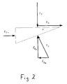
- the cooperating with the bolt 30 wedges 18 provide a Self-boosting arrangement, i. that of the electric motor 32nd introduced via the output pinion 34 in the disc brake 10 Operating force is automatically and without further, by reinforced forces to be introduced outside. To explain the self-reinforcing effect is shown in Figure 2, the balance of power reproduced on a wedge 18 shown schematically.
- the friction force or the friction torque on the brake disc depends on the relationship only from the pitch angle ⁇ , the friction coefficient ⁇ representing the disturbance variable and the input force F Ein .
- the coefficient of friction ⁇ can change relatively strongly as a function of the load on the brake. Each change in the coefficient of friction during a braking operation, however, leads to a change in the friction force F R and thus to a changing deceleration of the brake component to be braked, which in the present case is formed by the brake disk 12.
- the illustrated disc brake 10 is provided with a sensor, not shown, which allows a constant measurement of the frictional force. This known per se sensor is connected to an electronic control unit, not shown, which evaluates the signals received, and in particular makes a comparison between a predetermined desired value of the friction force and the actual actual value of the friction force. According to this evaluation of the signals of the electric motor 32 is controlled by the controller so that by rotating the first carrier ring 14 in or against the direction of rotation ⁇ an increase or decrease in the actual value of the friction force is achieved to introduce the actual value to the target value.
- the requirement of load alternation is achieved by the pitch angle ⁇ is chosen so that over the entire operating range between the motor 32 and the support ring 14 with respect to the input force F Ein either only tensile forces or only compressive forces occur, ie that the input force F A in the entire operating range either positive or negative. Due to the changing coefficient of friction ⁇ , a sign change of the input force F A would namely be possible, which leads to undesirable movements in the drive train, because then the existing drive train game is passed through and thus difficult to be regulated force jumps can occur.
- the electric motor 32 controlled such that the output gear 34 against the direction of rotation during actuation rotates, so that the first carrier ring 14 is returned to its original position, i.e. the first surfaces 20 of the wedges 18 run against the bolt 30 down and the support ring 14 moves axially from the brake disc 12 away.
- a vehicle in reverse have the wedges 18, the second surface 22 with the Pitch angle ⁇ .
- the pitch angle ⁇ of these surfaces 22 can significantly larger than the pitch angle ⁇ of the first surfaces 20 are chosen, since when reversing usually no such high friction forces are needed.
- the opposite has the Slope angle ⁇ greater pitch angle ⁇ during braking in Reverse drive an increased energy demand of the electric motor As a result, however, this circumstance has an effect because of the normal situation only low required braking force during braking in reverse does not adversely affect.
- the brake disk 12 rotates counter to the arrow ⁇ (Reverse), the change of direction, for example through the sensors of an ABS system that is usually available today can be detected, the first carrier ring 14 with Help the electric motor 32 is rotated so that the second surfaces 22 accumulate on the bolt 30. The braking process then runs as previously described.
- the brake explained in more detail as a disc brake is designed, is also an execution as a drum brake possible, wherein the wedges 18 then, for example, on the radial inner side of the drum brake shoes can be arranged. Furthermore, the self-reinforcing effect on others As can be achieved with wedges, for example with four joints.
Landscapes
- Engineering & Computer Science (AREA)
- Mechanical Engineering (AREA)
- General Engineering & Computer Science (AREA)
- Transportation (AREA)
- Braking Arrangements (AREA)
- Braking Systems And Boosters (AREA)
- Regulating Braking Force (AREA)
Applications Claiming Priority (2)
| Application Number | Priority Date | Filing Date | Title |
|---|---|---|---|
| DE19819564A DE19819564C2 (de) | 1998-04-30 | 1998-04-30 | Elektromechanische Bremse mit Selbstverstärkung |
| DE19819564 | 1998-04-30 |
Publications (3)
| Publication Number | Publication Date |
|---|---|
| EP0953785A2 EP0953785A2 (de) | 1999-11-03 |
| EP0953785A3 EP0953785A3 (de) | 2001-02-07 |
| EP0953785B1 true EP0953785B1 (de) | 2003-03-26 |
Family
ID=7866433
Family Applications (1)
| Application Number | Title | Priority Date | Filing Date |
|---|---|---|---|
| EP99107398A Expired - Lifetime EP0953785B1 (de) | 1998-04-30 | 1999-04-26 | Elektromechanische Bremse mit Selbstverstärkung |
Country Status (4)
| Country | Link |
|---|---|
| US (1) | US6318513B1 (enExample) |
| EP (1) | EP0953785B1 (enExample) |
| JP (1) | JP3902874B2 (enExample) |
| DE (2) | DE19819564C2 (enExample) |
Cited By (6)
| Publication number | Priority date | Publication date | Assignee | Title |
|---|---|---|---|---|
| DE10319082B3 (de) * | 2003-04-28 | 2004-12-16 | Estop Gmbh | Elektromechanische Bremse zum Abbremsen einer sich drehenden Komponente und Bremsanlage mit einer elektromechanischen Bremse |
| WO2006040006A1 (de) * | 2004-10-13 | 2006-04-20 | Knorr-Bremse Systeme für Nutzfahrzeuge GmbH | Scheibenbremse in selbstverstärkender bauart und ansteuerverfahren für eine selbstverstärkende bremse |
| WO2006042621A1 (de) | 2004-10-13 | 2006-04-27 | Knorr-Bremse Systeme für Nutzfahrzeuge GmbH | Scheibenbremse in selbstverstärkender bauart und ansteuerverfahren für eine selbstverstärkende bremse |
| DE102006027206A1 (de) * | 2006-06-12 | 2007-12-13 | Siemens Ag | Elektromechanische Bremse zum Abbremsen eines sich drehenden Bauteils |
| DE102006046030A1 (de) * | 2006-09-28 | 2008-04-03 | Siemens Ag | Spielfreier Antrieb für eine elektromechanische Bremsvorrichtung |
| CN101065598B (zh) * | 2004-10-13 | 2010-12-08 | 克诺尔商用车制动系统有限公司 | 按自行增力的结构形式的盘式制动器和用于自行增力的制动器的控制方法 |
Families Citing this family (118)
| Publication number | Priority date | Publication date | Assignee | Title |
|---|---|---|---|---|
| JP3740005B2 (ja) * | 1999-11-01 | 2006-01-25 | トヨタ自動車株式会社 | 制動トルク制御装置 |
| DE10005758B4 (de) * | 2000-02-09 | 2011-02-24 | Volkswagen Ag | Verfahren zur Bestimmung des Verschleißzustandes eines Bremsbelages sowie entsprechende elektromechanische Bremsenanordnung |
| GB0018154D0 (en) | 2000-07-25 | 2000-09-13 | Federal Mogul Brake Systems Li | Apparatus and method for controlling a braking system |
| DE10037055A1 (de) * | 2000-07-29 | 2002-02-14 | Bosch Gmbh Robert | Scheibenbremse |
| DE10037599A1 (de) * | 2000-08-02 | 2002-02-21 | Bosch Gmbh Robert | Trommelbremsvorrichtung |
| DE10046177A1 (de) * | 2000-09-19 | 2002-04-04 | Bosch Gmbh Robert | Scheibenbremse |
| DE10056451A1 (de) * | 2000-11-14 | 2002-05-29 | Bosch Gmbh Robert | Scheibenbremse |
| DE10104739C1 (de) * | 2001-02-02 | 2002-11-28 | Bosch Gmbh Robert | Scheibenbremse |
| DE10154178B4 (de) | 2001-05-21 | 2004-05-13 | Estop Gmbh | Elektromechanische Bremse mit Selbstverstärkung und veränderlichem Keilwinkel |
| WO2002095255A1 (de) * | 2001-05-21 | 2002-11-28 | Estop Gmbh | Elektromechanische bremse mit selbstverstärkung und veränderlichem keilwinkel |
| USD467530S1 (en) | 2001-06-29 | 2002-12-24 | Mitsubishi Denki Kabushiki Kaisha | Electromagnetic powder brake |
| USD462641S1 (en) | 2001-06-29 | 2002-09-10 | Mitsubishi Denki Kabushiki Kaisha | Electromagnetic powder brake |
| USD463340S1 (en) | 2001-06-29 | 2002-09-24 | Mitsubishi Denki Kabushiki Kaisha | Electromagnetic powder brake |
| USD463339S1 (en) | 2001-06-29 | 2002-09-24 | Mitsubishi Denki Kabushiki Kaisha | Electromagnetic powder clutch |
| USD463338S1 (en) | 2001-06-29 | 2002-09-24 | Mitsubishi Denki Kabushiki Kaisha | Electromagnetic powder brake |
| DE10149695B4 (de) * | 2001-10-09 | 2004-01-29 | Estop Gmbh | Elektromechanische Schwimmsattel-Teilbelagsscheibenbremse mit Selbstverstärkung |
| DE10151950B4 (de) * | 2001-10-22 | 2005-04-21 | Estop Gmbh | Selbstverstärkende elektromechanische Scheibenbremse mit Reibmomentermittlung |
| DE10164317C1 (de) * | 2001-12-28 | 2003-10-09 | Estop Gmbh | Selbstverstärkende elektromechanische Teilbelagscheibenbremse mit verbesserter Reibebelagführung |
| DE10201607A1 (de) * | 2002-01-16 | 2003-07-24 | Continental Teves Ag & Co Ohg | Scheibenbremse mit Betätigungsvorrichtung |
| DE10201555A1 (de) * | 2002-01-17 | 2003-08-07 | Bosch Gmbh Robert | Selbstverstärkende Reibungsbremse, Reibwertmesseinrichtung und Verfahren zur Regelung einer Bremskraft |
| DE10204947A1 (de) * | 2002-02-07 | 2003-08-21 | Zahnradfabrik Friedrichshafen | Elektromagnetisch betätigbare Reibungskupplung oder -bremse |
| DE10392252B4 (de) * | 2002-02-21 | 2011-07-14 | Haldex Brake Products Ab | Scheibenbremse |
| FR2838694B1 (fr) * | 2002-04-18 | 2004-07-09 | Bosch Gmbh Robert | Dispositif de freinage pour vehicule automobile et systeme de freinage comportant un tel dispositif |
| DE50301865D1 (de) * | 2002-04-26 | 2006-01-12 | Estop Gmbh | Kraftfahrzeugbremsanlage mit parkbremsfunktion und elektromechanische radbremse für eine solche kraftfahrzeugbremsanlage |
| DE10218825B4 (de) * | 2002-04-26 | 2004-04-29 | Estop Gmbh | Kraftfahrzeugbremsanlage mit Parkbremsfunktion und elektromechanische Bremse für eine solche Kraftfahrzeugbremsanlage |
| US6752247B2 (en) * | 2002-05-06 | 2004-06-22 | Ford Global Technologies, Llc | Method and an assembly for braking a selectively moveable assembly having a controllably varying amount of self energization |
| DE10223389A1 (de) * | 2002-05-25 | 2003-12-04 | Continental Teves Ag & Co Ohg | Reibungsbremse |
| ATE487891T1 (de) * | 2002-05-28 | 2010-11-15 | Estop Gmbh | Fehler-sicherheitskonzept für eine elektromechanische bremse mit selbstverstärkung |
| US7748793B2 (en) | 2002-05-28 | 2010-07-06 | Estop Gmbh | Fail-safe concept for an electromechanical brake |
| DE10226035A1 (de) * | 2002-06-12 | 2003-12-24 | Bosch Gmbh Robert | Bremse, insbesondere Scheibenbremse |
| DE10229455B4 (de) * | 2002-07-01 | 2005-04-21 | Estop Gmbh | Einspurfahrzeug mit elektromechanischer Scheibenbremse |
| US6932198B2 (en) * | 2002-08-07 | 2005-08-23 | Ford Global Technologies, Llc | Brake assembly and a method for braking a vehicle or another selectively movable assembly |
| DE10255192B4 (de) * | 2002-11-27 | 2015-03-19 | Robert Bosch Gmbh | Elektromechanische Bremse |
| DE10261455B8 (de) * | 2002-12-31 | 2019-05-29 | Robert Bosch Gmbh | Reibungsbremse mit Selbstverstärkung |
| DE10302516A1 (de) * | 2003-01-23 | 2004-08-05 | Robert Bosch Gmbh | Scheibenbremse mit mechanischer Selbstverstärkung |
| DE20307976U1 (de) | 2003-05-22 | 2003-07-10 | AB SKF, Göteborg/Gotenburg | Elektromagnetisch betätigte Bremsvorrichtung |
| US6959968B2 (en) * | 2003-07-02 | 2005-11-01 | Haldex Brake Products Ltd. | Central electronic control network for vehicle dynamics and ride control systems in heavy vehicles |
| US7293842B2 (en) * | 2003-07-02 | 2007-11-13 | Haldex Brake Products Ltd. | Control network for vehicle dynamics and ride control systems having distributed electronic control units |
| DE10335402A1 (de) | 2003-08-01 | 2005-02-17 | Robert Bosch Gmbh | Elektromechanische Reibungsbremse mit Selbstverstärkung |
| US6899202B1 (en) | 2003-08-13 | 2005-05-31 | Mcintyre John | Brake assembly for a bicycle |
| DE10338449A1 (de) * | 2003-08-21 | 2005-03-17 | Robert Bosch Gmbh | Fahrzeugbremsanlage |
| DE10342013A1 (de) * | 2003-09-11 | 2005-05-04 | Estop Gmbh | Reibungskupplung |
| US7096108B2 (en) * | 2003-09-26 | 2006-08-22 | Haldex Brake Products Ab | Brake system with distributed electronic control units incorporating failsafe mode |
| US7497526B2 (en) * | 2003-09-26 | 2009-03-03 | Haldex Brake Products Ab | Brake system with distributed electronic control units |
| US7448701B2 (en) | 2003-09-26 | 2008-11-11 | Haldex Brake Products Ab | System for control of brake actuator based at least in part upon tire/road friction force |
| US20050071070A1 (en) * | 2003-09-26 | 2005-03-31 | Peter Nilsson | Brake system with distributed electronic control units responsive to sensor input |
| US7347304B2 (en) * | 2003-09-26 | 2008-03-25 | Haldex Brake Products Ab | System for control of brake actuator |
| US7314257B2 (en) * | 2003-09-26 | 2008-01-01 | Haldex Brake Products Ab | Tire slip model |
| SE0302563D0 (sv) * | 2003-09-26 | 2003-09-26 | Haldex Brake Prod Ab | A parking brake mechanism for a disc brake |
| US6991302B2 (en) * | 2003-09-26 | 2006-01-31 | Haldex Brake Products Ab | Brake system with distributed electronic control units |
| US7150506B2 (en) * | 2003-09-29 | 2006-12-19 | Haldex Brake Products Ab | Control network for brake system |
| US7359786B2 (en) * | 2003-09-29 | 2008-04-15 | Haldex Brake Products Ab | Control and power supply network for vehicle braking system |
| US6984001B2 (en) * | 2003-09-29 | 2006-01-10 | Haldex Brake Products Ab | Power supply network for brake system |
| US7396088B2 (en) * | 2003-09-29 | 2008-07-08 | Haldex Brake Products Ab | Power supply network for brake system |
| DE10347792A1 (de) * | 2003-10-14 | 2005-05-12 | Bosch Gmbh Robert | Radbremse |
| DE10347942A1 (de) * | 2003-10-15 | 2005-05-19 | Robert Bosch Gmbh | Selbstverstärkende elektromechanische Scheibenbremse |
| DE10356936A1 (de) * | 2003-12-05 | 2005-06-30 | Robert Bosch Gmbh | Selbstverstärkende elektromechanische Fahrzeugbremse |
| DE10361265A1 (de) * | 2003-12-24 | 2005-07-28 | Robert Bosch Gmbh | Selbstverstärkende elektromechanische Reibungsbremse |
| US7055658B2 (en) * | 2003-12-29 | 2006-06-06 | Arvinmeritor Technology, Llc | Gain stabilizing self-energized brake mechanism |
| US20080078631A1 (en) * | 2004-02-05 | 2008-04-03 | Erlston Lester J | Disc brake in combination with brushless electric motor-generator |
| US20060260886A1 (en) * | 2004-02-05 | 2006-11-23 | Erlston Lester J | Coaxial helical brake and method of braking in lightweight brake configuration |
| DE102004008383A1 (de) * | 2004-02-20 | 2005-09-15 | Estop Gmbh | Verfahren und System zum Kompensieren einer Veränderung des Übertragungsverhaltens eines elektronischen Bremssystems |
| US20050216160A1 (en) * | 2004-03-23 | 2005-09-29 | Delphi Technologies Inc. | Method for detecting electric-mechanical-brake pad drag and/or calculating actuator efficiency |
| DE102004029841A1 (de) * | 2004-06-19 | 2006-01-05 | Robert Bosch Gmbh | Selbstverstärkende elektromechanische Reibungsbremse |
| DE102005030617A1 (de) * | 2004-10-13 | 2006-04-20 | Knorr-Bremse Systeme für Nutzfahrzeuge GmbH | Scheibenbremse in selbstverstärkender Bauart und Ansteuerverfahren für eine selbstverstärkende Bremse |
| DE102005030620A1 (de) * | 2004-10-13 | 2006-04-20 | Knorr-Bremse Systeme für Nutzfahrzeuge GmbH | Scheibenbremse in selbstverstärkerder Bauart |
| US20060253243A1 (en) * | 2005-05-06 | 2006-11-09 | Jacob Svendenius | System and method for tire/road friction estimation |
| DE102005027916B4 (de) * | 2005-06-16 | 2013-04-11 | Knorr-Bremse Systeme für Nutzfahrzeuge GmbH | Fahrzeugbremse in selbstverstärkender Bauart |
| DE102005036827B4 (de) * | 2005-08-04 | 2019-10-31 | Continental Automotive Gmbh | Sicherheitssystem einer geregelten elektromechanischen Fahrzeugbremsausrüstung |
| DE102005041098A1 (de) * | 2005-08-30 | 2007-03-08 | Siemens Ag | Gurtaufroller |
| DE102005045114B4 (de) * | 2005-09-21 | 2007-11-29 | Siemens Ag | Elektromechanisch zu betätigende selbstverstärkende Bremsvorrichtung |
| DE102005048884B3 (de) * | 2005-10-12 | 2007-05-03 | Siemens Ag | Elektromechanische Bremse mit Kraftspeicher und nachgeschalteter Kraftübersetzungseinheit |
| DE102005055295B4 (de) * | 2005-11-21 | 2014-02-13 | Continental Automotive Gmbh | Elektromechanische Bremse mit spielfreier Betätigung |
| DE102005057544B4 (de) * | 2005-12-01 | 2008-01-10 | Siemens Ag | Verfahren zum Steuern der Stromaufnahme einer selbstverstärkenden elektromechanischen Bremse |
| DE102006000763B3 (de) * | 2006-01-04 | 2007-04-12 | Siemens Ag | Elektromechanische Bremse mit Notöffnungseinrichtung |
| DE102006002254B3 (de) * | 2006-01-17 | 2007-07-05 | Siemens Ag | Selbstverstärkende Bremse mit Nockenelement |
| US20070199781A1 (en) * | 2006-02-27 | 2007-08-30 | Robert Bosch Corporation | Disc Brake |
| DE102006012440A1 (de) * | 2006-03-17 | 2007-09-20 | Siemens Ag | Bremse mit Spindel und Kurvenscheiben-Anordnung |
| US20070227837A1 (en) * | 2006-03-28 | 2007-10-04 | Akebono Corporation (North America) | Wedge roller ramp parking brake assembly |
| DE102006015034B4 (de) * | 2006-03-31 | 2010-11-18 | Continental Automotive Gmbh | Verfahren und Recheneinheit zur Bestimmung eines Leistungsparameters einer Bremse |
| DE102006015032A1 (de) * | 2006-03-31 | 2007-10-11 | Siemens Ag | Verfahren und Recheneinheit zur Bestimmung eines Reibungskoeffizienten einer Bremse |
| DE102006015741A1 (de) * | 2006-04-04 | 2007-10-11 | Robert Bosch Gmbh | Selbstverstärkende elektromechanische Teilbelagscheibenbremse |
| DE102006024710A1 (de) * | 2006-05-26 | 2007-11-29 | Siemens Ag | Bremse mit einer Kurvenscheiben-Notlösevorrichtung |
| US7630813B2 (en) * | 2006-06-06 | 2009-12-08 | Delphi Technologies, Inc. | Method for controlling electromechanical brakes using parameter identification and no additional sensors |
| DE102006034848A1 (de) * | 2006-07-27 | 2008-01-31 | Siemens Ag | Schnurbremse |
| KR101377388B1 (ko) * | 2006-08-07 | 2014-03-21 | 콘티넨탈 테베스 아게 운트 코. 오하게 | 전기기계 작동식 주차 브레이크의 조작 방법 |
| DE102006046029A1 (de) * | 2006-09-28 | 2008-04-03 | Siemens Ag | Asymmmetrische Bremsung |
| DE102006051141A1 (de) * | 2006-10-30 | 2008-05-08 | Siemens Ag | Werkzeugmaschine, Produktionsmaschine und/oder Handlingsmaschine |
| DE602006002753D1 (de) * | 2006-11-27 | 2008-10-23 | Haldex Brake Prod Ab | Scheibenbremse und Verfahren zur Erfassung der Kräfte in einer solchen Scheibenbremse |
| DE102006058565A1 (de) * | 2006-12-12 | 2008-06-19 | Siemens Ag | Ausgeglichene Keilregelung |
| ITMI20062496A1 (it) * | 2006-12-22 | 2008-06-23 | St Microelectronics Srl | Sistema di controllo per dispositivi di frenatura basato su un sensore di coppia frenante |
| US9732813B2 (en) * | 2006-12-29 | 2017-08-15 | Haldex Brake Products Ab | Park lock and pad wear adjusting arrangement for electrically actuated brake |
| DE102007003497A1 (de) | 2007-01-24 | 2008-07-31 | Siemens Ag | Gurtaufroller |
| DE102007013421A1 (de) | 2007-03-20 | 2008-09-25 | Siemens Ag | Bremseinrichtung mit einem Keilmechanismus |
| US7780567B2 (en) * | 2007-06-07 | 2010-08-24 | Gm Global Technology Operations, Inc. | Input brake assembly |
| EP2020538B8 (de) * | 2007-08-03 | 2017-08-23 | Carl Freudenberg KG | Faltenbalg für eine Bremseinrichtung |
| WO2009030726A1 (de) * | 2007-09-05 | 2009-03-12 | Continental Teves Ag & Co. Ohg | Elektromechanisch betätigbare feststellbremse für kraftfahrzeuge und verfahren zur betätigung einer solchen |
| KR100897942B1 (ko) * | 2007-09-17 | 2009-05-18 | 현대모비스 주식회사 | 주차 제동력 고정 타입 단일 모터 전자 웨지 브레이크시스템 |
| DE102007049562A1 (de) | 2007-10-16 | 2009-04-23 | Continental Automotive Gmbh | Bremse mit reversiblem Kraftspeicher |
| KR20100095540A (ko) * | 2007-11-27 | 2010-08-31 | 아스테리아 퍼포먼스 인코포레이티드 | 환형 디스크 브레이크 및 브레이크패드 제동력을 증가시키는 방법 |
| JP2009209989A (ja) * | 2008-03-03 | 2009-09-17 | Harmonic Drive Syst Ind Co Ltd | サーボモータのブレーキ装置 |
| DE102008015873A1 (de) * | 2008-03-26 | 2009-10-01 | Bombardier Transportation Gmbh | Fahrzeug, insbesondere Schienenfahrzeug, mit einer Einrichtung zur Überwachung der Bremswirkung |
| EP2123931B1 (en) * | 2008-05-21 | 2012-10-10 | KNORR-BREMSE Systeme für Nutzfahrzeuge GmbH | Parameter estimation method for self-energized brake mechanism |
| AT508296A1 (de) * | 2009-05-19 | 2010-12-15 | Ve Vienna Engineering Forschungs Und Entwicklungs Gmbh | Reibungsbremse |
| DE102009038840A1 (de) * | 2009-08-25 | 2011-03-03 | Volkswagen Ag | Sicherheitsgurteinrichtung für ein Fahrzeug |
| US9091313B2 (en) | 2013-08-27 | 2015-07-28 | Akebono Brake Corporation | Full contact brake |
| USD803117S1 (en) * | 2014-08-05 | 2017-11-21 | Freni Brembo S.P.A. | Disc brake |
| US9856934B2 (en) | 2015-12-22 | 2018-01-02 | Mahindra N.A. Tech Center | Surface ventilated disc brake rotor |
| USD789854S1 (en) * | 2015-12-22 | 2017-06-20 | Mahindra N.A. Tech Center | Disc brake rotor |
| CN106763311B (zh) * | 2017-02-15 | 2019-04-12 | 三环集团有限公司 | 一种具有间隙补偿功能的全盘式制动器 |
| CN106704419B (zh) * | 2017-02-15 | 2018-10-30 | 三环集团有限公司 | 一种盘式制动器制动力传递机构 |
| CN106763348A (zh) * | 2017-02-15 | 2017-05-31 | 三环集团有限公司 | 一种用于盘式制动器的推动机构 |
| KR101977322B1 (ko) | 2018-10-22 | 2019-05-10 | 경창산업주식회사 | 자기 강화 브레이크 캘리퍼 |
| KR102043696B1 (ko) | 2019-01-16 | 2019-11-12 | 경창산업주식회사 | 자기 강화 브레이크 캘리퍼 |
| DE102019106582A1 (de) * | 2019-03-14 | 2020-09-17 | Franka Emika Gmbh | Bremsvorrichtung für eine Antriebseinrichtung eines Roboters |
| US12031596B2 (en) | 2021-01-22 | 2024-07-09 | Kwangjin Michael Lee | Direct-acting self-energizing brake caliper |
| DE102022131384A1 (de) * | 2022-11-28 | 2024-05-29 | Schaeffler Technologies AG & Co. KG | Bremssystem |
| DE102022133457A1 (de) * | 2022-12-15 | 2024-06-20 | Schaeffler Technologies AG & Co. KG | Gekapseltes Bremssystem mit Kühlleitern und Keilgetriebe |
Family Cites Families (21)
| Publication number | Priority date | Publication date | Assignee | Title |
|---|---|---|---|---|
| GB2034834B (en) * | 1978-10-17 | 1982-11-10 | Powell R E | Disc brake assemblies |
| US4381049A (en) * | 1979-07-30 | 1983-04-26 | Goodyear Aerospace Corporation | Electrically actuated aircraft brakes |
| JPS58146723A (ja) | 1982-02-24 | 1983-09-01 | Shinko Electric Co Ltd | セルフクランプ式高伝達容量の電磁クラツチ又は電磁ブレ−キ |
| DE3304431C2 (de) * | 1983-02-09 | 1986-10-16 | Liebherr-Aero-Technik Gmbh, 8998 Lindenberg | Servobremse |
| FR2590219B1 (fr) * | 1985-11-20 | 1991-02-01 | Bendix France | Dispositif de freinage electrique pour vehicule |
| FR2605959B1 (fr) * | 1986-10-31 | 1992-01-17 | Bendix France | Dispositif de freinage pour vehicule |
| DE3709952C1 (de) * | 1987-03-26 | 1988-08-25 | Richard Dipl-Ing Wilke | Elektromotorische Bremsbetaetigungsvorrichtung fuer Schienenfahrzeuge |
| US4852699A (en) * | 1987-03-31 | 1989-08-01 | Aisin Seiki Kabushiki Kaisha | Disk brake assembly |
| FR2667410B1 (fr) * | 1990-09-28 | 1992-12-18 | Bendix Europ Services Tech | Commande electromecanique a structure centrifuge. |
| US5368137A (en) * | 1993-02-12 | 1994-11-29 | General Motors Corporation | Brake apply response control |
| ATE230824T1 (de) | 1994-07-15 | 2003-01-15 | Tyco Flow Control Pacific Pty | Aktuator |
| DE19511287B4 (de) * | 1994-07-21 | 2004-05-06 | Continental Teves Ag & Co. Ohg | Elektromechanische betätigbare Scheibenbremse |
| US5831530A (en) * | 1994-12-30 | 1998-11-03 | Lace Effect, Llc | Anti-theft vehicle system |
| US5598144A (en) * | 1994-12-30 | 1997-01-28 | Actodyne General, Inc. | Anti-theft vehicle system |
| DE19543098C2 (de) * | 1995-05-19 | 1997-03-20 | Continental Ag | Bremsaktor für elektrisch betätigbare Fahrzeugbremse |
| JP3196590B2 (ja) * | 1995-09-14 | 2001-08-06 | トヨタ自動車株式会社 | 摩擦係合装置 |
| DE19539012A1 (de) * | 1995-10-19 | 1997-04-24 | Teves Gmbh Alfred | Selbstverstärkende Reibungsbremse |
| US5706918A (en) * | 1995-12-26 | 1998-01-13 | General Motors Corporation | Brake apply mechanism |
| DE19629936C1 (de) * | 1996-07-24 | 1997-11-20 | Siemens Ag | Bremsanlage für ein Kraftfahrzeug |
| EP0929757B1 (en) | 1996-10-03 | 2003-01-29 | Toyota Jidosha Kabushiki Kaisha | Braking system including motor-driven disc brake equipped with self-servo mechanism |
| US5823636A (en) * | 1997-02-24 | 1998-10-20 | General Motors Corporation | Vehicle braking system |
-
1998
- 1998-04-30 DE DE19819564A patent/DE19819564C2/de not_active Expired - Lifetime
- 1998-08-25 US US09/140,285 patent/US6318513B1/en not_active Expired - Lifetime
- 1998-09-28 JP JP27240398A patent/JP3902874B2/ja not_active Expired - Lifetime
-
1999
- 1999-04-26 DE DE59904687T patent/DE59904687D1/de not_active Expired - Lifetime
- 1999-04-26 EP EP99107398A patent/EP0953785B1/de not_active Expired - Lifetime
Cited By (6)
| Publication number | Priority date | Publication date | Assignee | Title |
|---|---|---|---|---|
| DE10319082B3 (de) * | 2003-04-28 | 2004-12-16 | Estop Gmbh | Elektromechanische Bremse zum Abbremsen einer sich drehenden Komponente und Bremsanlage mit einer elektromechanischen Bremse |
| WO2006040006A1 (de) * | 2004-10-13 | 2006-04-20 | Knorr-Bremse Systeme für Nutzfahrzeuge GmbH | Scheibenbremse in selbstverstärkender bauart und ansteuerverfahren für eine selbstverstärkende bremse |
| WO2006042621A1 (de) | 2004-10-13 | 2006-04-27 | Knorr-Bremse Systeme für Nutzfahrzeuge GmbH | Scheibenbremse in selbstverstärkender bauart und ansteuerverfahren für eine selbstverstärkende bremse |
| CN101065598B (zh) * | 2004-10-13 | 2010-12-08 | 克诺尔商用车制动系统有限公司 | 按自行增力的结构形式的盘式制动器和用于自行增力的制动器的控制方法 |
| DE102006027206A1 (de) * | 2006-06-12 | 2007-12-13 | Siemens Ag | Elektromechanische Bremse zum Abbremsen eines sich drehenden Bauteils |
| DE102006046030A1 (de) * | 2006-09-28 | 2008-04-03 | Siemens Ag | Spielfreier Antrieb für eine elektromechanische Bremsvorrichtung |
Also Published As
| Publication number | Publication date |
|---|---|
| US6318513B1 (en) | 2001-11-20 |
| JPH11315865A (ja) | 1999-11-16 |
| DE19819564A1 (de) | 1999-12-02 |
| DE59904687D1 (de) | 2003-04-30 |
| EP0953785A2 (de) | 1999-11-03 |
| DE19819564C2 (de) | 2000-06-08 |
| JP3902874B2 (ja) | 2007-04-11 |
| EP0953785A3 (de) | 2001-02-07 |
Similar Documents
| Publication | Publication Date | Title |
|---|---|---|
| EP0953785B1 (de) | Elektromechanische Bremse mit Selbstverstärkung | |
| DE10392252B4 (de) | Scheibenbremse | |
| EP1390638B1 (de) | Elektromechanische scheibenbremse mit spielfreier betätigung | |
| EP2222977B1 (de) | Elektromechanische reibungsbremse | |
| EP1802885B1 (de) | Ansteuerverfahren für eine selbstverstärkende bremse | |
| EP1999394B1 (de) | Bremse mit spindel und kurvenscheiben-anordnung | |
| EP1692413B1 (de) | Selbstverstärkende elektromechanische fahrzeugbremse | |
| EP1322872B1 (de) | Scheibenbremse mit verstellbarer linearführung des bremsbelags | |
| EP1499813A1 (de) | Kraftfahrzeugbremsanlage mit parkbremsfunktion und elektromechanische radbremse für eine solche kraftfahrzeugbremsanlage | |
| DE19611911A1 (de) | Bremsvorrichtung | |
| EP1337764B1 (de) | Scheibenbremse mit selbstverstärkender wirkung | |
| DE19851668A1 (de) | Radbremsvorrichtung | |
| EP1802881B1 (de) | Scheibenbremse in selbstverstärkender bauart | |
| DE10218825A1 (de) | Kraftfahrzeugbremsanlage mit Parkbremsfunktion und elektromechanische Bremse für eine solche Kraftfahrzeugbremsanlage | |
| EP1963700B1 (de) | Trommelbremse | |
| EP1307666B1 (de) | Scheibenbremse | |
| DE102005030617A1 (de) | Scheibenbremse in selbstverstärkender Bauart und Ansteuerverfahren für eine selbstverstärkende Bremse | |
| DE102020208077A1 (de) | Elektrische feststellbremse mit einem eine drehmomentbegrenzungsvorrichtung umfassendes getriebe | |
| EP2005023B1 (de) | Selbstverstärkende elektromechanische teilbelagscheibenbremse | |
| EP2002141B1 (de) | Selbstverstärkende scheibenbremse und verfahren zu deren ansteuerung | |
| DE10328242A1 (de) | Fahrzeugbremse mit Selbstverstärkung | |
| DE10335402A1 (de) | Elektromechanische Reibungsbremse mit Selbstverstärkung | |
| DE10338449A1 (de) | Fahrzeugbremsanlage | |
| DE112006001595T5 (de) | Scheibenbremse | |
| WO2000076819A1 (de) | Elektromechanische radbremsvorrichtung und verfahren zum betrieb derselben |
Legal Events
| Date | Code | Title | Description |
|---|---|---|---|
| PUAI | Public reference made under article 153(3) epc to a published international application that has entered the european phase |
Free format text: ORIGINAL CODE: 0009012 |
|
| AK | Designated contracting states |
Kind code of ref document: A2 Designated state(s): DE FR GB IT |
|
| AX | Request for extension of the european patent |
Free format text: AL;LT;LV;MK;RO;SI |
|
| PUAL | Search report despatched |
Free format text: ORIGINAL CODE: 0009013 |
|
| AK | Designated contracting states |
Kind code of ref document: A3 Designated state(s): AT BE CH CY DE DK ES FI FR GB GR IE IT LI LU MC NL PT SE |
|
| AX | Request for extension of the european patent |
Free format text: AL;LT;LV;MK;RO;SI |
|
| 17P | Request for examination filed |
Effective date: 20010521 |
|
| AKX | Designation fees paid |
Free format text: DE FR GB IT |
|
| 17Q | First examination report despatched |
Effective date: 20011114 |
|
| GRAH | Despatch of communication of intention to grant a patent |
Free format text: ORIGINAL CODE: EPIDOS IGRA |
|
| GRAH | Despatch of communication of intention to grant a patent |
Free format text: ORIGINAL CODE: EPIDOS IGRA |
|
| GRAA | (expected) grant |
Free format text: ORIGINAL CODE: 0009210 |
|
| AK | Designated contracting states |
Designated state(s): DE FR GB IT |
|
| REG | Reference to a national code |
Ref country code: GB Ref legal event code: FG4D Free format text: NOT ENGLISH |
|
| GBT | Gb: translation of ep patent filed (gb section 77(6)(a)/1977) |
Effective date: 20030326 |
|
| REF | Corresponds to: |
Ref document number: 59904687 Country of ref document: DE Date of ref document: 20030430 Kind code of ref document: P |
|
| ET | Fr: translation filed | ||
| PLBE | No opposition filed within time limit |
Free format text: ORIGINAL CODE: 0009261 |
|
| STAA | Information on the status of an ep patent application or granted ep patent |
Free format text: STATUS: NO OPPOSITION FILED WITHIN TIME LIMIT |
|
| 26N | No opposition filed |
Effective date: 20031230 |
|
| REG | Reference to a national code |
Ref country code: FR Ref legal event code: PLFP Year of fee payment: 18 |
|
| REG | Reference to a national code |
Ref country code: FR Ref legal event code: PLFP Year of fee payment: 19 |
|
| REG | Reference to a national code |
Ref country code: FR Ref legal event code: PLFP Year of fee payment: 20 |
|
| PGFP | Annual fee paid to national office [announced via postgrant information from national office to epo] |
Ref country code: GB Payment date: 20180328 Year of fee payment: 20 |
|
| PGFP | Annual fee paid to national office [announced via postgrant information from national office to epo] |
Ref country code: FR Payment date: 20180320 Year of fee payment: 20 |
|
| PGFP | Annual fee paid to national office [announced via postgrant information from national office to epo] |
Ref country code: DE Payment date: 20180409 Year of fee payment: 20 |
|
| PGFP | Annual fee paid to national office [announced via postgrant information from national office to epo] |
Ref country code: IT Payment date: 20180412 Year of fee payment: 20 |
|
| REG | Reference to a national code |
Ref country code: DE Ref legal event code: R071 Ref document number: 59904687 Country of ref document: DE |
|
| REG | Reference to a national code |
Ref country code: GB Ref legal event code: PE20 Expiry date: 20190425 |
|
| PG25 | Lapsed in a contracting state [announced via postgrant information from national office to epo] |
Ref country code: GB Free format text: LAPSE BECAUSE OF EXPIRATION OF PROTECTION Effective date: 20190425 |