EP0944164B1 - Procede de commande sans detecteur et appareil pour moteur synchrone a aimant permanent - Google Patents
Procede de commande sans detecteur et appareil pour moteur synchrone a aimant permanent Download PDFInfo
- Publication number
- EP0944164B1 EP0944164B1 EP97946095A EP97946095A EP0944164B1 EP 0944164 B1 EP0944164 B1 EP 0944164B1 EP 97946095 A EP97946095 A EP 97946095A EP 97946095 A EP97946095 A EP 97946095A EP 0944164 B1 EP0944164 B1 EP 0944164B1
- Authority
- EP
- European Patent Office
- Prior art keywords
- axis
- command
- speed
- axis current
- rotation speed
- Prior art date
- Legal status (The legal status is an assumption and is not a legal conclusion. Google has not performed a legal analysis and makes no representation as to the accuracy of the status listed.)
- Expired - Lifetime
Links
- 230000001360 synchronised effect Effects 0.000 title claims description 34
- 238000000034 method Methods 0.000 title claims description 22
- 230000003247 decreasing effect Effects 0.000 claims description 4
- 238000010586 diagram Methods 0.000 description 3
- 230000010355 oscillation Effects 0.000 description 3
- 238000004804 winding Methods 0.000 description 3
- 230000004907 flux Effects 0.000 description 2
- 230000001052 transient effect Effects 0.000 description 2
- 230000003044 adaptive effect Effects 0.000 description 1
- 238000004364 calculation method Methods 0.000 description 1
- 238000006243 chemical reaction Methods 0.000 description 1
- 238000007796 conventional method Methods 0.000 description 1
- 238000013016 damping Methods 0.000 description 1
- 230000003111 delayed effect Effects 0.000 description 1
- 230000000694 effects Effects 0.000 description 1
- 238000005070 sampling Methods 0.000 description 1
- 230000009466 transformation Effects 0.000 description 1
Images

Classifications
-
- H—ELECTRICITY
- H02—GENERATION; CONVERSION OR DISTRIBUTION OF ELECTRIC POWER
- H02P—CONTROL OR REGULATION OF ELECTRIC MOTORS, ELECTRIC GENERATORS OR DYNAMO-ELECTRIC CONVERTERS; CONTROLLING TRANSFORMERS, REACTORS OR CHOKE COILS
- H02P21/00—Arrangements or methods for the control of electric machines by vector control, e.g. by control of field orientation
- H02P21/04—Arrangements or methods for the control of electric machines by vector control, e.g. by control of field orientation specially adapted for very low speeds
-
- H—ELECTRICITY
- H02—GENERATION; CONVERSION OR DISTRIBUTION OF ELECTRIC POWER
- H02P—CONTROL OR REGULATION OF ELECTRIC MOTORS, ELECTRIC GENERATORS OR DYNAMO-ELECTRIC CONVERTERS; CONTROLLING TRANSFORMERS, REACTORS OR CHOKE COILS
- H02P21/00—Arrangements or methods for the control of electric machines by vector control, e.g. by control of field orientation
- H02P21/14—Estimation or adaptation of machine parameters, e.g. flux, current or voltage
- H02P21/18—Estimation of position or speed
-
- H—ELECTRICITY
- H02—GENERATION; CONVERSION OR DISTRIBUTION OF ELECTRIC POWER
- H02P—CONTROL OR REGULATION OF ELECTRIC MOTORS, ELECTRIC GENERATORS OR DYNAMO-ELECTRIC CONVERTERS; CONTROLLING TRANSFORMERS, REACTORS OR CHOKE COILS
- H02P21/00—Arrangements or methods for the control of electric machines by vector control, e.g. by control of field orientation
- H02P21/24—Vector control not involving the use of rotor position or rotor speed sensors
- H02P21/26—Rotor flux based control
-
- H—ELECTRICITY
- H02—GENERATION; CONVERSION OR DISTRIBUTION OF ELECTRIC POWER
- H02P—CONTROL OR REGULATION OF ELECTRIC MOTORS, ELECTRIC GENERATORS OR DYNAMO-ELECTRIC CONVERTERS; CONTROLLING TRANSFORMERS, REACTORS OR CHOKE COILS
- H02P6/00—Arrangements for controlling synchronous motors or other dynamo-electric motors using electronic commutation dependent on the rotor position; Electronic commutators therefor
- H02P6/14—Electronic commutators
- H02P6/16—Circuit arrangements for detecting position
- H02P6/17—Circuit arrangements for detecting position and for generating speed information
-
- H—ELECTRICITY
- H02—GENERATION; CONVERSION OR DISTRIBUTION OF ELECTRIC POWER
- H02P—CONTROL OR REGULATION OF ELECTRIC MOTORS, ELECTRIC GENERATORS OR DYNAMO-ELECTRIC CONVERTERS; CONTROLLING TRANSFORMERS, REACTORS OR CHOKE COILS
- H02P2207/00—Indexing scheme relating to controlling arrangements characterised by the type of motor
- H02P2207/05—Synchronous machines, e.g. with permanent magnets or DC excitation
Definitions
- the present invention relates to a sensorless control method and apparatus of a permanent magnet synchronous motor which does not have a position detector and a speed detector.
- [3] is a simple method in comparison with [1], [2], moreover since the ⁇ - ⁇ axis rotating at the angular velocity substantially synchronized with the d-q axis is considered as the reference, when the deviation ⁇ e between the d-q axis and the ⁇ - ⁇ axis is small, the state equation is not complicated and the method is excellent regarding the utilization. However, since the actual value is compared with the calculated value simply introduced from the model when the ⁇ - ⁇ axis is coincident with the d-q axis, the deviation ⁇ e can not be always estimated correctly due to the modeling error.
- the magnetic axis of the synchronous machine has property of moving so as to be coincident with the current flowing direction. Consequently if the current flows in the assigned magnetic axis, after lapse of sufficient time, the magnetic axis coincides with the assigned magnetic axis. As a result, the magnetic axis can be known.
- US 5 057 759 discloses a discrete-time alternating-current motor control apparatus having a state estimation observer estimating a rotor angle and a rotor angular velocity based on a direct quadrature transformation model of the motor, wherein the gain of the observer is changed over depending on the estimated angular velocity and wherein the phase difference between the winding voltages and the winding currents supplied to the state estimation observer is compensated depending on the estimated angular velocity.
- US 5 057 759 discloses a sensorless control apparatus of a permanent magnet synchronous machine, comprising
- problems to be solved by the invention are to provide a control method and apparatus where the magnetic axis can be assigned in all speed regions and the speed can be controlled continuously irrespective of the speed command.
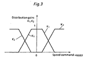
- a sensorless control method of a permanent magnet synchronous motor wherein a permanent magnet synchronous motor having a permanent magnet as a rotor is controlled in a region from zero speed to high speeds continuously, in the ⁇ - ⁇ space coordinate system where one phase is made ⁇ axis and the forward rotating direction in the electric angle - 90° from the ⁇ axis is made ⁇ axis, the coordinate d-q axis rotating in the real motor rotation speed ⁇ R is set where the magnetic axis of the motor is made d and the axis of leading in 90° from the d-axis is made q, and the ⁇ - ⁇ axis is set where the assigned magnetic axis of the motor is made ⁇ and the axis leading in 90° from the ⁇ axis is made ⁇ , characterized in that that when the rotation speed ⁇ R ⁇ of the ⁇ - ⁇ axis is determined, the distribution gain K1 is set so as to be decreased as the absolute value of the rotation speed command ⁇ RREF
- the low speed region command value i ⁇ REFL is multiplied by the distribution gain K1 and the normal speed region command value i ⁇ REFH is multiplied by the distribution gain K2 respectively, and both multiplied values are summed thereby the ⁇ axis current command value i ⁇ REF can be determined, and also the ⁇ axis current command value i ⁇ REF can be constituted by the proportion control term comprising the speed command values ⁇ REF and ⁇ RP and the integral control term comprising the speed command values ⁇ RREF and ⁇ R ⁇ .
- a sensorless control apparatus of a permanent magnet synchronous. machine comprising:
- Magnetic axis position ⁇ est(k) of the ⁇ axis assigned at the previous operation loop is used, and the three phases/two phases conversion is executed and the actual current values i ⁇ (k), i ⁇ (k) in the ⁇ - ⁇ coordinate system are led (step 2).
- Voltage commands v ⁇ REF (k), v ⁇ REF (k) converted to the ⁇ - ⁇ coordinate system and outputted at the time of (k+1) seconds are inputted (step 3).
- ⁇ - ⁇ axis current estimated values i ⁇ est (k+1), i ⁇ est (k+1) and induced voltage estimated values ⁇ ⁇ est (k+1), ⁇ ⁇ est (k+1) at the time of (k+1) Ts seconds are estimated (step 4).
- ⁇ R ⁇ est (k+1) K ⁇ ⁇ ⁇ R ⁇ sin ⁇ e
- ⁇ ⁇ est (k+1) K ⁇ ⁇ ⁇ R ⁇ cos ⁇ e
- temporary speed estimated value ⁇ R ⁇ est (k+1) is estimated (step 5).
- ⁇ R ⁇ est ( k + 1 ) sign ( ⁇ ⁇ est ( k + 1 ) ⁇ ( 1 + K ⁇ ) ⁇ ⁇ est 2 ( k + 1 ) + ⁇ ⁇ est 2 ( k + 1 ) ) K ⁇ : induced voltage constant
- ⁇ RP (k+1) to be used in the proportion control is led (step 6).
- ⁇ R P est ( k + 1 ) ⁇ R ⁇ est ( k + 1 ) + K 0 ⁇ sign ( ⁇ R ⁇ est ( k + 1 ) ) ⁇ ⁇ ⁇ est ( k + 1 ) K 0 : gain
- ⁇ est (k+1) of the ⁇ axis at the time of (k+1) Ts seconds is assigned (step 8).
- ⁇ est ( k + 1 ) ⁇ est ( k ) + ⁇ R ⁇ ( k + 1 ) ⁇ T s
- current command i ⁇ REF (k+1) of the ⁇ - ⁇ axis is led.
- current command i ⁇ REF of the T axis is led (step 9).
- i ⁇ REF ( k + 1 ) K 1 i ⁇ REF L + K 2 i ⁇ REF H
- the DC current i ⁇ REFL in the forward direction is generated to the ⁇ axis being arbitrary assigned axis
- torque being proportional to i ⁇ REFL sin ⁇ e and directed to the ⁇ axis direction is generated in the magnetic axis. Therefore if the load torque is zero, the real magnetic axis is always subjected to the torque directed to the ⁇ axis being the assigned magnetic axis.
- the damping factor is substantially zero, the d-axis produces simple harmonic oscillation around the ⁇ axis.
- the speed estimated value is fed back to the proportional control term comprising ⁇ RP thereby the transient oscillation of the d-axis is suppressed.
- the speed used for the integral is coincident with the assigned speed of the ⁇ axis, and in the low speed region where the ratio of K1 is designed larger than that of K2, since the rotation speed ⁇ R ⁇ of the ⁇ axis is near the speed command value ⁇ RREF , the d-axis being the real magnetic axis is rotated at the same speed as that of the ⁇ axis in the mean value and at the speed substantially equal to the speed command value.
- the rotation speed ⁇ R ⁇ of the ⁇ axis is coincident with the rotation speed of the d-axis in the mean value and the setting so as to correct the angle error between the ⁇ axis and the d-axis becomes possible.
- the proportional control is coincident with the speed estimated value constituting the integral control term.
- the ⁇ axis is coincident with the d-axis moreover the speed command is coincident with the speed.
- the ⁇ axis is deemed as the magnetic axis but is coincident with the d-axis, thereby the vector control is executed well.
- the distribution gain is set continuously, in the intermediate region between the low speed region and the high speed region, the error between the ⁇ axis and the d-axis is corrected gradually and the region from the low speed region to the high speed region is executed continuously in the same algorithm.
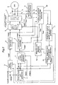
- Fig. 2 is a block diagram of the present invention.
- numeral 1 designates a distribution gain generator
- numeral 2 designates a speed controller
- numeral 3 designates ⁇ axis current command generator
- numeral 4 designates ⁇ axis current controller
- numeral 5 designates ⁇ axis current controller
- numeral 6 designates a vector control circuit
- numeral 7 designates an inverter circuit
- numeral 8 designates a synchronous motor
- numeral 9 designates a three phases/two phases converter
- numeral 10 designates ⁇ - ⁇ axis
- numeral 11 designates a proportion control speed operator
- numeral 12 designates a magnetic axis operator
- numeral 13 designates an integral, magnetic axis rotation speed operator.
- the distribution gain generator 1 produces distribution gains K1, K2 in Fig. 3.
- the ⁇ axis command i ⁇ REF is produced in that the i ⁇ REFL : low speed command, the i ⁇ REFH : high speed command and K1, K2 are inputted to the ⁇ axis current command generator 3.
- the speed controller 2 outputs the ⁇ axis current i ⁇ REF (k+1), and the ⁇ , ⁇ axes voltage commands v ⁇ REF , v ⁇ REF are outputted from the ⁇ axis current controller 4 and the ⁇ axis current controller 5 and are inputted to the vector control circuit 6.
- the output ⁇ est (k+1) from the magnetic axis operator 12 is inputted to the vector control circuit 6, and the amount of voltage and the position angle are inputted to the inverter circuit 7.
- the inverter circuit 7 supplies a current to the synchronous motor 8.
- Currents i u , i w are inputted to the three phases/two phases converter 9, and the rotor coordinate system ⁇ - ⁇ axis current is produced. This current is inputted to the ⁇ - ⁇ axis, current, induced voltage estimator 10, and also the voltage commands v ⁇ REF , v ⁇ REF are inputted.
- the induced voltage estimated values ⁇ ⁇ est (k+1), ⁇ ⁇ est (k+1) are inputted to the proportion control speed operator 11 and the command control speed ⁇ RPest is outputted.
- i ⁇ est (k+1), i ⁇ est (k+1) are inputted to the ⁇ axis current controller 4 and the ⁇ axis current controller 5, and the voltage command is produced.
- the ⁇ RPest and ⁇ RREF , and the distribution gains K1, K2 are inputted to the magnetic axis rotation speed operator 13, and the rotation speed ⁇ R ⁇ est of the magnetic axis is outputted.
- the present invention can be utilized in the field of sensorless speed control of a permanent magnet synchronous motor.
Claims (4)
- Procédé de commande sans détecteur d'un moteur synchrone à aimant permanent, dans lequel un moteur synchrone à aimant permanent ayant un aimant permanent comme rotor est commandé dans une région allant d'une vitesse nulle à une vitesse élevée en continu;
dans lequel, dans le système de coordonnées spatiales α-β où l'on désigne une phase comme axe α et l'on désigne comme axe β la direction de rotation en avant selon l'angle électrique de 90° par rapport à l'axe α, l'axe de coordonnées d-q tournant à la vitesse de rotation réelle ωR du moteur est fixé en désignant par d l'axe magnétique du moteur et par q l'axe d'attaque à 90° de l'axe d, et l'axe γ-δ est fixé en désignant par γ l'axe magnétique attribué du moteur et par δ l'axe d'attaque à 90° de l'axe γ,
caractérisé en ce que, lorsque la vitesse de rotation ωRγ de l'axe γ-δ est déterminée, le gain de distribution K1 est fixé de manière à diminuer lorsque la valeur absolue de l'ordre de vitesse de rotation ωRREF devient grande et le gain de distribution K2 est fixé de façon à augmenter lorsque la valeur absolue de l'ordre de vitesse de rotation ωRREF devient grande, et l'ordre de vitesse de rotation ωRREF est multiplié par K1 et la valeur estimée ωRP de la vitesse déterminée à partir de la tension induite du moteur synchrone ou la valeur estimée de la tension induite est multipliée par K2, respectivement, et les deux valeurs multipliées sont sommées de manière à déterminer la vitesse de rotation ωRγ de l'axe γ-δ de l'axe magnétique attribué. - Procédé de commande sans détecteur d'un moteur synchrone à aimant permanent selon la revendication 1, dans lequel, lorsque la valeur iREFL de l'ordre de courant de l'axe γ est multipliée par le gain K1 et que la valeur iγREFH de l'ordre dans la région de vitesse normale est multipliée par le gain de distribution K2, respectivement, les deux valeurs multipliées sont sommées de façon à déterminer la valeur d'ordre de courant iγREF de l'axe γ.
- Procédé de commande sans détecteur d'un moteur synchrone à aimant permanent selon la revendication 1, dans lequel la valeur d'ordre de courant iδREF de l'axe δ est constituée par le terme de commande proportionnelle comprenant les valeurs d'ordre de vitesse ωREF et ωRP et le terme de commande intégrale comprenant les valeurs d'ordre de vitesse ωRREF et ωRγ.
- Appareil de commande sans détecteur d'une machine synchrone à aimant permanent, comprenant :un générateur de gain de distribution fixant un gain de distribution K1 pour qu'il diminue lorsque la valeur absolue d'un ordre de vitesse de rotation ωRREF devient grande et un gain de distribution K2 pour qu'il augmente lorsque la valeur absolue d'un ordre de vitesse de rotation ωRREF devient grande;un générateur d'ordre de courant de l'axe γ générant l'ordre de courant iγREF de l'axe γ basé sur l'ordre de courant iγREFL de l'axe γ dans un état de faible vitesse, l'ordre de courant iγREFH de l'axe γ dans un état de vitesse élevée et les gains de distribution K1, K2;un régulateur de vitesse délivrant le courant iδREF de l'axe δ sur la base de l'ordre de vitesse de rotation ωRREF;un régulateur de courant de l'axe δ délivrant l'ordre de tension VδREF de l'axe δ sur la base du courant iδREF de l'axe δ;un régulateur de courant de l'axe γ délivrant l'ordre de courant VγREF de l'axe γ sur la base de l'ordre de courant iγREF de l'axe γ;un circuit de commande vectoriel délivrant une quantité de tension et un angle de position à un circuit inverseur du moteur synchrone sur la base de l'ordre de tension VδREF de l'axe δ et de l'ordre de tension VγREF de l'axe γ;un convertisseur trois phases/deux phases générant le courant iδ de l'axe δ et le courant iγ de l'axe γ sur la base de courants iu, iw de deux phases du moteur synchrone;un estimateur de tension induite courante de l'axe γ-δ délivrant les valeurs estimées de la tension induite εδest(k+1) et εYest(k+1) sur la base des ordres de tension vδREF, vγREF, le courant iδ de l'axe δ et le courant iγ de l'axe δ et délivrant également la valeur estimée iγest(k+1) du courant de l'axe γ au régulateur de courant de l'axe γ et la valeur estimée iδest(k+1) du courant de l'axe δ au régulateur de courant de l'axe δ, respectivement;un opérateur de vitesse de commande proportionnelle activant la vitesse de commande d'ordre ωRPest sur la base des valeurs estimées εδest(k+1), εγ est(k+1) de la tension induite;un opérateur de la vitesse de rotation de l'axe magnétique intégral délivrant la vitesse de rotation ωRγ est de l'axe magnétique sur la base des gains de distribution K1, K2 et la vitesse de commande d'ordre ωRPest ;où des moyens sont prévus pour effectuer la fonction suivante : l'ordre de vitesse de rotation ωRREF est multiplié par K1 et la valeur estimée ωRP de la vitesse déterminée à partir de la tension induite du moteur synchrone ou de la valeur estimée de la tension induite est multipliée par K2, respectivement, et les deux valeurs multipliées sont sommées de manière à déterminer la vitesse de rotation ωRγ de l'axe γ-δ de l'axe magnétique assigné; etun opérateur d'axe magnétique délivrant la quantité de tension et l'angle de position au circuit inverseur sur la base de la vitesse de rotation ωRγest de l'axe magnétique.
Applications Claiming Priority (3)
| Application Number | Priority Date | Filing Date | Title |
|---|---|---|---|
| JP32534596 | 1996-12-05 | ||
| JP8325345A JP2858692B2 (ja) | 1996-12-05 | 1996-12-05 | 永久磁石型同期電動機のセンサレス制御方法及び装置 |
| PCT/JP1997/004434 WO1998025335A1 (fr) | 1996-12-05 | 1997-12-04 | Procede de commande sans detecteur et appareil pour moteur synchrone a aimant permanent |
Publications (3)
| Publication Number | Publication Date |
|---|---|
| EP0944164A1 EP0944164A1 (fr) | 1999-09-22 |
| EP0944164A4 EP0944164A4 (fr) | 2001-03-21 |
| EP0944164B1 true EP0944164B1 (fr) | 2006-08-30 |
Family
ID=18175779
Family Applications (1)
| Application Number | Title | Priority Date | Filing Date |
|---|---|---|---|
| EP97946095A Expired - Lifetime EP0944164B1 (fr) | 1996-12-05 | 1997-12-04 | Procede de commande sans detecteur et appareil pour moteur synchrone a aimant permanent |
Country Status (8)
| Country | Link |
|---|---|
| US (1) | US6081093A (fr) |
| EP (1) | EP0944164B1 (fr) |
| JP (1) | JP2858692B2 (fr) |
| KR (1) | KR100455630B1 (fr) |
| CN (1) | CN1080950C (fr) |
| DE (1) | DE69736603T2 (fr) |
| TW (1) | TW352486B (fr) |
| WO (1) | WO1998025335A1 (fr) |
Cited By (1)
| Publication number | Priority date | Publication date | Assignee | Title |
|---|---|---|---|---|
| CN103081343A (zh) * | 2010-05-20 | 2013-05-01 | 舍弗勒技术股份两合公司 | 用于调整电换向式电机的转子位置的方法 |
Families Citing this family (63)
| Publication number | Priority date | Publication date | Assignee | Title |
|---|---|---|---|---|
| JP3944955B2 (ja) * | 1997-07-02 | 2007-07-18 | 株式会社安川電機 | 誘導電動機の誘導起電力推定方法、速度推定方法、軸ずれ補正方法及び誘導電動機制御装置 |
| AU746555B2 (en) * | 1998-10-30 | 2002-05-02 | Kabushiki Kaisha Toshiba | Apparatus for controlling synchronous motor |
| DE69916765T2 (de) * | 1998-12-18 | 2005-04-21 | Toyota Motor Co Ltd | Vorrichtung und Verfahren zur Feststellung des elektrischen Winkels und Motorregelvorrichtung |
| JP3815113B2 (ja) | 1999-04-23 | 2006-08-30 | 株式会社日立製作所 | 誘導電動機の制御方法 |
| WO2000074228A1 (fr) * | 1999-05-28 | 2000-12-07 | Kabushiki Kaisha Yaskawa Denki | Procede de commande de regime pour moteur synchrone et procede d'identification de constante |
| KR100423715B1 (ko) * | 1999-08-20 | 2004-04-03 | 미쓰비시덴키 가부시키가이샤 | 동기전동기 제어장치, 동기전동기의 제어방법 |
| US6975050B2 (en) * | 2000-01-07 | 2005-12-13 | Black & Decker Inc. | Brushless DC motor |
| WO2001052384A1 (fr) | 2000-01-07 | 2001-07-19 | Black & Decker Inc. | Moteur a courant continu sans balai |
| US6538403B2 (en) | 2000-01-07 | 2003-03-25 | Black & Decker Inc. | Brushless DC motor sensor control system and method |
| JP3673964B2 (ja) * | 2000-03-29 | 2005-07-20 | 株式会社ルネサステクノロジ | ブラシレスモータ駆動制御用半導体集積回路およびブラシレスモータ駆動制御装置 |
| JP3546817B2 (ja) * | 2000-07-11 | 2004-07-28 | 日産自動車株式会社 | 電動機の磁極位置検出装置 |
| US6492788B1 (en) * | 2000-11-10 | 2002-12-10 | Otis Elevator Company | Method and apparatus for encoderless operation of a permanent magnet synchronous motor in an elevator |
| JP3692046B2 (ja) * | 2001-03-16 | 2005-09-07 | 株式会社東芝 | モータ制御装置 |
| EP1303035B1 (fr) * | 2001-04-24 | 2016-08-17 | Mitsubishi Denki Kabushiki Kaisha | Système de contrôle d'un moteur synchronisé |
| WO2002091559A1 (fr) * | 2001-05-09 | 2002-11-14 | Hitachi, Ltd. | Systeme d'entrainement pour moteur synchrone |
| KR100428505B1 (ko) | 2001-07-06 | 2004-04-28 | 삼성전자주식회사 | 유도전동기의 속도 및 회전자 자속 추정방법 |
| KR100421376B1 (ko) * | 2001-07-10 | 2004-03-09 | 엘지전자 주식회사 | 동기 릴럭턴스 모터의 회전 속도 제어장치 |
| DE60223690T2 (de) | 2001-08-02 | 2008-10-30 | Siemens Vdo Automotive Corporation, Auburn Hills | Verfahren und gerät zur drehzahlregelung eines hochdynamischen dauermagneterregten motors mit eingeschränkter lageinformation |
| JP3668870B2 (ja) * | 2001-08-09 | 2005-07-06 | 株式会社日立製作所 | 同期電動機駆動システム |
| JP2003079200A (ja) * | 2001-09-04 | 2003-03-14 | Hitachi Ltd | 電動機駆動システム |
| JP2003111480A (ja) * | 2001-09-28 | 2003-04-11 | Matsushita Electric Ind Co Ltd | 電動機駆動装置 |
| JP3931079B2 (ja) * | 2001-12-14 | 2007-06-13 | 松下電器産業株式会社 | 電動機駆動装置及びそれを用いた冷凍装置 |
| US6762573B2 (en) * | 2002-02-26 | 2004-07-13 | General Motors Corporation | System and method for estimating rotor position of a permanent magnet motor |
| CA2379732A1 (fr) | 2002-04-02 | 2003-10-02 | Turbocor Inc. | Systeme et methode de commande d'un moteur electrique |
| JP3812739B2 (ja) * | 2002-05-28 | 2006-08-23 | 三菱電機株式会社 | モータ異常検出装置及び電動パワーステアリング制御装置 |
| KR100484818B1 (ko) * | 2002-10-10 | 2005-04-22 | 엘지전자 주식회사 | 동기 릴럭턴스 모터의 센서리스 제어시스템 |
| KR100511274B1 (ko) * | 2002-11-08 | 2005-08-31 | 엘지전자 주식회사 | 영구자석형 동기모터의 센서리스 제어방법 |
| US20040100221A1 (en) * | 2002-11-25 | 2004-05-27 | Zhenxing Fu | Field weakening with full range torque control for synchronous machines |
| US20040100220A1 (en) * | 2002-11-25 | 2004-05-27 | Zhenxing Fu | Weighted higher-order proportional-integral current regulator for synchronous machines |
| US6756753B1 (en) * | 2002-12-11 | 2004-06-29 | Emerson Electric Co. | Sensorless control system and method for a permanent magnet rotating machine |
| JP4230276B2 (ja) * | 2003-05-19 | 2009-02-25 | 本田技研工業株式会社 | ブラシレスdcモータの制御装置 |
| DE10338996A1 (de) * | 2003-08-25 | 2005-03-24 | Trw Fahrwerksysteme Gmbh & Co. Kg | Verfahren zur Steuerung eines bürstenlosen Elektromotors |
| DE10339028A1 (de) * | 2003-08-25 | 2005-03-31 | Siemens Ag | Verfahren und Vorrichtung zum Steuern eines bürstenlosen Gleichstrommotors |
| KR100665061B1 (ko) | 2004-12-08 | 2007-01-09 | 삼성전자주식회사 | 모터의 속도 제어장치 및 속도 제어방법 |
| US7342379B2 (en) | 2005-06-24 | 2008-03-11 | Emerson Electric Co. | Sensorless control systems and methods for permanent magnet rotating machines |
| US7208895B2 (en) * | 2005-06-24 | 2007-04-24 | Emerson Electric Co. | Control systems and methods for permanent magnet rotating machines |
| US7495404B2 (en) * | 2005-08-17 | 2009-02-24 | Honeywell International Inc. | Power factor control for floating frame controller for sensorless control of synchronous machines |
| JP4879657B2 (ja) * | 2006-05-31 | 2012-02-22 | 本田技研工業株式会社 | 電動機の制御装置 |
| JP4770732B2 (ja) * | 2006-12-27 | 2011-09-14 | 株式会社デンソー | モータの制御方法およびその装置 |
| US7535684B2 (en) * | 2007-01-09 | 2009-05-19 | Honeywell International Inc. | Overspeed protection for sensorless electric drives |
| GB0803279D0 (en) | 2008-02-22 | 2008-04-02 | Univ Gent | Sensorless control of salient pole machines |
| JP4751435B2 (ja) * | 2008-10-09 | 2011-08-17 | 株式会社東芝 | モータ磁極位置検出装置,モータ制御装置,モータ駆動システム及び洗濯機 |
| JP2010095075A (ja) * | 2008-10-15 | 2010-04-30 | Jtekt Corp | 車両用操舵装置 |
| US8264192B2 (en) | 2009-08-10 | 2012-09-11 | Emerson Climate Technologies, Inc. | Controller and method for transitioning between control angles |
| JP2012100369A (ja) * | 2010-10-29 | 2012-05-24 | Hitachi Appliances Inc | 冷凍装置および永久磁石同期モータの制御装置 |
| WO2013125034A1 (fr) | 2012-02-24 | 2013-08-29 | 株式会社安川電機 | Appareil de commande de moteur |
| US9634593B2 (en) | 2012-04-26 | 2017-04-25 | Emerson Climate Technologies, Inc. | System and method for permanent magnet motor control |
| CN102769425B (zh) * | 2012-07-16 | 2014-08-27 | 电子科技大学 | 一种基于mras和模糊控制的永磁同步电机控制方法 |
| US9219432B2 (en) * | 2012-07-25 | 2015-12-22 | System General Corporation | Control systems and methods for angle estimation of permanent magnet motors |
| JP5761243B2 (ja) * | 2013-03-29 | 2015-08-12 | 株式会社安川電機 | モータ制御装置および磁極位置推定方法 |
| JP6307223B2 (ja) * | 2013-04-26 | 2018-04-04 | 日立オートモティブシステムズ株式会社 | 三相同期電動機の制御装置及びそれを用いた三相同期電機駆動システム、一体型電動機システム、ポンプシステム、及び圧縮機システム、並びに三相同期電動機の制御方法 |
| CN103312255B (zh) * | 2013-06-18 | 2015-06-03 | 山东大学(威海) | 一种永磁同步电机速度控制方法和装置 |
| CN103346727B (zh) * | 2013-07-27 | 2016-01-20 | 湖北立锐机电有限公司 | 应用于pmsm无位置控制的角度跟踪观测器及其实现方法 |
| CN103501148A (zh) * | 2013-09-24 | 2014-01-08 | 江苏大学 | 一种无轴承永磁同步电机无径向位移传感器运行控制方法 |
| CN104539211B (zh) * | 2014-12-18 | 2017-08-01 | 珠海格力节能环保制冷技术研究中心有限公司 | 电机参数辨识方法及装置 |
| CN106160594B (zh) * | 2015-04-27 | 2019-01-11 | 比亚迪股份有限公司 | 用于永磁同步电机零位测量的方法及系统 |
| CN104901600B (zh) * | 2015-05-19 | 2017-10-27 | 南京航空航天大学 | 宽转速范围内永磁同步电机的无位置传感器控制方法 |
| CN104953904A (zh) * | 2015-07-07 | 2015-09-30 | 上海中科深江电动车辆有限公司 | 永磁同步电机弱磁控制方法及装置 |
| CN105932922B (zh) * | 2016-06-20 | 2018-08-07 | 华北电力大学(保定) | 一种机械弹性储能用永磁同步发电机的控制方法 |
| JP6623987B2 (ja) * | 2016-09-09 | 2019-12-25 | 株式会社デンソー | シフトレンジ制御装置 |
| CN106330020B (zh) * | 2016-11-03 | 2018-12-11 | 四川长虹电器股份有限公司 | 电机启动平稳过渡控制方法 |
| CN108462425B (zh) * | 2018-01-24 | 2020-01-21 | 深圳市海浦蒙特科技有限公司 | 单相电机的变频调速控制方法及系统 |
| US11404984B2 (en) * | 2018-06-20 | 2022-08-02 | Steering Solutions Ip Holding Corporation | Parameter learning for permanent magnet synchronous motor drives |
Family Cites Families (10)
| Publication number | Priority date | Publication date | Assignee | Title |
|---|---|---|---|---|
| JPH0270282A (ja) * | 1988-09-06 | 1990-03-09 | Mitsubishi Electric Corp | インバータ装置 |
| JPH02219498A (ja) * | 1989-02-16 | 1990-09-03 | Toyota Central Res & Dev Lab Inc | インバータの電流制御装置 |
| JPH0349588A (ja) * | 1989-07-14 | 1991-03-04 | Omron Corp | 離散時間型acモータ制御装置 |
| JPH0755080B2 (ja) * | 1989-09-29 | 1995-06-07 | 譲 常広 | インバータの制御装置 |
| US5182508A (en) * | 1992-04-16 | 1993-01-26 | Westinghouse Electric Corp. | Reconfigurable AC induction motor drive for battery-powered vehicle |
| JPH0787800A (ja) * | 1993-09-13 | 1995-03-31 | Meidensha Corp | インバータの自動トルクブースト制御およびすべり補償制御装置 |
| US5585709A (en) * | 1993-12-22 | 1996-12-17 | Wisconsin Alumni Research Foundation | Method and apparatus for transducerless position and velocity estimation in drives for AC machines |
| JPH08280199A (ja) * | 1995-02-10 | 1996-10-22 | Nippon Soken Inc | 永久磁石界磁同期電動機のセンサレス制御装置 |
| EP0748038B1 (fr) * | 1995-06-05 | 2002-08-21 | Kollmorgen Corporation | Système et méthode de commande de moteurs à aimants permanents sans balais |
| JP3253004B2 (ja) * | 1996-01-12 | 2002-02-04 | 株式会社安川電機 | 永久磁石形同期電動機の速度推定方法及びその回転子ずれ角推定方法並びに回転子位置修正方法 |
-
1996
- 1996-12-05 JP JP8325345A patent/JP2858692B2/ja not_active Expired - Fee Related
-
1997
- 1997-12-02 TW TW086118120A patent/TW352486B/zh not_active IP Right Cessation
- 1997-12-04 DE DE69736603T patent/DE69736603T2/de not_active Expired - Fee Related
- 1997-12-04 KR KR10-1999-7004929A patent/KR100455630B1/ko not_active IP Right Cessation
- 1997-12-04 WO PCT/JP1997/004434 patent/WO1998025335A1/fr active IP Right Grant
- 1997-12-04 EP EP97946095A patent/EP0944164B1/fr not_active Expired - Lifetime
- 1997-12-04 US US09/308,919 patent/US6081093A/en not_active Expired - Lifetime
- 1997-12-04 CN CN97180338A patent/CN1080950C/zh not_active Expired - Fee Related
Cited By (1)
| Publication number | Priority date | Publication date | Assignee | Title |
|---|---|---|---|---|
| CN103081343A (zh) * | 2010-05-20 | 2013-05-01 | 舍弗勒技术股份两合公司 | 用于调整电换向式电机的转子位置的方法 |
Also Published As
| Publication number | Publication date |
|---|---|
| KR100455630B1 (ko) | 2004-11-06 |
| EP0944164A4 (fr) | 2001-03-21 |
| CN1080950C (zh) | 2002-03-13 |
| CN1240064A (zh) | 1999-12-29 |
| KR20000057380A (ko) | 2000-09-15 |
| EP0944164A1 (fr) | 1999-09-22 |
| DE69736603T2 (de) | 2007-09-20 |
| TW352486B (en) | 1999-02-11 |
| US6081093A (en) | 2000-06-27 |
| DE69736603D1 (de) | 2006-10-12 |
| WO1998025335A1 (fr) | 1998-06-11 |
| JPH10174499A (ja) | 1998-06-26 |
| JP2858692B2 (ja) | 1999-02-17 |
Similar Documents
| Publication | Publication Date | Title |
|---|---|---|
| EP0944164B1 (fr) | Procede de commande sans detecteur et appareil pour moteur synchrone a aimant permanent | |
| JP3411878B2 (ja) | 同期モータの回転子位置推定方法、位置センサレス制御方法及び制御装置 | |
| JP4674525B2 (ja) | 磁極位置推定方法及びモータ制御装置 | |
| EP1755212B1 (fr) | Commande du facteur de puissance pour contrôleur à cadre flottant pour la commande sans capteurs des machines synchrones | |
| Schroedl et al. | Sensorless control of reluctance machines at arbitrary operating conditions including standstill | |
| EP0748038B1 (fr) | Système et méthode de commande de moteurs à aimants permanents sans balais | |
| JP3467961B2 (ja) | 回転電機の制御装置 | |
| JP5130031B2 (ja) | 永久磁石モータの位置センサレス制御装置 | |
| JP4989075B2 (ja) | 電動機駆動制御装置及び電動機駆動システム | |
| KR101046802B1 (ko) | 교류 회전기의 제어 장치 및 이 제어 장치를 사용한 교류회전기의 전기적 정수 측정 방법 | |
| US20030128009A1 (en) | Motor control apparatus and method | |
| JP2002095300A (ja) | 永久磁石同期電動機の制御方法 | |
| JP2001204190A (ja) | 初期磁極位置推定装置その誤差調整方法 | |
| JP3253004B2 (ja) | 永久磁石形同期電動機の速度推定方法及びその回転子ずれ角推定方法並びに回転子位置修正方法 | |
| US6940251B1 (en) | Decoupling of cross coupling for floating reference frame controllers for sensorless control of synchronous machines | |
| EP2493067B1 (fr) | Procédé et appareil pour estimer l'angle de rotor d'un moteur à réluctance synchrone | |
| EP1755211B1 (fr) | Estimation de resistance d'un moteur électric à courant alternatif | |
| EP1681762A2 (fr) | Système de contrôle de moteur synchrone et procédé | |
| JP2002136197A (ja) | センサレスベクトル制御装置およびその方法 | |
| JP3797508B2 (ja) | 永久磁石型同期電動機のセンサレス速度制御方法及びその脱調検出方法 | |
| Pyrhönen | Analysis and control of excitation, field weakening and stability in direct torque controlled electrically excited synchronous motor drives | |
| JP3674638B2 (ja) | 誘導電動機の速度推定方法および誘導電動機駆動装置 | |
| JP4061446B2 (ja) | 同期電動機の抵抗値同定方法とその制御装置 | |
| JP2003088166A (ja) | Ac同期モータの初期磁極推定装置 | |
| JP3161237B2 (ja) | 誘導電動機制御装置 |
Legal Events
| Date | Code | Title | Description |
|---|---|---|---|
| PUAI | Public reference made under article 153(3) epc to a published international application that has entered the european phase |
Free format text: ORIGINAL CODE: 0009012 |
|
| 17P | Request for examination filed |
Effective date: 19990702 |
|
| AK | Designated contracting states |
Kind code of ref document: A1 Designated state(s): DE GB NL |
|
| A4 | Supplementary search report drawn up and despatched |
Effective date: 20010206 |
|
| AK | Designated contracting states |
Kind code of ref document: A4 Designated state(s): DE GB NL |
|
| RIC1 | Information provided on ipc code assigned before grant |
Free format text: 7H 02P 5/408 A, 7H 02P 21/00 B |
|
| 17Q | First examination report despatched |
Effective date: 20040603 |
|
| GRAP | Despatch of communication of intention to grant a patent |
Free format text: ORIGINAL CODE: EPIDOSNIGR1 |
|
| GRAS | Grant fee paid |
Free format text: ORIGINAL CODE: EPIDOSNIGR3 |
|
| GRAA | (expected) grant |
Free format text: ORIGINAL CODE: 0009210 |
|
| AK | Designated contracting states |
Kind code of ref document: B1 Designated state(s): DE GB NL |
|
| REG | Reference to a national code |
Ref country code: GB Ref legal event code: FG4D |
|
| RIC1 | Information provided on ipc code assigned before grant |
Ipc: H02P 21/00 20060101ALI20060721BHEP Ipc: H02P 6/20 20060101AFI20060721BHEP |
|
| REF | Corresponds to: |
Ref document number: 69736603 Country of ref document: DE Date of ref document: 20061012 Kind code of ref document: P |
|
| PLBE | No opposition filed within time limit |
Free format text: ORIGINAL CODE: 0009261 |
|
| STAA | Information on the status of an ep patent application or granted ep patent |
Free format text: STATUS: NO OPPOSITION FILED WITHIN TIME LIMIT |
|
| 26N | No opposition filed |
Effective date: 20070531 |
|
| PGFP | Annual fee paid to national office [announced via postgrant information from national office to epo] |
Ref country code: NL Payment date: 20081215 Year of fee payment: 12 |
|
| PGFP | Annual fee paid to national office [announced via postgrant information from national office to epo] |
Ref country code: DE Payment date: 20081127 Year of fee payment: 12 |
|
| PGFP | Annual fee paid to national office [announced via postgrant information from national office to epo] |
Ref country code: GB Payment date: 20081203 Year of fee payment: 12 |
|
| REG | Reference to a national code |
Ref country code: NL Ref legal event code: V1 Effective date: 20100701 |
|
| GBPC | Gb: european patent ceased through non-payment of renewal fee |
Effective date: 20091204 |
|
| PG25 | Lapsed in a contracting state [announced via postgrant information from national office to epo] |
Ref country code: NL Free format text: LAPSE BECAUSE OF NON-PAYMENT OF DUE FEES Effective date: 20100701 |
|
| PG25 | Lapsed in a contracting state [announced via postgrant information from national office to epo] |
Ref country code: DE Free format text: LAPSE BECAUSE OF NON-PAYMENT OF DUE FEES Effective date: 20100701 |
|
| PG25 | Lapsed in a contracting state [announced via postgrant information from national office to epo] |
Ref country code: GB Free format text: LAPSE BECAUSE OF NON-PAYMENT OF DUE FEES Effective date: 20091204 |