EP0901191A2 - Interconnexion en tresse tissée - Google Patents
Interconnexion en tresse tissée Download PDFInfo
- Publication number
- EP0901191A2 EP0901191A2 EP19980307198 EP98307198A EP0901191A2 EP 0901191 A2 EP0901191 A2 EP 0901191A2 EP 19980307198 EP19980307198 EP 19980307198 EP 98307198 A EP98307198 A EP 98307198A EP 0901191 A2 EP0901191 A2 EP 0901191A2
- Authority
- EP
- European Patent Office
- Prior art keywords
- array
- wires
- woven mesh
- strands
- mesh interconnect
- Prior art date
- Legal status (The legal status is an assumption and is not a legal conclusion. Google has not performed a legal analysis and makes no representation as to the accuracy of the status listed.)
- Granted
Links
Images


Classifications
-
- H—ELECTRICITY
- H01—ELECTRIC ELEMENTS
- H01R—ELECTRICALLY-CONDUCTIVE CONNECTIONS; STRUCTURAL ASSOCIATIONS OF A PLURALITY OF MUTUALLY-INSULATED ELECTRICAL CONNECTING ELEMENTS; COUPLING DEVICES; CURRENT COLLECTORS
- H01R13/00—Details of coupling devices of the kinds covered by groups H01R12/70 or H01R24/00 - H01R33/00
- H01R13/02—Contact members
- H01R13/22—Contacts for co-operating by abutting
- H01R13/24—Contacts for co-operating by abutting resilient; resiliently-mounted
- H01R13/2464—Contacts for co-operating by abutting resilient; resiliently-mounted characterized by the contact point
- H01R13/2492—Contacts for co-operating by abutting resilient; resiliently-mounted characterized by the contact point multiple contact points
-
- H—ELECTRICITY
- H05—ELECTRIC TECHNIQUES NOT OTHERWISE PROVIDED FOR
- H05K—PRINTED CIRCUITS; CASINGS OR CONSTRUCTIONAL DETAILS OF ELECTRIC APPARATUS; MANUFACTURE OF ASSEMBLAGES OF ELECTRICAL COMPONENTS
- H05K1/00—Printed circuits
- H05K1/02—Details
- H05K1/03—Use of materials for the substrate
- H05K1/038—Textiles
-
- H—ELECTRICITY
- H05—ELECTRIC TECHNIQUES NOT OTHERWISE PROVIDED FOR
- H05K—PRINTED CIRCUITS; CASINGS OR CONSTRUCTIONAL DETAILS OF ELECTRIC APPARATUS; MANUFACTURE OF ASSEMBLAGES OF ELECTRICAL COMPONENTS
- H05K2201/00—Indexing scheme relating to printed circuits covered by H05K1/00
- H05K2201/02—Fillers; Particles; Fibers; Reinforcement materials
- H05K2201/0275—Fibers and reinforcement materials
- H05K2201/0281—Conductive fibers
-
- H—ELECTRICITY
- H05—ELECTRIC TECHNIQUES NOT OTHERWISE PROVIDED FOR
- H05K—PRINTED CIRCUITS; CASINGS OR CONSTRUCTIONAL DETAILS OF ELECTRIC APPARATUS; MANUFACTURE OF ASSEMBLAGES OF ELECTRICAL COMPONENTS
- H05K2201/00—Indexing scheme relating to printed circuits covered by H05K1/00
- H05K2201/02—Fillers; Particles; Fibers; Reinforcement materials
- H05K2201/0275—Fibers and reinforcement materials
- H05K2201/029—Woven fibrous reinforcement or textile
-
- Y—GENERAL TAGGING OF NEW TECHNOLOGICAL DEVELOPMENTS; GENERAL TAGGING OF CROSS-SECTIONAL TECHNOLOGIES SPANNING OVER SEVERAL SECTIONS OF THE IPC; TECHNICAL SUBJECTS COVERED BY FORMER USPC CROSS-REFERENCE ART COLLECTIONS [XRACs] AND DIGESTS
- Y10—TECHNICAL SUBJECTS COVERED BY FORMER USPC
- Y10T—TECHNICAL SUBJECTS COVERED BY FORMER US CLASSIFICATION
- Y10T442/00—Fabric [woven, knitted, or nonwoven textile or cloth, etc.]
- Y10T442/10—Scrim [e.g., open net or mesh, gauze, loose or open weave or knit, etc.]
- Y10T442/102—Woven scrim
- Y10T442/107—Comprising at least two chemically different fibers
-
- Y—GENERAL TAGGING OF NEW TECHNOLOGICAL DEVELOPMENTS; GENERAL TAGGING OF CROSS-SECTIONAL TECHNOLOGIES SPANNING OVER SEVERAL SECTIONS OF THE IPC; TECHNICAL SUBJECTS COVERED BY FORMER USPC CROSS-REFERENCE ART COLLECTIONS [XRACs] AND DIGESTS
- Y10—TECHNICAL SUBJECTS COVERED BY FORMER USPC
- Y10T—TECHNICAL SUBJECTS COVERED BY FORMER US CLASSIFICATION
- Y10T442/00—Fabric [woven, knitted, or nonwoven textile or cloth, etc.]
- Y10T442/10—Scrim [e.g., open net or mesh, gauze, loose or open weave or knit, etc.]
- Y10T442/102—Woven scrim
- Y10T442/109—Metal or metal-coated fiber-containing scrim
- Y10T442/131—Including a coating or impregnation of synthetic polymeric material
Definitions
- the present invention relates generally to conductive elastomers and more particularly to a woven mesh interconnect.
- Conductive elastomers are known in the art.
- a conductive elastomer typically comprises a non-conductive elastomeric material which has a plurality of conductive particles or flakes disposed therein.
- the conductive flakes or particles make an electrical connection between a device such as a packaged integrated circuit and a circuit board having electrically conductive pads or traces when the elastomer is placed between the device and the circuit board.
- the current carrying capacity of such an elastomer is small due to the resulting high resistance connection provided by the conductive particles of the elastomer. Further, the integrity of the connection varies from device to device since the concentration of conductive particles varies from contact to contact.
- Some other conductive elastomers that are known are formed by encapsulating a plurality of conductive wires within an elastomeric material. These conductive elastomers are limited in the number of wires, the wire pitch and the number of rows of wires that can be used. These conductive elastomers also suffer from electrical and mechanical integrity problems. The wire in these elastomers require inherently high forces to assure electrical connection. Further, these wire elastomer designs exhibit a relatively large permanent deformation upon initial compression or once compressed they do not recover to the approximate initial starting height, which is referred to as compression set.
- An electrical interconnect is comprised of a woven mesh in which an array of parallel wires is retained in spaced relation by a transverse array of nonconducting strands, the mesh being enclosed or encased within a resilient matrix.
- the conductive wires are on a close pitch such that a great number of wires are in contact with each contact pad to yield greater current carrying capacity and corresponding lower resistance. The closer pitch wires also provide greater redundancy of contact points.
- This structure can be custom configured in as many layers or in a variety of shapes as is desirable to achieve a given electrical performance or to suit an intended application.
- the woven mesh can be wrapped around a shaped substrate to provide electrical connections in a desired shape.
- the woven mesh interconnect can be integrated as part of a boot, wherein the boot receives an electrical device therein and the woven mesh interconnect provides electrical connection from the device within the boot to outside the boot.
- the woven mesh interconnect can be layered and shaped to form an interconnect which not only provides electrical interconnection but also provides a biasing force due to the shape of the device.
- An electrical interconnect is comprised of a woven mesh in which an array of parallel wires is retained in spaced relation by a transverse array of nonconducting strands, the mesh being enclosed or encased within a resilient matrix.
- the structures described herein are of non-adhesive construction; that is, the wires are directly imbedded within the elastomeric matrix.
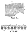
- the woven mesh 10 comprises a first array of conductive wires 20 which are generally parallel with each other.
- the woven mesh further includes a second array of strands 30 which are nonconductive and are generally parallel with each other.
- the first array of conductive wires is disposed generally transverse with respect to the second array of strands, and are interwoven with the second array of strands.
- a single strand from the second array of strands is disposed such that the strand 30 weaves below one conductive wire 20 of the first array of wires, and then weaves above the adjacent wire of the array.
- the strand thus alternates being disposed above and below adjacent wires of the first array.
- a next strand of the array also alternates between being disposed above and below adjacent wires, but in an opposite position as an adjacent strand.
- a first strand may be above a first wire, below a second wire, above a third wire etc., while an adjacent strand would be below the first wire, above the second wire, below the third wire, etc.
- the wires 20 weave below and above the strands 30 and alternate weaving in an opposite position as an adjacent wire. Accordingly, the two arrays are interlaced and interwoven within each other forming the woven mesh.
- alternate weaving variations can be used, such as, weaving between every two wires and strands, every three wires and strands, etc. and any combination thereof.
- the wires 20 are comprised of any conductive material and preferably of nickel, and most preferably of gold plated nickel.
- the strands 30 are comprised of a non-conductive material and preferably of polyester.
- the densities of wires and strands could be any density that forms a mesh, but most particularly about 300 wires per inch for the first array of wires and approximately 80 strands per inch for the second array of strands.
- the wires and the strands each have a respective diameter of approximately 0.04 mm.
- the woven mesh interconnect 50 further includes a matrix 40 for maintaining the spaced relation of the array of wires 20 with respect to each other and with respect to the interwoven array of strands 30.
- the matrix 40 is nonconductive and typically comprises a resilient material such as silicone rubber.
- the matrix 40 encloses the woven mesh 10, with the end surfaces of the matrix having the ends of the first array of wires exposed such that an electrical and mechanical interconnect can be provided from a first end of the woven mesh interconnect 50 to an opposite end of the woven mesh interconnect 50. Two or more rows of mesh 10 can be provided within the same matrix to achieve greater redundancy of contacts.
- the woven mesh interconnect 50 provides electrical conduction along an entire side of the elastomeric matrix.
- the matrix 40 as shown in Fig. 1B allows the wires 20 to protrude through one side of the elastomeric material 40, whereby electrical contact is made along the entire side of the matrix 40 by contacting the protruding portions of the weaving wires 20, which extend through the elastomeric matrix 40.
- This embodiment is well suited for making 90° connections and where a wrap around connection is desired.
- the wires 20 can be exposed at the ends or encased within the elastomeric material.
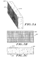
- the multilayered sheet 100 includes three layers 51, 52, and 53 of woven mesh interconnect 50. All three layers are oriented similarly in that the array of wires of the woven mesh 10 in each layer is positioned in the same direction. While three layers are shown, it should be appreciated that any number of layers could be utilized. The sheets or webs can then be cut to intended sizes for use.
- the layers here are shown aligned such that the array of wires are running in the same direction on each sheet, it should be appreciated that the layers could be alternating in their alignment such that a first layer is oriented with the array of wires running in a first direction and a second layer is oriented with the array of wires running in a transverse direction with respect to the array of wires of the first layer.
- electrical connections are provided from a first horizontal edge of the sheet 100 to a second horizontal edge, and from a first vertical edge to a second vertical edge, while the connections of the vertical edge are isolated from the connections of the horizontal edge.
- the woven mesh interconnect comprises a single layer of woven mesh 50, laminated on each side by a nonconductive layer of material 60.
- the woven mesh is oriented such that the array of wires 20 extend from a first horizontal or top side 91 to the opposing horizontal or bottom side 92. Further, the woven mesh in this instance comprises two arrays of conductive wires 20 within the same matrix.
- an interconnect 200 is shown in which two separate rows of conductive mesh 220 are used in a sheet, and additional rows may be used to suit particular contact requirements.
- the conductive wires are on a close pitch to yield greater current carrying capacity and achieve a lower more stable resistance.
- the closer pitch wires provide greater redundancy of contact points.
- This structure can be custom configured in as many layers as is desirable to achieve a given electrical performance.
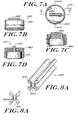
- a further embodiment 300 is shown wherein the woven mesh interconnect 310 is attached to a piece of insulative material 340 such as an elastomeric foam.
- the woven mesh interconnect in this embodiment has a very thin matrix, such that the resulting woven mesh interconnect is very pliable and acts like a skin wherein it can be layered on the insulative foam or easily deformed into other shapes.
- the embodiment 400 comprises a wire mesh interconnect 410 which is wrapped around and bonded to an elastomeric substrate 440.
- the substrate 440 is comprised of a non-conductive material such as silicone rubber.
- the silicone rubber matrix of the mesh 410 can be integrally bonded to the substrate 440 to form an essentially integral or unitary rubber core containing an outer wrapping of embedded conductors to provide an interconnect between the opposing edge surfaces.
- the mesh 410 can be attached to the substrate at predetermined points, and is thus flexible with respect to the substrate.
- the woven mesh interconnect 550 can be incorporated into a boot 560 or other housing which retains an electrical device 570 such as a microphone.
- an electrical device 570 such as a microphone.
- a rubber or other elastomeric material boot 560 which includes an opening for retaining a device 570 such as a microphone and having the mesh interconnect 550 for providing electrical interconnection from the device 570 to external circuitry.
- the elastomeric structure 500 provides a convenient unitary subassembly for easy mounting within a cellular telephone, for example.
- the wire mesh 610 can be layered within a generally X-shaped elastomeric structure as shown in the drawing to provide conductive interconnection via the nickel or other metal wires from the outer surface of one lobe of the X-shaped structure to the outer surface of the opposing lobe.
- the wire mesh 610 can create a conductive interconnection between lobe A and lobe C of the X-shaped structure 600 and a conductive interconnection between lobe B and lobe D of structure 600.
- the non-conductive resilient or elastomeric material 640 besides filling space between the wires of the conductive wire mesh 610, creates a space through the center of the X-shaped structure 600, which separates the conductive pathways created by the interconnections between lobes A and C and lobes B and D.
- the resilient or elastomeric material 640 also serves to provide a biasing force against spaced elements being conductively interconnected to provide good contact force.
- This X-shaped structure 600 can be mechanically "tuned” to eliminate the inherent high-force barrier that is common with many other interconnects which utilize wires for the conductive interconnection.
- the X-shaped structure 600 serves as a beam spring to distribute the stresses throughout its cross section and to provide good contact force.
- This structure 600 does not suffer the compression set or permanent deformation of known interconnects using an elastomeric foam.
- the beam spring cross section and elliptical contact shape which is provided by the wire ends extending to the contact surfaces at an angle provides efficient contact forces and minimization of mechanical stresses.
- This structure 600 can withstand higher mechanical cycling with less conductor breakage than known elastomeric interconnects and requires only a very low force in order to make an electrical connection. Furthermore, a wiping contact action can be achieved. Additionally, a dual row, single row, single row 90° or dual row 90° opposed interconnections are possible with the X-shaped structure 600.
- the woven mesh interconnect provides greater current carrying capacity and lower resistance than traditional conductive elastomers. Additionally, the woven mesh interconnect can be formed into a variety of shapes or bonded onto shaped substrates dependent on the particular application.
Landscapes
- Engineering & Computer Science (AREA)
- Textile Engineering (AREA)
- Microelectronics & Electronic Packaging (AREA)
- Woven Fabrics (AREA)
- Multi-Conductor Connections (AREA)
- Shielding Devices Or Components To Electric Or Magnetic Fields (AREA)
Applications Claiming Priority (4)
| Application Number | Priority Date | Filing Date | Title |
|---|---|---|---|
| US5837997P | 1997-09-08 | 1997-09-08 | |
| US58379P | 1997-09-08 | ||
| US145089 | 1998-09-01 | ||
| US09/145,089 US6222126B1 (en) | 1997-09-08 | 1998-09-01 | Woven mesh interconnect |
Publications (3)
| Publication Number | Publication Date |
|---|---|
| EP0901191A2 true EP0901191A2 (fr) | 1999-03-10 |
| EP0901191A3 EP0901191A3 (fr) | 2000-10-25 |
| EP0901191B1 EP0901191B1 (fr) | 2006-02-22 |
Family
ID=26737560
Family Applications (1)
| Application Number | Title | Priority Date | Filing Date |
|---|---|---|---|
| EP19980307198 Expired - Lifetime EP0901191B1 (fr) | 1997-09-08 | 1998-09-07 | Interconnexion en tresse tissée |
Country Status (5)
| Country | Link |
|---|---|
| US (1) | US6222126B1 (fr) |
| EP (1) | EP0901191B1 (fr) |
| JP (1) | JP3035271B2 (fr) |
| CA (1) | CA2246825C (fr) |
| DE (1) | DE69833529T2 (fr) |
Cited By (13)
| Publication number | Priority date | Publication date | Assignee | Title |
|---|---|---|---|---|
| WO2005009096A2 (fr) * | 2003-07-14 | 2005-01-27 | Tribotek, Inc. | Systemes et procedes permettant de connecter des composantes electriques |
| US6942496B2 (en) | 2002-01-15 | 2005-09-13 | Tribotek, Inc. | Woven multiple-contact connector |
| US6945790B2 (en) | 2002-01-15 | 2005-09-20 | Tribotek, Inc. | Multiple-contact cable connector assemblies |
| US6951465B2 (en) | 2002-01-15 | 2005-10-04 | Tribotek, Inc. | Multiple-contact woven power connectors |
| US7056139B2 (en) | 2002-01-15 | 2006-06-06 | Tribotek, Inc. | Electrical connector |
| US7077662B2 (en) | 2002-01-15 | 2006-07-18 | Tribotek, Inc. | Contact woven connectors |
| US7083427B2 (en) | 2002-01-15 | 2006-08-01 | Tribotek, Inc. | Woven multiple-contact connectors |
| US7094064B2 (en) | 2003-07-11 | 2006-08-22 | Tribotek, Inc. | Multiple-contact woven electrical switches |
| US7140916B2 (en) | 2005-03-15 | 2006-11-28 | Tribotek, Inc. | Electrical connector having one or more electrical contact points |
| US7214106B2 (en) | 2005-07-18 | 2007-05-08 | Tribotek, Inc. | Electrical connector |
| WO2010097360A1 (fr) | 2009-02-25 | 2010-09-02 | Basf Se | Procédé de fabrication de contacts métalliques flexibles |
| EP2311050A2 (fr) * | 2008-07-08 | 2011-04-20 | BAE Systems PLC | Tissus hybrides et composants structurels les incorporant |
| EP1983627A3 (fr) * | 2007-03-28 | 2016-09-21 | Yazaki Corporation | Dispositif de protection de cables et faisceau de cables |
Families Citing this family (14)
| Publication number | Priority date | Publication date | Assignee | Title |
|---|---|---|---|---|
| DE602006010891D1 (de) * | 2005-10-14 | 2010-01-14 | Applied Med Resources | Verfahren zur herstellung einer laparoskopischen handzugriffsvorrichtung |
| US7176387B1 (en) * | 2005-12-05 | 2007-02-13 | King Star Enterprise, Inc. | Electromagnetic shielding device |
| FR2916081B1 (fr) * | 2007-05-07 | 2009-09-25 | Fed Mogul Systems Prot Group S | Gaine de protection electromagnetique en textile. |
| US7384271B1 (en) * | 2007-06-14 | 2008-06-10 | Itt Manufacturing Enterprises, Inc. | Compressive cloverleaf contactor |
| US8524622B2 (en) * | 2009-04-10 | 2013-09-03 | Toyota Boshoku Kabushiki Kaisha | Skin material of vehicle interior equipment and manufacturing method for the same |
| US8367942B2 (en) * | 2009-10-27 | 2013-02-05 | Hon Hai Precision Ind. Co., Ltd. | Low profile electrical interposer of woven structure and method of making same |
| TWM430124U (en) * | 2011-07-15 | 2012-05-21 | Cheng-Chien Hsu | Structure for shell of electronic device |
| RU2577669C2 (ru) * | 2012-05-03 | 2016-03-20 | Николай Владимирович Иванов | Монтажная плата с электрическими и оптическими межсоединениями и способ ее изготовления |
| RU2600037C2 (ru) * | 2012-05-11 | 2016-10-20 | Николай Владимирович Иванов | Тканая монтажная плата и способ ее изготовления |
| US9963808B2 (en) | 2014-06-11 | 2018-05-08 | Federal-Mogul Powertrain Llc | Knit EMI shield and method of construction thereof |
| US10772200B2 (en) * | 2017-12-28 | 2020-09-08 | Wave Company Co., Ltd. | Fabric coated with functional silicone rubber |
| KR102305565B1 (ko) * | 2019-12-03 | 2021-09-27 | 조인셋 주식회사 | 이방 도전 커넥터 |
| RU2758947C1 (ru) * | 2021-01-12 | 2021-11-03 | Геннадий Сергеевич Вараксин | Монтажная плата для макетирования схем из электронных компонентов и электронный блок для неё |
| WO2024192942A1 (fr) * | 2023-03-22 | 2024-09-26 | 中航光电科技股份有限公司 | Borne élastique, connecteur électrique et ensemble de connexion conducteur de carte de circuit imprimé |
Citations (6)
| Publication number | Priority date | Publication date | Assignee | Title |
|---|---|---|---|---|
| DE3009935A1 (de) * | 1979-03-16 | 1980-09-25 | Shinetsu Polymer Co | Zwischenverbindungsstueck |
| US4754546A (en) * | 1985-07-22 | 1988-07-05 | Digital Equipment Corporation | Electrical connector for surface mounting and method of making thereof |
| US4940426A (en) * | 1989-08-08 | 1990-07-10 | Amp Incorporated | High density woven wire harness assembly |
| EP0403112A2 (fr) * | 1989-06-16 | 1990-12-19 | Schlegel Corporation | Garniture étanche conductrice contenant une enveloppe conductrice anti-abrasive et ininflammable |
| US5176535A (en) * | 1990-05-30 | 1993-01-05 | Amp Incorporated | Electrical connector and cable utilizing spring grade wire |
| US5569877A (en) * | 1994-04-14 | 1996-10-29 | Kitagawa Industries Co., Ltd. | Sewn material and method for shielding against electromagnetic waves |
Family Cites Families (40)
| Publication number | Priority date | Publication date | Assignee | Title |
|---|---|---|---|---|
| US1697142A (en) * | 1929-01-01 | Material for magnetic apparatus and process of making same | ||
| US3627903A (en) * | 1970-09-28 | 1971-12-14 | Southern Weaving Co | Woven cable harness assembly and method of making same |
| JPS5212853U (fr) * | 1975-07-17 | 1977-01-29 | ||
| JPS5212853A (en) | 1975-07-21 | 1977-01-31 | Hitachi Ltd | Adjusting meter |
| US4159394A (en) * | 1977-06-30 | 1979-06-26 | Southern Weaving Company | Woven cut-line cable and method |
| JPS5565542A (en) * | 1978-11-10 | 1980-05-17 | Meisei Shiyoukai Kk | Textile with conductivity and plastic compound material that use said textile |
| JPS5941876A (ja) | 1982-02-19 | 1984-03-08 | Sanyo Electric Co Ltd | フオトダイオ−ドの製造方法 |
| JPS5941876U (ja) * | 1982-09-03 | 1984-03-17 | アルプス電気株式会社 | コネクタ |
| JPS59151785A (ja) * | 1983-02-17 | 1984-08-30 | 松下電器産業株式会社 | 多端子コネクタ |
| US4684762A (en) * | 1985-05-17 | 1987-08-04 | Raychem Corp. | Shielding fabric |
| JPS61137682U (fr) * | 1985-02-14 | 1986-08-27 | ||
| JPS61230278A (ja) * | 1985-04-05 | 1986-10-14 | 旭化成株式会社 | 導電性織物から成る多層電気接続部材 |
| JPS61284006A (ja) * | 1985-06-08 | 1986-12-15 | 旭化成株式会社 | 織物構成を利用した電気導通部材 |
| JPS6217074A (ja) | 1985-07-12 | 1987-01-26 | 電気化学工業株式会社 | 焼結用窒化アルミニウム混合粉末の製造法 |
| JPS6217074U (fr) * | 1985-07-16 | 1987-01-31 | ||
| JPS6235474A (ja) | 1985-08-07 | 1987-02-16 | サンアロ−工業株式会社 | コネクタ |
| JP2590463B2 (ja) | 1986-11-10 | 1997-03-12 | 松下電器産業株式会社 | ナンバ−プレ−ト自動認識装置 |
| JPS63120399U (fr) * | 1987-01-29 | 1988-08-04 | ||
| JPH01140577A (ja) | 1987-03-06 | 1989-06-01 | Digital Equip Corp <Dec> | 表面実装用電気コネクタの製造方法 |
| JPS63237308A (ja) * | 1987-03-25 | 1988-10-03 | シャープ株式会社 | 異方性導電体 |
| JPS6430875U (fr) * | 1987-08-20 | 1989-02-27 | ||
| JPH0180783U (fr) * | 1987-11-18 | 1989-05-30 | ||
| US5028739A (en) * | 1989-04-13 | 1991-07-02 | Chomerics, Inc. | EMI/REI shielding gasket |
| JPH03208271A (ja) * | 1990-01-10 | 1991-09-11 | Stanley Electric Co Ltd | 精細コネクタ及びその製造方法 |
| JPH03254083A (ja) * | 1990-03-05 | 1991-11-13 | Katsusato Fujiyoshi | シート状コネクターの製造方法および超微細導電シート |
| US5239125A (en) * | 1990-06-19 | 1993-08-24 | The United States Of America As Represented By The Secretary Of The Army | EMI/RFI shield |
| US5408047A (en) * | 1990-10-25 | 1995-04-18 | Minnesota Mining And Manufacturing Company | Transition joint for oil-filled cables |
| JP3112179B2 (ja) | 1991-08-02 | 2000-11-27 | 株式会社栗本鐵工所 | 異形複合管の製造方法 |
| JPH0538773U (ja) * | 1991-10-25 | 1993-05-25 | スタンレー電気株式会社 | ラバーコネクタ |
| JPH0590833U (ja) * | 1992-05-22 | 1993-12-10 | 日本航空電子工業株式会社 | 異方性導電布 |
| JPH0658522A (ja) | 1992-08-04 | 1994-03-01 | Nippon Steel Corp | 都市ごみ焼却炉等からの排ガス中のnox除去装置 |
| JPH06176624A (ja) | 1992-12-10 | 1994-06-24 | Shin Etsu Polymer Co Ltd | 接着性異方導電シート及びこれを用いた電気回路部材の接続方法 |
| JPH0658522U (ja) * | 1993-01-19 | 1994-08-12 | 日本航空電子工業株式会社 | 異方性導電膜 |
| JPH06251819A (ja) | 1993-02-26 | 1994-09-09 | Nitto Boseki Co Ltd | クロス型一方向導電材コネクタ |
| JPH0737433A (ja) | 1993-07-19 | 1995-02-07 | Fuji Kobunshi Kogyo Kk | 導電性エラスチックコネクター及びその製造方法 |
| JPH07153317A (ja) * | 1993-12-01 | 1995-06-16 | Sekisui Chem Co Ltd | 帯電防止透明導電板 |
| JPH07326225A (ja) * | 1994-05-31 | 1995-12-12 | Sumitomo Electric Ind Ltd | 異方性導電材及び電気回路部材の接続構造 |
| JP2992208B2 (ja) | 1994-10-05 | 1999-12-20 | 富士高分子工業株式会社 | 導電性エラスチックコネクター及びその製造方法 |
| JP2876292B2 (ja) * | 1995-01-20 | 1999-03-31 | 信越ポリマー株式会社 | コネクタおよびコネクタの製造方法 |
| JP3096415B2 (ja) * | 1995-12-11 | 2000-10-10 | 富士高分子工業株式会社 | 導電性エラスチックコネクター及びその製造方法 |
-
1998
- 1998-09-01 US US09/145,089 patent/US6222126B1/en not_active Expired - Fee Related
- 1998-09-04 CA CA 2246825 patent/CA2246825C/fr not_active Expired - Fee Related
- 1998-09-07 EP EP19980307198 patent/EP0901191B1/fr not_active Expired - Lifetime
- 1998-09-07 DE DE1998633529 patent/DE69833529T2/de not_active Expired - Lifetime
- 1998-09-08 JP JP25419498A patent/JP3035271B2/ja not_active Expired - Fee Related
Patent Citations (6)
| Publication number | Priority date | Publication date | Assignee | Title |
|---|---|---|---|---|
| DE3009935A1 (de) * | 1979-03-16 | 1980-09-25 | Shinetsu Polymer Co | Zwischenverbindungsstueck |
| US4754546A (en) * | 1985-07-22 | 1988-07-05 | Digital Equipment Corporation | Electrical connector for surface mounting and method of making thereof |
| EP0403112A2 (fr) * | 1989-06-16 | 1990-12-19 | Schlegel Corporation | Garniture étanche conductrice contenant une enveloppe conductrice anti-abrasive et ininflammable |
| US4940426A (en) * | 1989-08-08 | 1990-07-10 | Amp Incorporated | High density woven wire harness assembly |
| US5176535A (en) * | 1990-05-30 | 1993-01-05 | Amp Incorporated | Electrical connector and cable utilizing spring grade wire |
| US5569877A (en) * | 1994-04-14 | 1996-10-29 | Kitagawa Industries Co., Ltd. | Sewn material and method for shielding against electromagnetic waves |
Cited By (24)
| Publication number | Priority date | Publication date | Assignee | Title |
|---|---|---|---|---|
| US7223111B2 (en) | 2002-01-15 | 2007-05-29 | Tribotek, Inc. | Electrical connector |
| US6942496B2 (en) | 2002-01-15 | 2005-09-13 | Tribotek, Inc. | Woven multiple-contact connector |
| US6945790B2 (en) | 2002-01-15 | 2005-09-20 | Tribotek, Inc. | Multiple-contact cable connector assemblies |
| US6951465B2 (en) | 2002-01-15 | 2005-10-04 | Tribotek, Inc. | Multiple-contact woven power connectors |
| US7021957B2 (en) | 2002-01-15 | 2006-04-04 | Tribotek, Inc. | Woven multiple-contact connector |
| US7101194B2 (en) | 2002-01-15 | 2006-09-05 | Tribotek, Inc. | Woven multiple-contact connector |
| US7056139B2 (en) | 2002-01-15 | 2006-06-06 | Tribotek, Inc. | Electrical connector |
| US7077662B2 (en) | 2002-01-15 | 2006-07-18 | Tribotek, Inc. | Contact woven connectors |
| US7083427B2 (en) | 2002-01-15 | 2006-08-01 | Tribotek, Inc. | Woven multiple-contact connectors |
| US7094064B2 (en) | 2003-07-11 | 2006-08-22 | Tribotek, Inc. | Multiple-contact woven electrical switches |
| GB2419477A (en) * | 2003-07-14 | 2006-04-26 | Tribotek Inc | Systems and methods for connecting electrical components |
| WO2005009096A3 (fr) * | 2003-07-14 | 2005-02-24 | Tribotek Inc | Systemes et procedes permettant de connecter des composantes electriques |
| WO2005009096A2 (fr) * | 2003-07-14 | 2005-01-27 | Tribotek, Inc. | Systemes et procedes permettant de connecter des composantes electriques |
| US7125281B2 (en) | 2003-07-14 | 2006-10-24 | Tribotek, Inc. | Systems and methods for connecting electrical components |
| US7097495B2 (en) | 2003-07-14 | 2006-08-29 | Tribotek, Inc. | System and methods for connecting electrical components |
| CN100573159C (zh) * | 2003-07-14 | 2009-12-23 | 迈索德电子公司 | 用于连接电气部件的系统及方法 |
| GB2419477B (en) * | 2003-07-14 | 2007-05-09 | Tribotek Inc | Systems and methods for connecting electrical components |
| US7140916B2 (en) | 2005-03-15 | 2006-11-28 | Tribotek, Inc. | Electrical connector having one or more electrical contact points |
| US7458827B2 (en) | 2005-07-18 | 2008-12-02 | Methode Electronics, Inc. | Electrical connector |
| US7214106B2 (en) | 2005-07-18 | 2007-05-08 | Tribotek, Inc. | Electrical connector |
| EP1983627A3 (fr) * | 2007-03-28 | 2016-09-21 | Yazaki Corporation | Dispositif de protection de cables et faisceau de cables |
| EP2311050A2 (fr) * | 2008-07-08 | 2011-04-20 | BAE Systems PLC | Tissus hybrides et composants structurels les incorporant |
| WO2010097360A1 (fr) | 2009-02-25 | 2010-09-02 | Basf Se | Procédé de fabrication de contacts métalliques flexibles |
| CN102362393A (zh) * | 2009-02-25 | 2012-02-22 | 巴斯夫欧洲公司 | 制造挠性金属触点的方法 |
Also Published As
| Publication number | Publication date |
|---|---|
| DE69833529D1 (de) | 2006-04-27 |
| JP3035271B2 (ja) | 2000-04-24 |
| EP0901191A3 (fr) | 2000-10-25 |
| EP0901191B1 (fr) | 2006-02-22 |
| US6222126B1 (en) | 2001-04-24 |
| JPH11162543A (ja) | 1999-06-18 |
| CA2246825C (fr) | 2002-10-01 |
| CA2246825A1 (fr) | 1999-03-08 |
| DE69833529T2 (de) | 2006-10-05 |
Similar Documents
| Publication | Publication Date | Title |
|---|---|---|
| US6222126B1 (en) | Woven mesh interconnect | |
| US8367942B2 (en) | Low profile electrical interposer of woven structure and method of making same | |
| CN100477388C (zh) | 触点组件及使用该触点组件的插入物和电连接器 | |
| US6812424B2 (en) | Elastic sheet structure having an improved electrical continuity function, and printed circuit board structure | |
| JP4366316B2 (ja) | ランド・グリッド・アレイ用のインタポーザ及びこれの製造方法 | |
| US4116516A (en) | Multiple layered connector | |
| US4003621A (en) | Electrical connector employing conductive rectilinear elements | |
| US7293995B2 (en) | Electrical contact and connector system | |
| CN101494330B (zh) | 堆叠电接触片 | |
| EP0766344A2 (fr) | Connecteur cavalier | |
| TWM399481U (en) | Electrical connector | |
| US20090075500A1 (en) | Connector with dual compression polymer and flexible contact array | |
| IN190218B (fr) | ||
| CN101373866A (zh) | 带有弹性元件的电连接器 | |
| JPS60212980A (ja) | 電気コネクタ | |
| US11050173B2 (en) | Arrangement for lowering resistance on power delievery region of electrical connector | |
| US20040002234A1 (en) | Land grid array connector with canted electrical terminals | |
| EP0534223A1 (fr) | Connecteur sans fil blindé pour électronique | |
| CN1146707A (zh) | 印刷电路板 | |
| WO1987004568A1 (fr) | Interconnexion de plaques de circuit electrique | |
| CN1352473A (zh) | 多线栅格连接器 | |
| JP2000340277A (ja) | インターコネクタ及びその製造方法 | |
| US6575791B1 (en) | Electrical connector providing reliable electrical interconnection with mated devices | |
| JP4137245B2 (ja) | 電気コネクタ | |
| EP0795932B1 (fr) | Connecteur |
Legal Events
| Date | Code | Title | Description |
|---|---|---|---|
| PUAI | Public reference made under article 153(3) epc to a published international application that has entered the european phase |
Free format text: ORIGINAL CODE: 0009012 |
|
| AK | Designated contracting states |
Kind code of ref document: A2 Designated state(s): DE FR GB |
|
| AX | Request for extension of the european patent |
Free format text: AL;LT;LV;MK;RO;SI |
|
| PUAL | Search report despatched |
Free format text: ORIGINAL CODE: 0009013 |
|
| AK | Designated contracting states |
Kind code of ref document: A3 Designated state(s): AT BE CH CY DE DK ES FI FR GB GR IE IT LI LU MC NL PT SE |
|
| AX | Request for extension of the european patent |
Free format text: AL;LT;LV;MK;RO;SI |
|
| 17P | Request for examination filed |
Effective date: 20010419 |
|
| AKX | Designation fees paid |
Free format text: DE FR GB |
|
| RAP1 | Party data changed (applicant data changed or rights of an application transferred) |
Owner name: THOMAS & BETTS INTERNATIONAL, INC. |
|
| 17Q | First examination report despatched |
Effective date: 20031001 |
|
| GRAP | Despatch of communication of intention to grant a patent |
Free format text: ORIGINAL CODE: EPIDOSNIGR1 |
|
| GRAS | Grant fee paid |
Free format text: ORIGINAL CODE: EPIDOSNIGR3 |
|
| GRAA | (expected) grant |
Free format text: ORIGINAL CODE: 0009210 |
|
| AK | Designated contracting states |
Kind code of ref document: B1 Designated state(s): DE FR GB |
|
| REG | Reference to a national code |
Ref country code: GB Ref legal event code: FG4D |
|
| REF | Corresponds to: |
Ref document number: 69833529 Country of ref document: DE Date of ref document: 20060427 Kind code of ref document: P |
|
| ET | Fr: translation filed | ||
| PLBE | No opposition filed within time limit |
Free format text: ORIGINAL CODE: 0009261 |
|
| STAA | Information on the status of an ep patent application or granted ep patent |
Free format text: STATUS: NO OPPOSITION FILED WITHIN TIME LIMIT |
|
| 26N | No opposition filed |
Effective date: 20061123 |
|
| PGFP | Annual fee paid to national office [announced via postgrant information from national office to epo] |
Ref country code: GB Payment date: 20090929 Year of fee payment: 12 |
|
| PGFP | Annual fee paid to national office [announced via postgrant information from national office to epo] |
Ref country code: DE Payment date: 20090929 Year of fee payment: 12 |
|
| GBPC | Gb: european patent ceased through non-payment of renewal fee |
Effective date: 20100907 |
|
| REG | Reference to a national code |
Ref country code: FR Ref legal event code: ST Effective date: 20110531 |
|
| REG | Reference to a national code |
Ref country code: DE Ref legal event code: R119 Ref document number: 69833529 Country of ref document: DE Effective date: 20110401 |
|
| PG25 | Lapsed in a contracting state [announced via postgrant information from national office to epo] |
Ref country code: FR Free format text: LAPSE BECAUSE OF NON-PAYMENT OF DUE FEES Effective date: 20100930 Ref country code: DE Free format text: LAPSE BECAUSE OF NON-PAYMENT OF DUE FEES Effective date: 20110401 |
|
| PG25 | Lapsed in a contracting state [announced via postgrant information from national office to epo] |
Ref country code: GB Free format text: LAPSE BECAUSE OF NON-PAYMENT OF DUE FEES Effective date: 20100907 |
|
| PGFP | Annual fee paid to national office [announced via postgrant information from national office to epo] |
Ref country code: FR Payment date: 20091006 Year of fee payment: 12 |