EP0894685A2 - Elektrisch betätigte Bremsanlage mit Betätigungsvorrichtung eines elektrischen Bremsmotors zur Erlangung einer Beziehung zwischen Motorkraft und Bremsmoment - Google Patents
Elektrisch betätigte Bremsanlage mit Betätigungsvorrichtung eines elektrischen Bremsmotors zur Erlangung einer Beziehung zwischen Motorkraft und Bremsmoment Download PDFInfo
- Publication number
- EP0894685A2 EP0894685A2 EP98110558A EP98110558A EP0894685A2 EP 0894685 A2 EP0894685 A2 EP 0894685A2 EP 98110558 A EP98110558 A EP 98110558A EP 98110558 A EP98110558 A EP 98110558A EP 0894685 A2 EP0894685 A2 EP 0894685A2
- Authority
- EP
- European Patent Office
- Prior art keywords
- brake
- relationship
- force
- vehicle
- wheel
- Prior art date
- Legal status (The legal status is an assumption and is not a legal conclusion. Google has not performed a legal analysis and makes no representation as to the accuracy of the status listed.)
- Granted
Links
- 230000002401 inhibitory effect Effects 0.000 claims description 46
- 230000008859 change Effects 0.000 claims description 41
- 238000003825 pressing Methods 0.000 claims description 39
- 230000004913 activation Effects 0.000 claims description 30
- 230000007423 decrease Effects 0.000 claims description 4
- 230000006870 function Effects 0.000 description 50
- 238000006243 chemical reaction Methods 0.000 description 47
- 238000001994 activation Methods 0.000 description 29
- 230000033001 locomotion Effects 0.000 description 29
- 230000007246 mechanism Effects 0.000 description 28
- 230000005540 biological transmission Effects 0.000 description 24
- 230000000694 effects Effects 0.000 description 21
- 230000009471 action Effects 0.000 description 18
- 230000002159 abnormal effect Effects 0.000 description 11
- 230000001052 transient effect Effects 0.000 description 11
- 230000001133 acceleration Effects 0.000 description 10
- 239000000446 fuel Substances 0.000 description 10
- 238000010276 construction Methods 0.000 description 8
- 238000002485 combustion reaction Methods 0.000 description 6
- 238000001514 detection method Methods 0.000 description 6
- 238000000034 method Methods 0.000 description 6
- 230000008569 process Effects 0.000 description 6
- 230000002829 reductive effect Effects 0.000 description 6
- 238000009987 spinning Methods 0.000 description 6
- 239000012530 fluid Substances 0.000 description 5
- 230000004048 modification Effects 0.000 description 4
- 238000012986 modification Methods 0.000 description 4
- 230000009467 reduction Effects 0.000 description 4
- 230000006835 compression Effects 0.000 description 3
- 238000007906 compression Methods 0.000 description 3
- 230000000994 depressogenic effect Effects 0.000 description 3
- 239000000428 dust Substances 0.000 description 3
- 230000003213 activating effect Effects 0.000 description 2
- 239000003638 chemical reducing agent Substances 0.000 description 2
- 230000007547 defect Effects 0.000 description 2
- 230000005489 elastic deformation Effects 0.000 description 2
- 230000006872 improvement Effects 0.000 description 2
- 230000004044 response Effects 0.000 description 2
- 230000005856 abnormality Effects 0.000 description 1
- 230000006399 behavior Effects 0.000 description 1
- 230000008901 benefit Effects 0.000 description 1
- 230000008602 contraction Effects 0.000 description 1
- 230000003247 decreasing effect Effects 0.000 description 1
- 230000002950 deficient Effects 0.000 description 1
- 230000006866 deterioration Effects 0.000 description 1
- 238000010586 diagram Methods 0.000 description 1
- 238000009826 distribution Methods 0.000 description 1
- 238000002474 experimental method Methods 0.000 description 1
- 238000005562 fading Methods 0.000 description 1
- 230000000977 initiatory effect Effects 0.000 description 1
- 239000012212 insulator Substances 0.000 description 1
- 239000011499 joint compound Substances 0.000 description 1
- 230000000670 limiting effect Effects 0.000 description 1
- 238000004519 manufacturing process Methods 0.000 description 1
- 239000000463 material Substances 0.000 description 1
- 238000012544 monitoring process Methods 0.000 description 1
- 230000036316 preload Effects 0.000 description 1
- 238000012545 processing Methods 0.000 description 1
- 230000002441 reversible effect Effects 0.000 description 1
- 239000013589 supplement Substances 0.000 description 1
- XLYOFNOQVPJJNP-UHFFFAOYSA-N water Substances O XLYOFNOQVPJJNP-UHFFFAOYSA-N 0.000 description 1
Images


Classifications
-
- F—MECHANICAL ENGINEERING; LIGHTING; HEATING; WEAPONS; BLASTING
- F16—ENGINEERING ELEMENTS AND UNITS; GENERAL MEASURES FOR PRODUCING AND MAINTAINING EFFECTIVE FUNCTIONING OF MACHINES OR INSTALLATIONS; THERMAL INSULATION IN GENERAL
- F16D—COUPLINGS FOR TRANSMITTING ROTATION; CLUTCHES; BRAKES
- F16D66/00—Arrangements for monitoring working conditions, e.g. wear, temperature
-
- B—PERFORMING OPERATIONS; TRANSPORTING
- B60—VEHICLES IN GENERAL
- B60T—VEHICLE BRAKE CONTROL SYSTEMS OR PARTS THEREOF; BRAKE CONTROL SYSTEMS OR PARTS THEREOF, IN GENERAL; ARRANGEMENT OF BRAKING ELEMENTS ON VEHICLES IN GENERAL; PORTABLE DEVICES FOR PREVENTING UNWANTED MOVEMENT OF VEHICLES; VEHICLE MODIFICATIONS TO FACILITATE COOLING OF BRAKES
- B60T13/00—Transmitting braking action from initiating means to ultimate brake actuator with power assistance or drive; Brake systems incorporating such transmitting means, e.g. air-pressure brake systems
- B60T13/74—Transmitting braking action from initiating means to ultimate brake actuator with power assistance or drive; Brake systems incorporating such transmitting means, e.g. air-pressure brake systems with electrical assistance or drive
-
- B—PERFORMING OPERATIONS; TRANSPORTING
- B60—VEHICLES IN GENERAL
- B60T—VEHICLE BRAKE CONTROL SYSTEMS OR PARTS THEREOF; BRAKE CONTROL SYSTEMS OR PARTS THEREOF, IN GENERAL; ARRANGEMENT OF BRAKING ELEMENTS ON VEHICLES IN GENERAL; PORTABLE DEVICES FOR PREVENTING UNWANTED MOVEMENT OF VEHICLES; VEHICLE MODIFICATIONS TO FACILITATE COOLING OF BRAKES
- B60T7/00—Brake-action initiating means
- B60T7/02—Brake-action initiating means for personal initiation
- B60T7/04—Brake-action initiating means for personal initiation foot actuated
- B60T7/042—Brake-action initiating means for personal initiation foot actuated by electrical means, e.g. using travel or force sensors
-
- B—PERFORMING OPERATIONS; TRANSPORTING
- B60—VEHICLES IN GENERAL
- B60T—VEHICLE BRAKE CONTROL SYSTEMS OR PARTS THEREOF; BRAKE CONTROL SYSTEMS OR PARTS THEREOF, IN GENERAL; ARRANGEMENT OF BRAKING ELEMENTS ON VEHICLES IN GENERAL; PORTABLE DEVICES FOR PREVENTING UNWANTED MOVEMENT OF VEHICLES; VEHICLE MODIFICATIONS TO FACILITATE COOLING OF BRAKES
- B60T8/00—Arrangements for adjusting wheel-braking force to meet varying vehicular or ground-surface conditions, e.g. limiting or varying distribution of braking force
- B60T8/32—Arrangements for adjusting wheel-braking force to meet varying vehicular or ground-surface conditions, e.g. limiting or varying distribution of braking force responsive to a speed condition, e.g. acceleration or deceleration
- B60T8/321—Arrangements for adjusting wheel-braking force to meet varying vehicular or ground-surface conditions, e.g. limiting or varying distribution of braking force responsive to a speed condition, e.g. acceleration or deceleration deceleration
- B60T8/3255—Systems in which the braking action is dependent on brake pedal data
-
- B—PERFORMING OPERATIONS; TRANSPORTING
- B60—VEHICLES IN GENERAL
- B60T—VEHICLE BRAKE CONTROL SYSTEMS OR PARTS THEREOF; BRAKE CONTROL SYSTEMS OR PARTS THEREOF, IN GENERAL; ARRANGEMENT OF BRAKING ELEMENTS ON VEHICLES IN GENERAL; PORTABLE DEVICES FOR PREVENTING UNWANTED MOVEMENT OF VEHICLES; VEHICLE MODIFICATIONS TO FACILITATE COOLING OF BRAKES
- B60T8/00—Arrangements for adjusting wheel-braking force to meet varying vehicular or ground-surface conditions, e.g. limiting or varying distribution of braking force
- B60T8/32—Arrangements for adjusting wheel-braking force to meet varying vehicular or ground-surface conditions, e.g. limiting or varying distribution of braking force responsive to a speed condition, e.g. acceleration or deceleration
- B60T8/34—Arrangements for adjusting wheel-braking force to meet varying vehicular or ground-surface conditions, e.g. limiting or varying distribution of braking force responsive to a speed condition, e.g. acceleration or deceleration having a fluid pressure regulator responsive to a speed condition
- B60T8/48—Arrangements for adjusting wheel-braking force to meet varying vehicular or ground-surface conditions, e.g. limiting or varying distribution of braking force responsive to a speed condition, e.g. acceleration or deceleration having a fluid pressure regulator responsive to a speed condition connecting the brake actuator to an alternative or additional source of fluid pressure, e.g. traction control systems
- B60T8/4809—Traction control, stability control, using both the wheel brakes and other automatic braking systems
-
- F—MECHANICAL ENGINEERING; LIGHTING; HEATING; WEAPONS; BLASTING
- F16—ENGINEERING ELEMENTS AND UNITS; GENERAL MEASURES FOR PRODUCING AND MAINTAINING EFFECTIVE FUNCTIONING OF MACHINES OR INSTALLATIONS; THERMAL INSULATION IN GENERAL
- F16D—COUPLINGS FOR TRANSMITTING ROTATION; CLUTCHES; BRAKES
- F16D51/00—Brakes with outwardly-movable braking members co-operating with the inner surface of a drum or the like
- F16D51/46—Self-tightening brakes with pivoted brake shoes, i.e. the braked member increases the braking action
- F16D51/48—Self-tightening brakes with pivoted brake shoes, i.e. the braked member increases the braking action with two linked or directly-interacting brake shoes
-
- F—MECHANICAL ENGINEERING; LIGHTING; HEATING; WEAPONS; BLASTING
- F16—ENGINEERING ELEMENTS AND UNITS; GENERAL MEASURES FOR PRODUCING AND MAINTAINING EFFECTIVE FUNCTIONING OF MACHINES OR INSTALLATIONS; THERMAL INSULATION IN GENERAL
- F16D—COUPLINGS FOR TRANSMITTING ROTATION; CLUTCHES; BRAKES
- F16D65/00—Parts or details
- F16D65/02—Braking members; Mounting thereof
- F16D65/04—Bands, shoes or pads; Pivots or supporting members therefor
- F16D65/092—Bands, shoes or pads; Pivots or supporting members therefor for axially-engaging brakes, e.g. disc brakes
- F16D65/095—Pivots or supporting members therefor
- F16D65/097—Resilient means interposed between pads and supporting members or other brake parts
- F16D65/0972—Resilient means interposed between pads and supporting members or other brake parts transmitting brake reaction force, e.g. elements interposed between torque support plate and pad
-
- F—MECHANICAL ENGINEERING; LIGHTING; HEATING; WEAPONS; BLASTING
- F16—ENGINEERING ELEMENTS AND UNITS; GENERAL MEASURES FOR PRODUCING AND MAINTAINING EFFECTIVE FUNCTIONING OF MACHINES OR INSTALLATIONS; THERMAL INSULATION IN GENERAL
- F16D—COUPLINGS FOR TRANSMITTING ROTATION; CLUTCHES; BRAKES
- F16D65/00—Parts or details
- F16D65/14—Actuating mechanisms for brakes; Means for initiating operation at a predetermined position
- F16D65/16—Actuating mechanisms for brakes; Means for initiating operation at a predetermined position arranged in or on the brake
- F16D65/18—Actuating mechanisms for brakes; Means for initiating operation at a predetermined position arranged in or on the brake adapted for drawing members together, e.g. for disc brakes
-
- F—MECHANICAL ENGINEERING; LIGHTING; HEATING; WEAPONS; BLASTING
- F16—ENGINEERING ELEMENTS AND UNITS; GENERAL MEASURES FOR PRODUCING AND MAINTAINING EFFECTIVE FUNCTIONING OF MACHINES OR INSTALLATIONS; THERMAL INSULATION IN GENERAL
- F16D—COUPLINGS FOR TRANSMITTING ROTATION; CLUTCHES; BRAKES
- F16D66/00—Arrangements for monitoring working conditions, e.g. wear, temperature
- F16D2066/005—Force, torque, stress or strain
-
- F—MECHANICAL ENGINEERING; LIGHTING; HEATING; WEAPONS; BLASTING
- F16—ENGINEERING ELEMENTS AND UNITS; GENERAL MEASURES FOR PRODUCING AND MAINTAINING EFFECTIVE FUNCTIONING OF MACHINES OR INSTALLATIONS; THERMAL INSULATION IN GENERAL
- F16D—COUPLINGS FOR TRANSMITTING ROTATION; CLUTCHES; BRAKES
- F16D2121/00—Type of actuator operation force
- F16D2121/18—Electric or magnetic
- F16D2121/24—Electric or magnetic using motors
-
- F—MECHANICAL ENGINEERING; LIGHTING; HEATING; WEAPONS; BLASTING
- F16—ENGINEERING ELEMENTS AND UNITS; GENERAL MEASURES FOR PRODUCING AND MAINTAINING EFFECTIVE FUNCTIONING OF MACHINES OR INSTALLATIONS; THERMAL INSULATION IN GENERAL
- F16D—COUPLINGS FOR TRANSMITTING ROTATION; CLUTCHES; BRAKES
- F16D2125/00—Components of actuators
- F16D2125/18—Mechanical mechanisms
- F16D2125/20—Mechanical mechanisms converting rotation to linear movement or vice versa
- F16D2125/34—Mechanical mechanisms converting rotation to linear movement or vice versa acting in the direction of the axis of rotation
- F16D2125/40—Screw-and-nut
-
- F—MECHANICAL ENGINEERING; LIGHTING; HEATING; WEAPONS; BLASTING
- F16—ENGINEERING ELEMENTS AND UNITS; GENERAL MEASURES FOR PRODUCING AND MAINTAINING EFFECTIVE FUNCTIONING OF MACHINES OR INSTALLATIONS; THERMAL INSULATION IN GENERAL
- F16D—COUPLINGS FOR TRANSMITTING ROTATION; CLUTCHES; BRAKES
- F16D2125/00—Components of actuators
- F16D2125/18—Mechanical mechanisms
- F16D2125/58—Mechanical mechanisms transmitting linear movement
- F16D2125/66—Wedges
-
- F—MECHANICAL ENGINEERING; LIGHTING; HEATING; WEAPONS; BLASTING
- F16—ENGINEERING ELEMENTS AND UNITS; GENERAL MEASURES FOR PRODUCING AND MAINTAINING EFFECTIVE FUNCTIONING OF MACHINES OR INSTALLATIONS; THERMAL INSULATION IN GENERAL
- F16D—COUPLINGS FOR TRANSMITTING ROTATION; CLUTCHES; BRAKES
- F16D2127/00—Auxiliary mechanisms
- F16D2127/08—Self-amplifying or de-amplifying mechanisms
- F16D2127/10—Self-amplifying or de-amplifying mechanisms having wedging elements
Definitions
- the present invention relates to an electrically operated braking system of a motor vehicle, which includes a brake employing an electric motor as a drive source.
- An electrically operated braking system of a motor vehicle generally includes (a) a brake operating member such as a brake pedal, which is operated by an operator of a motor vehicle, (b) an electric power source such as a battery, (c) a brake including an electric motor which is operated by an electric power supplied from the electric power source, to generate a drive force for forcing a friction member onto a rotor rotating with a wheel of the vehicle, for thereby braking the wheel, and (d) a controller which determines an amount of the electric power to be supplied from the electric power source to the electric motor, depending upon an operating amount of the brake operating member, for thereby controlling an operation of the brake.
- a brake operating member such as a brake pedal
- an electric power source such as a battery
- a brake including an electric motor which is operated by an electric power supplied from the electric power source, to generate a drive force for forcing a friction member onto a rotor rotating with a wheel of the vehicle, for thereby braking the wheel
- a controller which determines an amount
- a friction coefficient of friction members such as brake pads or brake linings used in a brake generally varies due to gradual deterioration or wearing of the friction members, or due to temperature or humidity of the friction members. Further, the friction members have different friction coefficient values due to variations associated with the manufacture.
- a change in the friction coefficient of the friction members will cause a change in the relationship between the amount of electric power actually supplied from the electric power source to the electric motor of the brake and the braking torque actually applied from the brake to the corresponding wheel. In other words, the relationship between the amount of electric power supplied to the motor and the braking torque generated by the brake is not necessarily held constant.
- the conventional electrically operated braking system does not obtain and utilize the actual relationship between the supplied amount of electric power and the braking torque generated by the brake. That is, the conventional system uses a predetermined nominal relationship between the electric power amount and the braking torque, to determine the amount of electric power to be supplied to the electric motor, depending upon the operating amount of the brake operating member, on the assumption that the relationship is held constant. Therefore, the conventional electrically operated braking system is not capable of accurately controlling the braking torque of the brake in relation to the operating amount of the brake operating member.
- FIG. 1 there is shown an arrangement of an electrically operated braking system constructed according to a first embodiment of this invention.
- This electrically operated braking system is adapted for use on a four-wheel motor vehicle having a front left wheel FL, a front right wheel FR, a rear left wheel RL and a rear right wheel RR.
- the motor vehicle has a drive power source in the form of an internal combustion engine 10, and a power transmission in the form of an automatic transmission 12.
- the motor vehicle is run with a drive force generated by the engine 10 and transmitted through the automatic transmission 12 to the front wheels FL, FR and/or the rear wheels RL, RR.
- the front left and right wheels FL, FR have respective electrically operated disc brakes 22, 22 each including an electric motor 20 as a drive source, while the rear left and right wheels RL, RR have respective electrically operated drum brakes 32, 32 each including an electric motor 30 as a drive source.
- each of these electric motors 20, 30 is a DC motor.
- all of the motors 20, 30 may be ultrasonic motors.
- the motors 20 for the front wheels FL, FR and the motors 30 for the rear wheels RL, RR may be ultrasonic motors and DC motors, respectively, or vice versa.
- the motor vehicle is provided with various operator-controlled members including: a brake pedal 40 as a primary brake operating member (one of brake operating members); a parking brake pedal 42 as a parking brake operating member; an accelerator pedal 44 as an accelerator operating member; and a steering wheel 46.
- a brake pedal 40 as a primary brake operating member (one of brake operating members); a parking brake pedal 42 as a parking brake operating member; an accelerator pedal 44 as an accelerator operating member; and a steering wheel 46.
- the brake pedal 40 When the brake pedal 40 is operated, the electrically operated disc and drum brakes 22, 32 for the four wheels FL, FR, RL, RR are activated to apply a brake to the vehicle.
- the parking brake pedal 42 is operated, the electrically operated drum brakes 32 for the rear left and right wheels RL, RR are activated to apply a parking brake to the vehicle.
- the accelerator pedal 44 is operated, the drive force or power generated by the engine 10 is increased to accelerate the vehicle.
- a steering device as well known in the art is activated to change the steering
- an operation of the brake pedal 40 as the primary brake operating member causes a controller 50 to energize the electric motors 20, 30 for activating the disc and drum brakes 22, 32 to generate braking forces for braking the four wheels.
- the force produced by the brake pedal 40 upon operation thereof by the vehicle operator is not used to brake the vehicle.
- the operating amount of the brake pedal 40 should change depending upon the operating force acting on the brake pedal 40, so that the vehicle operator is given an operating feel of the brake pedal 40 similar to that in the conventional hydraulically operated braking system.
- the brake pedal 40 is connected to a stroke simulator 52, so that the operating amount of the brake pedal 40 will change depending upon the operating force applied to the brake pedal 40.
- the stroke simulator 52 includes (a) a linking member 54 linked with the brake pedal 40, (b) a guide member 56 for guiding the linking member 54, and (c) an elastic member in the form of a spring 58 whose elastic force changes due to contraction and expansion thereof as the linking member 54 is moved by the brake pedal 40.
- the operating amount (stroke) of the brake pedal 40 changes with a change in the elastic force of the spring 58 depending upon the operating force of the brake pedal 40.
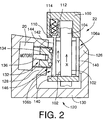
- FIG. 2 the construction of the electrically operated disc brake 22 for the front right wheel FR is shown in detail, by way of example.
- the disc brake 22 for the front left wheel FL has the same construction.
- the electrically operated disc brake 22 includes a mounting bracket 100 which is a stationary member fixed to the body of the motor vehicle, and a disc rotor 104 which has opposite friction surfaces 102 and which is rotated with the front right wheel FR.
- the mounting bracket 100 includes (a) a support portion for supporting a pair of friction members in the form of brake pads 106a, 106b on the opposite sides of the disc rotor 104 such that the brake pads 106a, 106b are movable in the axial direction of the disc rotor 104, and (b) a torque receiving portion for receiving friction forces generated between the friction surfaces 102 of the disc rotor 104 and the brake pads 106a, 106b during frictional contact therebetween.
- Character "X" in Fig. 2 represents a rotating direction of the disc rotor 104 for forward running of the motor vehicle.
- the outer brake pad 106a located on the outer side (right side as seen in Fig. 2) of the disc rotor 104 is supported by the mounting bracket 100 such that the outer brake pad 106a is substantially prevented from rotating with the disc rotor 104 during its friction contact with the outer friction surface 102, namely, substantially prevented from being "dragged” by the disc rotor 104.
- the inner brake pad 106b on the inner side (left side as seen in Fig. 2) of the disc rotor 104 is supported by the mounting bracket 100 such that the inner brake pad 106b is allowed to be “dragged” by the disc rotor 104 due to friction contact of the pad 106b with the inner friction surface 102.
- Character “Y” in Fig. 2 represents a direction of "dragging" movement of the inner brake pad 106b due to its frictional contact with the disc rotor 104.
- the dragging movement of the inner brake pad 106b is prevented when the friction force generated between the disc rotor 104 and the brake pad 106b is smaller than a predetermined threshold value, and is allowed after the friction force has exceeded the threshold value.
- the inner brake pad 106b has a rear portion 110 which engages the mounting bracket 100 through an elastic member in the form of a spring 112.
- the spring 112 does not undergo elastic deformation and prevents the dragging movement of the inner brake pad 106b with the disc rotor 104.
- the spring 112 starts elastic deformation and allows the inner brake pad 106b to be dragged with the disc rotor 104.
- the rear portion 110 of the inner brake pad 106b is associated with a stop 114 which is adapted to abut on the mounting bracket 100, for thereby limiting the distance of the dragging movement of the brake pad 106b after the friction force of the inner brake pad 106b has exceeded the threshold.
- the stop 114 prevents an excessive degree of a self-servo effect which will be described.
- the disc brake 22 further includes a caliper 120 which is movable in the axial direction of the disc rotor 104 but is not rotatable about the axis of rotation of the disc rotor 104.
- the caliper 120 is slidably supported by a plurality of pins (not shown) which are fixed to the vehicle body so as to extend in the axial direction of the rotor 104.
- the caliper 120 includes (a) a reaction portion 126 located on the outer side of the disc rotor 104, for abutting contact with the outer surface of the outer brake pad 106a, (b) a presser portion 128 located on the inner side of the disc rotor 104, for abutting contact with the inner surface of the inner brake pad 106b, and (c) a connecting portion 130 connecting the reaction and presser portions 126, 128 together.
- the presser portion 128 accommodates the electric motor 20, and carries a presser member 134 which is linked with the motor 20 through a motion converting mechanism in the form of a ballscrew mechanism 132 such that the presser member 134 and the motor 20 are coaxial with each other.
- the presser member 134 is supported by the presser portion 128 such that the presser member 134 is not rotatable about the axis of rotation of the motor 20, but is movable in the axial direction of the motor 20.
- a rotary motion of the motor 20 is converted by the ballscrew mechanism 132 into a linear motion of the presser member 134 in the axial direction of the motor 20, so that a drive force generated by the motor 20 is applied to the inner brake pad 106b, and also to the outer brake pad 106a through the caliper 120, whereby the outer and inner brake pads 106a, 106b are forced onto the opposite friction surfaces 102 of the disc rotor 104.
- the outer brake pad 106a has a backing plate 140 whose thickness is constant in the rotating direction X.
- the inner brake pad 106b has a backing plate 140 whose thickness continuously decreases in the direction Y of the dragging movement, that is, in the forward running direction of the vehicle.
- the backing plate 140 of the inner brake pad 106b has a slant back surface 142 which is remote from the inner friction surface 102 of the disc rotor 104 and which is inclined with respect to the inner friction surface 102.
- the presser member 134 is adapted to contact at its front end with the slant back surface 142 of the inner brake pad 106b.
- the presser member 134 is provided at its front end face with means for facilitating movement of the inner brake pad 106b relative to the presser member 134 while the front end face of the presser member 134 is in contact with the slant back surface 142 of the backing plate 140.
- This arrangement makes it possible to provide a wedge effect between the inner brake pad 106b and the presser member 134 during the dragging movement of the inner brake pad 106b, so that the dragging movement of the inner brake pad 106b provides a self-servo effect in the disc brake 22.
- the axis of the motor 20 (presser member 134) is perpendicular to the slant back surface 142 of the inner brake pad 106b.
- the above-indicated means for facilitating the relative movement between the inner brake pad 106b and the presser member 134 includes a plurality of balls 144 which are arranged on the front end face of the presser member 134 along a circle coaxial with the motor 20, at a substantially equal angular interval.
- the balls 144 are held on the front end face such that the balls 144 may roll in contact with the slant back surface 142.
- the balls 144 serve as a thrust bearing 146 through which the presser member 134 comes into contact with the inner brake pad 106b, so that the thrust bearing 146 reduces the friction between the front end face of the presser member 134 and the slant back surface 142 of the inner brake pad 106b.
- the balls 144 may be replaced by rollers.
- the motor 20 When the brake pedal 40 is depressed by the vehicle operator, the motor 20 is operated to advance the presser member 134 from its non-operated position, for forcing the outer and inner brake pads 106a, 106b against the respective friction surfaces 102 of the disc rotor 104, so that the front wheel FR is braked with the friction forces generated between the disc rotor 104 and the brake pads 106a, 106b.
- the friction force between the inner brake pad 106b and the disc rotor 104 is smaller than a predetermined elastic or biasing force of the spring 112, the dragging movement of the inner brake pad 106b is prevented by the spring 112, so as to prevent the self-servo effect.
- the friction force between the inner brake pad 106b and the disc rotor 104 is smaller than the elastic force of the spring 112, the front right wheel is braked by only the drive force generated by the motor 20.
- the spring 112 allows the inner brake pad 106b to be dragged with the disc rotor 104.
- the distances between the slant back surface 142 and the friction surface 102 at the points of contacts between the balls 144 and the slant back surface 142 increase, with a result of an increase in the force by which the brake pads 106a, 106b are forced onto the disc rotor 104.
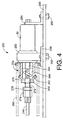
- FIG. 3 the construction of the electrically operated drum brake 32 for the rear left wheel RL is shown in detail, by way of example.
- the drum brake 32 for the rear right wheel RR has the same construction.
- the electrically operated drum brake 32 includes a stationary member in the form of a substantially circular backing plate 200 fixed to the vehicle body, and a drum 204 which has an inner circumferential friction surface 202 and which rotates with the rear right wheel RR.
- the backing plate 200 has an anchor member in the form of an anchor pin 206 fixed to a relatively radially outer portion thereof at a given circumferential position thereof.
- a connecting link in the form of an adjuster 208 of a floating type not directly fixed to the backing plate 200 At another circumferential position of the backing plate 200 which is diametrically opposite to the circumferential position at which the anchor pin 206 is fixed, there is disposed a connecting link in the form of an adjuster 208 of a floating type not directly fixed to the backing plate 200.
- a pair of friction members in the form of a pair of brake shoes 210a, 210b are disposed between and so as to connect the anchor pin 206 and the adjuster 208, such that the brake shoes 210a, 210b face the inner friction surface 202 of the drum 204.
- Each of the brake shoes 210a, 210b has an arcuate shape.
- the brake shoes 210a, 210b are fixed by respective hold-down devices 212a, 212b to the backing plate 200 such that the brake shoes 210a, 210b are movable in a plane parallel to the backing plate 200.
- the backing plate 200 has a central opening through which a rear axle shaft extends so as to be rotatable.
- Each of the brake shoes 210a, 210b is operated connected at one end thereof to the corresponding end portion of the adjuster 208, and is held at the other end in abutting engagement with the anchor pin 206, so that the shoe 210a, 210b is pivotable about the anchor pin 206.
- An adjuster spring 214 is connected to the end portions of the brake shoes 210a, 210b operatively connected to the adjuster 208, so that the end portions are biased by the adjuster spring 214 toward each other.
- a return spring 215a, 215b is connected to the other end portions of the brake shoes 210a, 210b, so that these end portions are biased by the return spring 215a, 215b toward the anchor pin 206.
- the arcuate brake shoes 210a, 210b have respective arcuate brake linings 216a, 216b held at their outer surfaces such that the brake linings 216a, 216b face the circumferential friction surface 202 of the drum 204. With friction contact of these brake linings 216a, 216b with the friction surface 202, there arise friction forces between the brake linings 216a, 216b and the drum 204.
- the adjuster 208 is provided for the purpose of changing the radial distance between the friction surface 202 and the inner arcuate surfaces of the brake shoes 210a, 210b, so as to maintain a desired radial clearance between the friction surface 202 and the surfaces of the brake linings 216a, 216b, irrespective of gradual wearing of the brake linings.
- Each brake shoe 210a, 210b consists of a rim 220 and a web 222.
- a lever 230 is pivotably connected at one end thereof to a lever support member in the form of a pin 232 fixed to the web 222 of the brake shoe 210a.
- the lever 230 and the web 222 of the other brake shoe 210b have respective cutouts which engages respective opposite ends of a strut 236 serving as a power transmitting member.
- the lever 230 and the strut 236 enable both of the brake shoes 210a, 210b of the present drum brake 32 to provide a self-servo effect during both forward and backward runs of the vehicle.
- the present drum brake 32 is a duo-servo type drum brake.
- the lever 230 is connected to the brake shoe 210a which functions as a secondary brake shoe during the forward running of the vehicle.
- the lever 230 may be connected to the brake shoe 210b which functions as a primary brake shoe during the forward running of the vehicle.
- the present electrically operated drum brake 32 is activated by pivotal movement of the lever 230 about the pin 232 at its one end when the parking brake pedal 42 is operated, as well as when the brake pedal (primary brake pedal) 40 is operated.
- a primary brake cable 240 but also a parking brake cable 242 are connected to the other end of the lever 230.
- Each of these brake cables 240, 242 consists of a strand of a plurality of wires, and is accordingly flexible.
- a compression coil spring 244 is connected at its one end to the above-indicated other end of the lever 230 and at the other end to the backing plate 200, as in the conventional hydraulically operated braking system.
- the spring 244 extends coaxially with the parking brake cable 242.
- the primary brake capable 240 is connected to a shoe expanding actuator 250 attached to the backing plate 200.
- the shoe expanding actuator 250 includes the electric motor 30 indicated above, a speed reducer 252 whose input shaft is connected to the output shaft of the motor 30, and a ballscrew mechanism 254 whose input member is connected to an output shaft of the speed reducer 252.
- the end of the primary brake cable 240 remote from the lever 230 is connected to an output member of the ballscrew mechanism 254.
- a rotary motion of the motor 30 is converted by the ballscrew mechanism 254 into a linear movement of the primary brake cable 240.
- reference numerals 256 and 258 denote brackets
- reference numerals 260 and 262 denote mounting screws for mounting the brackets 256, 258 to the backing plate 200.
- the ballscrew mechanism 254 includes an externally threaded member 264 as the input member, a nut 266 as the output member, and a plurality of balls through which the externally threaded member 264 and the nut 266 engage each other.
- the nut 266 engages a stationary housing 267 such that the nut 266 is not rotatable and is axially movable relative to the housing 267.
- a rotary motion of the externally threaded member 264 is converted into a linear or axial motion of the nut 266.
- the nut 266 has an output shaft 268 fixed to its one end remote from the externally threaded member 264, such that the output shaft 268 is coaxial with the nut 266.
- the externally threaded member 264, nut 266 and output shaft 268 are protected against exposure of their engaging portions to dust or other foreign matters, by the housing 267 and an elastic dust boot 270.
- the primary brake cable 240 is connected to the output shaft 268 through an externally threaded member 272 and a nut 274.
- the externally threaded member 272 is formed so as to extend from the end of the output shaft 268 remote from the ballscrew mechanism 254, while the nut 274 engages the externally threaded member 272 and is connected to the primary brake cable 240.
- a lock nut 276 is screwed on the externally threaded member 272 so as to lock the nut 274.
- the shoe expanding actuator 250 constructed as described above is operated in one direction to pull the primary brake cable 240 upon operation of the brake pedal 40, so that the lever 230 is pivoted about the pin 232 such that the end portion of the lever 230 to which the primary brake cable 240 is connected is moved toward the brake shoe 210b. As a result, the two brake shoes 210a, 210b are moved away from each other.
- the primary brake return spring 280 is a compression coil spring 280 which is connected at its one end to the lever 230 and at the other end to a stationary portion of the actuator 250.
- the compression coil spring 280 is disposed coaxially with the primary brake cable 240.
- the parking brake cable 242 is connected, at its end remote from the lever 230, to a parking control 284, which is mechanically operated by the parking brake pedal 42 so as to pull the parking brake cable 242 for pivoting the lever 230 in the shoe expanding direction for moving the two brake shoes 210a, 210b away from each other.
- the shoe expanding actuator 250 is operated to pull the primary brake cable 240 for pivoting the lever 230 in the above-indicated shoe expanding direction.
- the parking brake cable 242 becomes slack.
- the parking control 284 is operated to pull the parking brake cable 242 for pivoting the lever 230 also in the shoe expanding direction.
- the primary brake cable 240 becomes slack. Since the two brake cables 240, 242 which are both connected to the lever 230 and pulled at different times are flexible, the operation of one these brake cables is not influenced or disturbed by the other brake cable.
- the braking system employs a controller 50 which is principally constituted by a computer 300 incorporating a central processing unit (CPU), a read-only memory (ROM and a random-access memory (RAM).
- the controller 50 is adapted to receive various inputs, namely, output signals of various sensors and switches including an operating force sensor 302, a brake pedal operation detecting switch 304, an accelerator pedal operation detecting switch 306, a steering angle sensor 308, a vehicle deceleration sensor 310, a vehicle speed sensor, four wheel speed sensors 314 and a motor current sensor 316.
- the operation force sensor 302 generates an output signal indicative of an operation force F which acts on the brake pedal 40.
- the brake pedal operation detecting switch 304 generates an output signal indicating whether the brake pedal 40 is in operation or not.
- the accelerator pedal operation detecting switch 306 generates an output signal indicating whether the accelerator pedal 44 is in operation or not.
- the steering angle sensor 308 generates an output signal indicative of a rotation angle ⁇ of the steering wheel 46. This sensor 308 serves as a sensor for detecting whether the vehicle is turning or not.
- the vehicle deceleration sensor 310 generates an output signal indicative of a deceleration value G of the motor vehicle in the running or forward direction.
- the vehicle speed sensor 312 generates an output signal indicative of a running speed V of the motor vehicle.
- the four wheel speed sensors 314 generate respective output signals indicative of rotating speed Vw of the respective wheels FL, FR, RL, RR.
- the motor current sensor 316 is connected to coils of the motors 20, 30 of the disc and drum rakes 22, 32, and generates output signals indicative of electric currents I which are actually applied to the respective coils of the motors 20, 30 from a battery 320 through a driver 322.
- the output signals of the motor current sensor 316 are voltage signals representative of the electric current values I.
- the controller 50 provides output signals including current control signals to be applied to the above-indicated driver 322. Upon operation of the brake pedal 40, the controller 50 applies the current control signals to the driver 322 so that the electric current values I to be applied from the battery 320 through the driver 322 to the respective motors 20, 30 of the brakes 22, 32 are controlled based on the current control signals.
- the output signals provided by the controller 50 also include signals to be applied to an engine output control device and a transmission control device.
- the engine output control device includes a throttle valve control device, a fuel supply control device and an ignition timing control device, while the transmission control device includes various solenoid-operated valves.
- the engine output control device and the transmission control device are controlled according to the signals from the controller 50, so as to control the wheel drive forces to be applied to the drive wheels, for preventing excessive amounts of spinning of the drive wheels during starting or acceleration of the vehicle, that is, for effecting a so-called "traction control" of the vehicle.
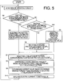
- the ROM of the computer 300 stores various programs such as those for executing a brake control routine illustrated in the flow chart of Fig. 5 and a friction coefficient estimating routine illustrated in the flow chart of Fig. 6.
- the ROM is also used for storing data tables or functional equations which represent F-T relationship patterns and I-T relationship patterns.
- Each of the F-T relationships is a relationship between the operating force F acting on the brake pedal 40 and a braking torque T applied to each wheel by operation of the corresponding brake 22, 32.
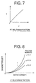
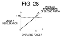
- An example of the F-T relationship patterns is indicated in the graph of Fig. 7.
- Each of the I-T relationships is a relationship between the electric current I to be applied to each motor 20, 30 and the braking torque T applied to each wheel by operation of the corresponding brake 22, 32.
- the I-T relationships are obtained by experiments or by calculation. Examples of the I-T relationship patterns are indicated in the graph of Fig. 8.
- the F-T relationship patterns and I-T relationship patterns generally differ for the front wheels FL, FR and the rear wheels RL, RR, and are therefore stored in the ROM in relation to the front wheels and the rear wheels.
- Each I-T relationship pattern indicates a change of the braking torque value T wit a change in the electric current value I.
- This I-T relationship pattern is stored for each of different friction coefficient values ⁇ of the friction members used in the brakes 22, 32. That is, the ROM stores a plurality of I-T relationship patterns corresponding to the respective different friction coefficient values ⁇ .
- the friction members consist of the brake pads 106a, 106b of the disc brakes 22 for the front wheels FL, FR, and the brake linings 216a, 216b of the drum brakes 32 for the rear wheels RL, RR.
- FIG. 9 there is schematically illustrated a relationship between the controller 50, motor 20, 30, friction member 330 and wheel 332.
- the controller 50 receives the operating force F acting on the brake pedal 40 operated by the vehicle operator. Depending upon the operating force F, the controller 50 determines the electric current I to be applied to the motor 20, 30. In response to the electric current I supplied, the motor 20, 30 generates a drive force D for forcing the friction member 330 onto the disc rotor 104 or drum 204.
- the friction member 330 having a specific friction coefficient ⁇ cooperates with the disc rotor 104 or drum 204 to apply a braking torque T to the wheel 332, based on the drive force D generated by the motor 20, 30.
- the vehicle is given a deceleration value G
- the wheel 332 is given a deceleration value Gw.
- the electric current I to be applied to the motor 20, 30 is determined on the basis of the operating force F applied to the brake pedal 40. Described more specifically, a desired braking torque T* for each wheel 332 is determined on the basis of the operating force F and according to the appropriate F-T relationship pattern. On the basis of the thus determined desired braking torque T*, the electric current I to be applied to the wheel is determined according to the I-T relationship pattern.
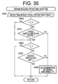
- the friction coefficient ⁇ of the friction member 330 is estimated by activating the motor 20, 30 of the brake 22, 32 under predetermined conditions, namely: when the brake pedal 40 is not in operation; when the accelerator pedal 42 is not in operation; when the vehicle is running straight, that is, is not turning; when the vehicle is not running on a bad road surface; when the vehicle is not running at a speed lower than a predetermined threshold; and when the automatic transmission 12 is not in the process of a shifting action.
- the controller 50 determines that the vehicle is running at a speed lower than the predetermined threshold, the brake 22 is not operated to estimate the friction coefficient ⁇ of the friction member 330, even when the brake pedal 40 is not in operation. That is, the estimation of the friction coefficient ⁇ is effected while the vehicle is coasting straight at a relatively high speed on a good road surface.
- the electric current I supplied to the motor 20, 30 and the vehicle deceleration value G are obtained, and the actual braking torque value T of each wheel is obtained based on the obtained vehicle deceleration value G. Further, one of the I-T relationship patterns which has a point located on or closest to a point indicative of a combination of the obtained actual braking torque value T and the obtained electric current I is selected as the presently effective I-T relationship pattern.
- the friction coefficient ⁇ corresponding to the selected or presently effective I-T relationship pattern is determined as the estimated friction coefficient ⁇ of the friction member 330, which is stored in the RAM.
- the friction coefficient ⁇ of the friction member 330 is preferably estimated for each of the four wheels, the estimation in the present embodiment is effected for each of the front and rear wheel pairs F, R, since the disc brakes 22 for the two front wheels FL, FR use the same friction members in the form of the brake pads 106a, 106b, while the drum brakes 32 for the two rear wheels RL, RR use the same friction members in the form of the brake linings 216a, 216b.
- the I-T relationship pattern corresponding to this last estimated friction coefficient ⁇ is selected to determine the electric current I on the basis of the determined desired braking torque T*. While the friction coefficient ⁇ estimated in the present vehicle run is not stored in the RAM, the I-T relationship pattern corresponding to the friction coefficient ⁇ which was estimated in the previous run of the vehicle and which is stored in the RAM is provisionally used to determine the electric current I, until the friction coefficient is estimated in the present vehicle run (until the estimation is updated).
- the I-T relationship pattern corresponding to the predetermined standard value (stored in the ROM) of the friction coefficient ⁇ is provisionally used to determine the electric current I, until the friction coefficient is estimated in the present vehicle run.
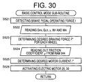
- the brake control routine of Fig. 5 is executed while an ignition switch of the vehicle is on.
- the brake control routine is initiated with step S1 in which the operating force F acting on the brake pedal 40 is detected by the operation force sensor 402.
- Step S1 is followed by step S2 to determine whether the friction coefficient value ⁇ estimated in the present run of the vehicle is stored in the RAM of the controller 50. If an affirmative decision (YES) is obtained in step S2, the control flow goes to step S3 in which the friction coefficient value ⁇ estimated in the present vehicle run and stored in the RAM is selected as the effective friction coefficient value. If a negative decision (NO) is obtained in step S2, the control flow goes to step S4 to determine whether the friction coefficient value ⁇ estimated in the previous vehicle run is stored in the RAM.
- step S4 If an affirmative decision (YES) is obtained in step S4, the control flow goes to step S5 in which the previously estimated friction coefficient value ⁇ is selected as the effective value. If a negative decision (NO) is obtained in step S4, the control flow goes to step S6 in which the predetermined standard value of the friction coefficient ⁇ is selected as the effective value.
- Step S3, S5 and S6 are followed by step S7 in which one of the stored I-T relationship patterns which corresponds to the currently selected effective friction coefficient value ⁇ is selected as the effective I-T relationship pattern.
- step S8 is implemented to determine the desired braking torque value T* for each wheel, on the basis of the detected operating force F and according to the F-T relationship pattern.
- step S9 is followed by step S9 in which a desired value I* of the electric current I for each wheel is determined on the basis of the desired braking torque value T* and according to the currently selected effective I-T relationship pattern.
- the control flow then goes to step S10 in which the electric current of the determined desired value I* is applied to the electric motor 20, 30 of each brake 22, 32.
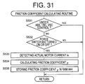
- the friction coefficient estimating routine of Fig. 6 is also executed with a predetermined cycle time while the ignition switch is on.
- the routine is initiated with step S11 to effect initialization in which an ESTIMATION flag is reset to "0".
- this flag is set at "0" it means that the friction coefficient ⁇ has not been estimated during the present run of the vehicle.
- the flag is set at "1" it means that the friction coefficient ⁇ has been estimated once during the present run of the vehicle.
- Step S11 is followed by steps S12-S18 to determine whether the predetermined conditions that should be satisfied to estimate the friction coefficient ⁇ have been satisfied. Described in detail, step S12 is implemented to determine whether the ESTIMATION flag is set at "0". If an affirmative decision (YES) is obtained in step S12, the control flow goes to step S13 to determine whether the brake pedal operation detecting switch 304 is off, that is, to determine whether the brake pedal 40 is placed at its non-operated position. If an affirmative decision (YES) is obtained in step S13, the control flow goes to step S14 to determine whether the accelerator pedal operation detecting switch 306 is off, that is, to determine whether the accelerator pedal 42 is placed at its non-operated position.
- step S12 is implemented to determine whether the ESTIMATION flag is set at "0". If an affirmative decision (YES) is obtained in step S12, the control flow goes to step S13 to determine whether the brake pedal operation detecting switch 304 is off, that is, to determine whether the brake pedal 40 is placed at its non
- step S14 If an affirmative decision (YES) is obtained in step S14, the control flow goes to step S15 to determine whether the vehicle is turning, that is, to determine whether the rotation angle ⁇ of the steering wheel 46 detected by the steering angle sensor 308 is larger than a threshold value which is close to zero. If a negative decision (NO) is obtained in step S15, the control flow goes to step S16 to determine whether the vehicle is running on a bad road surface.
- the determination in step S16 is effected by determining whether the frequency of change of the sign of the wheel deceleration value Gw is higher than a predetermined threshold value.
- the wheel deceleration value Gw is obtained by obtaining a time derivative of the wheel speed Vw detected by the wheel speed sensor 314.
- step S16 If a negative decision (NO) is obtained in step S16, the control flow goes to step S17 to determine whether the vehicle running speed V detected by the vehicle speed sensor 312 is lower than a predetermined threshold Vo. If a negative decision (NO) is obtained in step S17, the control flow goes to step S19 to determine whether the automatic transmission 12 is in the process of a shifting action. This determination in step S19 is effected based on a signal received from the automatic transmission 12. If the affirmative decision (YES) is obtained in steps S12-S14 while the negative decision (NO) is obtained in steps S15-S18, the control flow goes to step S19. In the other cases, the control flow goes back to step S12.
- step S19 a predetermined amount of electric current Io is applied to the electric motors 20 of the disc brakes 22 for the front left and right wheels FL, FR, for a predetermined time ⁇ t.
- step S19 is followed by step S20 in which the electric current I actually applied to the motors 20 is detected by the motor current sensor 316.
- step S20 is followed by step S21 in which the deceleration value G of the vehicle during activation of the disc brakes 22 is detected by the vehicle deceleration sensor 310.
- step S22 is implemented to estimate the friction coefficient ⁇ of the brake pads 106a, 106b of the disc brakes 22, on the basis of the detected electric current I and vehicle deceleration value G.
- the actual braking torque value T of the front disc brakes 22 is calculated on the basis of the detected vehicle deceleration value G.
- One of the I-T relationship patterns which has a point located on or closest to a point indicative of a combination of the detected electric current I and the calculated actual braking torque value T is selected as the effective I-T relationship pattern.
- the friction coefficient value ⁇ corresponding to the selected effective I-T relationship pattern is determined as the estimated value of the friction coefficient of the brake pads 106a, 106b.
- steps S23 through S26 similar to the above-indicated steps S19-S22 are implemented for the rear drum brakes 32, to estimate the friction coefficient value ⁇ of the brake linings 216a, 216b of the drum brakes 32.
- Step S26 is followed by step S27 in which the ESTIMATION flag is set to "1". Then, the control flow goes to step S12. However, since the ESTIMATION flag has been set to "1", the negative decision (NO) is subsequently obtained in step S12, and the estimation of the friction coefficient ⁇ of the friction members 106a, 106b, 210a, 210b is not implemented, until the present vehicle run is terminated.
- the present embodiment is adapted to effect the estimation of the friction coefficient ⁇ of the friction members only once during each run of the vehicle. Once the estimation has been effected during the present vehicle run, the friction coefficient is not updated during the present vehicle run. However, the friction coefficient may be updated during the same vehicle run.
- the graph of Fig. 10 shows a gradual drop of the vehicle speed V as a result of the activation of the disc and drum brakes 22, 32 during the estimation of the friction coefficient ⁇ of the friction members while the vehicle is coasting without the brake pedal 40 being depressed.
- the predetermined amount Io of electric current I is applied to the electric motors 20 of the front disc brakes 22, so that the vehicle speed V is reduced.
- the rate of reduction of the vehicle speed V that is, the deceleration value G of the vehicle depends upon the friction coefficient ⁇ of the brake pads 106a, 106b of the disc brakes 22. Where the friction coefficient ⁇ of the brake pads 106a, 106b is relatively high, the vehicle is decelerated with a relatively high deceleration value G1. Where the friction coefficient ⁇ is relatively low, the vehicle is decelerated with a relatively low deceleration value G2.
- the predetermined amount Io of current is applied to the electric motors 30 of the rear drum brakes 32.
- the vehicle speed V is further reduced.
- the rate of reduction of the vehicle speed V or the deceleration value G of the vehicle at this time depends upon the friction coefficient m of the brake linings 216a, 216b. Where the friction coefficient is relatively high, the vehicle is decelerated with a relatively high deceleration value G3. Where the friction coefficient is relatively low, the vehicle is decelerated with a relatively low deceleration value G4.
- portions of the controller 50 assigned to execute the brake control routine of Fig. 5 and the friction coefficient estimating routine of Fig. 6 constitute a relationship estimating and utilizing device for estimating a relationship between the electric current I to be supplied to the electric motors 20, 30 and the braking torque or force to be applied from the disc and drum brakes 22, 32 to the wheels, on the basis of the actual value of the electric current I supplied from the battery 320 to the electric motors 20, 30 and the actual values of the braking torque T of the disc and drum brakes 22, 32, which actual values are detected during operations of the brakes 22, 32 while the vehicle is running.
- the values of the braking torque to be applied to the wheels is changed with a change in the electric current to be applied to the electric motors.
- the relationship estimating and utilizing device is further adapted to utilize the estimated relationship for controlling the brakes 22, 32.
- the portion of the controller 50 assigned to execute the brake control routine of Fig. 5 constitutes relationship utilizing means for utilizing the obtained relationship
- the portion of the controller 50 assigned to implement steps S13 and S19-S26 of the friction coefficient estimating routine of Fig. 16 constitutes means for estimating the relationship while the vehicle is running without an operation of the brake pedal 40.
- the vehicle deceleration sensor 310 serves as means for detecting the vehicle deceleration G.
- the portion of the controller 50 assigned to implement steps S15 and S17 of the routine of Fig. 6 constitutes first inhibiting means for inhibiting the relationship estimating and utilizing device from operating the disc and drum brakes 22, 32 to obtain the relationship, while the vehicle is running under a condition in which the operations of the drum and disc brakes 22, 32 by the relationship estimating and utilizing device are likely to be felt unusual or uncomfortable by the vehicle operator.
- the portion of the controller 50 assigned to implement step S17 of the routine of Fig. 6 constitutes means for inhibiting the relationship estimating and utilizing device from operating the disc and drum brakes 22, 32 while the vehicle is running at a speed lower than a predetermined threshold value.
- the portion of the controller 50 assigned to implement steps S14-S16 and S18 of the routine of Fig. 6 constitutes second inhibiting means for inhibiting the relationship estimating and utilizing device from estimating and/or utilizing the relationship while the vehicle is running under a condition in which the relationship is not likely to be accurately estimated. It will also be understood that the portion of the controller 50 assigned to implement steps S14 and S18 of the routine of Fig. 6 constitutes means for inhibiting the relationship estimating and utilizing device from at least utilizing the estimated relationship while a drive force for driving the vehicle is changing. It will further be understood that the portion of the controller 50 assigned to implement step S15 of the routine of Fig. 6 constitutes means for inhibiting the relationship estimating and utilizing device from at least utilizing the estimated relationship while the vehicle is turning.
- a second embodiment of this invention is adapted to concurrently activate the disc and drum brakes 22, 32 for the four wheels while the vehicle is coasting without an operation of the brake pedal 40, and the vehicle deceleration value G is obtained during the activation of the brakes 22, 32 so that the actual braking torque values T of the brakes 22, 32 are obtained on the basis of the obtained deceleration value G.
- the second embodiment is different from the first embodiment which is adapted to activate the front disc brakes 22 and the rear drum brakes 32 at different times in steps S19 and S23, respectively.
- a friction coefficient estimating routine according to the second embodiment is illustrated in the flow chart of Fig. 11. In the following description of this routine, steps similar to those in the routine of Fig. 6 will be described only briefly.
- step S51 to effect initialization in which the ESTIMATION flag is reset to "0".
- step S11 is followed by step S52 to determine whether the ESTIMATION flag is set at "0". If an affirmative decision (YES) is obtained in step S52, the control flow goes to step S53 to determine whether the brake pedal operation detecting switch 304 is off, that is, to determine whether the brake pedal 40 is placed at its non-operated position. If a negative decision (NO) is obtained in step S53, the control flow returns to step S52. If an affirmative decision (YES) is obtained in step S53, the control flow goes to step S54 to determine whether the vehicle running speed V detected by the vehicle speed sensor 312 is lower than a predetermined threshold Vo.
- step S54 If an affirmative decision decision (YES) is obtained in step S54, the control flow returns to step S52. If a negative decision (YES) is obtained in step S54, the control flow goes to step S55 to determine whether the vehicle is running under any conditions in which the friction coefficient values ⁇ of the friction members are not likely to be accurately estimated. These conditions include: an operation of the accelerator pedal 42 to accelerate the vehicle; a turning of the vehicle; a running of the vehicle on a bad road surface; and a shifting action of the automatic transmission 12, as discussed above with respect to steps S14, S14, S16 and S18 of the routine of Fig. 6 of the first embodiment. If an affirmative decision (YES) is obtained in step S55, the control flow returns to step S52. If a negative decision (NO) is obtained in step S55, the control flow goes to step S56.
- step S56 the front disc brakes 22 for the front wheels and the rear drum brakes 32 for the rear wheels are substantially concurrently or simultaneously activated.
- step S56 is followed by step S57 in which the electric current I actually applied to each of the motors 20, 30 is detected by the motor current sensor 316.
- step S57 is followed by step S58 in which the deceleration value G of the vehicle during activation of the four brakes 22, 32 is detected by the vehicle deceleration sensor 310.
- step S59 is implemented to estimate the friction coefficient value ⁇ of the brake pads 106a, 106b of the disc brakes 22 and the friction coefficient value ⁇ of the brake linings 216a, 216b of the drum brakes 32, on the basis of the detected electric current values I and vehicle deceleration value G.
- the actual braking torque values T of the front disc brakes 22 and the actual braking torque values T of the rear drum brakes 32 are estimated on the basis of the detected vehicle deceleration value G, and depending upon a difference between the braking capacities of the disc and drum brakes 22, 32 and a difference between the load acting on the front wheels and the load acting on the rear wheels.
- a sum of the estimated braking torque values T of the front disc brakes 22 and a sum of the estimated braking torque values T of the rear drum brakes 32 are then calculated.
- a half of the former sum is determined as the actual braking torque T of each front disc brake 22, while a half of the latter sum is determined as the actual braking torque T of each rear drum brake 32.
- One of the I-T relationship patterns which has a point located on or closest to a point indicative of a combination of the detected electric current I and the calculated actual braking torque T of each front disc brake 22 is selected as the effective I-T relationship pattern.
- the friction coefficient value ⁇ corresponding to the selected effective I-T relationship pattern is obtained as the estimated value of the friction coefficient of the brake pads 106a, 106b of each front disc brake 22.
- the estimated friction coefficient value of the brake linings 216a, 216b of each rear drum brake 32 is obtained.
- the second embodiment is adapted such that the actual braking torque value T of the front disc brakes 22 and the actual braking torque value T of the rear drum brakes 32 are obtained on the basis of the same vehicle deceleration value G which is obtained during concurrent operations of the four brakes 22, 32, and the friction coefficient value ⁇ of the brake pads 106a, 106b of the front disc brakes 22 and the friction coefficient value ⁇ of the brake linings 216a, 216b of the rear drum brakes 32 are estimated independently of each other on the basis of the obtained actual front and rear braking torque values T.
- Step S59 is followed by step S60 to set the ESTIMATION flag to "1". Then, the control flow goes back to step S52.
- a third embodiment of the invention is adapted to activate the four brakes 22, 32 one after another at different times, and detect the deceleration values G for the respective brakes 22, 32 and obtain the actual braking torque values T for the respective brakes independently of each other.
- a friction coefficient estimating routine according to the third embodiment is illustrated in the flow chart of Fig. 12. In the following description of this routine, steps similar to those in the routine of Fig. 6 will be described only briefly.
- step S71 The friction coefficient estimating routine of Fig. 12 is initiated with step S71 to effect initialization in which the ESTIMATION flag is reset to "0".
- step S71 is followed by step S72 to determine whether the ESTIMATION flag is set at "0". If an affirmative decision (YES) is obtained in step S72, the control flow goes to step S73 to determine whether the brake pedal operation detecting switch 304 is off. If a negative decision (NO) is obtained in step S73, the control flow returns to step S72. If an affirmative decision (YES) is obtained in step S73, the control flow goes to step S74 to determine whether the vehicle running speed V is lower than a predetermined threshold Vo. If an affirmative decision (YES) is obtained in step S74, the control flow goes back to step S72.
- step S54 If a negative decision (NO) is obtained in step S54, the control flow goes to step S75 to determine whether the vehicle is running under any conditions in which the friction coefficient values ⁇ of the friction members are not likely to be accurately estimated. These conditions include: an operation of the accelerator pedal 42 to accelerate the vehicle; a turning of the vehicle; a running of the vehicle on a bad road surface; and a shifting action of the automatic transmission 12, as discussed above with respect to steps S14, S14, S16 and S18 of the routine of Fig. 6 of the first embodiment. If an affirmative decision (YES) is obtained in step S75, the control flow returns to step S72. If a negative decision (NO) is obtained in step S75, the control flow goes to step S76.
- step S76 the two front disc brakes 22 and the two rear drum brakes 32 are sequentially activated one after another, for instance, in the order of the disc brake 22 for the front left wheel FL, the disc brake 22 for the front right wheel FR, the drum brake 32 for the rear left wheel RL, and the drum brake 32 for the rear right wheel RR.
- step S76 is followed by step S77 in which the values of the electric current I actually supplied to the motors 20, 30 are detected during sequential activations of the four brakes 22, 32.
- step S77 is followed by step S78 in which the deceleration values G are detected during the sequential activations of the four brakes 22, 32. It is noted that while steps S76-S78 are sequentially and repeatedly implemented for each of the four brakes 22, 32, although the flow chart of Fig. 12 does not explicitly show this arrangement.
- the thus detected vehicle acceleration values G accurately reflect the actual braking torque values T of the respective brakes 22, 32.
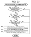
- step S79 is implemented to estimate the friction coefficient values ⁇ of the brake pads 106a, 106b of the disc brakes 22 and the friction coefficient values ⁇ of the brake linings 216a, 216b of the drum brakes 32, on the basis of the detected electric current values I and vehicle deceleration values G. Described in detail, the actual braking torque value T of each brake 22, 32 is estimated on the basis of the corresponding vehicle deceleration value G. Then, One of the I-T relationship patterns which has a point located on or closest to a point indicative of a combination of the detected electric current I and the calculated actual braking torque T of each brake 22, 32 is selected as the effective I-T relationship pattern.
- step S79 is followed by step S80 to set the ESTIMATION flag to "1". Then, the control flow returns to step S72.
- a fourth embodiment of this invention is adapted to inhibit the detection of the vehicle deceleration G to obtain the actual braking torque T where the gradient of the road surface on which the vehicle is running is higher than a predetermined threshold.
- the vehicle deceleration G is detected irrespective of the gradient of the road surface.
- FIG. 13 there is shown an arrangement of an electrically operated braking system according to the fourth embodiment, which includes a road gradient sensor 340 for detecting the gradient of the road surface.
- a friction coefficient estimating routine executed according to a program stored in a ROM of a computer 344 of a controller 342 of the braking system of the present fourth embodiment is illustrated in the flow chart of Fig. 14.
- steps similar to those in the first embodiment will be described only briefly.
- step S81 The friction coefficient estimating routine of Fig. 14 is initiated with step S81 to effect initialization in which the ESTIMATION flag is reset to "0".
- step S81 is followed by step S82 to determine whether the ESTIMATION flag is set at "0". If an affirmative decision (YES) is obtained in step S82, the control flow goes to step S83 to determine whether the brake pedal operation detecting switch 304 is off. If a negative decision (NO) is obtained in step S83, the control flow returns to step S72. If an affirmative decision (YES) is obtained in step S83, the control flow goes to step S84 to determine whether the vehicle running speed V is lower than a predetermined threshold Vo. If an affirmative decision (YES) is obtained in step S84, the control flow goes back to step S82.
- step S84 If a negative decision (NO) is obtained in step S84, the control flow goes to step S85 to determine whether the vehicle is running under any conditions in which the friction coefficient values ⁇ of the friction members are not likely to be accurately estimated. These conditions include: an operation of the accelerator pedal 42 to accelerate the vehicle; a turning of the vehicle; a running of the vehicle on a bad road surface; and a shifting action of the automatic transmission 12, as discussed above with respect to steps S14, S14, S16 and S18 of the routine of Fig. 6 of the first embodiment.
- the conditions that inhibit the estimation of the friction coefficient ⁇ also include a condition that the gradient of the road surface on which the vehicle is running is higher than the predetermined threshold value. If an affirmative decision (YES) is obtained in step S85, the control flow returns to step S82. If a negative decision (NO) is obtained in step S85, the control flow goes to step S86.
- step S86 the disc and drum brakes 22, 32 are activated in one of the following modes: (a) The four brakes 22, 32 are substantially concurrently activated, as in the second embodiment of Fig. 11; (b) the front disc brakes 22 are concurrently activated, and the rear drum brakes 32 are concurrently activated, but after or before the activation of the disc brakes 22, as in the first embodiment of Fig. 6; and (c) the four brakes 22, 32 are sequentially activated, as in the third embodiment of Fig. 12.
- Step S86 is followed by step S87 in which the electric current I supplied to each brake 22, 32 is detected.
- step S87 is followed by step S88 in which the deceleration value or values G is/are detected during the activation of the four brakes 22, 32.
- step S89 is implemented to estimate the friction coefficient values ⁇ of the friction members of the brakes 22, 32, on the basis of the detected electric current values I and vehicle deceleration value or values G, in one of the manners described with steps S26, S59 and S79.
- step S89 is followed by step S90 to set the ESTIMATION flag to "1". Then, the control flow returns to step S82.
- a fifth embodiment of this invention is adapted to obtain the actual braking torque values T on the basis of deceleration values Gw of the wheels.
- the actual braking torque T is obtained on the basis of the detected vehicle deceleration G.
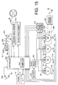
- FIG. 15 there is shown an arrangement of an electrically operated braking system according to the fourth embodiment, which does not include the vehicle deceleration sensor 310, since the vehicle deceleration G is not used to obtain the actual braking torque T in the present fifth embodiment.
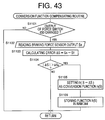
- a friction coefficient estimating routine executed according to a program stored in a ROM of a computer 362 of a controller 360 of the braking system of the present fifth embodiment is illustrated in the flow chart of Fig. 16.
- steps similar to those in the first embodiment will be described only briefly.
- step S101 to effect initialization in which the ESTIMATION flag is reset to "0".
- step S102 to determine whether the ESTIMATION flag is set at "0". If an affirmative decision (YES) is obtained in step S102, the control flow goes to step S103 to determine whether the brake pedal operation detecting switch 304 is off. If a negative decision (NO) is obtained in step S103, the control flow returns to step S102. If an affirmative decision (YES) is obtained in step S103, the control flow goes to step S104 to determine whether the vehicle running speed V is lower than a predetermined threshold Vo. If an affirmative decision (YES) is obtained in step S104, the control flow goes back to step S102.
- step S104 If a negative decision (NO) is obtained in step S104, the control flow goes to step S105 to determine whether the vehicle is running under any conditions in which the friction coefficient values ⁇ of the friction members are not likely to be accurately estimated. These conditions include: an operation of the accelerator pedal 42 to accelerate the vehicle; a turning of the vehicle; a running of the vehicle on a bad road surface; and a shifting action of the automatic transmission 12, as discussed above with respect to steps S14, S14, S16 and S18 of the routine of Fig. 6 of the first embodiment. If an affirmative decision (YES) is obtained in step S105, the control flow returns to step S102. If a negative decision (NO) is obtained in step S105, the control flow goes to step S106.
- step S106 the front disc brakes 22 for the front wheels and the rear drum brakes 32 for the rear wheels are substantially concurrently or simultaneously activated.
- step S106 is followed by step S107 in which the electric current I actually applied to each of the motors 20, 30 is detected by the motor current sensor 316.
- step S107 is followed by step S108 in which the deceleration value Gw of each of the four wheels FL, FR, RL, RR is calculated.
- the deceleration value Gw of each wheel is calculated by obtaining a time derivative of the rotating speed Vw of that wheel detected by the wheel speed sensor 314.
- the graph of Fig. 17 shows a change in the wheel speed Vw during activation of the brakes 22, 32.
- the friction coefficient ⁇ of the friction members of the brake 22, 32 is relatively high, the rate of reduction of the wheel speed Vw, that is, the deceleration value Gw of the wheel is relatively high.
- the friction coefficient is relatively low, the wheel deceleration value Gw is relatively low.
- step S109 is implemented to estimate the friction coefficient values ⁇ of the friction members of the four brakes 22, 32, on the basis of the detected electric current values I and calculated wheel deceleration values Gw. Described in detail, the actual braking torque values T of the brakes 22, are estimated on the basis of the calculated wheel deceleration values Gw.
- One of the I-T relationship patterns which has a point located on or closest to a point indicative of a combination of the detected electric current I and the calculated actual braking torque T of each brake 22, 32 is selected as the effective I-T relationship pattern.
- the friction coefficient value ⁇ corresponding to the selected effective I-T relationship pattern is obtained as the estimated value of the friction coefficient of each brake 22, 32.
- step S110 is implemented to set the ESTIMATION flag to "1". The control flow then goes back to step S102.
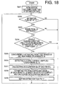
- a sixth embodiment of the invention is different from the fifth embodiment, only in the friction coefficient estimating routine illustrated in the flow chart of Fig. 18.
- step S201 the friction coefficient ⁇ of the friction members of the brakes 22, 32 is effected while the brake pedal 40 is operated.
- the routine is initiated with step S201 to effect initialization in which the ESTIMATION flag is reset to "0".
- step S201 is followed by step S202 to determine whether the ESTIMATION flag is set at "0". If an affirmative decision (YES) is obtained in step S202, the control flow goes to step S203 to determine whether the brake pedal operation detecting switch 304 is on, that is whether the brake pedal 40 is in operation. If a negative decision (NO) is obtained in step S203, the control flow returns to step S202.
- step S203 If an affirmative decision (YES) is obtained in step S203, the control flow goes to step S204 to determine whether the whether the vehicle is running under any conditions in which the friction coefficient values ⁇ of the friction members are not likely to be accurately estimated.
- These conditions include: an operation of the accelerator pedal 42 to accelerate the vehicle; a turning of the vehicle; a running of the vehicle on a bad road surface; and a shifting action of the automatic transmission 12, as in the fifth embodiment.
- the conditions that inhibits the estimation of the friction coefficient ⁇ include an operation of the braking system in an anti-lock fashion, and stopping of the vehicle.
- the anti-lock control of the disc and drum brakes 22, 32 is effected with the electric motors 20, 30 being controlled by the controller 50 on the basis of the output signals of the wheel speed sensors 314.
- step S204 The stopping of the vehicle is detected if the vehicle running speed V detected by the vehicle speed sensor 312 is lower than a predetermined lower limit. If an affirmative decision (YES) is obtained in step S204, the control flow returns to step S202. If a negative decision (NO) is obtained in step S205, the control flow goes to steps S205-S209, which are similar to steps S106-S110 of the routine of Fig. 16 in the fifth embodiment.
- a seventh embodiment of the present invention is different from the first embodiment, in that the actual braking torque values T of the brakes 22, 32 are detected by sensors exclusively provided for this purpose.
- FIG. 19 The arrangement of an electrically operated braking system according to the seventh embodiment is schematically shown in Fig. 19.
- This braking system includes (a) a first force sensor 380 provided in each front disc brake 22, to detect the actual braking torque T, and (b) a second force sensor 382 provided in each rear drum brake 32, to detect the actual braking torque T.
- the present braking system does not include the vehicle deceleration sensor 310.
- FIG. 20 there is shown the electrically operated disc brake 22 for each front wheel, wherein the first force sensor 380 is interposed between the spring 112 and the mounting bracket 100.
- FIG. 21 there is shown the electrically operated drum brake 32 for each rear wheel, wherein the second force sensor 382 is disposed on one of the brake shoes 210a, 210b, that is, the secondary shoe 210a which will receive a larger load than the primary shoe 210b.
- the second force sensor 382 may be disposed on the anchor pin 206.
- a friction coefficient estimating routine executed according to a program stored in a ROM of a computer 386 of a controller 384 of the present braking system is illustrated in the flow chart of Fig. 22.
- steps similar to those in the first embodiment will be described only briefly.
- step S301 The routine of Fig. 22 is initiated with step S301 to effect initialization in which an ESTIMATION flag is reset to "0".
- step S301 is followed by step S302 to determine whether the whether the ESTIMATION flag is set at "0". If an affirmative decision (YES) is obtained in step S202, the control flow goes to step S303 to determine whether the brake pedal operation detecting switch 304 is off. If a negative decision (NO) is obtained in step S303, the control flow goes back to step S302. If an affirmative decision (YES) is obtained in step S303, the control flow goes to step S304 to determine whether the vehicle speed V is lower than a predetermined threshold Vo. If an affirmative decision (YES) is obtained in step S304, the control flow goes back to step S302.
- step S304 If a negative decision (NO) is obtained in step S304, the control flow goes to step S305 to determine whether the vehicle is running under any conditions in which the friction coefficient ⁇ is not likely to be accurately estimated. These running conditions include: an operation of the accelerator pedal 42; a turning of the vehicle; a running of the vehicle on a bad road surface; and a shifting action of the automatic transmission 12, as described above with respect to the first embodiment. If an affirmative decision (YES) is obtained in step S305, the control flow goes back to step S302. If a negative decision (NO) is obtained in step S305, the control flow goes to step S306.
- step S306 the disc and drum brakes 22, 32 are activated in one of the following modes: (a) The four brakes 22, 32 are substantially concurrently activated, as in the second embodiment of Fig. 11; (b) the front disc brakes 22 are concurrently activated, and the rear drum brakes 32 are concurrently activated, but after or before the activation of the disc brakes 22, as in the first embodiment of Fig. 6; and (c) the four brakes 22, 32 are sequentially activated, as in the third embodiment of Fig. 12.
- Step S306 is followed by step S307 in which the electric current I supplied to each brake 22, 32 is detected.
- Step S307 is followed by step S308 in which the actual braking torque values T of the disc and drum brakes 22, 32 are detected by the first and second force sensors 380, 382, respectively, during the activation of the brakes 22, 32.
- step S309 is implemented to estimate the friction coefficient values ⁇ of the friction members of the brakes 22, 32, on the basis of the detected electric current values I and actual braking torque values T.
- One of the I-T relationship patterns which has a point located on or closest to a point indicative of a combination of the electric current I and the braking torque value T of each brake 22, 32 is selected as the effective I-T relationship pattern.
- the friction coefficient ⁇ corresponding to the selected I-T relationship pattern is obtained as the estimated friction coefficient value for each brake.
- the control flow then goes to step S309 to the ESTIMATION flag to "1". Then, the control flow returns to step S310.
- the embodiments which have been described are adapted to detect various physical parameters such as the electric current I supplied to each electric motor 20, 30, vehicle deceleration G, wheel deceleration Gw and actual braking torque T of the brakes 22, 32. Each of these physical parameters is detected for a predetermined time period.
- the peak value or an average of a plurality of values obtained in the detection period may be used as the detected value. Alternatively, an integral value of the values obtained in the detection period may be used as the detected value.
- Fig. 23 shows an electrically operated braking system constructed according to an eighth embodiment of the invention, which includes electrically operated front disc brakes 522 each having the electric motor 20 described above, and electrically operated rear drum brakes 532 each having the electric motor 30 also described above. These disc and drum brakes 530, 532 do not use a hydraulic working fluid.
- the braking system of Fig. 23 includes the engine 10, automatic transmission 12, parking brake pedal 43, accelerator pedal 44 and steering wheel 46.
- the braking system of Fig. 23 further includes mechanically operated rear drum brakes 536 which are operated as emergency brakes, by a force produced as a result of an operation of a brake operating member in the form of a brake pedal 534.
- This drum brake 536 does not use a hydraulic working fluid, either.
- each of the rear left and right wheels RL, RR is provided with both the electrically operated drum brake 532 and the mechanically operated drum brake 536.
- These drum brakes 532, 536 commonly use the same drum 204 and the same brake shoes 210a, 210b (brake linings 216a, 216b).
- the vehicle Upon operation of the brake pedal 534, the vehicle is braked by at least one of the three pairs of brakes 522, 532, 536. That is, there are the following four cases:
- parking brake is applied to the front left and right wheels FL, FR by the disc brakes 522 upon operation of the parking brake pedal 42.
- the parking brake is applied by holding the electric motors 20 (ultrasonic motors) of the disc brakes 522 stationary with a holding torque while the parking brake pedal 42 is kept operated.
- the disc brake 522 for the front right wheel FR is shown in detail in Fig. 24.
- the disc brake 533 for the front left wheel FL has the same construction as shown in Fig. 24.
- the disc brake 522 of Fig. 24 is identical with the disc brake 22 of Fig. 2 of the first embodiment, except for the configuration of brake pads 606 (more specifically, inner brake pad 606b) and the provision of a force switch 650 provided in a stationary member in the form of the mounting bracket 100.
- the inner brake pad 606b of the disc brake 522 has a backing plate 640 which has a constant thickness.
- the pads 606a, 606b are "dragged" or rotated with the disc rotor 102 in the direction X.
- the amounts of rotation of the pads 606a, 606b are limited by respective torque receiving portions 610a, 610b of the mounting bracket 100. Namely, the amount of rotation of the outer pad 606a is limited by abutting contact of its end face with the outer torque receiving portion 610a, while the amount of rotation of the inner pad 606b is limited by abutting contact of the force switch 650 with the inner torque receiving portion 610b, as described below by reference to Fig. 25.
- the torque receiving portions 610a, 610b function as support members for supporting the friction members so as to prevent rotation of the friction members in the form of the brake pads 606a, 606b with the rotor 104 when the friction members are held in frictional contact with the rotor 104.
- the presser portion 134 moved by the electric motor 20 through the ballscrew mechanism 136 is not provided at its front end with such a thrust bearing as provided in the disc brake 22 of Fig. 22.
- the presser portion 134 cooperates with the ballscrew mechanism 132 to constitute a pressing device for forcing the brake pads 606a, 606b onto the rotor 104.
- the force switch 650 is provided in the inner torque receiving portion 610b which is adapted to receive a torque from the inner brake pad 606b.
- the force switch 650 consists of a movable member 652 and an elastic member in the form of a coned disc spring 654.
- the movable member 652 is a stepped cylindrical member including a large-diameter portion 656 and a small-diameter portion 658 which both have a circular cross sectional shape and are coaxial with each other.
- the large-diameter portion 656 is received axially movably within the inner torque receiving portion 610b, while the small-diameter portion 658 extends through a center opening of the coned disc spring 654.
- the coned disc spring 654 biases the movable member 652 toward the inner brake pad 606b. Normally, the movable member 652 is held in abutting contact with a stop portion 659 formed with the mounting bracket 100. In other words, the stop portion 659 determines the fully retracted position of the movable member 652.
- the inner brake pad 606b is rotated with the disc rotor 104 in the direction Y as indicated in Fig. 25
- the movable member 652 is moved away from the fully retracted position against the biasing force of the spring 654.
- the small-diameter portion 658 has a movable contact 660 fixed to its end face.
- the inner torque receiving portion 610b has a stationary contact 662 which is an elastic member.
- the movable contact 660 comes into contact with the stationary contact 662 when the movable member 652 is moved to its fully advanced position by the inner brake pad 606b against the biasing action of the coned disc spring 654.
- the fully advanced position of the movable member 652 is determined by abutting contact of the end face of the small-diameter portion 658 with the surface of the inner torque receiving portion 610b. In this arrangement, a force generated by friction contact of the inner brake pad 610b with the rotor 104 is transmitted to the inner torque receiving portion 610b through the movable member 652.
- the stationary contact 662 is electrically connected through a wire 664 to the electronic control unit 550.
- the wire 664 extends through the mounting bracket 100.
- the stationary contact 662 and the wire 664 are electrically insulated from the mounting bracket 100 by an insulator 665.
- the movable contact 660 is grounded through the electrically conductive movable member 652 and mounting bracket 100 and through a wire 666 connected to the mounting bracket 100.
- the movable contact 660 is normally held away from the stationary contact 662 with the movable member 652 held in its fully retracted position under the biasing force of the coned disc spring 654.
- the force switch 650 is normally held in its off state.
- a predetermined value a pre-load given to the coned disc spring 654
- the movable member 652 starts moving with the inner brake pad 606b against the biasing force of the spring 654, from the fully retracted position toward the fully advanced position in which the movable contact 660 contacts the stationary contact 662, whereby the force switch 650 is turned on.
- the force switch 650 may be provided in the outer torque receiving portion 610a of the mounting bracket 100.
- FIG. 26 there is shown the electrically operated drum brake 532 for the rear right wheel RR.
- the drum brake 532 for the rear left wheel RL has the same construction as shown in Fig. 26.
- the drum brake 532 is identical with the drum brake 32 of Fig. 3 of the first embodiment, except for a strut 736 provided in place of the strut 236.
- This strut 736 incorporates a length adjusting mechanism including a screw device, which is manipulated to adjust a clearance or gap between the brake shoes 210a, 10b and the drum 204.
- This drum brake 536 uses an emergency brake cable 782 and a return spring 784, which are similar to the parking brake cable 242 and the return spring 244 provided in the drum brake 32 of Fig. 3.
- the emergency brake cable 782 is connected at one end thereof to the end of the lever 230 to which the primary brake cable 240 of the electrically operated drum brake 532 is connected.
- the lever 230 is pivoted to force the brake linings 216a, 216b onto the drum 204, for thereby braking the rear right wheel RR.
- the emergency brake cable 782 is guided through an outer tubing 786, as indicated in Fig. 23.
- the emergency brake cable 782 connected at its one end to the mechanically operated drum brake 536 for each rear wheel is operatively connected at the other end to the brake pedal 534 through a manual brake control device 800, as shown in Fig. 23.
- the manual brake control device 800 is shown in enlargement in Fig. 27, together with a brake pedal device 802.
- the brake pedal device 802 includes a pedal bracket 804 fixed to the vehicle body.
- the brake pedal 534 is supported at a proximal end thereof by the pedal bracket 804 such that the brake pedal 534 is pivotable at its proximal end about an axis which extends in the lateral or transverse direction of the vehicle.
- the brake pedal 534 is held in its non-operated position, which is determined by abutting contact of the brake pedal 534 with a stop 806 under a biasing action of a return spring 808.
- the brake pedal 834 is pivotally connected to the rear end of a push rod 312 through a clevis 810, which serves as a pivotal link mechanism.
- the push rod 312 is movable in the longitudinal or running direction of the vehicle.
- a pivotal motion of the brake pedal 534 is converted into a linear motion of the push rod 312.
- the manual brake control device 800 includes a housing 814 fixed to the vehicle body. Within a bore formed in the housing 814, there are slidably received a first piston 816 and a second piston 818 which are disposed coaxially with each other such that the pistons 816, 818 are movable relative to each other in the longitudinal direction of the vehicle.
- the push rod 812 engages at its front end with the rear end of the first piston 816.
- An operating force f acting on the brake pedal 534 is transmitted in the forward direction to the first piston 816 through the push rod 812.
- the brake pedal 534 is mechanically connected to the first piston 816.
- the manual brake control device 800 gives the vehicle operator an operating feel of the brake pedal 534 as obtained with a brake pedal in a hydraulically operated braking system.
- the first piston 816 and the spring 320 cooperate to constitute a pedal stroke simulator generally indicated at 812 in Fig. 27.
- the first piston 816 has an engaging portion in the form of a projection 822 which extends toward the second piston 818 such that the projection 822 is coaxial with the pistons 816, 818.
- the second piston 818 has a fully retracted position determined by a stop 824.
- the retracted position of the second piston 818 or the position of the stop 824, which determines an initial distance between the two pistons 816, 818, is determined so that the projection 822 is spaced apart from the second piston 818 when the brake pedal 534 is placed in its non-operated position of Fig. 27, but is brought into abutting contact with the second piston 818 when the operating force f acting on the brake pedal 534 has reached a reference value f 0 .
- This reference value f 0 is determined such that the operating force f equal to the reference value f 0 produces a relatively high deceleration value G (e.g., 1.2G) of the vehicle which is not usually obtained when the electrically operated disc and drum brakes 522, 532 are both normal. If and after the operating force f exceeds the thus determined reference value f 0 when the disc and drum brakes 522, 532 are both normal, the second piston 818 is moved forward from the fully retracted position, and the mechanically operated drum brake 536 is also activated simultaneously, the rate of increase of the vehicle deceleration value G with an increase in the operating force f is raised, as indicated in the graph of Fig. 28.
- G e.g., 1.2G
- the second piston 818 is connected through a lever device 826 to the rear end of the emergency brake cable 782 of the mechanically operated drum brake 536 for each rear wheel, as shown in Fig. 27.
- the lever device 826 includes a lever 828 and a lever bracket 830 fixed to the vehicle body.
- the lever 828 is supported at a proximal end thereof by the lever bracket 830 such that the lever 828 is pivotable about the proximal end in a plane which includes the axis of the second piston 818.
- the lever 828 is connected at an intermediate portion thereof to the front end of the second piston 818 through a clevis 832, and is held in its fully retracted position under a biasing action of a return spring 834 such that the clevis 832 is held in abutting contact with the front end of the second piston 818.
- the lever 828 is connected at a free end thereof to the end of the emergency brake cable 782 of each drum brake 536 through a clevis 836.
- a forward movement of the second piston 818 in the left direction as seen in Fig. 27
- the lever 828 will be, pivoted in the clockwise direction (as seen in Fig. 27), pulling the emergency brake cable 782 in the left direction as seen in Fig. 27, out of the outer tubing 786, whereby the movement of the second piston 818 is boosted into the movement of the emergency brake cable 782.
- Reference numeral 838 in Fig. 27 denotes a bracket fixed to the vehicle body for fixing the outer tubing 786 for the emergency brake cable 782.
- the electric motors 30 of the actuators 250 are operated to pull the primary brake cables 240 to force the brake shoes 210a, 210b onto the drum 204.
- the flexible emergency brake cables 782 are contracted, so that the actions of the brake shoes 210a, 210b by operation of the electrically operated drum brakes 532 are not disturbed by the manual brake control device 800.
- the primary brake cables 240 and the emergency brake cables 782 which are both flexible and connected to the same lever 230 are not disturbed by the emergency brake cables 782 and the primary brake cables 240, respectively, when the electrically and mechanically operated drum brakes 532, 536 are operated at different times.
- the control system includes the electronic control unit (ECU) 350, which is principally constituted by a computer 836 incorporating a read-only memory (ROM) 842 and a random-access memory (RAM) 844.
- ECU electronice control unit
- ROM read-only memory
- RAM random-access memory
- various sensors and switches including: the above-indicated force switches 650 of the disc brakes 522 for the front left and right wheels FL, FR; a brake pedal switch 850; an operation force sensor 848; a parking pedal switch 851; an accelerator pedal switch 852; an accelerator operation amount sensor 853; a steering angle sensor 854; a yaw rate sensor 855; a longitudinal acceleration sensor 856; a lateral acceleration sensor 857; a front wheel load sensor 858; a rear wheel load sensor 859; four wheel speed sensors 860; four motor position sensors 862 and four motor current sensors 864.
- the operation force sensor 848 generates an output signal indicative of the operating force f acting on the brake pedal 534.
- the brake pedal switch 850 which is a primary brake operation sensor, generates an output signal indicative of whether the brake pedal 34 is in operation. That is, the brake pedal switch 850 is placed in an off state when the brake pedal 534 is not in operation, and in an on state when the brake pedal 534 is in operation.
- the parking pedal switch 851, which is a parking brake operation sensor, generates an output signal indicative of whether the parking brake pedal 42 is in operation. That is, the parking brake pedal switch 851 is placed in an off state when the parking brake pedal 42 is not in operation, and in an on state when the parking brake pedal 42 is in operation.
- the accelerator pedal switch 852 which is an accelerator operation sensor, generates an output signal indicative of whether the accelerator pedal 44 is in operation. That is, the accelerator pedal switch 852 is placed in an off state when the accelerator pedal 44 is not in operation, and in an on state when the accelerator pedal 44 is in operation.
- the accelerator pedal operation amount sensor 853 generates an output signal indicative of an operating amount of the accelerator pedal 44.
- the steering angle sensor 354, which is a sensor for detecting an angle of turn of the vehicle, generates an output signal indicative of the angle of rotation of the steering wheel 46.
- the yaw rate sensor 855 generates an output signal indicative of a yaw rate ⁇ of the vehicle.
- the longitudinal acceleration sensor 856 generates an output signal indicative of a deceleration value G FR of the vehicle in the longitudinal direction of the vehicle.
- the lateral acceleration sensor 857 generates an output signal indicative of a lateral acceleration value G LR of the vehicle in the lateral direction of the vehicle.
- the front wheel load sensor 858 generates an output signal indicative of a load W F acting on the front axle in the vertical direction
- the rear wheel load sensor 859 generates an output signal indicative of a load W R acting on the rear axle in the vertical direction.
- Each of the four wheel speed sensors 860 generates an output signal indicative of the rotating speed Vw of the corresponding wheel.
- Each of the motor position sensors 860 generates an output signal indicative of the angular position of the corresponding electric motor 20, 30.
- Each of the motor current sensors 864 generates an output signal indicative of an electric current supplied to the coil of the corresponding motor 20, 30.
- the ECU 550 is also connected to a first driver 866 and a second driver 868.
- the first driver 866 is connected between an electric power source in the form of a first battery 870 and the electric motor 20 of each electrically operated disc brake 522.
- the second driver 868 is connected between an electric power source in the form of a second battery 872 and the electric motor 30 of each electrically operated drum brake 532.
- the ECU 550 applies control commands to the first and second drivers 866, 868, so that the amounts of the electric current to be supplied from the first and second batteries 870, 872 to the respective electric motors 20, 30 are controlled according to the control commands, which are determined by the operating force f acting on the brake pedal 534.
- the braking system also includes a primary battery 874 independent of the first and second batteries 870, 872.
- This primary battery 874 is used for operating all electrical components of the vehicle, except the electric motors 20, 30 of the brakes 522, 532.
- the ECU 550 is powered by the primary battery 874, rather than the first and second batteries 870, 872.
- the ECU 550 is further connected to an engine output control device (throttle control unit, a fuel supply control unit, ignition timing control unit, etc.) for controlling the engine 10, and a shift control device (solenoid-operated valves, etc.) for controlling the automatic transmission 12.
- the ECU 550 applies control commands to these engine output control device and shift control device to effect a traction control of the vehicle, namely, to control the running vehicle so as to avoid excessive spinning or slipping of the drive wheels.
- the ECU 550 is also connected to a brake failure indicator light 876 which is turned on in the event of an electrical or other failure or defect of the electrically operated disc and drum brakes 522, 532.
- the ROM 842 of the computer 846 stores various control programs including programs for executing various routines such as a brake control routine and a friction coefficient calculating routine.
- the brake control routine is formulated to control the brakes 522, 532 in various modes such as a basic control mode, an anti-lock control mode, a traction control mode and vehicle stability control (VSC) mode.
- the basic control mode the electric motors 20, 30 of the disc and drum brakes 522, 532 are controlled so as to achieve the vehicle deceleration corresponding to the operating force f acting on the brake pedal 534, on the basis of the output signals of the operation force sensor 848, brake pedal switch 850, front and rear wheel load sensors 858, 859, motor position sensors 862 and motor current sensors 864, while monitoring the detected angular positions of the motors 20, 30 and the detected amounts of electric current supplied to the motors 20, 30, such that the braking force is suitably distributed to the front wheels FL, FR and the rear wheels RL, RR.
- VSC vehicle stability control
- the electric motors 20, 30 are controlled to control the braking torque values of the wheels, so as to avoid an excessive locking tendency of each wheel, on the basis of the output signals of the brake pedal switch 850, wheel speed sensors 860, motor position sensors 862 and motor current sensors 864.
- the electric motors 20, 30 are controlled to control the driving torque values of the drive wheels, so as to avoid an excessive spinning or slipping tendency of each drive wheel, on the basis of the output signals of the accelerator pedal switch 852, accelerator operation amount sensor 853, wheel speed sensors 860, motor position sensors 862 and motor current sensors 864.
- the electric motors 20, 30 are controlled to control a yaw movement of the vehicle, by controlling a difference between the braking forces of the left and right wheels, so as to avoid an excessive drift-out or spinning tendency of the vehicle, on the basis of the steering angle sensor 854, yaw rate sensor 855, lateral acceleration sensor 858, wheel speed sensors 860, motor position sensors 862 and motor current sensors 864.
- the brake control routine is illustrated in the flow chart of Fig. 29. This routine is repeatedly executed while the ignition switch of the vehicle is held on. The routine is initiated with step S501 to determine whether the brake pedal 534 is in operation, that is, whether the brake pedal switch 530 is in the on state. If an affirmative decision (YES) is obtained, the control flow goes to step S2, in which the braking system is controlled in the basic control mode according to a basic control mode sub-routine illustrated in the flow chart of Fig. 30, which will be described.
- step S521 in which the operating force f acting on the brake pedal 534 is detected on the basis of the output signal of the operation force sensor 848.
- step S522 is implemented to read the longitudinal acceleration value G FR , lateral acceleration value G LR , front wheel load W F , rear wheel load W R and yaw rate ⁇ , which are represented by the output signals of the appropriate sensors.
- step S523 a desired braking torque or force F* for each wheel is determined on the basis of the detected values G FR , F LR , W F , W R , ⁇ , so as to achieve an optimum or ideal front-rear distribution of the braking force depending upon the vehicle weight and deceleration values G, and so as to avoid yawing and/or lateral slipping tendency of the vehicle due to a large difference between the braking force of the left wheels and the braking force of the right wheels.
- Step S523 is followed by step S524 to read the friction coefficient ⁇ of the inner brake pad 606b of each front disc brake 522, which is stored in the RAM 844.
- the standard value of the friction coefficient ⁇ is stored in the RAM 844, and is provisionally used before the friction coefficient ⁇ is calculated according to a friction coefficient calculating routine (which will be described) and stored in the RAM 844.
- a friction coefficient calculating routine which will be described
- the friction coefficient value ⁇ stored in the RAM 844 is updated.
- step S525 determines a desired value I* of the electric current I to be supplied to the motor 20, 30 of each brake 522, 532.
- the desired electric current value I* for the motor 30 of each rear drum brake 532 is determined on the basis of the determined desired braking force F* and according to a predetermined relationship between the desired braking force F* and the desired electric current I*. This relationship is stored in the ROM 842.
- the desired electric current value I* for the motor 30 of each front disc brake 522 is determined according to the following equation, based on a fact that the desired electric current I* corresponds to a force N by which the brake pads 606a, 606b are forced onto the disc rotor 104.
- I* F*/( ⁇ K)
- K represents a constant
- step S526 in which each motor 20, 30 is activated with the determined desired electric current I* supplied thereto.
- step S502 of the brake control routine of Fig. 29 one cycle of execution of the basic control mode sub-routine of Fig. 30 is terminated in step S502 of the brake control routine of Fig. 29.
- Step S502 of the routine of Fig. 29 is followed by step S503 to determine whether it is necessary to control the brakes 522, 532 in the anti-lock control mode, that is, whether the vehicle wheels have an excessive locking tendency. If a negative decision (NO) is obtained in step S503, one cycle of execution of the routine of Fig. 29 is terminated. If an affirmative decision (YES) is obtained in step S503, the control flow goes to step S504 in which the braking system is controlled in the anti-lock control mode. Step S504 is followed by step S505 to determine whether the anti-lock brake control becomes unnecessary.
- step S504 is repeatedly implemented until an, affirmative decision (YES) is obtained in step S505, that is, until the excessive locking tendency of the wheels has been removed. If the affirmative decision (YES) is obtained in step S505, one cycle of execution of the routine is terminated.
- step S501 If a negative decision (NO) is obtained in step S501, the control flow goes to step S506 to determine whether it is necessary to control the brakes 522, 532 in the traction control mode, that is, whether the drive wheels have an excessive spinning or slipping tendency. If an affirmative decision (YES) is obtained in step S506, the control flow goes to step S507 in which the braking system is controlled in the traction control mode. Step S507 is followed by step S508 to determine whether the traction control becomes unnecessary. If a negative decision (NO) is obtained in step S507, the control flow goes to step S507, and step S507 is repeatedly implemented until an affirmative decision (YES) is obtained in step S508, that is, until the excessive slipping tendency of the drive wheels has been removed. If the affirmative decision (YES) is obtained in step S508, one cycle of execution of the routine is terminated.
- step S509 determines whether the VSC control (vehicle stability control) is necessary, that is, whether the vehicle has an excessive drift-out or spinning tendency. If an affirmative decision (YES) is obtained in step S509, the control flow goes to step S510 in which the braking system is controlled in the VSC control mode. Step S510 is followed by step S511 to determine whether the VSC control becomes unnecessary.
- VSC control vehicle stability control
- step S511 If a negative decision (NO) is obtained in step S511, the control flow goes back to step S510, and step S510 is repeatedly implemented until an affirmative decision (YES) is obtained in step S510, that is, until the VSC control becomes unnecessary. If the affirmative decision (YES) is obtained in step S511, one cycle of execution of the routine is terminated.
- the friction coefficient calculating routine is routine is also repeatedly executed while the ignition switch of the vehicle is held on.
- the routine is executed alternately for the disc brakes 522 for the front left and right wheels FL, FR.
- the routine is initiated with step S531 to determine whether the disc brake 522 in question is controlled in any of the anti-lock, traction and VSC control modes. If an affirmative decision (YES) is obtained in step S531, one cycle of execution of the routine is terminated. If a negative decision (NO) Is obtained in step S531, that is, if none of the anti-lock, traction and VSC controls is currently effected, the control flow goes to step S532.
- Step S532 is provided to determine whether the force switch 650 is turned on or off, that is , whether the state of the force switch 650 is changed from the off state to the on state or vice versa. If the force switch 650 is turned on, it means that the force transmitted from the inner brake pad 606b to the force switch 650 has increased to the predetermined value. If the force switch 650 is turned off, it means that the force transmitted from the inner brake pad 606b has decreased to the predetermined value. If a negative decision (NO) is obtained in step S532, one cycle of execution of the routine is terminated. If an affirmative decision (YES) is obtained in step S532, the control flow goes to step S533.
- step S533 the actual value of the electric current I A supplied to the electric motor 20 is detected on the basis of the output signal of the appropriate motor current sensor 864.
- step S534 is implemented to calculate the friction coefficient ⁇ of the brake pads 606 of the disc brake 522 in question, on the basis of the calculated motor current I A and an optimum braking force F 0 which should act on the inner brake pad 606b when the force switch 650 is turned from the off state to the on state or vice versa.
- step S535 in which the calculated friction coefficient ⁇ of the brake pads 606 is stored in the RAM 844.
- the motor current sensors 864 serve as a force-related quantity sensor for detecting a quantity relating to the braking force generated by the disc brake 522, and a pressing-force-related quantity sensor for detecting a physical quantity relating to the pressing force by which the friction member 606b is forced onto the rotor 104 by the pressing device. It will also be understood that a portion of the ECU 550 assigned to implement steps S531-S534 constitutes a friction coefficient estimating device for estimating the friction coefficient of the friction members 606 of the disc brakes 522.
- This friction coefficient estimating device may be considered to be a relationship estimating means for estimating the relationship between the electric current I to be applied to the electric motor 20 and the braking force or torque F to be generated by the brake and applied to the wheel. It will also be understood that a portion of the ECU 550 assigned to execute the routine of Fig. 30 constitutes relationship utilizing means for utilizing the estimated relationship, for controlling the disc brake 522.
- the manual brake control device 600 and the mechanically operated drum brakes 536 serving as the emergency brakes are provided for the rear left and right wheels RL, RR.
- the manual brake control device 600 and the mechanically operated drum brakes 536 are provided for the front left and right wheels FL, FR.
- the brake pedal 534 is operatively connected to the brake pads 606b, 606b of the electrically operated disc brakes 522 for the front left and right wheels FL, FR, through a manual brake control device 900, emergency brake cables 902 and mechanically operated brakes 906.
- the mechanically operated brakes 906 may be in operation when a friction coefficient calculating routine is executed for the disc brakes 522.
- a switch 910 is provided to detect an operation of the mechanically operated brakes 906.
- the switch 910 is turned on when a second piston (similar to the second piston 818 of the manual brake control device 900 of the eighth embodiment) is moved from the fully retracted position.
- the switch 910 is held off when the second piston is placed in the fully retracted position.
- the ROM 842 stores a program for executing the friction coefficient calculating routine illustrated in the flow chart of Fig. 33.
- step S601 The routine of Fig. 33 is initiated with step S601 to determine whether the switch 910 is off, namely, whether the second piston of the manual brake control device 910 is held in its fully retracted position. If a negative decision (NO) Is obtained in step S601, one cycle of execution of the routine is terminated. If an affirmative decision (YES) is obtained in step S601, the control flow goes to step S602-606 identical with steps S531-S535 of the routine of Fig. 31.
- a tenth embodiment of the invention will be described. This embodiment is a modification of the eighth embodiment.
- the tenth embodiment is adapted to execute a brake pad fade detecting routine as well as the brake control routine of Fig. 29 and the friction coefficient calculating routine of Fig. 31.
- the brake pad fade detecting routine is illustrated in the flow chart of Fig. 34.
- the brake pad fade detecting routine is executed alternately for the front left and right wheels FL, FR.
- the routine is initiated with step S801 to determine whether the force switch 650 is turned on or off. If a negative decision (NO) is obtained in step S801, one cycle of execution of the routine is terminated. If an affirmative decision (YES) is obtained in step S801, the control flow goes to step S802 to detect the motor current I A based on the output signal of the motor current sensor 864. Then, step S803 is implemented to calculate the friction coefficient ⁇ of the brake pad 606, in the same manner as described above with respect to step S534 of the eighth embodiment.
- Step S803 is followed by step S804 to determine whether the calculated friction coefficient ⁇ is equal to or smaller than a predetermined threshold ⁇ 0 . If an affirmative decision (YES) is obtained in step S804, the control flow goes to step S805 to determine that the friction coefficient ⁇ of the brake pad 606 is unacceptably low due to fading of the brake pad. In this case, the brake failure indicator light 876 is turned on to inform the vehicle operator of some failure or defect of the disc brake 522 in question. If a negative decision (NO) is obtained in step S806, the control flow goes to step S806 to determine that the friction coefficient ⁇ is acceptably high.
- One cycle of execution of the routine of Fig. 34 is terminated with step S805 or S806.
- the eleventh embodiment is adapted to execute a brake failure detecting routine as well as the brake control routine of Fig. 29 and the friction coefficient calculating routine of Fig. 31.
- the brake failure detecting routine is illustrated in the flow chart of Fig. 34.
- the brake failure detecting routine is also executed alternately for the front left and right wheels FL, FR.
- the routine is initiated with step S901 to detect the operating force f based on the operating force sensor 848. Then, step S902 is implemented to determine whether the detected operating force f is larger than the predetermined reference value f 0 . If an affirmative decision (YES) is obtained in step S902, the control flow goes to step S903 to determine whether the force switch 650 is in the on state.
- the reference value f 0 is determined such that the force switch 650 is in the on state when the operating force f is larger than the reference value f 0 , as long as the disc brake 522 is normal.
- step S903 if the force switch 650 is in the off state when the operating force f is larger than the reference value f 0 , it means that the disc brake 522 is abnormal. Therefore, if a negative decision (NO) is obtained in step S903, the control flow goes to step S906 to determine that the disc brake 522 is abnormal. In this case, the brake failure indicator light 876 is turned on. Thus, one cycle of execution of the routine is terminated.
- step S903 If an affirmative decision (YES) is obtained in step S903, the control flow goes to step S904 to determine whether the operating force f is smaller than a predetermined reference value f 1 . If an affirmative decision (YES) is obtained in step S904, the control flow goes to step S905 to determine whether the force switch 650 is placed in the off state.
- the reference value f 1 is determined such that the force switch 650 is in the off state when the operating force f is smaller than the reference value f 1 , as long as the disc brake 522 is normal. In other words, if the force switch 650 is in the on state when the operating force f is smaller than the reference value f 1 , it means that the disc brake 522 is abnormal.
- step S905 if a negative decision (NO) is obtained in step S905, the control flow goes to step S906 to determine that the disc brake 522 is abnormal. In this case, too, the brake failure indicator light 876 is turned on. Thus, one cycle of execution of the routine is terminated.
- step S902 If a negative decision (NO) is obtained in step S902, the control flow goes to step S904. If a negative decision (NO) is obtained in step S904, one cycle of execution of the routine of Fig. 35 is terminated.
- the reference value f 0 is larger than the reference value f 1 , so that the affirmative decision (YES) is not obtained in step S904 when the affirmative decision (YES) is obtained in step S902.
- the braking system includes a pressing force sensor 930 provided on the presser member 134 of each front disc brake 522.
- This pressing force sensor 930 is adapted to continuously detect a force by which the presser member 134 forces the inner brake pad 606b the onto the friction surface 102 of the disc rotor 104.
- the pressing force sensor 930 functions as a force-related quantity sensor for detecting a quantity relating to a quantity relating to the braking force generated by the disc brake 522 or the pressing force by which the friction member 606b is forced onto the rotor 104.
- the ROM 842 stores a program for executing a front brake control routine illustrated in the flow chart of Fig. 37.
- the front brake control routine of Fig. 37 is executed alternately for the front left and right wheels FL, FR.
- the routine is initiated with step S951 to determine whether the brake pedal switch 850 is on. If a negative decision (NO) is obtained in step S951, one cycle of execution of the routine is terminated. If an affirmative decision (YES) is obtained in step S951, the control flow goes to step S952 to detect the operating force f on the basis of the operating force sensor 848. Then, step S953 is implemented to determine the desired braking force F* on the basis of the detected operating force f. Step S953 is similar to step S523 of the eighth embodiment of Fig. 30. Then, the control flow goes to step S954 to read an output S A of the pressing force sensor 930.
- Step S954 is followed by step S955 to read a conversion function g(S) stored in the RAM 844.
- the conversion function g(S) is used to convert the output S A into an actual braking force F A .
- a standard conversion function g(S)* is stored in the RAM 844, and is provisionally used before the conversion function g(S) is obtained according to a conversion function compensating routine (which will be described) and stored in the RAM 844.
- a conversion function compensating routine which will be described
- step S956 the control flow goes to step S956 to calculate the actual braking force F A according to the conversion function g(S).
- step S957 is implemented to determine a control amount ⁇ I of the electric current I to be supplied to the electric motor 20. This determination is effected on the basis of the calculated actual braking force F A and the determined desired braking force F*, more precisely, on the basis of a difference between the actual and desired braking force values F A and F*.
- the control amount ⁇ I permits the actual braking force F A to coincide with the desired value F*.
- Step S957 is followed by step S958 in which the electric motor 20 is activated according to the control amount ⁇ I.
- This routine of Fig. 38 is also executed alternately for the front left and right wheels FL, FR.
- the routine is initiated with step S1001 to determine whether the force switch 650 is turned on or off. If a negative decision (NO) is obtained in step S951, one cycle of execution of the routine is terminated. If an affirmative decision (YES) is obtained in step S1001, the control flow goes to step S1002 to read the output S A of the pressing force sensor 930. Step S1003 is then implemented to calculate an error ⁇ S between the output S A and a nominal value S T of the output S A .
- the characteristic is represented by a relationship between the pressing force f and the output S of the pressing force sensor 930.
- the nominal characteristic is represented by the standard conversion function g(S)* while the actual characteristic is represented by the conversion function g(S- ⁇ S), as indicated in the graph of Fig. 40.
- step S1004 determines whether the absolute value
- step S1006 to store the compensated conversion function g(S) in the RAM 844, that is, store the conversion function g(S- ⁇ S) as the compensated or updated conversion function g(S). If a negative decision (NO) is obtained in step S1004, one cycle of execution of the conversion function compensating routine of Fig 38 is terminated.
- the conversion function g(S) represents a relationship between the output S A of the pressing force sensor 930 and the actual braking force F A when the force sensor 650 is turned on. Since the output S A reflects the amount of electric current I supplied to the electric motor 20, the conversion function g(S) is considered to represent a relationship between the electric current I to be supplied to the electric motor 20 and the braking force F to be applied to the front wheel. Therefore, a portion of the ECU assigned to execute the conversion function compensating routine of Fig. 38 is considered to constitute a relationship estimating device for estimating the relationship between the electric current I to be applied to the electric motor 20 and the braking force F to be applied to the front wheel.
- a portion of the ECU 550 assigned to execute the front brake control routine of Fig. 37 constitutes relationship utilizing means for utilizing the estimated relationship for controlling the front disc brake 522. It will also be understood that a portion of the ECU 550 assigned to implement steps S954-S956 and S1001-S1005 constitutes a wheel braking force estimating device for estimating the braking force F to be applied to the front wheel. It will further be understood that a portion of the ECU 550 assigned to implement steps S1003 and S1005 constitutes relationship compensating means for compensating the above-indicated relationship.
- a braking force sensor 950 is used in place of the pressing force sensor 930, as shown in Fig. 41.
- the braking force sensor 950 is capable of continuously detecting a force received from the inner brake pad 606b during activation of the front disc brake 522.
- the braking force sensor 950 is interposed between the force switch 650 and the inner torque receiving portion 610b of the mounting bracket 100, such that the coned disc spring of the force switch 650 is held in contact with the braking force sensor 950.
- the braking force sensor 950 may be a strain gage or a piezoelectric element, or consists principally of a rubber material whose electrical conductivity changes with a pressure applied thereto.
- the braking force sensor 950 functions as a force-related quantity sensor or a braking-force-related quantity sensor for detecting a quantity relating to the braking force generated by the pressing device 20, 134, 136.
- the ROM 842 of the present braking system stores a program for executing a front brake control routine illustrated in the flow chart of Fig. 42.
- the front brake control routine of Fig. 42 is executed alternately for the front left and right wheels FL, FR.
- the routine is initiated with step S1051 to determine whether the brake pedal switch 850 is on. If a negative decision (NO) is obtained in step S951, one cycle of execution of the routine is terminated. If an affirmative decision (YES) is obtained in step S1051, the control flow goes to step S1052 to detect the operating force f on the basis of the operating force sensor 848. Then, step S1053 is implemented to determine the desired braking force F* on the basis of the detected operating force f. Step S1053 is similar to step S523 of the eighth embodiment of Fig. 30.
- step S1054 to read an output S A of the braking force sensor 950.
- step S1054 is followed by step S1055 to read a conversion function h(S) stored in the RAM 844.
- the conversion function h(S) is used to convert the output S A into an actual braking force F A .
- a standard conversion function h(S)* is stored in the RAM 844, and is provisionally used before the conversion function h(S) is obtained according to a conversion function compensating routine (which will be described) and stored in the RAM 844.
- a conversion function compensating routine which will be described
- step S1056 the control flow goes to step S1056 to calculate the actual braking force F A according to the conversion function h(S).
- step S1057 is implemented to determine a control amount ⁇ I of the electric current I to be supplied to the electric motor 20. This determination is effected on the basis of the calculated actual braking force F A and the determined desired braking force F*, more precisely, on the basis of a difference between the actual and desired braking force values F A and F*.
- the control amount ⁇ I permits the actual braking force F A to coincide with the desired value F*.
- Step S1057 is followed by step S1058 in which the electric motor 20 is activated according to the control amount ⁇ I.
- This routine of Fig. 43 is also executed alternately for the front left and right wheels FL, FR.
- step S1104 determines whether the absolute value
- step S1106 the control flow goes to step S1106 to store the compensated conversion function h(S) in the RAM 844, that is, store the conversion function h(S- ⁇ S) as the compensated or updated conversion function h(S). If a negative decision (NO) is obtained in step S1104, one cycle of execution of the conversion function compensating routine of Fig 43 is terminated.
- the conversion function h(S) represents a relationship between the output S A of the braking force sensor 950 and the actual braking force F A when the force sensor 650 is turned on. Since the output S A reflects the amount of electric current I supplied to the electric motor 20, the conversion function h(S) is considered to represent a relationship between the electric current I to be supplied to the electric motor 20 and the braking force F to be applied to the front wheel. Therefore, a portion of the ECU assigned to execute the conversion function compensating routine of Fig. 43 is considered to constitute a relationship estimating device for estimating the relationship between the electric current I to be applied to the electric motor 20 and the braking force F to be applied to the front wheel.
- a portion of the ECU 550 assigned to execute the front brake control routine of Fig. 42 constitutes relationship utilizing means for utilizing the estimated relationship for controlling the front disc brake 522. It will also be understood that a portion of the ECU 550 assigned to implement steps S1054-S1056 and S1101-S1105 constitutes a wheel braking force estimating device for estimating the braking force F to be applied to the front wheel. It will further be understood that a portion of the ECU 550 assigned to implement steps S1103 and S1105 constitutes relationship compensating means for compensating the above-indicated relationship.
- An electrically operated braking system of a motor vehicle including a brake (22, 32) having a friction member (106, 216) movable to be forced onto a rotor (104) rotating with a vehicle wheel, and an electric motor (20, 30) operated by an electric power supplied from an electric power source (320) to generate a drive force for forcing the friction member onto the rotor and thereby braking the wheel, a controller (50; 342; 360; 384) which determines an amount of the electric power to be supplied to the motor, depending upon an operating amount of the brake operating member (40), and a relationship estimating and utilizing device (50, S1-S10, S11-S27, S51-S60, S71-S80; 342, S
Landscapes
- Engineering & Computer Science (AREA)
- Mechanical Engineering (AREA)
- General Engineering & Computer Science (AREA)
- Transportation (AREA)
- Physics & Mathematics (AREA)
- Fluid Mechanics (AREA)
- Regulating Braking Force (AREA)
- Braking Arrangements (AREA)
- Braking Systems And Boosters (AREA)
- Electric Propulsion And Braking For Vehicles (AREA)
Applications Claiming Priority (6)
| Application Number | Priority Date | Filing Date | Title |
|---|---|---|---|
| JP20345497 | 1997-07-29 | ||
| JP203454/97 | 1997-07-29 | ||
| JP20345497A JP3740800B2 (ja) | 1997-07-29 | 1997-07-29 | 電動式ブレーキ装置 |
| JP341290/97 | 1997-12-11 | ||
| JP34129097A JP3911807B2 (ja) | 1997-12-11 | 1997-12-11 | ブレーキシステム |
| JP34129097 | 1997-12-11 |
Publications (3)
| Publication Number | Publication Date |
|---|---|
| EP0894685A2 true EP0894685A2 (de) | 1999-02-03 |
| EP0894685A3 EP0894685A3 (de) | 2001-04-18 |
| EP0894685B1 EP0894685B1 (de) | 2006-11-02 |
Family
ID=26513927
Family Applications (1)
| Application Number | Title | Priority Date | Filing Date |
|---|---|---|---|
| EP98110558A Expired - Lifetime EP0894685B1 (de) | 1997-07-29 | 1998-06-09 | Elektrisch betätigte Bremsanlage mit Betätigungsvorrichtung eines elektrischen Bremsmotors zur Erlangung einer Beziehung zwischen Motorkraft und Bremsmoment |
Country Status (3)
| Country | Link |
|---|---|
| US (2) | US6270172B1 (de) |
| EP (1) | EP0894685B1 (de) |
| DE (1) | DE69836301T2 (de) |
Cited By (18)
| Publication number | Priority date | Publication date | Assignee | Title |
|---|---|---|---|---|
| WO2000048885A1 (de) * | 1999-02-19 | 2000-08-24 | Continental Teves Ag & Co. Ohg | Verfahren und system zur ansteuerung einer elektromechanisch betätigbaren bremse für kraftfahrzeuge |
| EP1095834A3 (de) * | 1999-11-01 | 2001-08-16 | Toyota Jidosha Kabushiki Kaisha | Bremsmomentregelvorrichtung |
| WO2002040887A1 (de) * | 2000-11-14 | 2002-05-23 | Robert Bosch Gmbh | Scheibenbremse mit selbstverstärkender wirkung |
| WO2002026539A3 (en) * | 2000-09-28 | 2002-07-04 | Toyota Motor Co Ltd | Vehicular brake control apparatus and control method of vehicular brake apparatus |
| WO2007025890A1 (de) * | 2005-08-29 | 2007-03-08 | Vdo Automotive Ag | Verfahren und vorrichtung zur steuerung einer elektronischen bremse eines fahrzeugs |
| WO2007082658A1 (de) * | 2006-01-12 | 2007-07-26 | Knorr-Bremse Systeme für Nutzfahrzeuge GmbH | Selbstverstärkende scheibenbremse mit elektromechanischem aktuator |
| DE102006024427A1 (de) * | 2006-05-24 | 2007-11-29 | Siemens Ag | Verfahren und Vorrichtung zur Steuerung einer elektronischen Bremse eines Fahrzeugs |
| FR2902397A1 (fr) * | 2006-06-16 | 2007-12-21 | Peugeot Citroen Automobiles Sa | Systeme de freinage electrique pour un vehicule |
| WO2009106455A1 (de) * | 2008-02-28 | 2009-09-03 | Robert Bosch Gmbh | Verfahren zur bestimmung des bremsenkennwerts in einer radbremse eines fahrzeuges |
| WO2014170259A2 (de) * | 2013-04-15 | 2014-10-23 | Ve Vienna Engineering Forschungs- Und Entwicklungs Gmbh | Verfahren zum betätigen einer elektrisch betätigten reibungsbremse |
| CN104890529A (zh) * | 2015-06-29 | 2015-09-09 | 河南工业大学 | 一种代步电动汽车 |
| WO2018073206A1 (de) * | 2016-10-18 | 2018-04-26 | Audi Ag | Schätzverfahren für den reibwert eines hydraulischen bremssystems |
| CN109641585A (zh) * | 2016-09-22 | 2019-04-16 | 索尤若驱动有限及两合公司 | 用于监控能电磁操纵的制动器的方法和具有能电磁操纵的制动器的车辆 |
| EP3330143A4 (de) * | 2015-07-27 | 2019-04-24 | NTN Corporation | Reibungsbremssystem |
| FR3076331A1 (fr) * | 2018-01-02 | 2019-07-05 | Foundation Brakes France | Actionneur de frein et procede de commande associe |
| EP3556618A1 (de) * | 2018-04-16 | 2019-10-23 | Kabushiki Kaisha Toyota Jidoshokki | Elektrisches parkbremsensystem |
| CN114704570A (zh) * | 2022-04-14 | 2022-07-05 | 武汉元丰汽车零部件有限公司 | 一种制动机构及制动器 |
| CN114919557A (zh) * | 2021-02-12 | 2022-08-19 | 通用汽车环球科技运作有限责任公司 | 减轻由于转子厚度变化引起的制动振动 |
Families Citing this family (97)
| Publication number | Priority date | Publication date | Assignee | Title |
|---|---|---|---|---|
| AU699517B2 (en) * | 1994-11-04 | 1998-12-03 | Andrew Llc | An antenna control system |
| DE19843123A1 (de) * | 1998-09-21 | 2000-04-20 | Bosch Gmbh Robert | Elektrische Bremse mit Haltebremsfunktion |
| US6819995B2 (en) * | 1998-11-13 | 2004-11-16 | Cummins, Inc. | System and method for controlling vehicle braking operation |
| GB2349676B (en) * | 1999-05-05 | 2003-04-23 | Lucas Ind Plc | Improved back-up braking in vehicle braking systems |
| DE19931345A1 (de) * | 1999-06-10 | 2000-12-14 | Continental Teves Ag & Co Ohg | Vorrichtung sowie Verfahren für die fahrsituationsabhängige Betätigung einer Bremsanlage eines Kraftfahrzeuges |
| DE19933962C2 (de) * | 1999-07-20 | 2003-01-30 | Knorr Bremse Systeme | Vorrichtung und Verfahren zur Überwachung elektromechanischer Zuspannvorrichtung für Fahrzeugbremsen |
| JP4427856B2 (ja) * | 2000-02-24 | 2010-03-10 | アイシン精機株式会社 | 車両用制動制御装置 |
| DE10047761A1 (de) * | 2000-09-27 | 2002-04-11 | Bosch Gmbh Robert | Verfahren und Vorrichtung zur Steuerung einer Radbremse eines Fahrzeugs |
| JP2002213508A (ja) * | 2001-01-24 | 2002-07-31 | Akebono Brake Ind Co Ltd | 電動ブレーキ装置の制御方法およびその装置 |
| US6890041B1 (en) * | 2001-02-06 | 2005-05-10 | William B. Ribbens | Antilock brake systems employing a sliding mode observer based estimation of differential wheel torque |
| JP4779246B2 (ja) | 2001-06-28 | 2011-09-28 | トヨタ自動車株式会社 | タイヤ作用力検出装置 |
| JP4114044B2 (ja) * | 2001-07-17 | 2008-07-09 | トヨタ自動車株式会社 | タイヤ作用力検出装置 |
| CA2359393A1 (en) * | 2001-10-18 | 2003-04-18 | Liber-T Medtech | Anti rollback system for an electric motor and method therefor |
| JP3969169B2 (ja) * | 2002-04-24 | 2007-09-05 | 株式会社アドヴィックス | 車両用電動ブレーキ装置 |
| JP4089305B2 (ja) * | 2002-06-14 | 2008-05-28 | 株式会社日立製作所 | 車両用電力供給装置 |
| JP2004122838A (ja) * | 2002-08-07 | 2004-04-22 | Asmo Co Ltd | 電動駐車ブレーキ装置及び電動駐車ブレーキ装置の制御方法 |
| JP4147976B2 (ja) * | 2002-09-13 | 2008-09-10 | 日産自動車株式会社 | 複合ブレーキの協調制御装置 |
| US7765084B2 (en) * | 2002-09-20 | 2010-07-27 | Trimble A.B. | Position control arrangement, especially for a surveying instrument, and a surveying instrument |
| JP4214764B2 (ja) * | 2002-11-11 | 2009-01-28 | 株式会社アドヴィックス | 電動パーキングブレーキ装置 |
| JP4254332B2 (ja) * | 2003-04-28 | 2009-04-15 | 株式会社日立製作所 | 電動ディスクブレーキ装置 |
| DE10319663A1 (de) * | 2003-05-02 | 2004-11-18 | Robert Bosch Gmbh | Vorrichtung und Verfahren zur Einstellung der Pedalkennlinie eines Hybrid-Bremssystems bei veränderter Bremskraftverteilung |
| JP3914172B2 (ja) * | 2003-05-27 | 2007-05-16 | 本田技研工業株式会社 | 四輪車両のブレーキ装置 |
| US6984949B2 (en) * | 2003-06-02 | 2006-01-10 | Tm4 Inc. | System and method to selectively prevent movements of an electric vehicle |
| FR2856643B1 (fr) * | 2003-06-25 | 2005-08-26 | Delphi Tech Inc | Procede de freinage sans a-coup et dispositif associe |
| JP2005035523A (ja) * | 2003-06-26 | 2005-02-10 | Yokohama Rubber Co Ltd:The | 車両駆動制御システム及びそのセンサユニット |
| DE10338449A1 (de) * | 2003-08-21 | 2005-03-17 | Robert Bosch Gmbh | Fahrzeugbremsanlage |
| JP4703953B2 (ja) * | 2003-08-26 | 2011-06-15 | 富士重工業株式会社 | 車両の路面摩擦係数推定装置 |
| US7347304B2 (en) * | 2003-09-26 | 2008-03-25 | Haldex Brake Products Ab | System for control of brake actuator |
| JP4418259B2 (ja) * | 2004-02-27 | 2010-02-17 | 株式会社日立製作所 | 電動ブレーキ装置 |
| DE602005027823D1 (de) * | 2004-03-05 | 2011-06-16 | Tennant Minneapolis | Elektrische bremssteuerung |
| US8380416B2 (en) * | 2004-03-18 | 2013-02-19 | Ford Global Technologies | Method and apparatus for controlling brake-steer in an automotive vehicle in reverse |
| US20050216160A1 (en) * | 2004-03-23 | 2005-09-29 | Delphi Technologies Inc. | Method for detecting electric-mechanical-brake pad drag and/or calculating actuator efficiency |
| EP1751446B1 (de) * | 2004-06-04 | 2010-02-24 | Goodrich Corporation | Messung und steuerung von position und kraft bei elektrischen bremsen |
| JP4463812B2 (ja) * | 2004-06-21 | 2010-05-19 | 日立オートモティブシステムズ株式会社 | 電動ブレーキ |
| DE112005002081A5 (de) * | 2004-09-24 | 2007-08-23 | Continental Teves Ag & Co. Ohg | Verfahren und Vorrichtung zum Unterstützen eines Bremssystems bei verminderter Wirksamkeit |
| DE102005003159A1 (de) * | 2005-01-21 | 2006-08-03 | Continental Teves Ag & Co. Ohg | Verfahren für die Steuerung eines Bremssystems eines Kraftfahrzeuges |
| US7966113B2 (en) * | 2005-08-25 | 2011-06-21 | Robert Bosch Gmbh | Vehicle stability control system |
| EP1798092B1 (de) * | 2005-12-14 | 2010-09-22 | Fondazione Torino Wireless | Elektro-mechanisches Antriebs- und Bremsmodul für Kraftfahrzeuge und damit ausgerüstetes Fahrzeug |
| JP4834397B2 (ja) * | 2005-12-15 | 2011-12-14 | 日立オートモティブシステムズ株式会社 | 車両のブレーキ制御装置 |
| JP4727410B2 (ja) * | 2005-12-16 | 2011-07-20 | トヨタ自動車株式会社 | ステアリング制御装置および電動車両 |
| US7641014B2 (en) * | 2006-01-31 | 2010-01-05 | Robert Bosch Gmbh | Traction control system and method |
| US7938494B2 (en) * | 2006-03-08 | 2011-05-10 | Ribbens William B | Antilock braking systems and methods |
| DE102006024239A1 (de) * | 2006-05-23 | 2007-11-29 | Siemens Ag | Verfahren zur Bremsung von elektrisch angetriebenen Fahrzeugen |
| KR100736473B1 (ko) * | 2006-06-23 | 2007-07-06 | 현대모비스 주식회사 | 작동 하중 측정 장치를 갖춘 차량용 전자식 주차 브레이크 |
| JP4857952B2 (ja) * | 2006-06-28 | 2012-01-18 | 株式会社日立製作所 | 電気駆動車両 |
| JP4803372B2 (ja) * | 2006-06-30 | 2011-10-26 | 日立オートモティブシステムズ株式会社 | 電動ブレーキ装置及び電動ブレーキ装置の制御装置 |
| JP4202384B2 (ja) * | 2006-11-21 | 2008-12-24 | ファナック株式会社 | ブレーキ付きモータを駆動し制動するモータ駆動装置 |
| US20080164106A1 (en) * | 2007-01-04 | 2008-07-10 | Textron Inc. | Electric Brake for Utility Vehicles |
| US7347507B1 (en) * | 2007-01-22 | 2008-03-25 | Ralph Stillinger | Brake controller |
| JP2009051401A (ja) * | 2007-08-28 | 2009-03-12 | Denso Corp | 車両用制御装置及び制御システム |
| US20100025167A1 (en) * | 2008-07-31 | 2010-02-04 | Caterpillar Inc. | Braking system for an off-highway machine involving electric retarding integrated with service brakes |
| US8281908B2 (en) | 2008-08-29 | 2012-10-09 | Caterpillar Inc. | Brake cooling fluid diverter for an off-highway machine |
| US20100065356A1 (en) * | 2008-09-15 | 2010-03-18 | Caterpillar Inc. | Electric powertrain for off-highway trucks |
| US8410739B2 (en) * | 2008-09-15 | 2013-04-02 | Caterpillar Inc. | Method and apparatus for determining the operating condition of generator rotating diodes |
| US8140206B2 (en) * | 2008-09-15 | 2012-03-20 | Caterpillar Inc. | Engine load management for traction vehicles |
| US9063202B2 (en) * | 2008-09-15 | 2015-06-23 | Caterpillar Inc. | Method and apparatus for detecting phase current imbalance in a power generator |
| US7996163B2 (en) * | 2008-09-15 | 2011-08-09 | Caterpillar Inc. | Method and apparatus for detecting a short circuit in a DC link |
| US8054016B2 (en) | 2008-09-15 | 2011-11-08 | Caterpillar Inc. | Retarding energy calculator for an electric drive machine |
| US7918296B2 (en) * | 2008-09-15 | 2011-04-05 | Caterpillar Inc. | Cooling system for an electric drive machine and method |
| US8324846B2 (en) * | 2008-09-15 | 2012-12-04 | Caterpillar Inc. | Electric drive retarding system and method |
| US7795825B2 (en) | 2008-09-15 | 2010-09-14 | Caterpillar Inc | Over-voltage and under-voltage management for electric drive system |
| US7956762B2 (en) * | 2008-09-15 | 2011-06-07 | Caterpillar Inc. | Method and apparatus for power generation failure diagnostics |
| US8253357B2 (en) * | 2008-09-15 | 2012-08-28 | Caterpillar Inc. | Load demand and power generation balancing in direct series electric drive system |
| CN102164789A (zh) * | 2008-09-26 | 2011-08-24 | 丰田自动车株式会社 | 自动车辆制动系统和方法 |
| IT1392621B1 (it) * | 2008-10-23 | 2012-03-16 | Ferrari Spa | Impianto frenante di un veicolo atto a comandare una frenata rigenerativa |
| US8326509B2 (en) * | 2009-03-13 | 2012-12-04 | GM Global Technology Operations LLC | Method for operating a vehicle brake system using brake temperature |
| KR101366555B1 (ko) * | 2009-09-09 | 2014-02-26 | 주식회사 만도 | 전자 브레이크의 제어방법 |
| KR101350845B1 (ko) * | 2009-09-15 | 2014-01-14 | 주식회사 만도 | 전자 브레이크의 간극 조정 장치 및 그 방법 |
| JP2011122649A (ja) * | 2009-12-10 | 2011-06-23 | Akebono Brake Ind Co Ltd | 電動式ブレーキ装置 |
| US8396628B2 (en) * | 2010-02-01 | 2013-03-12 | Ford Global Technologies | Power on demand steering wheel angle sensor |
| DE102010002825A1 (de) * | 2010-03-12 | 2011-09-15 | Robert Bosch Gmbh | Verfahren zum Einstellen der von einer Feststellbremse ausgeübten Klemmkraft |
| US8626368B2 (en) | 2010-09-07 | 2014-01-07 | Caterpillar Inc. | Electric drive power response management system and method |
| DE102010040563A1 (de) * | 2010-09-10 | 2012-03-15 | Robert Bosch Gmbh | Verfahren zum Einstellen der von einer Feststellbremse ausgeübten Klemmkraft |
| DE102010040565A1 (de) * | 2010-09-10 | 2012-03-15 | Robert Bosch Gmbh | Verfahren zum Einstellen der von einer Feststellbremse ausgeübten Klemmkraft |
| DE102010040972B4 (de) * | 2010-09-17 | 2018-12-06 | Siemens Aktiengesellschaft | Betriebsaufbau für ein elektrisch betriebenes Fahrzeug |
| JP5827059B2 (ja) * | 2011-08-01 | 2015-12-02 | 株式会社ジェイテクト | 路面摩擦係数推定装置、駆動力配分制御装置、及び四輪駆動車 |
| JP5802142B2 (ja) | 2012-02-07 | 2015-10-28 | 曙ブレーキ工業株式会社 | 電動パーキングブレーキの制御装置、制御方法、制御プログラム、およびブレーキシステム |
| CN102582608A (zh) * | 2012-02-29 | 2012-07-18 | 湖南南车时代电动汽车股份有限公司 | 一种纯电动汽车紧急制动电气控制装置 |
| DE102013106128A1 (de) * | 2012-07-16 | 2014-06-12 | Claas Selbstfahrende Erntemaschinen Gmbh | Landwirtschaftliche Arbeitsmaschine mit zumindest einer Steuerungseinrichtung |
| DE102012216089A1 (de) * | 2012-09-11 | 2014-03-13 | Siemens Aktiengesellschaft | Verfahren und Steuereinheit zur Ansteuerung von Aktoren eines Fahrzeugs in einem Notbetrieb |
| KR101984149B1 (ko) * | 2012-10-23 | 2019-05-30 | 콘티넨탈 오토모티브 시스템 주식회사 | 듀얼클러치 트랜스미션이 구비된 차량의 전자 제어식 유압 브레이크 제어 방법 |
| WO2014142335A1 (ja) * | 2013-03-15 | 2014-09-18 | 株式会社アドヴィックス | 車両の電動制動装置 |
| US9260092B1 (en) * | 2013-09-27 | 2016-02-16 | Google Inc. | Methods and systems for steering-based oscillatory vehicle braking |
| JP6336273B2 (ja) * | 2013-12-24 | 2018-06-06 | Ntn株式会社 | 車両用ブレーキ装置 |
| DE102014208391A1 (de) * | 2014-05-06 | 2015-11-12 | Robert Bosch Gmbh | Vorrichtung und Verfahren und zum Betreiben eines Fahrzeugs |
| JP6010659B1 (ja) * | 2015-05-21 | 2016-10-19 | Ntn株式会社 | 電動ブレーキシステムおよび電動ブレーキ装置 |
| KR102406118B1 (ko) * | 2016-12-16 | 2022-06-07 | 현대자동차 주식회사 | 롤 앤 브레이크 검사 시스템 및 제어 방법 |
| JP6624094B2 (ja) * | 2017-01-27 | 2019-12-25 | トヨタ自動車株式会社 | 制動装置 |
| DE102017202296A1 (de) * | 2017-02-14 | 2018-08-16 | Audi Ag | Schätzverfahren für den Reibwert eines hydraulischen Bremssystems |
| JP6893239B2 (ja) * | 2017-03-31 | 2021-06-23 | 日立Astemo株式会社 | 車両用ブレーキシステム |
| DE102017117945A1 (de) * | 2017-08-08 | 2019-02-14 | Schaeffler Technologies AG & Co. KG | Verfahren zur Zustandsbestimmung einer Reibbremse |
| US11597366B2 (en) | 2019-05-09 | 2023-03-07 | Cts Corporation | Vehicle brake pedal with pedal resistance assembly and force/position sensor |
| DE112020002046T5 (de) * | 2019-04-22 | 2022-01-27 | Hitachi Astemo, Ltd. | Steuervorrichtung |
| KR20200140754A (ko) * | 2019-06-07 | 2020-12-16 | 주식회사 만도 | 브레이크 시스템의 제어장치 구조 |
| KR20220022514A (ko) * | 2020-08-18 | 2022-02-28 | 현대자동차주식회사 | 노면 마찰계수 추정 장치 및 방법 |
| US12090980B2 (en) | 2022-09-06 | 2024-09-17 | Cts Corporation | Brake pedal emulator |
| DE102023200587B3 (de) * | 2023-01-25 | 2024-03-07 | Magna powertrain gmbh & co kg | Verfahren zur Ermittlung eines aktuellen Reibwerts einer Bremse |
Citations (1)
| Publication number | Priority date | Publication date | Assignee | Title |
|---|---|---|---|---|
| JPH02203454A (ja) | 1989-02-01 | 1990-08-13 | Clarion Co Ltd | パワー機構 |
Family Cites Families (15)
| Publication number | Priority date | Publication date | Assignee | Title |
|---|---|---|---|---|
| SE338725B (de) * | 1969-10-27 | 1971-09-13 | Saab Scania Ab | |
| GB1456821A (en) * | 1973-02-27 | 1976-11-24 | Westinghouse Brake & Signal | Brake control apparatus |
| DE2926017A1 (de) * | 1979-06-28 | 1981-02-12 | Teves Gmbh Alfred | Fahrzeugbremsanlage |
| DE3410006A1 (de) * | 1984-03-19 | 1985-09-19 | Alfred Teves Gmbh, 6000 Frankfurt | Verfahren zur steuerung einer bremsanlage fuer kraftfahrzeuge und vorrichtung zur durchfuehrung des verfahrens |
| US4717207A (en) * | 1985-06-03 | 1988-01-05 | Nissan Motor Co., Ltd. | Booster unit for moving a vehicle on a slope and method of controlling the same |
| US4716994A (en) * | 1985-08-16 | 1988-01-05 | Akebono Brake Industry Co., Ltd. | Disc brake |
| DE3543145C2 (de) * | 1985-12-06 | 1995-08-03 | Bosch Gmbh Robert | Elektrisches Bremssystem für ein Fahrzeug |
| US5333706A (en) * | 1991-10-22 | 1994-08-02 | Akebono Brake Industry Co., Ltd. | Brake apparatus for a vehicle |
| US5366280A (en) * | 1994-02-14 | 1994-11-22 | General Motors Corporation | Method of adaptively homing brake actuators |
| US5534641A (en) * | 1994-12-29 | 1996-07-09 | Allergan | Acetylenes disubstituted with 2-tetrahydropyranoxyaryl and aryl or heteroaryl groups having retinoid-like biological activity |
| JP3230406B2 (ja) * | 1995-03-10 | 2001-11-19 | 三菱自動車工業株式会社 | 電気自動車の回生制御装置 |
| DE19526645B4 (de) | 1995-07-21 | 2008-12-18 | Robert Bosch Gmbh | Elektromotorische Radbremse für Fahrzeuge |
| DE19615186C1 (de) * | 1996-04-17 | 1997-08-21 | Siemens Ag | Bremsanlage für ein Kraftfahrzeug |
| DE19634567B4 (de) * | 1996-08-27 | 2007-11-29 | Robert Bosch Gmbh | Elektrisches Bremssystem |
| US6257374B1 (en) * | 2000-08-18 | 2001-07-10 | Trw Inc. | Brake pad wear sensing system and method |
-
1998
- 1998-06-09 DE DE69836301T patent/DE69836301T2/de not_active Expired - Lifetime
- 1998-06-09 EP EP98110558A patent/EP0894685B1/de not_active Expired - Lifetime
- 1998-06-15 US US09/097,269 patent/US6270172B1/en not_active Expired - Lifetime
-
2001
- 2001-06-22 US US09/886,008 patent/US6425643B2/en not_active Expired - Fee Related
Patent Citations (1)
| Publication number | Priority date | Publication date | Assignee | Title |
|---|---|---|---|---|
| JPH02203454A (ja) | 1989-02-01 | 1990-08-13 | Clarion Co Ltd | パワー機構 |
Cited By (33)
| Publication number | Priority date | Publication date | Assignee | Title |
|---|---|---|---|---|
| WO2000048885A1 (de) * | 1999-02-19 | 2000-08-24 | Continental Teves Ag & Co. Ohg | Verfahren und system zur ansteuerung einer elektromechanisch betätigbaren bremse für kraftfahrzeuge |
| US6550871B1 (en) | 1999-02-19 | 2003-04-22 | Continental Teves, Inc. | Method and system for controlling an electromechanically actuated brake for motor vehicles |
| EP1095834A3 (de) * | 1999-11-01 | 2001-08-16 | Toyota Jidosha Kabushiki Kaisha | Bremsmomentregelvorrichtung |
| US6607253B1 (en) | 1999-11-01 | 2003-08-19 | Toyota Jidosha Kabushiki Kaisha | Braking torque control apparatus and method |
| WO2002026539A3 (en) * | 2000-09-28 | 2002-07-04 | Toyota Motor Co Ltd | Vehicular brake control apparatus and control method of vehicular brake apparatus |
| US7198336B2 (en) | 2000-09-28 | 2007-04-03 | Toyota Jidosha Kabushiki Kaisha | Vehicular brake control apparatus and control method of vehicular brake apparatus |
| WO2002040887A1 (de) * | 2000-11-14 | 2002-05-23 | Robert Bosch Gmbh | Scheibenbremse mit selbstverstärkender wirkung |
| WO2007025890A1 (de) * | 2005-08-29 | 2007-03-08 | Vdo Automotive Ag | Verfahren und vorrichtung zur steuerung einer elektronischen bremse eines fahrzeugs |
| WO2007082658A1 (de) * | 2006-01-12 | 2007-07-26 | Knorr-Bremse Systeme für Nutzfahrzeuge GmbH | Selbstverstärkende scheibenbremse mit elektromechanischem aktuator |
| DE102006024427A1 (de) * | 2006-05-24 | 2007-11-29 | Siemens Ag | Verfahren und Vorrichtung zur Steuerung einer elektronischen Bremse eines Fahrzeugs |
| FR2902397A1 (fr) * | 2006-06-16 | 2007-12-21 | Peugeot Citroen Automobiles Sa | Systeme de freinage electrique pour un vehicule |
| WO2009106455A1 (de) * | 2008-02-28 | 2009-09-03 | Robert Bosch Gmbh | Verfahren zur bestimmung des bremsenkennwerts in einer radbremse eines fahrzeuges |
| US9518625B2 (en) | 2013-04-15 | 2016-12-13 | Ve Vienna Engineering Forschungs-Und Entwicklungs Gmbh | Method for actuating an electrically actuated friction brake |
| CN105264254A (zh) * | 2013-04-15 | 2016-01-20 | Ve维也纳工程研究和发展有限公司 | 用于操作电操作的摩擦制动器的方法 |
| WO2014170259A2 (de) * | 2013-04-15 | 2014-10-23 | Ve Vienna Engineering Forschungs- Und Entwicklungs Gmbh | Verfahren zum betätigen einer elektrisch betätigten reibungsbremse |
| CN105264254B (zh) * | 2013-04-15 | 2017-09-12 | Ve维也纳工程研究和发展有限公司 | 用于操作电操作的摩擦制动器的方法 |
| WO2014170259A3 (de) * | 2013-04-15 | 2015-03-12 | Ve Vienna Engineering Forschungs- Und Entwicklungs Gmbh | Verfahren zum betätigen einer elektrisch betätigten reibungsbremse |
| CN104890529A (zh) * | 2015-06-29 | 2015-09-09 | 河南工业大学 | 一种代步电动汽车 |
| US10525947B2 (en) | 2015-07-27 | 2020-01-07 | Ntn Corporation | Friction brake system |
| EP3330143A4 (de) * | 2015-07-27 | 2019-04-24 | NTN Corporation | Reibungsbremssystem |
| CN109641585A (zh) * | 2016-09-22 | 2019-04-16 | 索尤若驱动有限及两合公司 | 用于监控能电磁操纵的制动器的方法和具有能电磁操纵的制动器的车辆 |
| WO2018073206A1 (de) * | 2016-10-18 | 2018-04-26 | Audi Ag | Schätzverfahren für den reibwert eines hydraulischen bremssystems |
| CN109843670A (zh) * | 2016-10-18 | 2019-06-04 | 奥迪股份公司 | 液压制动系统的摩擦系数的估算方法 |
| US11351971B2 (en) | 2016-10-18 | 2022-06-07 | Audi Ag | Method for estimating the coefficient of friction of a hydraulic brake system |
| WO2019135047A1 (fr) * | 2018-01-02 | 2019-07-11 | Foundation Brakes France | Actionneur de frein et procede de commande associe |
| CN111542462A (zh) * | 2018-01-02 | 2020-08-14 | 法国博瑞克基金会 | 制动致动器和相关的控制方法 |
| FR3076331A1 (fr) * | 2018-01-02 | 2019-07-05 | Foundation Brakes France | Actionneur de frein et procede de commande associe |
| US11498540B2 (en) | 2018-01-02 | 2022-11-15 | Foundation Brakes France | Brake actuator and associated control method |
| EP3556618A1 (de) * | 2018-04-16 | 2019-10-23 | Kabushiki Kaisha Toyota Jidoshokki | Elektrisches parkbremsensystem |
| CN114919557A (zh) * | 2021-02-12 | 2022-08-19 | 通用汽车环球科技运作有限责任公司 | 减轻由于转子厚度变化引起的制动振动 |
| CN114919557B (zh) * | 2021-02-12 | 2024-04-12 | 通用汽车环球科技运作有限责任公司 | 减轻由于转子厚度变化引起的制动振动 |
| CN114704570A (zh) * | 2022-04-14 | 2022-07-05 | 武汉元丰汽车零部件有限公司 | 一种制动机构及制动器 |
| CN114704570B (zh) * | 2022-04-14 | 2024-01-30 | 武汉元丰汽车零部件有限公司 | 一种制动机构及制动器 |
Also Published As
| Publication number | Publication date |
|---|---|
| US6425643B2 (en) | 2002-07-30 |
| US20010033106A1 (en) | 2001-10-25 |
| EP0894685A3 (de) | 2001-04-18 |
| US6270172B1 (en) | 2001-08-07 |
| EP0894685B1 (de) | 2006-11-02 |
| DE69836301T2 (de) | 2007-06-06 |
| DE69836301D1 (de) | 2006-12-14 |
Similar Documents
| Publication | Publication Date | Title |
|---|---|---|
| EP0894685B1 (de) | Elektrisch betätigte Bremsanlage mit Betätigungsvorrichtung eines elektrischen Bremsmotors zur Erlangung einer Beziehung zwischen Motorkraft und Bremsmoment | |
| US6496768B2 (en) | Vehicular brake control apparatus and control method therefor | |
| EP0924128B1 (de) | Verfahren und Vorrichtung zur Diagnose elektrisch betätigter Bremsen ohne manuelle Betätigung des Bremsgliedes | |
| US6139117A (en) | Electrically operated parking brake apparatus having braking force changing device operable while drive power source switch is off | |
| US7234785B1 (en) | Parking-braking in vehicles having an electronic braking system | |
| JP5206952B2 (ja) | ディスクブレーキ装置 | |
| JP2009173082A (ja) | ブレーキ装置 | |
| JP4166336B2 (ja) | 電動ブレーキ装置 | |
| JP2000055093A (ja) | 電動ディスクブレーキ装置 | |
| JP2007147081A (ja) | ブレーキ装置 | |
| JP3708011B2 (ja) | 車両用ブレーキの制御装置 | |
| JP4191871B2 (ja) | ブレーキ装置 | |
| US10507810B2 (en) | Electric brake device | |
| JP3740800B2 (ja) | 電動式ブレーキ装置 | |
| JPH09137841A (ja) | ブレーキ装置 | |
| JP4941830B2 (ja) | 電動ディスクブレーキ | |
| WO2022202243A1 (ja) | 電動ブレーキの制御装置、電動ブレーキ装置および電動ブレーキの制御方法 | |
| JP4526657B2 (ja) | 電動ブレーキ装置 | |
| JP2008068841A (ja) | 電動パーキングブレーキシステム | |
| JP3911807B2 (ja) | ブレーキシステム | |
| JP2010006165A (ja) | 電動ディスクブレーキ | |
| JPH1199934A (ja) | 電動式ブレーキ | |
| JP4240055B2 (ja) | 電動式ブレーキ | |
| JP7526254B2 (ja) | 電動パーキングブレーキ装置 | |
| WO2023189397A1 (ja) | 電動ブレーキ装置、電動ブレーキ制御方法および制御装置 |
Legal Events
| Date | Code | Title | Description |
|---|---|---|---|
| PUAI | Public reference made under article 153(3) epc to a published international application that has entered the european phase |
Free format text: ORIGINAL CODE: 0009012 |
|
| 17P | Request for examination filed |
Effective date: 19980609 |
|
| AK | Designated contracting states |
Kind code of ref document: A2 Designated state(s): DE FR GB |
|
| AX | Request for extension of the european patent |
Free format text: AL;LT;LV;MK;RO;SI |
|
| PUAL | Search report despatched |
Free format text: ORIGINAL CODE: 0009013 |
|
| AK | Designated contracting states |
Kind code of ref document: A3 Designated state(s): AT BE CH CY DE DK ES FI FR GB GR IE IT LI LU MC NL PT SE |
|
| AX | Request for extension of the european patent |
Free format text: AL;LT;LV;MK;RO;SI |
|
| AKX | Designation fees paid |
Free format text: DE FR GB |
|
| GRAP | Despatch of communication of intention to grant a patent |
Free format text: ORIGINAL CODE: EPIDOSNIGR1 |
|
| GRAS | Grant fee paid |
Free format text: ORIGINAL CODE: EPIDOSNIGR3 |
|
| GRAA | (expected) grant |
Free format text: ORIGINAL CODE: 0009210 |
|
| AK | Designated contracting states |
Kind code of ref document: B1 Designated state(s): DE FR GB |
|
| REG | Reference to a national code |
Ref country code: GB Ref legal event code: FG4D |
|
| REF | Corresponds to: |
Ref document number: 69836301 Country of ref document: DE Date of ref document: 20061214 Kind code of ref document: P |
|
| ET | Fr: translation filed | ||
| PLBE | No opposition filed within time limit |
Free format text: ORIGINAL CODE: 0009261 |
|
| STAA | Information on the status of an ep patent application or granted ep patent |
Free format text: STATUS: NO OPPOSITION FILED WITHIN TIME LIMIT |
|
| 26N | No opposition filed |
Effective date: 20070803 |
|
| PGFP | Annual fee paid to national office [announced via postgrant information from national office to epo] |
Ref country code: GB Payment date: 20120606 Year of fee payment: 15 Ref country code: FR Payment date: 20120619 Year of fee payment: 15 |
|
| REG | Reference to a national code |
Ref country code: GB Ref legal event code: 746 Effective date: 20130326 |
|
| REG | Reference to a national code |
Ref country code: DE Ref legal event code: R084 Ref document number: 69836301 Country of ref document: DE Effective date: 20130319 |
|
| PGFP | Annual fee paid to national office [announced via postgrant information from national office to epo] |
Ref country code: DE Payment date: 20130605 Year of fee payment: 16 |
|
| GBPC | Gb: european patent ceased through non-payment of renewal fee |
Effective date: 20130609 |
|
| REG | Reference to a national code |
Ref country code: FR Ref legal event code: ST Effective date: 20140228 |
|
| PG25 | Lapsed in a contracting state [announced via postgrant information from national office to epo] |
Ref country code: GB Free format text: LAPSE BECAUSE OF NON-PAYMENT OF DUE FEES Effective date: 20130609 |
|
| PG25 | Lapsed in a contracting state [announced via postgrant information from national office to epo] |
Ref country code: FR Free format text: LAPSE BECAUSE OF NON-PAYMENT OF DUE FEES Effective date: 20130701 |
|
| REG | Reference to a national code |
Ref country code: DE Ref legal event code: R119 Ref document number: 69836301 Country of ref document: DE |
|
| REG | Reference to a national code |
Ref country code: DE Ref legal event code: R119 Ref document number: 69836301 Country of ref document: DE Effective date: 20150101 |
|
| PG25 | Lapsed in a contracting state [announced via postgrant information from national office to epo] |
Ref country code: DE Free format text: LAPSE BECAUSE OF NON-PAYMENT OF DUE FEES Effective date: 20150101 |