EP0865540B1 - Fertigbausatz zur erstellung eines veränderbaren bahnsteigs - Google Patents
Fertigbausatz zur erstellung eines veränderbaren bahnsteigs Download PDFInfo
- Publication number
- EP0865540B1 EP0865540B1 EP97945810A EP97945810A EP0865540B1 EP 0865540 B1 EP0865540 B1 EP 0865540B1 EP 97945810 A EP97945810 A EP 97945810A EP 97945810 A EP97945810 A EP 97945810A EP 0865540 B1 EP0865540 B1 EP 0865540B1
- Authority
- EP
- European Patent Office
- Prior art keywords
- platform
- kit according
- slab
- prefabricated
- slabs
- Prior art date
- Legal status (The legal status is an assumption and is not a legal conclusion. Google has not performed a legal analysis and makes no representation as to the accuracy of the status listed.)
- Expired - Lifetime
Links
- 238000010276 construction Methods 0.000 title claims abstract description 32
- 125000006850 spacer group Chemical group 0.000 claims abstract description 66
- 239000004567 concrete Substances 0.000 claims description 50
- 238000006073 displacement reaction Methods 0.000 claims description 8
- 230000000295 complement effect Effects 0.000 claims description 3
- 239000000203 mixture Substances 0.000 claims description 3
- 239000002352 surface water Substances 0.000 claims description 3
- 239000003365 glass fiber Substances 0.000 claims description 2
- 238000011065 in-situ storage Methods 0.000 description 23
- 230000008901 benefit Effects 0.000 description 12
- 230000008859 change Effects 0.000 description 9
- 238000009415 formwork Methods 0.000 description 9
- 238000004519 manufacturing process Methods 0.000 description 9
- 238000013461 design Methods 0.000 description 8
- 230000032258 transport Effects 0.000 description 6
- 238000006243 chemical reaction Methods 0.000 description 5
- 239000003086 colorant Substances 0.000 description 5
- 238000012937 correction Methods 0.000 description 5
- 238000009434 installation Methods 0.000 description 5
- 229920001084 poly(chloroprene) Polymers 0.000 description 5
- 230000002787 reinforcement Effects 0.000 description 5
- 230000003068 static effect Effects 0.000 description 5
- XLYOFNOQVPJJNP-UHFFFAOYSA-N water Substances O XLYOFNOQVPJJNP-UHFFFAOYSA-N 0.000 description 5
- 230000006978 adaptation Effects 0.000 description 4
- 230000003749 cleanliness Effects 0.000 description 3
- 238000005516 engineering process Methods 0.000 description 3
- 239000011440 grout Substances 0.000 description 3
- 238000000034 method Methods 0.000 description 3
- 239000011150 reinforced concrete Substances 0.000 description 3
- 239000010935 stainless steel Substances 0.000 description 3
- 229910001220 stainless steel Inorganic materials 0.000 description 3
- 238000003860 storage Methods 0.000 description 3
- 230000007704 transition Effects 0.000 description 3
- 229910000831 Steel Inorganic materials 0.000 description 2
- 230000004888 barrier function Effects 0.000 description 2
- 238000005452 bending Methods 0.000 description 2
- 230000015572 biosynthetic process Effects 0.000 description 2
- 239000003795 chemical substances by application Substances 0.000 description 2
- 239000002131 composite material Substances 0.000 description 2
- 230000006378 damage Effects 0.000 description 2
- 238000011161 development Methods 0.000 description 2
- 230000018109 developmental process Effects 0.000 description 2
- 238000010586 diagram Methods 0.000 description 2
- 238000009826 distribution Methods 0.000 description 2
- 229920001971 elastomer Polymers 0.000 description 2
- 239000000806 elastomer Substances 0.000 description 2
- 230000006870 function Effects 0.000 description 2
- 230000007774 longterm Effects 0.000 description 2
- 238000012423 maintenance Methods 0.000 description 2
- 238000009418 renovation Methods 0.000 description 2
- 238000009420 retrofitting Methods 0.000 description 2
- 238000007665 sagging Methods 0.000 description 2
- 239000002689 soil Substances 0.000 description 2
- 230000006641 stabilisation Effects 0.000 description 2
- 238000011105 stabilization Methods 0.000 description 2
- 239000010959 steel Substances 0.000 description 2
- 238000010257 thawing Methods 0.000 description 2
- 239000002351 wastewater Substances 0.000 description 2
- 229910001335 Galvanized steel Inorganic materials 0.000 description 1
- 241001295925 Gegenes Species 0.000 description 1
- 238000005299 abrasion Methods 0.000 description 1
- 239000008186 active pharmaceutical agent Substances 0.000 description 1
- 239000000654 additive Substances 0.000 description 1
- 229910052782 aluminium Inorganic materials 0.000 description 1
- XAGFODPZIPBFFR-UHFFFAOYSA-N aluminium Chemical compound [Al] XAGFODPZIPBFFR-UHFFFAOYSA-N 0.000 description 1
- 238000013459 approach Methods 0.000 description 1
- 238000009412 basement excavation Methods 0.000 description 1
- 230000033228 biological regulation Effects 0.000 description 1
- 238000004891 communication Methods 0.000 description 1
- 238000005520 cutting process Methods 0.000 description 1
- 230000002950 deficient Effects 0.000 description 1
- 238000011982 device technology Methods 0.000 description 1
- 208000018459 dissociative disease Diseases 0.000 description 1
- 238000005553 drilling Methods 0.000 description 1
- 230000007613 environmental effect Effects 0.000 description 1
- 239000008397 galvanized steel Substances 0.000 description 1
- 239000011521 glass Substances 0.000 description 1
- 238000010438 heat treatment Methods 0.000 description 1
- 230000006872 improvement Effects 0.000 description 1
- 230000010354 integration Effects 0.000 description 1
- 238000007726 management method Methods 0.000 description 1
- 239000000463 material Substances 0.000 description 1
- 229910052751 metal Inorganic materials 0.000 description 1
- 239000002184 metal Substances 0.000 description 1
- 238000012986 modification Methods 0.000 description 1
- 230000004048 modification Effects 0.000 description 1
- 239000004570 mortar (masonry) Substances 0.000 description 1
- 229920003023 plastic Polymers 0.000 description 1
- 239000004033 plastic Substances 0.000 description 1
- 239000011178 precast concrete Substances 0.000 description 1
- 238000009417 prefabrication Methods 0.000 description 1
- 238000007639 printing Methods 0.000 description 1
- 230000008569 process Effects 0.000 description 1
- 238000007634 remodeling Methods 0.000 description 1
- 238000009436 residential construction Methods 0.000 description 1
- 150000003839 salts Chemical class 0.000 description 1
- 239000004576 sand Substances 0.000 description 1
- 239000010865 sewage Substances 0.000 description 1
- 238000007493 shaping process Methods 0.000 description 1
- 230000007480 spreading Effects 0.000 description 1
- 238000003892 spreading Methods 0.000 description 1
- 230000003746 surface roughness Effects 0.000 description 1
- 239000002699 waste material Substances 0.000 description 1
Images





Classifications
-
- E—FIXED CONSTRUCTIONS
- E01—CONSTRUCTION OF ROADS, RAILWAYS, OR BRIDGES
- E01F—ADDITIONAL WORK, SUCH AS EQUIPPING ROADS OR THE CONSTRUCTION OF PLATFORMS, HELICOPTER LANDING STAGES, SIGNS, SNOW FENCES, OR THE LIKE
- E01F1/00—Construction of station or like platforms or refuge islands or like islands in traffic areas, e.g. intersection or filling-station islands; Kerbs specially adapted for islands in traffic areas
Definitions
- the present invention relates to a prefabricated kit for creating a changeable platform with one or more platform plates.
- platforms are a stationary structure executed. Such platforms are manufactured on the condition that they should remain unchanged for many generations.
- buildings meet the requirements of modern Schlenen Commission no longer fair.
- they are inflexible in terms of requirements, based on new technical developments.
- they don't offer the possibility to measure inevitably in a simple and inexpensive way Distance corrections to be made later on the building.
- It no longer meets modern comfort and security requirements tolerable to accept such deviations without correction.
- Last but not least From today's point of view, the conventional time-consuming and expensive construction complain about.
- a platform kit is also described in DE-43 16 203, which Contains in-situ concrete foundations, crossbeams and platform slabs. In doing so the crossbars attached to the in-situ concrete foundations and then by Crossbar placed on crossbar platform slabs, which at their Bottom box-shaped support beams included. This Platform slabs are firmly connected to the crossbeams. This system has similar drawbacks to that previously described.
- a platform is described in the published patent application DE 42 05 192 A1, in which so-called spacer elements are arranged so as to be fixed against displacement on in-situ concrete foundations that are spaced along the rail. Longitudinal beams are then laid from spacer element to spacer element parallel to the rails and parallel to one another, which finally carry an in-situ concrete slab as platform platform. All components are secured by lateral bolts or similar measures.
- the published patent application emphasizes that the height of the platform can be easily changed during later conversions by lifting the in-situ concrete slab and replacing the spacer elements with others.
- the platform platform is manufactured at the construction site in order to be able to execute it continuously and to achieve a better adaptation to curve areas.
- a height-adjustable platform (for trams) also describes the article "Retractable traffic islands” (traffic technology, issue 24 v. 12/20/1935, page 666).
- the platform slab rests in the normal state four wooden blocks. By removing the wooden blocks, they can be sunk into the ground, i.e. be adjusted at street level.
- the platform slab is included vertically movable within a given shaft.
- the disclosed in the aforementioned publication and in DE 42 05 192 A1 The height of the traffic island or platform system can be adjusted in the In practice, however, lead to problems because between the usual platform heights (e.g. 38 cm above the top edge of the rail (SOK)) and larger platform heights (e.g. 55 cm, 76 cm and 96 cm above sea level SOK) the desired distance from the platform edge can change from the track axis. Therefore, in these cases the Height adjustment to an undesirable and intolerably large distance from the Guide the platform from the track axis or from the carriage entry.
- the usual platform heights e.g. 38 cm above the top edge of the rail (SOK)
- larger platform heights e.g. 55 cm, 76 cm and 96 cm above sea level SOK
- the present invention has the task of one Prefabricated kit for the creation of changeable platforms available to provide, which can be set up and dismantled in a time and cost-effective manner the platform and the replacement of components, and the subsequent changes in the dimensions of the platform, especially the Platform height allowed.
- the platform should be mobile in the sense that Reconstruction should also be possible at another location. At a Height changes should avoid disadvantages that have changed from Distances to the track axis can result.
- the platform should also be suitable as part of renovation measures to be installed over the remains of the old platform with partial or complete use of the old platform edge with its associated strip foundations. In addition, it should also be able to be built in difficult locations, for example on dams. After all, the platform should also be able to serve as a provisional or makeshift platform in those cases where a platform is only built for a certain period, e.g. in the form of a platform extension, because longer trains should stop at a platform for a certain time or in the event that that a platform is to be erected temporarily at a different location and only comes into its final position later.
- the scope for horizontal displacement of the platform slabs is up to 5 to 20% of the platform width (typically about 1 m).
- the horizontal change in the position of the platform slabs is made possible by a corresponding structural adaptation and design of the platform slabs and / or the platform substructure, so that a stable platform construction is obtained within the storage space.
- a platform is obtained which avoids the disadvantages of the prior art that, after a change in height, the horizontal distances from the track axis are unfavorable or intolerable from the point of view of comfort and safety.
- a decisive improvement has thus been achieved with regard to the usability of variable-height platforms.
- the horizontal changeability can be achieved so that the platform slabs at their. Have support areas within which the support points of the platform substructure can be positioned at any point.
- the "support points of the platform substructure" are not only to be understood as punctiform, but can in turn be extensive areas that may only come partially into contact with the platform slabs.
- the platform substructure can also have support areas on its top within which the platform slabs (via support points or Support areas) can be placed anywhere.
- the foundations can lie outside the pressure range of the track.
- the platform slabs (and other elements of the platform) are prefabricated components, so that a factory-made kit is obtained.
- the platform according to the invention can be a or contain several prefabricated spacer elements, which are soft when assembled State between the platform slab and foundations are arranged and without damaging the other elements, i.e. especially the foundations and the platform slab are interchangeable.
- the platform slab lie detachably connected or unconnected on the spacer elements.
- the spacer elements can in turn be releasably connected or lie unconnected on the foundations.
- the platform characterized in that the horizontal position of the Platform plate on the spacers and / or the horizontal position of the Spacer elements on the foundations can be changed. The lateral position of the The platform of the platform is therefore variable during construction or reconstruction.
- the platform according to the invention surprisingly comes without permanent Connections between the components.
- the construction alone and arrangement of the components is achieved that the platform with respect to the stress to which it is exposed is sufficiently stable. simultaneously however, the platform remains just as easy to take apart for all time, how it can be assembled.
- This makes it particularly possible in the course a remodeling with the built-in spacer elements against such other dimensions to replace or the spacer elements up or dismantle.
- This makes it possible to change the platform edge into a new one bring the desired height and position opposite the top edge of the rail. It is also possible to make dimensional adjustments by making minor corrections compensate.
- Such conversion and adaptation measures on Platform according to the invention are without much effort and with only a small amount To interrupt operations.
- the platform slab between the in-situ concrete foundations or Crossbar rests cantilevered, so that it is held in this area can be raised.
- the latter would be with a system according to the EP-357 161 e.g. not possible because the longitudinal beams together with the Platform slabs would be detected.
- the height-adjustable platforms known from the prior art have no lateral displaceability compared to the platform according to the invention, since the traffic island is guided vertically through the excavation and the platform system by securing elements.
- the platform according to the invention can also be used to react to dimensional changes that occur, for example, when changing from different conventional platform heights (eg 38 cm above SOK) to higher ones (eg 55-96 cm above SOK). Especially under today's requirements for comfort and safety, such deviations can no longer be accepted without correction.
- the production of the platform slab according to the invention from various prefabricated prefabricated parts, instead of from in-situ concrete, has various advantages over DE 42 05 192 A1.
- the width of a platform slab is only specified by the maximum possible transport dimensions or weights.
- the width of the platform is limited by the lost formwork.
- a platform plate prefabricated in the factory can be used immediately after assembly. This shortens the disability times on site considerably, since in-situ concrete is known to have to set up to 28 days. Finished parts can also be assembled in extreme temperatures (frost). This is not the case with local concreting. This also gives greater flexibility in terms of construction time.
- Another major advantage of a prefabricated platform slab compared to a concrete slab on site is the division into individual slab parts separated by joints. The platform system is therefore mobile and reusable, not just liftable.
- a prefabricated platform can be completely dismantled in a short time. Only the permanently elastic joints have to be cut and the individual parts removed.
- the platform shown in DE 42 05 192 A1 is a complete platform as a rigid plate in which the concrete has to be cut to convert it. Due to the destruction of the reinforcement, the reusability is very limited.
- the formwork required for a platform section, which is located in the transition arch in the case of curved layers, is relatively low in the precast plant according to the invention.
- the arch formwork only has to be adapted for each section of the platform.
- the sliding formwork shown in DE 42 05 192 A1 cannot be used in the transition arch.
- a prefabricated part therefore has less formwork and therefore lower costs.
- the platform system according to the invention is completely modular and consists of interchangeable individual components. It is very easy to maintain because all individual parts can be replaced without any problems. There is no need to demolish or cut concrete. In reality, adjustments to platform platforms are often necessary, for example the later integration of overhead line masts, signals or shafts. At this point, the plate can either be completely replaced or only partially changed. Such an exchange is only possible in the substructure.
- the prefabricated platform slab can already have a surface designed in the factory according to the wishes of the user. This surface is the accessible surface of the platform in later use. There is therefore no need for an additional work step, for example to tile the platform or provide it with a walk-on surface. Different colored patterns are also possible here.
- hindering systems in the platform area such as existing masts
- cutouts and plate sizes can be selected in order to leave the location of the hindering systems when the slabs are moved the hindering system can be closed again.
- Existing deep drainage systems between the track and the platform can also remain or recesses are provided for this.
- Stabilization against one Parallel displacement of the parts against each other by a corresponding one complementary, interlocking shapes can be used for both Platform plate and the spacer elements on the one hand as well as for the Spacers and the foundations on the other hand. Especially it is preferred if platform slab, spacer elements and foundations are each interlocked by appropriate shaping.
- the spacer elements For the spacer elements according to the invention, a division into Individual elements possible; preferably they consist of two individually bearing parts.
- the in-situ concrete foundations are not are in one piece and e.g. are constructed in pillar construction or for temporary restorations consist of easily reusable sleepers.
- the one-piece or multi-piece spacer elements would also be used as bolts on drilling or Driving piles trained.
- This variant is possible for difficult ones Soil conditions or in difficult situations, e.g. on dams. Usually but is that from the weight of the system platform and its Equipment pressure resulting surface pressure so low that the above Foundation is sufficient.
- the spacers assigned to a foundation are not consist of one, but two or more individual blocks, in particular, it is easily possible to incline the platform in To influence the transverse direction (i.e. transverse to the direction of the rails).
- the transverse direction i.e. transverse to the direction of the rails.
- multi-piece spacer elements are less Have individual weight and are therefore easier to work with.
- the platform slabs according to the invention preferably have their Underside formed in the longitudinal direction parallel support beams.
- This Beams give the platform slabs the necessary stability Longitudinal direction. This makes it possible to in itself the platform slab less thickness, which leads to a weight saving.
- Carrier beams can be arranged.
- Such support beams which are preferably at the beginning and at the end of the platform slab prevent this Bending the platform slab in the transverse direction.
- the distance of this Girder beams enable without the supporting structure of the platform system change, as a technical innovation an arrangement of the platform in the the curve radius provided for the respective track.
- the longitudinal edges of the platform in the specified arc radius or be designed according to other formal specifications.
- the platform slabs according to the invention are preferably manufactured in this way at the factory made that recesses for the implementation of Cable protection tubes are integrated. This makes it possible without any problems necessary (especially earthing and electrical) installations to be provided for the platform. Furthermore, the invention Platform plates already have mounting sleeves for platform superstructures, e.g. Weather protection devices or information boards included. such Pre-installations complete the possibilities for quick and easy Installation of a platform with the modules according to the invention.
- the kit according to the invention consists of a uniaxially tensioned Precast reinforced concrete slab in a standard width of e.g. 2-4 m.
- the length is that half the width of the platform, with exceptions as described below.
- the thickness of the The plate only has to be 14-20 cm.
- the plate itself has a slope for that Drainage of the surface water into a continuous channel in Center of the platform or a slope to the track.
- the system also exists from two edge girders (girder beams). These are unsupported prefabricated beams in a standard length up to 9 m. These edge beams take the vertical loads off the platform slab. You can use a sound absorbing surface be provided towards the track (e.g. pebbled concrete).
- the system also consists of a trough element.
- the cable routing inside the trough on the Foundation beams or the spacer can be covered with a sound absorbing layer or a curtain sound absorbing Plate. This is just here in the local transportation area Residential areas required.
- the system also consists of a base beam as a precast foundation beam, which is attached to the respective edge of the platform slab, e.g. every 9 m, which braces the edge girders, connects the individual foundations and forwards the horizontal loads and distributes them into the foundations.
- the foundations are made of prefabricated parts or in-situ concrete and are attached to each end of a platform slab.
- the spacer elements are designed as prefabricated parts and ensure that the platform can be adjusted in height.
- the overhang of the platform slab over the edge beam is variable, but preferably 70 cm (so-called escape area) can also be zero.
- This system can be used for platform widths of less than 7 m come. It consists of a uniaxially tensioned prefabricated plate, which Regular width is 2-4 m, the length corresponds to the platform width, the thickness can run like System II, the slope also.
- Other components are edge beams as cantilever beams, base beams as Precast beams, in-situ concrete or precast foundations and spacers as described in System II.
- a precast slab When an existing platform is built over, a precast slab is used biaxially tensioned and point-supported over an edge beam and one Middle bar attached; for outer platforms over two edge beams. Height adjustment and drainage are carried out as in the aforementioned Systems. Because the precast foundation and edge beams are about 70 cm or larger stand to the edge of the platform, do not touch the foundation of the old one Platform edge, or the old platform edge itself. This 70cm can be used as Serve escape area, in addition, such a or greater distance has the advantage that the foundation work is carried out without endangering the company (outside of the pressure area from the track). The foundations are single foundations. Also Funding must be funded, provided that it is a Central platform is made up of two platform slabs. Here, too Edge bars as for the above Systems with a sound absorbing surface can be manufactured or hung outwards.
- Height adjustability can be used where the platform slab over height-adjustable feet are supported on the platform base.
- This height-adjustable feet can e.g. consist of a threaded anchor, the at different depths in the platform slab or the platform substructure can be screwed in.
- a counter bearing for the threaded anchor can be a footplate can be formed in the other component.
- a drainage channel can be arranged either along the longitudinal edge of the platform slab, preferably on the outer platform.
- surface water can also be drained to both sides by means of a corresponding inclination to two sides.
- Another variant is central drainage.
- a drainage channel can be installed in the joint between two platform slabs with a half-channel / box channel under the joint. Depending on the longitudinal gradient of the slab, this drain water is led out every 9 m and drained into the existing drainage. This can be done through a recess in the central trough (System II). Systems III and IV also create the possibility of central drainage.
- the advantage of the system according to the invention is that several variants of rainwater drainage are possible and it can therefore be adapted to the wishes of the user.
- the surface of the platform slab is preferably equipped with a non-slip surface and integrable safety and control systems. It can be made in different colors and structures. In particular, it is possible to use different concrete compositions for the production of the surface. Two or more different concretes can be used, e.g. those of different colors or different compositions (e.g. glass fiber concrete and concrete with other additives). These can be placed one after the other and / or next to each other in the formwork. It is also conceivable that they are arranged in a grid structure in which they are only separated by grid joints. By using different concretes, an appealing aesthetic (including color) design of the platform slabs can be achieved as well as advantageous static and functional properties.
- the Platform slab preferably has a width of 2 to 5 m, very particularly preferably 2.50 to 3.0 m, and a length of 4 to 10 m, preferably 5 to 7.50 m.
- the prefabricated kit according to the invention is also included great advantage if no later conversion measures to Adjustment of dimensions is planned, but rather a permanent platform should be created.
- the time and inexpensive prefabricated construction of the The platform according to the invention definitely benefits the user, even if there are no later modifications to the platform be made.
- the prefabricated kit to be used to create a platform with variable height and sides A Height adjustment of the platform by larger distances from 38 cm to 96 cm above the top edge of the rail is e.g. required when others Rail vehicles are used. Such changes in the Height requirements come up at the current time Modemization of traffic systems is particularly common. So be numerous transport companies converted to other wagon technology, which is a Retrofitting the platforms required. With the use of the Height and side variable platforms according to the invention in this regard, all options for unpredictable, future Developments kept open. That is an invaluable advantage Platform according to the invention in particular when the modemization of a platform is currently due, and the need for retrofitting is already certain or likely at a later date.
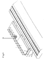
- FIG 1 shows a perspective view of a section of Platform according to the invention according to system I, which consists of two Basic sections (platform slabs 1) exist.
- the platform runs parallel to extend the rails, with the upper edge of the platform one must maintain the specified distance to the top edge of the rail.
- the Platform according to the invention is on a cleanliness layer 5 or one old platform 5 erected.
- On the foundations 4 are in one piece the spacer elements 3. These are each on the two end points of the foundations 4 are arranged.
- the spacer elements 3 on the one hand a defined support surface towards the platform slab 1; others are suitable as light and easily interchangeable elements, to perform the height and side adjustability function of the platform.
- the exchange of the spacer elements 3 will be without changing the Platform slabs 1 or the in-situ concrete foundations are possible, as is the platform to subsequently change its height or position.
- the Platform slabs 1 laid from foundation to foundation being due bridge the gap in a stable manner with their own load-bearing capacity.
- Figure 2 shows the construction according to the invention schematically in the Side view.
- longitudinal beams 2 can also be seen, which are formed on the underside of the platform slabs 1 and there for one Ensure longitudinal stability.
- Beams (see number 2 in Figures 1 and 3) for the stability of the platform slabs in the transverse direction.
- the beam changes the shape of the platform slab in this way (deviating of rectangular shape) that the composite platform slabs themselves adjust the given radii of curvature.
- the Platform slabs for this purpose are trapezoidal.
- some structures are shown as an example, e.g. a lamp mast 12 that can be placed anywhere, railings, seating, Waste containers etc.
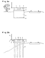
- FIG. 3 shows two variants of the platform according to the invention in a front view.
- FIG. 3a relates to the version with one-piece in-situ concrete foundations 4.
- the structure made up of cleanliness layer 5, foundation 4, spacer elements 3 and platform slab 1 with (transversely running) support beams 2 can be seen.
- empty pipes 6 can be seen, which run centrally below the platform plate 1 and can serve, for example, as cable protection pipes.
- the empty tubes 6 penetrate the cross beam 2.
- Figure 3b shows a similar basic structure, but here is the platform built on a pile foundation with the piles 4 '. This construction is in prefer difficult terrain and ground conditions, e.g. if the Platform being built on a dam. They are on the piles 4 ' Spacer elements 3, which can be designed as pile head beams. Furthermore are in Figure 3b arranged laterally on the platform edge Drainage channels 7, a cable trough 8, empty pipes 6, one in slots assembled railing 9 and a service hatch 10 recognizable.
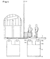
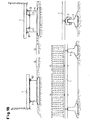
- FIG. 4 shows the front view of an alternative platform.
- Both Platforms are each based on the known structure Cleanliness layer 5, foundation 4, spacers 3 and platform slabs 1.
- Cleanliness layer 5 e.g., Weather protection devices and lighting measures. these can preferably in pre-assembled mounting sleeves with platform plates 1 get connected.
- the essentials of the construction according to FIG. 4 are the two-part ones Spacers 3a, 3b. These provide two support points, in which the longitudinal beam 2a, 2b are placed. With the two-piece Distribution of the spacer elements 3, it is possible to control the To influence platform slab 1. For this purpose, unevenly high Spacers 3a, 3b can be selected. It is either possible to use one to compensate for the horizontal inclination of the foundation 4 or to generate a corresponding inclination of the platform slab 1.
- the spacer elements also apply 3a, 3b in turn with projections in corresponding recesses in the Foundations 4 a. This way, without further, permanent Connection measures between the components ensures that the corresponding arrangement is stable against loading with transverse forces.
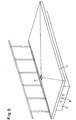
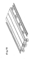
- FIG. 5 shows a platform slab 1 in perspective, in which a "negative Roof profile "creates a depression in the surface, at the lowest point of which Waste water drain 13 is arranged.
- a "negative Roof profile” creates a depression in the surface, at the lowest point of which Waste water drain 13 is arranged.
- Figure 6 shows a section of the plate side facing away from the track. You can see a c-profile 14, which serves to reinforce the edges, and this on site I-profile 15 to be attached (wide flange bracket of the HEA or HEB version).
- the non-positive connection with the plate 1 is with threaded sleeves 16 Shaft anchor, e.g. type PFEIFFER, a threaded rod and a nut 25, which is easily accessible from the outside.
- Threaded sleeves 16 Shaft anchor e.g. type PFEIFFER
- a threaded rod and a nut 25 which is easily accessible from the outside.
- Through openings in the top Flange either pre-defined in grid dimensions or on-site manufactured according to the requirements, e.g. Railing supports 17 torque stable and easy to install. Your attachment takes place in the lower area e.g. in a base plate 21 with screw thread.
- the Assembly time can also be shortened if the equipment elements are already connected to the support 19 (screwed or welded), before they
- the mounting bracket 19 can through a corresponding recess in the plate 1 flush to the concrete surface and with a permanently elastic Fugue 18 can be connected.
- the wearer can do the "drainage with negative roof profile" design variant but also be installed so that the top of the flange over the Concrete surface stands.
- the fastening rail described can also other materials (stainless steel, aluminum, plastics) or other profiles (composite c-profiles instead of (I-beams, special shapes) are provided.
- a Attachment to the upper or lower flange instead of (I-beams, special shapes).
- Figure 7 shows c-profile and I-profile in a schematic plan view and one Side view (side away from the track).
- Figure 8 shows the adaptation of the track-side plate edges 26 to predetermined ones Radii. Since all plate edges are drawn over the supporting structure 27 (Cantilever panels), the edges can be changed without the load-bearing capacity of the Endanger plate.
- the track-side edge 26 can be convex, concave or oblique be carried out.
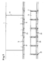
- Figure 9 shows the possibility of also on the side facing away from the track Change the edge course without endangering the load-bearing capacity. So can you e.g. natural barriers 30 (such as a ledge, a Tree) "dodge" or set design accents.
- natural barriers 30 such as a ledge, a Tree
- Figure 10 shows the connection of a mounting plate 32 to the system plate 1, e.g. to attach a weather shelter to it.
- the transition of both plates will manufactured by the mounting bracket 19.
- the mounting plate 32 can also retrofitted to the system panels equipped with a mounting bracket be connected.
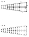
- Figure 11 shows the systems II and III in plan as a schematic diagram. Is shown the part of a central platform that tapers towards the end.
- System II consists of two or more adjacent to each other in the platform width Plates 1.
- the plan shows the continuous trough element 40 in the Middle, the two edge elements 41 running through the length and the in Grid of e.g. 9 m across the entire width of the platform Base beam 42.
- System III starts where the width of the platform is one single plate allows.
- the criteria here are the weight and the transport size the plate. It is shown e.g. a 7 m wide and 3 m long plate tapered on one side.
- the system III plates are on the outside of the two lying edge bar 41 on and partially, in the example every 9 m, on the Base bar 42.
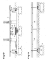
- Figure 12 shows the cross section of the platform system II.
- the trough element 40 is a cavity, in the supply lines 42 or other channels can be accommodated can.
- a possible attachment or foundation of is also indicated Platform structures, e.g. Platform roofs etc.
- the raising or lowering of the platform takes place via a spacer element 3 under the edge support 41.
- This spacer element is not continuous in length, but in each case placed on the base bar 42.
- Between edge supports 41 and Spacer 3 is a neoprene bearing 44.
- the drainage takes place in the figure via a half-groove 45 in the middle between the two Platform slabs.
- the water can flow through a recess in the trough element 40 be dissipated.
- a subsequent lateral shift of the Platform plate 1 is possible by spacing the two plates in the middle is enlarged (you can attach a larger half-channel 45). In this case both platform slabs can be pushed towards the track.
- a side Moving to one side is done by moving the complete Systems above the in-situ concrete foundation 4.
- the edge girder 41 can after be provided on the outside with a sound-absorbing surface.
- Figure 13 shows the longitudinal section of the same platform, namely System II. Occasionally required access to the interior of the trough channel 40, e.g. to change the drainage line is possible via a side Entry 46. Access to the cavity between the trough channel and the edge beam can be created via a manhole cover in the platform slab, which is in the color of the surface can be adjusted.
- Figure 14 shows the cross section of the platform system III.
- the structure is similar like System I, but without a central trough and with only one plate 1 over the total platform width.
- FIG. 15 shows the cross section of the system IV.
- the two platform slabs 1 (with a smaller width, e.g. ⁇ 7 m, there is also one Platform slab conceivable) are supported in the middle on a foundation finished part above.
- the edge bars 41 can with a sound-absorbing surface clad or made of a large-pored concrete be made on the surface.
- the foundations are composed of a frost-free lean concrete layer 49, on which two precast foundations 50 are put on.
- Figure 16 shows how the foundations of System IV are arranged and how Drainage of the platform can be provided.
- each plate has an inclination to a point. This Inclinations can already be provided in the panel in the precast plant.
- the drainage takes place in the middle between the two plates.
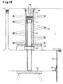
- the armature 52 is supported on a downward footplate 55 (e.g. 120 ⁇ 120 ⁇ 12 mm) anchored in the concrete foundation.
- a base plate 56 e.g. 120 ⁇ 120 ⁇ 12 mm
- a nut 57 e.g. M20-M27
- the resulting space can be created via the joint between the two panels be filled with concrete.
- the adjustment is guaranteed via the illustrated metal slide box 53, the seal a neoprene lip seal 54.
- this system can be used when filling with concrete cannot be lowered afterwards.
- the dimensions of the makeshift platform are variable. Its width is preferably between 2.40 m and 3.00 m. The length is preferably between 6 and 9 m, so that this system also minimizes costs and can be worked with simple device technology. Since the Makeshift platform to be installed several times at different locations, usually only certain grids are used.
- the makeshift platform consists of precast foundations 4 and a precast slab 1, which is supported on these foundations and is secured with stainless angles 61 against unintentional lateral displacement.
- the overhanging part can be varied as in the other systems.
- the precast foundations sit on a ballast bed and a thin layer of sand. Since the edges of the temporary restorations are straight, profiled sheets made of galvanized steel or stainless steel are provided on the floor, which cover the expansion joint. In a straight position, this joint is permanently elastic. Railings and lighter platform structures can be mounted on the outer edge using stainless steel brackets. As a rule, lighting masts etc. must be set up separately behind the platform edge.
- the cables are routed above the free space under the platform slab.
- FIG. 19 shows a perspective view for better illustration a central platform of the type described above.
- the system platform is based on a modular precast skeleton, with which, in an extremely short construction time, a new modern platform over one damaged platform or above the earth next to the formation can be installed.
- the Platform height between 38 cm above sea level (above the top of the rail) and 96 cm above sea level can be varied in stages at any time without great effort.
- the color, structure and texture of the surface of the covering can be discussed with the customer Bauherm individually defined and manufactured in consistently high quality become.
- Latitude and longitude parameters are based on the use case and the existing ones Transport options tailored, or also to a given Grid dimension of the user.
- roofs or weather protection devices can also be integrated according to a user specification, either according to the detailed sketch by connecting the required foundations to the Base beams or as individual foundations through a recess in the system plate.
- Standard traffic loads of 5 kN / m 2 for passenger traffic and 5 kN / m 2 for a 3-t baggage vehicle according to DS 804 Para. 105, Vol. 29 of DB AG can be used as load factors.
- the introduction of punctiform special loads, e.g. for supports for weather protection devices, etc. are possible and are permitted to a large extent without changing the planning.
- An essential component for the system platform of system I can be a special precast reinforced concrete can be used, which is in the construction based on the static system of a ⁇ plate.
- Panel thickness (or web height for system I) of the system panel are for everyone sufficiently conceivable operating conditions. Weight and Dimension of the element are on the work equipment in railway construction and that existing clearance profile matched.
- the plates are placed one below the other in the middle of the plate cantilevered area connected accordingly to height differences caused by bending or manufacturing, to compensate permanently.
- Precast elements made of reinforced concrete are also used as support elements, with a gradual height adjustment from 38 cm above sea level up to 96 cm üSO is guaranteed.
- the actual foundation is made of in-situ concrete.
- the dimensions of this Construction pits to be produced are generally chosen so that the stability the ballast bed is not endangered and no shoring is necessary.
- Removable connections guarantee a problem-free and quick conversion in the event of a future change in level.
- the transport anchors usually arranged in the surface of finished parts are avoided here in order not to disturb the uniform appearance of the surface by moving the plates with bands.
- the foundations are dimensioned so that the permissible ground pressure according to DIN 1054 or Eurocode 7 is observed. In the case of particularly bad ones Soil stabilization is provided in individual cases or a deep foundation is necessary.
- the covering side especially along the track side, must be equipped with a sure-footed, rough structure and a guide marking must be provided, which is indispensable as a visually and tactile orientation aid for special groups of people.
- a special surface quality which is characterized by a high abrasion value and insensitivity to environmental influences and the use of thawing agents, is particularly preferred.
- a particularly non-slip structure e.g. quintet pattern, checker plate pattern, other shapes
- a signal color e.g. Knob structure according to ADA and ACD, for the platform Pavement structure, various variations possible.
- the drainage is collected in a drainage channel and either fed to the ground in a septic tank or discharged into the sewage system.
- a cross slope of 1-2% of the system platform to the side facing away from the track or (as a rule) to the center reliably ensures that the water flows off evenly.
- a uniform gradient to the central drainage is ensured by the plate widths being able to be varied so that a uniform gradient is maintained from both sides.
- the water can through a special negative profiling of the plate surface in one or more Points are collected centrally and fed to a drain line.
- the platform system allows free access to the Cavity under the platform, e.g. via a manhole. in the Manhole cover the surface structure is continued.
- the cable routing takes place via cable protection tubes integrated in the plate System I, or through empty pipes arranged under the plate in the other systems. With cable connection boxes at regular intervals an uncomplicated supply of the platform facilities is guaranteed and enables the subsequent pulling in of cables.
- a cable trough can optionally be installed in the space under the plate, in which additional lines can be accommodated, for example, for the installation of a parallel communication network.
- the cavity under the platform slab can accommodate cable guides.
- the cavities can be made accessible through doors or openings in order to use these spaces as storage space for winter maintenance, for example.
Landscapes
- Engineering & Computer Science (AREA)
- Architecture (AREA)
- Civil Engineering (AREA)
- Structural Engineering (AREA)
- Bridges Or Land Bridges (AREA)
- Conveying And Assembling Of Building Elements In Situ (AREA)
- Refuge Islands, Traffic Blockers, Or Guard Fence (AREA)
- Transceivers (AREA)
- Pressure Welding/Diffusion-Bonding (AREA)
- Train Traffic Observation, Control, And Security (AREA)
- Discharge Heating (AREA)
Description
Allerdings hat diese Fertigung vor Ort auch mehrere Nachteile. Zum einen wird nämlich eine nur in Nuten befestigte verlorene Schalung verwendet. Daher ist aus rein statischen Gründen die Breite des Bahnsteigs begrenzt wegen der hohen Lasten, die von der Ortbetondecke auf die verlorene Schalung . anzurechnen sind.
Ferner muß Ortbeton bis zu 28 Tage abbinden, was die erforderliche Bauzeit verlängert. Außerdem können Witterungseinflüsse und Frost die Baustelle behindern.
Schließlich soll der Bahnsteig auch als provisorischer Bahnsteig oder Behelfsbahnsteig in solchen Fällen dienen können, wo ein Bahnsteig nur für eine bestimmte Dauer errichtet wird, z.B. in Form einer Bahnsteigverlängerung, weil für eine bestimmte Zeit längere Züge an einem Bahnsteig halten sollen oder für den Fall, daß ein Bahnsteig vorübergehend an einem anderen Ort errichtet werden soll und erst später in seine endgültige Lage kommt.
- dass der Bahnsteig komplett modular aufgebaut ist und aus austauschbaren Einzelkomponenten ohne dauerhafte Verbindung zwischen den Bauelementen besteht, so dass er von 38 bis 96 cm über der Schienenoberkante höhenvariabel und seitenvariabel ist, und dessen Auf- und Abbau sowie eine Auswechselung von Bauteilen ermöglicht wird,
- dass die Bahnsteigplatten an ihrer Unterseite Stützbereiche haben, innerhalb derer sie an beliebiger Stelle auf die Stützpunkte des Bahnsteigunterbaus aufgesetzt werden können, und/oder wobei der Bahnsteigunterbau an seiner Oberseite Stützbereiche hat, innerhalb derer die Bahnsteigplatten an beliebiger Stelle aufgesetzt werden können, so dass der Spielraum für eine Horizontalverschiebung der Bahnsteigplatten bis zu 5 bis 20 % der Bahnsteigbreite beträgt.
Die horizontale Lageveränderbarkeit kann so erzielt werden, daß die Bahnsteigplatten an ihrer. Unterseite Stützbereiche haben, innerhalb derer an beliebiger Stelle die Stützpunkte des Bahnsteigunterbaus positioniert werden können. Die "Stützpunkte des Bahnsteigunterbaus" sind dabei nicht nur als punktförmig zu verstehen, sondern können ihrerseits ausgedehnte Flächen sein, die ggf. nur teilweise mit den Bahnsteigplatten in Kontakt kommen.
Ferner hat die erfindungsgemäße Herstellung der Bahnsteigplatte aus verschiedenen vorgefertigten Fertigteilen, anstelle aus Ortbeton, verschiedene Vorteile gegenüber der DE 42 05 192 A1. So wird bei der vorgefertigten Bauweise der Bahnsteigplatte die Breite einer Bahnsteigplatte lediglich vorgegeben durch die maximal möglichen Transportmaße, bzw. Gewichte. Dagegen wird bei der DE 42 05 192 A1 die Breite des Bahnsteigs durch die verlorene Schalung begrenzt.
Zudem kann eine im Werk vorgefertigte Bahnsteigplatte sofort nach der Montage benutzt werden. Dies verkürzt die Behinderungszeiten vor Ort erheblich, da Ortbeton bekanntlich bis zu 28 Tage abbinden muß. Außerdem können Fertigteile auch bei extremen Temperaturen (Frost) montiert werden. Bei örtlichem Betonieren ist dies nicht der Fall. Auch hieraus ergibt sich eine größere Flexibilität in bezug auf die Bauzeit.
Ein weiterer wesentlicher Vorteil einer vorgefertigten Bahnsteigplatte im Gegensatz zu einer vor Ort betonierten besteht in der Aufteilung in einzelne, durch Fugen getrennte Plattenteile. Das Bahnsteigsystem ist damit mobil und wiederverwendbar, nicht nur aufhöhbar. Ein Fertigteilbahnsteig kann komplett in kurzer Zeit zurückgebaut werden. Es müssen lediglich die dauerelastischen Fugen zerschnitten und die Einzelteile herausgenommen werden. Bei dem in der DE 42 05 192 A1 dargestellten Bahnsteig handelt es sich dagegen um einen kompletten Bahnsteig als eine steife Platte bei der für einen Umbau der Beton zerschnitten werden muß. Durch die Zerstörung der Bewehrung ist die Wiederverwendbarkeit dabei sehr stark eingeschränkt.
Auch ist der Schalungsaufwand eines Bahnsteigabschnittes, der bei Bogenlagen im Übergangsbogen liegt, im Fertigteilwerk gemäß der Erfindung relativ gering. Es muß lediglich für jeden Abschnitt des Bahnsteigs die Bogenschalung angepaßt werden. Die in der DE 42 05 192 A1 dargestellte Gleitschalung ist dagegen im Übergangsbogen nicht verwendbar. Ein Fertigteil hat daher geringeren Schalungsaufwand und damit auch geringere Kosten.
Des weiteren ist das erfindungsgemäße Bahnsteigsystem komplett modular aufgebaut und aus austauschbaren Einzelkomponenten bestehend. Es ist deshalb sehr wartungsfreundlich, weil alle einzelnen Teile problemlos ausgetauscht werden können. Es müssen kein Betonabbruch oder Betonschnitte gemacht werden. In der Realität sind oft nachträglich an Bahnsteigen Anpassungen notwendig, z.B. das spätere Integrieren von Fahrleitungsmasten, von Signalen oder auch Schächten. Hier kann dann an der jeweiligen Stelle entweder die Platte komplett ausgetauscht werden oder auch nur teilweise verändert. Auch ist nur im Unterbau ein solcher Austausch möglich. Die vorgefertigte Bahnsteigplatte kann bereits im Werk eine nach den Wünschen des Anwenders konzipierte Oberfläche erhalten. Diese Oberfläche ist im späteren Gebrauch die begehbare Oberfläche des Bahnsteigs. Es ist also kein zusätzlicher Arbeitsgang notwendig, um z.B. den Bahnsteig zu verfliesen oder mit einer begehbaren Oberfläche zu versehen. Auch verschiedenfarbige Musterungen sind hier möglich. Im Gegensatz dazu muß bei der DE 42 05 192 A1 ein zusätzlicher Belag auf den Ortbeton aufgebracht werden. Die Werksfertigung garantiert auch hohe Maßgenauigkeit und Flexibilität in der Oberflächenbeschaffenheit, z.B. auch die Verwendung verschiedenfarbigen Betons und verschiedener Oberftächenrauhigkeiten in einer Platte. Bei Ortsbeton würde dies einen zusätzlichen Arbeitsgang bzw. auch durch die qualitativ schlechtere Verbindung von Oberbelag und Bahnsteigplatte einen höheren Wartungsaufwand bedeuten. Ein weiterer Vorteil der in der Schalung unterseitig liegenden späteren Oberfläche ist die größere Betondichte und Oberflächenhomogenität, die erzielbar ist (Planebene des Rütteltisches). Die erfindungsgemäße Systembauweise ermöglicht auch eine sehr hohe Maßgenauigkeit, da nur ein einmaliges Justieren der Bahnsteigplatte notwendig ist.
Bei der erfindungsgemäßen vorgefertigten Bahnsteigplatte können behindernde Anlagen im Bahnsteigbereich, wie z.B. vorhandene Maste, in das System integriert werden, d.h. Aussparungen und Plattengrößen sind wählbar, um beim Versetzen der Platten den Standort der behindernden Anlagen zu belassen.Ebensogut können einmal vorgesehene Aussparungen bei späterem Wegfall der behindernden Anlage wieder geschlossen werden. Auch können bestehende Tiefenentwässerungen zwischen Gleis und Bahnsteig bestehen bleiben bzw. es werden hierfür Aussparungen vorgesehen.
Die Auskragung der Bahnsteigplatte über den Randbalken ist variabel, vorzugsweise 70 cm (sog. Fluchtraum) kann aber auch Null sein.
So kann entweder entlang der Längskante der Bahnsteigplatte eine Abwasserrinne angeordnet sein, vorzugsweise beim Außenbahnsteig. Bei Mittelbahnsteigen und großen Bahnsteigbreiten ist auch eine Ableitung von Oberflächenwasser zu beiden Seiten durch entsprechende Neigung nach zwei Seiten möglich.
Eine weitere Variante ist die Mittelentwässerung. Hier kann in der Fuge zwischen zwei Bahnsteigplatten, ein Entwässerungskanal eingebaut werden mit einer Halbrinne/Kastenrinne unter der Fuge. Dieses Ablaufwasser wird je nach Längsgefälle der Platte z.B. alle 9 m herausgeführt und in die vorhandene Entwässerung abgeleitet. Das kann durch eine Aussparung in dem Mitteltrog (System II) geschehen. Auch System III und IV schaffen die Möglichkeit der Mittelentwässerung. Durch eine Aufkantung an der dem Gleis abgewandten Seite kann auch starker Regenwasserabfluß auf wenige Abläufe konzentriert werden.
Der Vorteil des erfindungsgemäßen Systems ist, daß mehrere Varianten der Regenwasserabführung möglich sind und es somit den Wünschen des Anwenders angepaßt werden kann.
Sie kann in verschiedenen Farben und Strukturen hergestellt werden. Insbesondere ist es möglich, für die Herstellung der Oberfläche verschiedene Betonzusammensetzungen zu verwenden. Dabei können zwei oder mehr verschiedene Betone eingesetzt werden, z.B. solche verschiedener Farben oder unterschiedlicher Zusammensetzungen (z.B. Glasfaserbeton und Beton mit anderen Zuschlägen). Diese können nach- und/oder nebeneinander in die Schalung eingebracht werden. Denkbar ist auch, daß sie in einer Rasterstruktur, in der sie nur durch Rasterfugen getrennt sind, angeordnet werden. Durch diese Verwendung verschiedener Betone kann sowohl eine ansprechende ästhetische (u.a. Farb-) Gestaltung der Bahnsteigplatten erzielt werden als auch vorteilhafte statische und funktionelle Eigenschaften.
Die abgehobenen Platten können sodann wiederverwendet werden. Dazu werden nur die dauerelastischen Fugen erneuert. Es entsteht kein Entsorgungsaufwand.
Dieses Verfahren läßt sich mit äußerst geringem Aufwand und ohne große und langandauernde Unterbrechungen des Schienenbetriebes durchführen. Insbesondere ist es auch möglich, kleinere Korrekturen im Zentimeterbereich durchzuführen. Anstelle des Austauschens der gesamten Distanzelemente kann dabei auch eine Erneuerung bzw. Aufstockung von Lagerelementen zwischen den Bauteilen des Fertigbausatzes erfolgen. Denn nach dem Stand der Technik ist es üblich, zwischen derartigen Bauelementen sogenannte Elastomerlager anzubringen, z.B. in der Form von Neoprenstreifen. Diese Lagerelemente werden zwischen Bahnsteigplatte und Distanzelement einerseits bzw. Distanzelement und Fundament andererseits angeordnet. Die verzahnte Profilierung der Bauteile verhindert sicher eine Horizontalverschiebung der Elastomerlager. Auch können Maßtoleranzen in der Bahnsteigplatte bzw. im Ortbetonfundament oder Fundamentfertigteil problemlos durch das Einbringen von schwundfreiem Vergußmörtel unter die Distanzelemente bzw. die Bahnsteigplatte ausgeglichen werden.
- Figur 1
- zeigt eine perspektivische Ansicht des erfindungsgemäßen Bahnsteiges (System I).
- Figur 2
- zeigt eine Seitenansicht des Bahnsteiges (System I).
- Figur 3a
- zeigt eine Frontansicht (Querschnitt) des Bahnsteiges mit einstückigen Fundamenten.
- Figur 3b
- zeigt eine Frontansicht (Querschnitt) des Bahnsteiges mit Pfahlfundamenten.
- Figur 4
- zeigt eine Frontansicht (Querschnitt) von zwei parallelen Bahnsteigen mit mehrstückigen Distanzelementen.
- Figur 5
- zeigt eine Perspektive der Bahnsteigplatte mit negativem Dachprofil.
- Figur 6
- zeigt den gleisabgewandten Plattenrand mit Montageträger.
- Figur 7
- zeigt eine schematische Draufsicht und Seitenansicht mit Montageträger.
- Figur 8
- zeigt ein Schema einer Bogenanpassung.
- Figur 9
- zeigt ein Schema einer Aussparung
- Figur 10
- zeigt schematisch den Anschluß einer Anbauplatte an die Systemplatte zur Gründung eines Wetterschutzhauses.
- Figur 11
- zeigt die Systeme II und III als Prinzipskizze.
- Figur 12
- zeigt den Querschnitt des Bahnsteigs System II.
- Figur 13
- zeigt Längsschnitt des Bahnsteigs System II.
- Figur 14
- zeigt den Querschnitt des Bahnsteigs System III.
- Figur 15
- zeigt den Querschnitt des Bahnsteigs System IV.
- Figur 16
- zeigt die Fundamente und Entwässerung (System IV).
- Figur 17
- zeigt die Höhenverstellbarbkeit bei System IV.
- Figur 18
- zeigt einen Behelfsbahnsteig.
- Figur 19
- zeigt eine perspektivische Ansicht eines Mittelbahnsteiges.
Figur 3a bezieht sich auf die Version mit einstückigen Ortbetonfundamenten 4. Auch hier ist der Aufbau aus Sauberkeitsschicht 5, Fundament 4, Distanzelementen 3 und Bahnsteigplatte 1 mit (querverlaufendem) Trägerbalken 2 erkennbar. Zusätzlich sind Leerrohre 6 erkennbar, welche mittig unterhalb der Bahnsteigplatte 1 verlaufen und z.B. als Kabelschutzrohre dienen können. An der Stirnseite der Bahnsteigplatte durchstoßen die Leerrohre 6 den Querträgerbalken 2.
Geländer und leichtere Bahnsteigaufbauten sind über rostfreie Winkel an der Außenkante montierbar. Beleuchtungsmaste etc. müssen in der Regel hinter der Bahnsteigkante gesondert gegründet werden. Die Kabelführung erfolgt über dem Freiraum unter der Bahnsteigplatte. In diesem Fall sind Aussparungen für Leerrohre in den Fundamenten vorzusehen. Um die Höhenverstellbarkeit zu gewährleisten, besteht die Möglichkeit, ein Fertigteil-Zwischenstück 3 vorzusehen, dessen Auflagerfläche zur Betonteilfertigplatte nicht größer sein darf als die ursprüngliche Auflagerfläche des Fertigteilfundamentes, damit die Lasten aus der Platte senkrecht in das Fundament gehen (Auflagerfläche ca. 20 cm).
Für Ausführung der Texturen und Muster für die Belagobertläche gibt es vielfältige Gestaltungsmöglichkeiten, was auch die Wahl der Ausstattungsgegenstände betrifft.
Ebenso möglich ist die Integration automatischer Abtauanlagen auf der Basis elektrischer Bodenbeheizungen oder die Nutzung des Raumes unter der Systembahnsteigplatte als bike & rail- Station mit abschließbaren Fahrradboxen, als Ort für Gepäckaufbewahrungs, etc..
Die üblicherweise in der Oberfläche von Fertigteilen angeordneten Transportanker werden hier vermieden, um die einheitliche Optik der Oberfläche nicht zu stören, indem die Platten mit Bändern bewegt werden.
Auf Wunsch des Anwenders ist die Belagseite, insbesondere entlang der Gleisseite, mit einer trittsicheren, rauhen Struktur auszurüsten und eine Leitmarkierung vorzusehen, die als eine optisch und taktil wahrnehmbare Orientierungshilfe für besondere Personengruppen unerläßlich ist. Eine besondere Oberflächengüte, die sich durch einen hohen Abrasionswert und Unempfindlichkeit gegen Umwelteinflüsse und den Einsatz von Taumitteln auszeichnet, ist dabei besonders bevorzugt.
| für den Bereich der Bahnsteigkante | ein 30 -50 cm breiter Streifen mit einer besonders griffigen Struktur (z.B. Quintettmuster, Riffelblechmuster, andere Formen), |
| für den taktilen Leitstreifen | eine 25 cm breite mit einer Signalfarbe versehene Leitmarkierung, z.B. Noppenstruktur nach ADA und ACD, |
| für den Bahnsteig | Pflasterstruktur, diverse Variationen möglich. |
Eine Querneigung von 1-2 % des Systembahnsteiges zur gleisabgewandten Seite oder (in der Regel) zur Mitte sorgt zuverlässig für ein gleichmäßiges Abfließen des Wassers.
Bei unterschiedlichen Höhen der beiden am Mittelbahnsteig entlang führenden Gleise wird ein gleichmäßiges Gefälle zur Mittelentwässerung hin gewährleistet, indem die Plattenbreiten variiert werden können, so daß von beiden Seiten ein gleichmäßiges Gefälle eingehalten wird.
Gleichzeitig kann der Hohlraum unter der Bahnsteigplatte Kabetführungen aufnehmen. Die Hohlräume können durch Türen oder Öffnungen begehbar gemacht werden, um diese Räume z.B. als Lagerfläche für den Winterdienst zu nutzen.
- 1
- Bahnsteigplatte
- 2
- Trägerbalken
- 3
- Distanzelemente
- 4,4'
- Fundamente
- 5
- Sauberkeitsschicht
- 6
- Leerrohre
- 7
- Entwässerungsrinne
- 8
- Kabeltrog
- 9
- Geländer
- 10
- Service-Luke
- 11
- Quertrasse
- 12
- Leuchtenmast
- 13
- Abfluß
- 14
- C-Profil
- 15
- I-Profil
- 16
- Gewindehülsen
- 17
- Geländerstütze
- 18
- dauerelastische Fuge
- 19
- Montageträger
- 20
- Schrauben
- 21
- Fußplatte
- 22
- Geländeraufnahme
- 23
- Stoß Montageträger
- 24
- Glasfüllung
- 25
- Verschraubung mit Bahnsteigplatte
- 26
- Plattenkante zum Gleis
- 27
- Tragekonstruktion
- 28
- Gleisachse
- 29
- Bahnsteigachse
- 30
- Barriere
- 31
- Aussparung
- 32
- Anbauplatte
- 33
- Stütze für Wetterschutzhaus
- 34
- Dachlinie Wetterschutzhaus
- 35
- Fundament
- 36
- Seitenwand (verglast)
- 37
- Pylon/Tragelement
- 38
- Anbauelement/Vitrine
- 39
- Tragstütze
- 40
- Trogelement
- 41
- Randelement
- 42
- Grundbalken
- 43
- Versorgungsleitungen
- 44
- Neopren-Lager
- 45
- Halbrinne
- 46
- Einstieg
- 47
- Alter Bahnsteig
- 48
- Lastausbreitung
- 49
- Magerbetonschicht
- 50
- Fertigteilfundament
- 51
- Stahlrohr
- 52
- Anker
- 53
- Blechgleitkasten
- 54
- Neoprenlippendichtung
- 55
- Fußplatte
- 56
- Grundplatte
- 57
- Mutter
- 58
- Spiral-Bewehrung
- 59
- Aufsatzring
- 60
- Elektro-Schrauber
- 61
- Winkel
Claims (25)
- Fertigbausatz zur Erstellung eines veränderbaren Bahnsteigs enthaltend eine oder mehrere Bahnsteigplatten (1) und einen Bahnsteigunterbau mit Fundamenten (4), dadurch gekennzeichnet,dass der Bahnsteig komplett modular aufgebaut ist und aus austauschbaren Einzelkomponenten ohne dauerhafte Verbindung zwischen den Bauelementen besteht, so dass er von 38 bis 96 cm über der Schienenoberkante höhenvariabel und seitenvariabel ist, und dessen Auf- und Abbau sowie eine Auswechselung von Bauteilen ermöglicht wird,dass die Bahnsteigplatten (1) an ihrer Unterseite Stützbereiche haben, innerhalb derer sie an beliebiger Stelle auf die Stützpunkte des Bahnsteigunterbaus aufgesetzt werden können, und/oder wobei der Bahnsteigunterbau an seiner Oberseite Stützbereiche hat, innerhalb derer die Bahnsteigplatten (1) an beliebiger Stelle aufgesetzt werden können, so dass der Spielraum für eine Horizontalverschiebung der Bahnsteigplatten bis zu 5 bis 20 % der Bahnsteigbreite beträgt.
- Fertigbausatz nach Anspruch 1,
dadurch gekennzeichnet, daß er ein oder mehrere Distanzelemente (3) enthält, welche im montierten Zustand zwischen den Bahnsteigplatten (1) und Fundamenten (4) angeordnet sind, und welche ohne Beschädigung der Bahnsteigplatten (1), Fundamente (4) und Distanzelemente (3) austauschbar sind. - Fertigbausatz nach Anspruch 2,
dadurch gekennzeichnet, daß die Bahnsteigplatten (1) auf den Distanzelementen (3) und/oder die Distanzelemente (3) auf den Fundamenten (4) in verschiedenen horizontalen Lagen stabil aufgelegt werden können, bzw. der Abstand der Fundamente variiert werden kann. - Fertigbausatz nach einem der Ansprüche 2 oder 3,
dadurch gekennzeichnet, daß die Bahnsteigplatte (1) auf den Distanzelementen (3) lösbar verbunden aufliegt und/oder die Distanzelemente (3) auf den Fundamenten (4) lösbar verbunden aufliegen, wobei die lösbare Verbindung eine Verschraubung sein kann. - Fertigbausatz nach einem der Ansprüche 2 bis 4,
dadurch gekennzeichnet, daß die Bahnsteigplatte (1) und die Distanzelemente (3) und/oder die Distanzelemente (3) und die Fundamente (4) verzahnt sind oder eine komplementäre, ineinandergreifende Formgebung haben, so daß keine unbeabsichtigte Parallelverschiebung der Teile gegeneinander möglich ist. - Fertigbausatz nach einem der Ansprüche 2 bis 5,
dadurch gekennzeichnet, daß sich die Bahnsteigplatten (1) und/oder die Distanzelemente (3) einstückig über die Breite des Bahnsteigs erstrecken. - Fertigbausatz nach einem der Ansprüche 2 bis 6,
dadurch gekennzeichnet, daß mindestens zwei Distanzelemente (3a,3b) zwischen den Bahnsteigplatten (1) und jedem Fundament (4) angeordnet werden. - Fertig bausatz nach einem der Ansprüche 2 bis 7,
dadurch gekennzeichnet, daß zwischen Bahnsteigplatte (1) und Distanzelementen (3) Trägerelemente (40, 41) angeordnet sind. - Fertigbausatz nach Anspruch 8,
dadurch gekennzeichnet, daß die Trägerelemente (40, 41) parallel zur Schiene von Fundament zu Fundament verlaufen. - Fertigbausatz nach einem der Ansprüche 8 oder 9,
dadurch gekennzeichnet, daß es sich bei den Trägerelementen um Trägerbalken (41) oder U-förmige Trogelemente (40) handelt, wobei die Trogelemente (40) vorzugsweise derart unter zwei in der Bahnsteigbreite nebeneinanderliegenden Bahnsteigplatten (1) liegen, daß jeweils ein U-Schenkel eine der Bahnsteigplatten (1) trägt. - Fertigbausatz nach einem der Ansprüche 2 bis 10,
dadurch gekennzeichnet, daß zwischen den Distanzelementen (3) und den Fundamenten (4) Grundbalken (42) liegen, weiche vorzugsweise Fertigbauteile sind und quer zur Schienenrichtung von Fundamenten (4) zu Fundamenten (4) verlaufen. - Fertigbausatz nach einem der Ansprüche 1 bis 11,
dadurch gekennzeichnet, daß die Bahnsteigplatte (1) über höhenverstellbare Füße (52) auf dem Bahnsteigunterbau abgestützt ist. - Fertigbausatz nach Anspruch 12,
dadurch gekennzeichnet, daß die höhenveränderbaren Füße aus einem Gewindeanker (52) bestehen, der verschieden tief in die Bahnsteigplatte (1) oder den Bahnsteigunterbau eingeschraubt werden kann. - Fertigbausatz nach Anspruch 12 oder 13,
dadurch gekennzeichnet, daß der Gewindeanker (52) auf einer Fußplatte (55) gegengefagert ist. - Fertigbausatz nach einem der Ansprüche 1 bis 14,
dadurch gekennzeichnet, daß die Bahnsteigplatte (1) an ihrer Unterseite parallelverlaufende Trägerbalken (2,2a,2b) angeformt aufweist. - Fertigbausatz nach einem der Ansprüche 1 bis 15,
dadurch gekennzeichnet, daß in die Bahnsteigplatte (1) Aussparungen für Kabelschutzrohre (6) integriert sind. - Fertigbausatz nach einem der Ansprüche 1 bis 16,
dadurch gekennzeichnet, daß die Bahnsteigplatte (1) Montagehülsen für Bahnsteigaufbauten aufweist. - Fertigbausatz nach einem der Ansprüche 1 bis 17,
dadurch gekennzeichnet, daß die Bahnsteigplatte (1) eine von der Ebene abweichende Profilierung zur Abteilung von Oberflächenwasser hat, insbesondere eine negative Profilierung zur Sammlung des Oberflächenwassers in einer oder mehreren Senken. - Fertigbausatz nach einem der Ansprüche 1 bis 18,
dadurch gekennzeichnet, daß die Bahnsteigplatte (1) eine entlang ihrer Längskante verlaufende Abwasserrinne (7) aufweist. - Fertigbausatz nach einem der Ansprüche 1 bis 19,
dadurch gekennzeichnet, daß die Bahnsteigplatte (1) ein Gewicht von weniger als 10000 kg, vorzugsweise weniger als 8000 kg, hat. - Fertigbausatz nach einem der Ansprüche 1 bis 20,
dadurch gekennzeichnet, daß die Bahnsteigplatte (1) eine Breite von 2 bis 5 m, vorzugsweise 2,5 bis 3,0 m, und eine Länge von 4 bis 10 m, vorzugsweise 5 bis 7,5 m, hat. - Fertigbausatz nach einem der Ansprüche 1 bis 21,
dadurch gekennzeichnet, daß die Bahnsteigplatte (1) mit einer rutschsicheren Oberfläche und/oder Sicherheits- und Leitsystemen ausgestattet ist. - Fertigbausatz nach einem der Ansprüche 1 bis 22,
dadurch gekennzeichnet, daß die Bahnsteigplatte (1) hergestellt wird durch Einsatz verschiedener Betonzusammensetzungen, insbesondere Betone verschiedener Farbe und/oder Zuschläge, vorzugsweise unter Verwendung von Glasfaserbeton. - Fertigbausatz nach Anspruch 23,
dadurch gekennzeichnet, daß die verschiedenen Betone nebeneinander, vorzugsweise in einer Rasterstruktur mit Arbeitsfugen in der Bahnsteigplatte (1 ) eingebracht werden. - Fertigbausatz nach einem der Ansprüche 1 bis 24,
dadurch gekennzeichnet, daß die Bahnsteigplatte (1) eine für die Erzeugung von Krümmungsverläufen geeignete Form hat.
Applications Claiming Priority (3)
| Application Number | Priority Date | Filing Date | Title |
|---|---|---|---|
| DE19641800 | 1996-10-10 | ||
| DE19641800A DE19641800A1 (de) | 1996-10-10 | 1996-10-10 | Modularer Bahnsteigbausatz |
| PCT/EP1997/005571 WO1998015691A1 (de) | 1996-10-10 | 1997-10-09 | Modularer bahnsteigbausatz |
Publications (2)
| Publication Number | Publication Date |
|---|---|
| EP0865540A1 EP0865540A1 (de) | 1998-09-23 |
| EP0865540B1 true EP0865540B1 (de) | 2004-01-02 |
Family
ID=7808376
Family Applications (1)
| Application Number | Title | Priority Date | Filing Date |
|---|---|---|---|
| EP97945810A Expired - Lifetime EP0865540B1 (de) | 1996-10-10 | 1997-10-09 | Fertigbausatz zur erstellung eines veränderbaren bahnsteigs |
Country Status (7)
| Country | Link |
|---|---|
| US (1) | US6173653B1 (de) |
| EP (1) | EP0865540B1 (de) |
| AT (1) | ATE257197T1 (de) |
| AU (1) | AU5117998A (de) |
| DE (2) | DE19641800A1 (de) |
| PL (1) | PL190117B1 (de) |
| WO (1) | WO1998015691A1 (de) |
Cited By (3)
| Publication number | Priority date | Publication date | Assignee | Title |
|---|---|---|---|---|
| DE202009005016U1 (de) | 2009-07-14 | 2009-09-17 | Hering Bau Gmbh & Co. Kg | Modular aufgebauter Bahnsteig |
| EP2278071A1 (de) | 2009-06-18 | 2011-01-26 | MSB-Management GmbH | Modulare Bahnsteigkante mit demontierbarer Bahnsteigkantenplatte |
| DE202013100857U1 (de) | 2013-02-28 | 2013-04-18 | Hering Bau Gmbh & Co. Kg | Bahnsteigaufhöhungs- und Sanierungssystem |
Families Citing this family (30)
| Publication number | Priority date | Publication date | Assignee | Title |
|---|---|---|---|---|
| ATE338168T1 (de) * | 1998-07-15 | 2006-09-15 | Corus Uk Ltd | Bahnsteigstruktur |
| DE19855511A1 (de) * | 1998-10-17 | 2000-05-04 | Euka Gmbh Ingenieur Consulting | Fertigbausatz für die Erstellung einer Plattform, insbesondere eines Bahnsteiges |
| NL1012567C2 (nl) * | 1999-07-12 | 2001-01-15 | Compatech B V | Stelrand voor keerwanden en werkwijze voor het aanbrengen en stellen van de rand. |
| GB2378193A (en) * | 2001-08-03 | 2003-02-05 | Laing Rail Ltd | Railway platform construction |
| ATE368771T1 (de) | 2002-06-10 | 2007-08-15 | Karl-Heinz Winter | Modulares bahnsteigsystem |
| BE1015505A3 (nl) * | 2003-05-05 | 2005-05-03 | Composite Damping Material Nv | Tussen een trein en een platform te plaatsen boordelement. |
| GB0310517D0 (en) * | 2003-05-07 | 2003-06-11 | Middleton Jonathan | Rail system |
| FR2875463B1 (fr) * | 2004-09-17 | 2006-12-15 | Csm Chaudronnerie De Saint Mar | Dispositif pour creer un quai a usage temporaire, pour les usagers d'un moyen de transport |
| US7779581B2 (en) * | 2007-05-09 | 2010-08-24 | Ada Solutions, Inc. | Replaceable wet-set tactile warning surface unit and method of installation and replacement |
| FR2918339A1 (fr) * | 2007-07-02 | 2009-01-09 | Alstom Transport Sa | Vehicule ferroviaire et dispositif d'acces audit vehicule |
| DE202009004754U1 (de) | 2009-04-29 | 2009-07-02 | Hering Bau Gmbh & Co. Kg | Modulares System zur Überdachung von Bahnsteigen |
| RU2403337C1 (ru) * | 2009-04-29 | 2010-11-10 | Общество с ограниченной ответственностью "Научно-технологический испытательный центр "АпАТэК-Дубна" | Платформа |
| DE102010019891A1 (de) | 2010-05-07 | 2011-11-10 | Hsp Spengler Gmbh & Co.Kg | Bahnsteig in Fertigteilbauweise |
| US8920066B1 (en) | 2011-01-12 | 2014-12-30 | Tuf-Tite, Inc. | Tactile sidewalk surface |
| DE102013100228A1 (de) * | 2013-01-10 | 2014-07-10 | Triple S-Gmbh | Bahnsteiginstallationseinrichtung für einen Bahnsteig |
| FR3032728B1 (fr) * | 2015-02-17 | 2017-07-21 | Metrolab | Procede de deploiement modulaire de quais |
| CN105778934A (zh) * | 2016-04-06 | 2016-07-20 | 中国五冶集团有限公司 | 基于焦炉炉体砌筑施工的三维控制砌筑方法 |
| CN106703449A (zh) * | 2017-01-24 | 2017-05-24 | 北京交通大学 | 一种基于装配式技术的单轨交通车站 |
| GB2562305B (en) * | 2017-05-12 | 2020-01-15 | Geoffrey Osborne Ltd | A coper unit for an edge of a platform |
| CN107190658B (zh) * | 2017-07-27 | 2023-07-11 | 四川睿铁科技有限责任公司 | 一种钢制自由框拼装式铁路疏散救援站台 |
| US10920378B2 (en) | 2018-01-19 | 2021-02-16 | Tuf-Tite, Inc. | Stamped steel detectable warning tile and method of manufacture |
| JP2019137213A (ja) * | 2018-02-09 | 2019-08-22 | 有限会社弘栄工業 | ホーム柵 |
| CN110196568B (zh) * | 2018-02-26 | 2022-06-24 | 宝山钢铁股份有限公司 | 行车抓取板坯的方法 |
| US10954679B2 (en) | 2018-06-11 | 2021-03-23 | International Business Machines Corporation | Dynamic platform creation |
| RU2725972C1 (ru) * | 2019-09-06 | 2020-07-08 | Общество с ограниченной ответственностью "Андромета" | Сборно-разборная железнодорожная платформа и способ её перемещения |
| CN111794040B (zh) * | 2020-06-30 | 2022-05-17 | 中铁二院工程集团有限责任公司 | 一种支撑站台板的异形支挡结构及施工方法 |
| CN112942153A (zh) * | 2021-01-26 | 2021-06-11 | 哈尔滨工业大学 | 道路安全岛及其施工方法 |
| IT202100031037A1 (it) * | 2021-12-10 | 2023-06-10 | Alfio Giovanni Torrisi | Struttura prefabbricata modulare integrata in cemento armato per l’adeguamento dell’altezza del piano di calpestio di banchine ferroviarie |
| JP7832057B2 (ja) * | 2022-06-03 | 2026-03-17 | 東日本旅客鉄道株式会社 | 駅ホームの補強構造 |
| DE102024105971A1 (de) | 2024-03-01 | 2025-09-04 | Hering Bau Gmbh & Co. Kg | Schnell installierbare, genau positionierbare Systeme baulicher Einrichtungen und Verfahren |
Family Cites Families (9)
| Publication number | Priority date | Publication date | Assignee | Title |
|---|---|---|---|---|
| DE148132C (de) * | ||||
| US2652783A (en) * | 1949-06-02 | 1953-09-22 | Whiting Corp | Crossover bridge and operating mechanism |
| EP0357161B1 (de) * | 1988-08-01 | 1992-10-28 | Otto Frenzel Bauunternehmen | Bahnsteig |
| DE3826096A1 (de) * | 1988-08-01 | 1990-02-15 | Frenzel Otto Bauunternehmen | Bausatz fuer bahnsteig |
| DE4205192C2 (de) * | 1992-02-20 | 1995-10-12 | Euka Bauelemente Verkaufsgesel | Bahnsteig |
| DE4316203A1 (de) * | 1992-05-20 | 1993-11-25 | Stewing Beton & Fertigteilwerk | Bausatz zum Erstellen eines Bahnsteiges in Fertigteilbauweise |
| DE9304059U1 (de) * | 1993-03-19 | 1993-09-16 | Schreck-Mieves GmbH, 50226 Frechen | Bahnsteig |
| DE4431470A1 (de) * | 1994-09-03 | 1996-03-07 | Mannheimer Verkehrs Ag Mvg | Bahnsteig für eine Haltestelle für Personenbeförderungsfahrzeuge |
| DE29503328U1 (de) * | 1995-02-17 | 1995-04-13 | Otto Frenzel, Bauunternehmen, 31084 Freden | Bahnsteig |
-
1996
- 1996-10-10 DE DE19641800A patent/DE19641800A1/de not_active Withdrawn
-
1997
- 1997-10-09 AU AU51179/98A patent/AU5117998A/en not_active Abandoned
- 1997-10-09 EP EP97945810A patent/EP0865540B1/de not_active Expired - Lifetime
- 1997-10-09 WO PCT/EP1997/005571 patent/WO1998015691A1/de not_active Ceased
- 1997-10-09 US US09/091,206 patent/US6173653B1/en not_active Expired - Lifetime
- 1997-10-09 AT AT97945810T patent/ATE257197T1/de active
- 1997-10-09 PL PL97327189A patent/PL190117B1/pl not_active IP Right Cessation
- 1997-10-09 DE DE59711169T patent/DE59711169D1/de not_active Expired - Lifetime
Cited By (3)
| Publication number | Priority date | Publication date | Assignee | Title |
|---|---|---|---|---|
| EP2278071A1 (de) | 2009-06-18 | 2011-01-26 | MSB-Management GmbH | Modulare Bahnsteigkante mit demontierbarer Bahnsteigkantenplatte |
| DE202009005016U1 (de) | 2009-07-14 | 2009-09-17 | Hering Bau Gmbh & Co. Kg | Modular aufgebauter Bahnsteig |
| DE202013100857U1 (de) | 2013-02-28 | 2013-04-18 | Hering Bau Gmbh & Co. Kg | Bahnsteigaufhöhungs- und Sanierungssystem |
Also Published As
| Publication number | Publication date |
|---|---|
| DE59711169D1 (de) | 2004-02-05 |
| PL327189A1 (en) | 1998-11-23 |
| DE19641800A1 (de) | 1998-04-23 |
| PL190117B1 (pl) | 2005-11-30 |
| EP0865540A1 (de) | 1998-09-23 |
| ATE257197T1 (de) | 2004-01-15 |
| WO1998015691A1 (de) | 1998-04-16 |
| AU5117998A (en) | 1998-05-05 |
| US6173653B1 (en) | 2001-01-16 |
Similar Documents
| Publication | Publication Date | Title |
|---|---|---|
| EP0865540A1 (de) | Modularer bahnsteigbausatz | |
| EP3521557B1 (de) | Multifunktionsrahmen für röhrenartige bauwerke | |
| EP0563436B1 (de) | Transportable Raumzelle und Verfahren zum herstellen einer Raumzelle | |
| AT391499B (de) | Eisenbahnoberbau, insbesondere fuer schienenfahrzeuge mit sehr hohen fahrgeschwindigkeiten | |
| EP2088244A1 (de) | Stahlbeton oder Verbundbrücke und Verfahren zu ihrer Herstellung | |
| EP0357161B1 (de) | Bahnsteig | |
| DE4316203A1 (de) | Bausatz zum Erstellen eines Bahnsteiges in Fertigteilbauweise | |
| DE4135445C2 (de) | Bahnsteigkante | |
| EP2166149B2 (de) | Gleiskörperformteileinheit | |
| EP1371781A1 (de) | Modulares Bahnsteigsystem | |
| EP1106737A2 (de) | Bahnsteig | |
| DE19854246A1 (de) | Verfahren und System zum Bau und Umbau von Bahnsteigen mit veränderbaren Höhen | |
| DE29723956U1 (de) | Modularer Bahnsteigbausatz | |
| AT527289A1 (de) | Bogenhaus | |
| DE29912398U1 (de) | Bahnsteigsystem aus Betonfertigteilen | |
| DE19959236C1 (de) | Bahnsteig | |
| DE10140318A1 (de) | Bahnsteig | |
| DE19818338C1 (de) | Bahnsteigsystem und Verfahren zur Erstellung eines Bahnsteiges | |
| DE10300241A1 (de) | Verfahren zum preisgünstigen Umbau von Bahnsteigen und Verkehrswegen | |
| DE1434752C (de) | Mehrere Arbeitsstande einer Fahr zeugwerkstatte umfassende, durchgehende Arbeits grube | |
| DE1434752B1 (de) | Mehrere Arbeitsstaende einer Fahrzeugwerkstaette umfassende,durchgehende Arbeitsgrube | |
| DE29922297U1 (de) | Stahl-Beton-Decke | |
| DE19713990C2 (de) | Bahnsteigsystem und Verfahren zur Erstellung eines Bahnsteiges | |
| DE8809764U1 (de) | Bausatz für Bahnsteig | |
| DE19650105A1 (de) | Tragkonstruktion |
Legal Events
| Date | Code | Title | Description |
|---|---|---|---|
| PUAI | Public reference made under article 153(3) epc to a published international application that has entered the european phase |
Free format text: ORIGINAL CODE: 0009012 |
|
| 17P | Request for examination filed |
Effective date: 19980604 |
|
| AK | Designated contracting states |
Kind code of ref document: A1 Designated state(s): AT BE CH DE FR LI NL |
|
| 17Q | First examination report despatched |
Effective date: 20020129 |
|
| GRAP | Despatch of communication of intention to grant a patent |
Free format text: ORIGINAL CODE: EPIDOSNIGR1 |
|
| RTI1 | Title (correction) |
Free format text: CONSTRUCTION KIT FOR THE CONSTRUCTION OF A MODULAR STATION PLATFORM |
|
| GRAS | Grant fee paid |
Free format text: ORIGINAL CODE: EPIDOSNIGR3 |
|
| GRAA | (expected) grant |
Free format text: ORIGINAL CODE: 0009210 |
|
| AK | Designated contracting states |
Kind code of ref document: B1 Designated state(s): AT BE CH DE FR LI NL |
|
| REG | Reference to a national code |
Ref country code: CH Ref legal event code: EP |
|
| REF | Corresponds to: |
Ref document number: 59711169 Country of ref document: DE Date of ref document: 20040205 Kind code of ref document: P |
|
| REG | Reference to a national code |
Ref country code: CH Ref legal event code: NV Representative=s name: R. A. EGLI & CO. PATENTANWAELTE |
|
| ET | Fr: translation filed | ||
| PLBE | No opposition filed within time limit |
Free format text: ORIGINAL CODE: 0009261 |
|
| STAA | Information on the status of an ep patent application or granted ep patent |
Free format text: STATUS: NO OPPOSITION FILED WITHIN TIME LIMIT |
|
| 26N | No opposition filed |
Effective date: 20041005 |
|
| REG | Reference to a national code |
Ref country code: FR Ref legal event code: ST Effective date: 20080630 |
|
| PGFP | Annual fee paid to national office [announced via postgrant information from national office to epo] |
Ref country code: FR Payment date: 20061010 Year of fee payment: 10 |
|
| PG25 | Lapsed in a contracting state [announced via postgrant information from national office to epo] |
Ref country code: FR Free format text: LAPSE BECAUSE OF NON-PAYMENT OF DUE FEES Effective date: 20071031 |
|
| PGFP | Annual fee paid to national office [announced via postgrant information from national office to epo] |
Ref country code: BE Payment date: 20121129 Year of fee payment: 16 |
|
| PGFP | Annual fee paid to national office [announced via postgrant information from national office to epo] |
Ref country code: NL Payment date: 20121024 Year of fee payment: 16 |
|
| BERE | Be: lapsed |
Owner name: *HERING G.M.B.H. & CO. K.G. VERWALTUNGSGESELLSCHAF Effective date: 20131031 |
|
| REG | Reference to a national code |
Ref country code: NL Ref legal event code: V1 Effective date: 20140501 |
|
| PG25 | Lapsed in a contracting state [announced via postgrant information from national office to epo] |
Ref country code: NL Free format text: LAPSE BECAUSE OF NON-PAYMENT OF DUE FEES Effective date: 20140501 |
|
| PG25 | Lapsed in a contracting state [announced via postgrant information from national office to epo] |
Ref country code: BE Free format text: LAPSE BECAUSE OF NON-PAYMENT OF DUE FEES Effective date: 20131031 |
|
| PGFP | Annual fee paid to national office [announced via postgrant information from national office to epo] |
Ref country code: CH Payment date: 20141027 Year of fee payment: 18 |
|
| PGFP | Annual fee paid to national office [announced via postgrant information from national office to epo] |
Ref country code: AT Payment date: 20141028 Year of fee payment: 18 |
|
| REG | Reference to a national code |
Ref country code: CH Ref legal event code: PL |
|
| REG | Reference to a national code |
Ref country code: AT Ref legal event code: MM01 Ref document number: 257197 Country of ref document: AT Kind code of ref document: T Effective date: 20151009 |
|
| PG25 | Lapsed in a contracting state [announced via postgrant information from national office to epo] |
Ref country code: CH Free format text: LAPSE BECAUSE OF NON-PAYMENT OF DUE FEES Effective date: 20151031 Ref country code: LI Free format text: LAPSE BECAUSE OF NON-PAYMENT OF DUE FEES Effective date: 20151031 |
|
| PG25 | Lapsed in a contracting state [announced via postgrant information from national office to epo] |
Ref country code: AT Free format text: LAPSE BECAUSE OF NON-PAYMENT OF DUE FEES Effective date: 20151009 |
|
| PGFP | Annual fee paid to national office [announced via postgrant information from national office to epo] |
Ref country code: DE Payment date: 20160922 Year of fee payment: 20 |
|
| REG | Reference to a national code |
Ref country code: DE Ref legal event code: R071 Ref document number: 59711169 Country of ref document: DE |