EP0856676A1 - Kupplungseinheit - Google Patents
Kupplungseinheit Download PDFInfo
- Publication number
- EP0856676A1 EP0856676A1 EP98101491A EP98101491A EP0856676A1 EP 0856676 A1 EP0856676 A1 EP 0856676A1 EP 98101491 A EP98101491 A EP 98101491A EP 98101491 A EP98101491 A EP 98101491A EP 0856676 A1 EP0856676 A1 EP 0856676A1
- Authority
- EP
- European Patent Office
- Prior art keywords
- driving force
- transmission system
- electromagnet
- force transmission
- clutch
- Prior art date
- Legal status (The legal status is an assumption and is not a legal conclusion. Google has not performed a legal analysis and makes no representation as to the accuracy of the status listed.)
- Granted
Links
Images


Classifications
-
- F—MECHANICAL ENGINEERING; LIGHTING; HEATING; WEAPONS; BLASTING
- F16—ENGINEERING ELEMENTS AND UNITS; GENERAL MEASURES FOR PRODUCING AND MAINTAINING EFFECTIVE FUNCTIONING OF MACHINES OR INSTALLATIONS; THERMAL INSULATION IN GENERAL
- F16D—COUPLINGS FOR TRANSMITTING ROTATION; CLUTCHES; BRAKES
- F16D27/00—Magnetically- or electrically- actuated clutches; Control or electric circuits therefor
- F16D27/10—Magnetically- or electrically- actuated clutches; Control or electric circuits therefor with an electromagnet not rotating with a clutching member, i.e. without collecting rings
- F16D27/108—Magnetically- or electrically- actuated clutches; Control or electric circuits therefor with an electromagnet not rotating with a clutching member, i.e. without collecting rings with axially movable clutching members
- F16D27/112—Magnetically- or electrically- actuated clutches; Control or electric circuits therefor with an electromagnet not rotating with a clutching member, i.e. without collecting rings with axially movable clutching members with flat friction surfaces, e.g. discs
- F16D27/115—Magnetically- or electrically- actuated clutches; Control or electric circuits therefor with an electromagnet not rotating with a clutching member, i.e. without collecting rings with axially movable clutching members with flat friction surfaces, e.g. discs with more than two discs, e.g. multiple lamellae
-
- F—MECHANICAL ENGINEERING; LIGHTING; HEATING; WEAPONS; BLASTING
- F16—ENGINEERING ELEMENTS AND UNITS; GENERAL MEASURES FOR PRODUCING AND MAINTAINING EFFECTIVE FUNCTIONING OF MACHINES OR INSTALLATIONS; THERMAL INSULATION IN GENERAL
- F16D—COUPLINGS FOR TRANSMITTING ROTATION; CLUTCHES; BRAKES
- F16D27/00—Magnetically- or electrically- actuated clutches; Control or electric circuits therefor
- F16D2027/001—Means for electric connection of the coils of the electromagnetic clutches
-
- F—MECHANICAL ENGINEERING; LIGHTING; HEATING; WEAPONS; BLASTING
- F16—ENGINEERING ELEMENTS AND UNITS; GENERAL MEASURES FOR PRODUCING AND MAINTAINING EFFECTIVE FUNCTIONING OF MACHINES OR INSTALLATIONS; THERMAL INSULATION IN GENERAL
- F16D—COUPLINGS FOR TRANSMITTING ROTATION; CLUTCHES; BRAKES
- F16D27/00—Magnetically- or electrically- actuated clutches; Control or electric circuits therefor
- F16D2027/008—Details relating to the magnetic circuit, or to the shape of the clutch parts to achieve a certain magnetic path
-
- F—MECHANICAL ENGINEERING; LIGHTING; HEATING; WEAPONS; BLASTING
- F16—ENGINEERING ELEMENTS AND UNITS; GENERAL MEASURES FOR PRODUCING AND MAINTAINING EFFECTIVE FUNCTIONING OF MACHINES OR INSTALLATIONS; THERMAL INSULATION IN GENERAL
- F16D—COUPLINGS FOR TRANSMITTING ROTATION; CLUTCHES; BRAKES
- F16D2300/00—Special features for couplings or clutches
- F16D2300/06—Lubrication details not provided for in group F16D13/74
-
- F—MECHANICAL ENGINEERING; LIGHTING; HEATING; WEAPONS; BLASTING
- F16—ENGINEERING ELEMENTS AND UNITS; GENERAL MEASURES FOR PRODUCING AND MAINTAINING EFFECTIVE FUNCTIONING OF MACHINES OR INSTALLATIONS; THERMAL INSULATION IN GENERAL
- F16D—COUPLINGS FOR TRANSMITTING ROTATION; CLUTCHES; BRAKES
- F16D27/00—Magnetically- or electrically- actuated clutches; Control or electric circuits therefor
- F16D27/004—Magnetically- or electrically- actuated clutches; Control or electric circuits therefor with permanent magnets combined with electromagnets
Definitions
- Still another object of the invention is to suppress the noise or vibration of the clutch mechanism and the rotational chattering of a cam mechanism for applying the clutch mechanism.
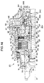
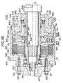
- the diametrically smaller cylindrical portion 9 is arranged in an opening 8 of the cover 6, and the outer end portion of the cover 6 in the diametrically smaller cylindrical portion 9 is closed by the bottom portion 10.
- the annular joint portion 11 is extended to the outer circumferential side from the inner side end portion of the cover 6 in the diametrically smaller cylindrical portion 9.
- the diametrically larger cylindrical portion 12 is arranged toward the inner side of the differential carrier 1 from the outer circumferential end of the joint portion 11.
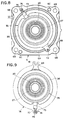
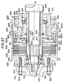
- the cylindrical portion 15 of the differential carrier 1 there are formed a plurality of grooves 45 which are positioned to correspond to the ridges 44.
- the cylindrical portion 40 of the iron core 36 is arranged in the cylindrical portion 15 of the differential carrier 1 so that the ridges 44 are individually fitted in the grooves 45.
- the ridges 44 and the grooves 45 may be individually provided by at least one.
- These cylindrical portion 15, ridges 44 and grooves 45 are arranged to face an opening 6A of the cover 6 and an opening 1A of the differential carrier 1.
- a groove 14M In the end face 14 of the differential carrier 1 at the side of the cover 6, there is formed a groove 14M, along which the electric wire 38 is arranged.
- This electric wire 38 is guided through a through groove 47, as formed in the abutting faces of the differential carrier 1 and the cover 6, to the outside of the differential carrier 1 and the cover 6 to be connected with a not-shown power source.
- An annular shim 48 is fitted on the outer circumference of the cylindrical portion 15 of the differential carrier 1, and the seal bearing 16 is made to abut against the end face of the shim 48.
- the electric wire 38, as threaded in the groove 14 is held by the shim 48 so that it is fixed.
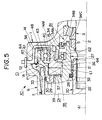
- a cylindrical portion 65 on the axis A1 is formed in the iron core 36 of the electromagnet 35, and the (radial) bearing 41 is fitted between the cylindrical portion 65 and the rotor 27. Moreover, the electromagnet 35 and the rotor 27 are positioned in the direction of the axis A1 by the bearing 41, the snap ring 42 fitted on the inner cylindrical portion 28, and the snap ring 43 fitted on the iron core 36.
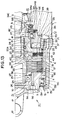
- This second assembling example is also applied to the case in which the construction of the differential carrier 1 is slightly different from that of the embodiment of Figs. 6 and 7.
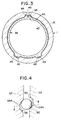
- grooved portions 1B and 1C are formed to protrude outward in the generally circular opening 1A of the differential carrier 1.
- These grooved portions 1B and 1C are arranged at a spacing of about 180 degrees with respect to the circumferential direction of the opening 1A.
- the protrusion 69 is arranged in the grooved portion 1B, and the electric wire 74 is arranged in the grooved portion 1C.
- the electric wire 74, the protrusion 69 and the grooved portions 1B and 1C correspond to the positioning mechanism of the invention.
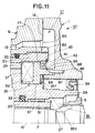
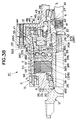
- the connector 94 is fitted on the joint portion 89.
- the mere fitting of the joint portion 89 in the fitting hole 92 makes it possible to handle the connector 94 with respect to the differential carrier 1, to stop the rotation of the electromagnet 35 with respect to the differential carrier 1 and to end the sealing of the outer circumference of the joint portion 89.
- the assembling workability of the driving force transmission system K1 is improved to reduce the number of steps of assembling the driving force transmission system K1.
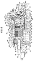
- the shaft 20 is formed into a cylindrical shape, and the drive pinion shaft 2 is splined in the inner circumference of the one end of the shaft 20.
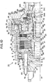
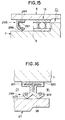
- the coupling case 7 In the end portion of the coupling case 7 at the side of the flange 17, on the other hand, there is formed an opening 97, in which a blind cover 98 is fitted.
- an X-ring 99 In the inner circumference of the diametrically smaller cylindrical portion 9 of the coupling case 7, moreover, there is fitted an X-ring 99, by which the coupling case 7 and the shaft 20 are sealed liquid-fight.
- a hole 304 which is opened in the outer end face of the cylindrical portion 9.
- the hole 304 is internally threaded at 9c in its inner circumference.
- the hole 304 is arranged to have a (not-shown) axis in parallel with the axis A1, and the embedded side externally threaded portion 79 is driven into the internally threaded portion 9C.
- an incompletely threaded portion 305 of the embedded side externally threaded portion 79 is brought into abutment against the internally threaded portion 9C thereby to position the stud bolt 78 and the diametrically smaller cylindrical portion 9 in the axial direction.
- a magnetic path is established among the cover member 218, the individual clutch plates 236, the clutch discs 235 and the armature 237 by energizing the electromagnetic coil 238. Then, the armature 237 is attracted toward the electromagnetic coil 238 by the magnetic induction. As a result, the armature 237 pushes the clutch disc 235 and the clutch plates 236 toward the cover member 218. As a result, the clutch disc 235 and the clutch plates 236 are brought into frictional engagement with each other.
- the frictional applying force for the pilot clutch mechanism 215 rises in proportion to the current value which is fed to the electromagnetic coil 238.
- the pushing force to be generated in the cam mechanism 216 increases, and the frictional applying force for the main clutch mechanism 214 increases so that the torque to be transmitted from the outer housing 212 to the main shaft 213 gradually rises.
- the pilot clutch 49 is equipped with the three clutch plates 54 and the four clutch discs (or plates) 52.
- one clutch disc 52 confronts the armature 51
- one clutch disc 52 confronts the rotor 27.
- the rotor 27 corresponds to the magnetic path forming member, and the oil seal 34 corresponds to the other member. Moreover, the rotor 27 corresponds to the side wall of the invention.
- the clutch mechanism 325 is of the multi-disc type including a plurality of clutch discs 338 and a plurality of clutch plates 339.
- Each clutch disc 338 is fitted at its inner circumference in the spline which is formed in the outer circumference of the intermediate portion of the shaft 324, and is so assembled that it can rotate integrally with the shaft 324 and move in the axial direction.
- each clutch plate 339 is fitted at its outer circumference in the spline which is formed in the inner circumference of the coupling case 323, and is so assembled that it can rotate integrally with the coupling case 323 and move in the axial direction.
- the individual clutch discs 338 and the individual clutch plates 339 are alternately positioned at the side of the inward flange 340 of the coupling case 323 and are brought into abutment against each other to come into frictional engagement and out of abutment to take free states.
- the second cam mechanism 328 is composed of a first cam member 352 a second can, member 353 and cam followers 354. Moreover, the first cam member 352 acts as the second cam member 349 constructing the first cam mechanism 327.
- the second cam member 353 is fitted in the spline which is formed in the inner circumference of the coupling case 323, and can rotate integrally with with coupling case 323 and can move in the axial direction.
- a stud bolt is constructed to have an embedded side externally threaded portion to be embedded in the internally threaded portion of the first rotary member, and a nut-side externally threaded portion to be screwed in the internally threaded portion of the nut, wherein the external diameter of the embedded side externally threaded portion and the external diameter of the nut-side externally threaded portion are set on the basis of the strength of the first rotary member and the strength of the stud bolt.
- the external diameter of the embedded side externally threaded portion and the external diameter of the nut-side externally threaded portion could also be set on the basis of the strength of the nut and the strength of the stud bolt.
Priority Applications (1)
| Application Number | Priority Date | Filing Date | Title |
|---|---|---|---|
| EP02023531A EP1277982B1 (de) | 1997-01-29 | 1998-01-28 | Antriebskraftübertragungssystem |
Applications Claiming Priority (39)
| Application Number | Priority Date | Filing Date | Title |
|---|---|---|---|
| JP1567097 | 1997-01-29 | ||
| JP15670/97 | 1997-01-29 | ||
| JP1567097 | 1997-01-29 | ||
| JP16934/97 | 1997-01-30 | ||
| JP1693497 | 1997-01-30 | ||
| JP09016934A JP3128523B2 (ja) | 1997-01-30 | 1997-01-30 | 駆動力伝達装置 |
| JP4987597 | 1997-02-18 | ||
| JP49876/97 | 1997-02-18 | ||
| JP4987797 | 1997-02-18 | ||
| JP04987797A JP3442250B2 (ja) | 1997-02-18 | 1997-02-18 | 駆動力伝達装置 |
| JP4987697 | 1997-02-18 | ||
| JP49877/97 | 1997-02-18 | ||
| JP4987697 | 1997-02-18 | ||
| JP4987597 | 1997-02-18 | ||
| JP49875/97 | 1997-02-18 | ||
| JP32151997 | 1997-11-21 | ||
| JP337750/97 | 1997-11-21 | ||
| JP337749/97 | 1997-11-21 | ||
| JP33775197 | 1997-11-21 | ||
| JP33774897 | 1997-11-21 | ||
| JP32151997A JP3243438B2 (ja) | 1997-11-21 | 1997-11-21 | 駆動力伝達装置 |
| JP321519/97 | 1997-11-21 | ||
| JP33775197A JP3618209B2 (ja) | 1997-02-18 | 1997-11-21 | 駆動力伝達装置 |
| JP337751/97 | 1997-11-21 | ||
| JP32150297 | 1997-11-21 | ||
| JP32150297A JP3256737B2 (ja) | 1997-11-21 | 1997-11-21 | 駆動力伝達装置 |
| JP321502/97 | 1997-11-21 | ||
| JP33775097 | 1997-11-21 | ||
| JP337748/97 | 1997-11-21 | ||
| JP33774897A JPH11153116A (ja) | 1997-11-21 | 1997-11-21 | 植込みボルト |
| JP321513/97 | 1997-11-21 | ||
| JP32151597A JP3456887B2 (ja) | 1997-11-21 | 1997-11-21 | 駆動力伝達装置 |
| JP321515/97 | 1997-11-21 | ||
| JP32151397 | 1997-11-21 | ||
| JP33774997 | 1997-11-21 | ||
| JP9337750A JPH10292827A (ja) | 1997-02-18 | 1997-11-21 | 駆動力伝達装置 |
| JP32151597 | 1997-11-21 | ||
| JP33774997A JP3619648B2 (ja) | 1997-01-29 | 1997-11-21 | 駆動力伝達装置 |
| JP32151397A JP3243437B2 (ja) | 1997-11-21 | 1997-11-21 | 駆動力伝達装置 |
Related Child Applications (1)
| Application Number | Title | Priority Date | Filing Date |
|---|---|---|---|
| EP02023531A Division EP1277982B1 (de) | 1997-01-29 | 1998-01-28 | Antriebskraftübertragungssystem |
Publications (3)
| Publication Number | Publication Date |
|---|---|
| EP0856676A1 true EP0856676A1 (de) | 1998-08-05 |
| EP0856676B1 EP0856676B1 (de) | 2004-07-28 |
| EP0856676B8 EP0856676B8 (de) | 2005-01-12 |
Family
ID=27584145
Family Applications (2)
| Application Number | Title | Priority Date | Filing Date |
|---|---|---|---|
| EP98101491A Expired - Lifetime EP0856676B8 (de) | 1997-01-29 | 1998-01-28 | Kupplungseinheit |
| EP02023531A Expired - Lifetime EP1277982B1 (de) | 1997-01-29 | 1998-01-28 | Antriebskraftübertragungssystem |
Family Applications After (1)
| Application Number | Title | Priority Date | Filing Date |
|---|---|---|---|
| EP02023531A Expired - Lifetime EP1277982B1 (de) | 1997-01-29 | 1998-01-28 | Antriebskraftübertragungssystem |
Country Status (2)
| Country | Link |
|---|---|
| US (3) | US6109408A (de) |
| EP (2) | EP0856676B8 (de) |
Cited By (18)
| Publication number | Priority date | Publication date | Assignee | Title |
|---|---|---|---|---|
| EP0947720A2 (de) * | 1998-04-01 | 1999-10-06 | Toyoda Koki Kabushiki Kaisha | Kupplungsscheibe |
| EP1031749A1 (de) * | 1999-02-22 | 2000-08-30 | Toyoda Koki Kabushiki Kaisha | Elektromagnetische Kupplung und Antriebsübertragungseinheit unter Verwendung derselben |
| FR2792693A1 (fr) * | 1999-04-23 | 2000-10-27 | Gkn Viscodrive Gmbh | Visco-accouplement commande et procede de commande pour celui-ci |
| EP1178233A2 (de) * | 2000-08-01 | 2002-02-06 | Toyoda Koki Kabushiki Kaisha | Antriebskraft-Übertragungseinrichtung |
| WO2002018810A1 (fr) * | 2000-08-31 | 2002-03-07 | Toyoda Koki Kabushiki Kaisha | Dispositif de transmission de force de courant d'attaque et procede de regulation de cette force |
| EP1221393A1 (de) * | 2000-12-27 | 2002-07-10 | Tochigi Fuji Sangyo Kabushiki Kaisha | Anordnung und Verfahren eine elektromagnetische Kupplung zu unterstützen |
| EP1227259A2 (de) * | 2001-01-24 | 2002-07-31 | Toyoda Koki Kabushiki Kaisha | Antriebskraft-Übertragungseinrichtung |
| EP1288519A1 (de) * | 2001-08-31 | 2003-03-05 | Toyoda Koki Kabushiki Kaisha | Vorrichtung mit servogesteuerten elektromagnetischen Kupplung |
| WO2003019027A1 (fr) * | 2001-08-27 | 2003-03-06 | Toyoda Koki Kabushiki Kaisha | Dispositif de transmission de puissance |
| EP1279547A3 (de) * | 2001-07-25 | 2004-04-14 | JATCO Ltd | Halbautomatisches Getriebe |
| US6920968B2 (en) | 2001-12-25 | 2005-07-26 | Toyoda Koki Kabushiki Kaisha | Clutch plate, friction clutch, and coupling device |
| EP1903237A1 (de) * | 2006-09-20 | 2008-03-26 | Jtekt Corporation | Kraftübertragungsvorrichtung |
| EP1906041A2 (de) * | 2006-09-26 | 2008-04-02 | Jtekt Corporation | Kraftübertragungsvorrichtung |
| EP1927498A1 (de) * | 2006-12-01 | 2008-06-04 | GKN Driveline International GmbH | Antriebsanordnung mit Zwischenwelle und Kupplungseinheit |
| US7815028B2 (en) | 2002-05-24 | 2010-10-19 | Jtekt Corporation | Clutch plate, friction clutch, and coupling device |
| CN102889314A (zh) * | 2011-07-21 | 2013-01-23 | 舍弗勒技术股份两合公司 | 湿式离合器 |
| CN107614916A (zh) * | 2015-04-21 | 2018-01-19 | 埃索欧耐迪克超动力 | 具有圆柱形流体间隙的磁流变流体离合器设备 |
| EP3412934A4 (de) * | 2016-09-28 | 2019-08-28 | Komatsu Ltd. | Leistungsübertragungsvorrichtung |
Families Citing this family (44)
| Publication number | Priority date | Publication date | Assignee | Title |
|---|---|---|---|---|
| EP0856676B8 (de) * | 1997-01-29 | 2005-01-12 | Toyota Jidosha Kabushiki Kaisha | Kupplungseinheit |
| JP3746384B2 (ja) * | 1998-11-20 | 2006-02-15 | トヨタ自動車株式会社 | 車両用駆動力伝達制御装置 |
| US6098770A (en) * | 1999-03-19 | 2000-08-08 | Borgwarner Inc. | Clutch assembly having reaction force circuit |
| JP2000280772A (ja) * | 1999-03-30 | 2000-10-10 | Suzuki Motor Corp | 4wd車のトランスファ取付構造 |
| US6302251B1 (en) * | 2000-03-02 | 2001-10-16 | Borgwarner Inc. | Electromagnetic clutch with asymmetric spoke patterns |
| US6561332B2 (en) | 2000-04-17 | 2003-05-13 | Eaton Corporation | Ball ramp clutch with frictional damping |
| JP2002195384A (ja) * | 2000-10-19 | 2002-07-10 | Tochigi Fuji Ind Co Ltd | デファレンシャル装置 |
| JP3848835B2 (ja) * | 2000-12-25 | 2006-11-22 | 株式会社ジェイテクト | 駆動力伝達装置 |
| US6381530B1 (en) * | 2001-02-06 | 2002-04-30 | Borgwarner Inc. | Transfer case having temperature compensation |
| US6460674B1 (en) | 2001-03-22 | 2002-10-08 | Borgwarner, Inc. | Clutch face finish and clutch pack utilizing same |
| US6719110B2 (en) * | 2001-07-05 | 2004-04-13 | Tochigi Fuji Sangyo Kabushiki Kaisha | Wet type friction clutch and electromagnetic clutch |
| JP2003039969A (ja) * | 2001-07-26 | 2003-02-13 | Showa Corp | 動力伝達装置 |
| JP2003039968A (ja) * | 2001-07-26 | 2003-02-13 | Showa Corp | 動力伝達装置 |
| US6637569B1 (en) | 2002-05-09 | 2003-10-28 | Eaton Corporation | Ball ramp actuator with indexing plates |
| US6666315B2 (en) | 2002-05-09 | 2003-12-23 | Eaton Corporation | Ball ramp clutch with indexing plates |
| US6675943B2 (en) | 2002-05-09 | 2004-01-13 | Eaton Corporation | Lubrication system for ball ramp clutch systems |
| US6837351B2 (en) * | 2002-05-29 | 2005-01-04 | Borgwarner, Inc. | Electromagnetic clutch assembly having enhanced torque throughput |
| US7063193B2 (en) * | 2002-09-25 | 2006-06-20 | Tochigi Fuji Sangyo Kabushiki Kaisha | Seal structure for relatively rotational members |
| US6997294B2 (en) * | 2002-12-10 | 2006-02-14 | Tochigi Fuji Sangyo Kabushiki Kaisha | Electromagnetic clutch device |
| JP2004340317A (ja) * | 2003-05-19 | 2004-12-02 | Toyoda Mach Works Ltd | 電磁クラッチおよび電磁クラッチの磁路形成部材の製造方法 |
| US6905008B2 (en) * | 2003-08-11 | 2005-06-14 | Borgwarner, Inc. | Electromagnetic clutch assembly having solenoid type operator |
| JP2005133740A (ja) * | 2003-10-28 | 2005-05-26 | Jatco Ltd | 電磁多板クラッチ |
| DE10356307A1 (de) * | 2003-11-28 | 2005-06-23 | Robert Bosch Gmbh | Verfahren und Vorrichtung zur Warnung des Fahrers eines Kraftfahrzeugs |
| KR100620824B1 (ko) * | 2004-08-12 | 2006-09-19 | 현대자동차주식회사 | 커플링 |
| US7338403B2 (en) * | 2004-08-30 | 2008-03-04 | Magna Powertrain Usa, Inc. | Torque coupling with power-operated clutch actuator |
| DE102005041080A1 (de) * | 2004-08-31 | 2006-03-16 | Tochigi Fuji Sangyo K.K. | Reibeingriffsvorrichtung |
| US7581628B2 (en) * | 2005-06-22 | 2009-09-01 | Gkn Driveline Torque Technology Kk | Electromagnetic clutch |
| JP4676294B2 (ja) * | 2005-09-30 | 2011-04-27 | 本田技研工業株式会社 | 動力伝達構造 |
| JP4650225B2 (ja) * | 2005-11-15 | 2011-03-16 | 株式会社ジェイテクト | 駆動力伝達装置 |
| JP2008057733A (ja) * | 2006-09-01 | 2008-03-13 | Minebea Co Ltd | 電磁クラッチ |
| US7837585B2 (en) * | 2006-11-27 | 2010-11-23 | American Axle & Manufacturing, Inc. | Linear actuator with position sensing system |
| JP2009019743A (ja) * | 2007-07-13 | 2009-01-29 | Gkn ドライブライン トルクテクノロジー株式会社 | 動力伝達装置 |
| WO2009023414A1 (en) * | 2007-08-13 | 2009-02-19 | Borgwarner Inc. | Torque feedback sensor |
| US20110061983A1 (en) * | 2008-06-04 | 2011-03-17 | Takanobu Sato | Rotation transmission device |
| TW201200766A (en) * | 2010-06-22 | 2012-01-01 | Plastics Industry Dev Ct | Pressure resistant oil seal |
| JP5668398B2 (ja) * | 2010-08-30 | 2015-02-12 | 株式会社ジェイテクト | 駆動力伝達装置及び車両 |
| DE102010045721A1 (de) * | 2010-09-16 | 2012-03-22 | Magna Powertrain Ag & Co. Kg | Drehmomentübertragungseinrichtung |
| JP5658046B2 (ja) | 2011-01-21 | 2015-01-21 | Ntn株式会社 | 回転伝達装置 |
| JP5685112B2 (ja) | 2011-03-07 | 2015-03-18 | Ntn株式会社 | 電気自動車用駆動装置 |
| US9221336B1 (en) * | 2011-11-14 | 2015-12-29 | Hydro-Gear Limited Partnership | Integral power distribution assembly for engine |
| JP5974711B2 (ja) | 2012-07-31 | 2016-08-23 | 株式会社ジェイテクト | 駆動力伝達装置の製造方法 |
| CN102935572B (zh) * | 2012-12-04 | 2014-11-05 | 贵州天义电器有限责任公司 | 一种电磁驱动组件焊接定位夹具 |
| CN108730363A (zh) * | 2018-06-26 | 2018-11-02 | 江苏名豪汽车零部件有限公司 | 一种散热效果好的高性能离合器 |
| US10808830B2 (en) * | 2018-11-30 | 2020-10-20 | Arvinmeritor Technology, Llc | Axle assembly with multiple lubricant chambers |
Citations (10)
| Publication number | Priority date | Publication date | Assignee | Title |
|---|---|---|---|---|
| US2989161A (en) * | 1955-11-25 | 1961-06-20 | Ite Circuit Breaker Ltd | Electromagnetic clutch with stationary coil |
| US3037601A (en) * | 1956-08-10 | 1962-06-05 | Wilhelm Binder K G | Electro-magnetic clutch |
| FR2004904A1 (de) * | 1968-03-28 | 1969-12-05 | Pittler Ag Maschf | |
| EP0105686A2 (de) * | 1982-09-30 | 1984-04-18 | AlliedSignal Inc. | Lader |
| WO1988009447A1 (en) * | 1987-05-27 | 1988-12-01 | Zahnradfabrik Friedrichshafen Ag | Drive for fan rotor |
| JPH01145431A (ja) * | 1987-11-30 | 1989-06-07 | Taiho Kogyo Co Ltd | 湿式クラッチ装置 |
| US4958712A (en) * | 1987-06-29 | 1990-09-25 | Taiho Kogyo Co. Ltd. | Wet clutch device |
| JPH03219123A (ja) | 1989-07-20 | 1991-09-26 | Tochigi Fuji Ind Co Ltd | 連結装置 |
| JPH03282019A (ja) | 1990-03-28 | 1991-12-12 | Tochigi Fuji Ind Co Ltd | 連結装置 |
| DE19730714A1 (de) * | 1996-07-17 | 1998-01-22 | Toyoda Machine Works Ltd | Kraftübertragungsvorrichtung |
Family Cites Families (39)
| Publication number | Priority date | Publication date | Assignee | Title |
|---|---|---|---|---|
| US3053364A (en) | 1956-10-24 | 1962-09-11 | Ite Circuit Breaker Ltd | Electromagnetic claw clutches |
| BE792986A (fr) | 1971-12-20 | 1973-06-19 | Caterpillar Tractor Co | Agencement de joint double |
| JPS5740521B2 (de) | 1973-06-20 | 1982-08-28 | ||
| JPS5555614A (en) | 1978-10-20 | 1980-04-23 | Toshiba Corp | Surface acoustic wave device |
| US4320723A (en) * | 1979-06-11 | 1982-03-23 | Wendling Vincent F | Selectively operable fan drive arrangement |
| US4682676A (en) | 1984-10-26 | 1987-07-28 | Toyota Jidosha Kabushiki Kaisha | Electromagnetic powder clutch with two powder gaps |
| JPS61184112A (ja) | 1985-02-13 | 1986-08-16 | Toyota Motor Corp | 車両制御装置 |
| JPS6389414A (ja) | 1986-10-03 | 1988-04-20 | Mitsubishi Metal Corp | クロロポリシランの製造方法 |
| US4718303A (en) * | 1986-10-06 | 1988-01-12 | Borg-Warner Automotive, Inc. | Four wheel drive transfer case with clutch mechanism |
| JPH0668392B2 (ja) | 1987-07-09 | 1994-08-31 | 高砂熱学工業株式会社 | 空気調和システム |
| JPH01145438A (ja) | 1987-11-30 | 1989-06-07 | Taiho Kogyo Co Ltd | 湿式クラッチ装置 |
| JP2548311B2 (ja) * | 1988-07-08 | 1996-10-30 | 沖電気工業株式会社 | 光磁気記録媒体及びその製造方法 |
| US5005397A (en) * | 1988-08-09 | 1991-04-09 | The National Machinery Company | Method for providing progressive formers with quick-change tooling |
| JPH02286943A (ja) | 1989-04-28 | 1990-11-27 | Tochigi Fuji Ind Co Ltd | 動力伝達装置 |
| US5083986A (en) | 1989-07-20 | 1992-01-28 | Tochigifujisangyo Kabushiki Kaisha | Coupling apparatus with double clutches |
| EP0516708B1 (de) * | 1990-02-26 | 1994-12-21 | ZF FRIEDRICHSHAFEN Aktiengesellschaft | Dichtungsanordnung |
| DE4009567A1 (de) * | 1990-03-24 | 1991-09-26 | Merck Patent Gmbh | Beschichtung mit organischen farbstoffen |
| JPH0418723A (ja) * | 1990-05-11 | 1992-01-22 | Mitsubishi Electric Corp | 半導体結晶の成長方法 |
| JP2525611Y2 (ja) | 1990-06-05 | 1997-02-12 | 栃木富士産業株式会社 | 電磁多板クラッチ |
| US5269730A (en) | 1990-06-05 | 1993-12-14 | Tochigifujisangyo Kabushiki Kaisha | Differential gear device for vehicle |
| JPH0492126A (ja) | 1990-08-06 | 1992-03-25 | Tochigi Fuji Ind Co Ltd | 動力伝導装置 |
| JPH0499433A (ja) | 1990-08-16 | 1992-03-31 | Gunji Sumiya | 潜水浮子 |
| JPH04136333A (ja) | 1990-09-26 | 1992-05-11 | Haneda Concrete Kogyo Kk | 雨水貯留浸透装置 |
| JPH04138133A (ja) * | 1990-09-28 | 1992-05-12 | Yokogawa Medical Syst Ltd | コイル位置検出方法およびmr装置 |
| JP3012345B2 (ja) | 1991-01-17 | 2000-02-21 | 東燃株式会社 | 5−(2,4−ジオキソテトラヒドロ−3− フラニルメチル)ノルボルナン−2,3− ジカルボン酸無水物及びその製造法 |
| JPH0512763A (ja) | 1991-07-02 | 1993-01-22 | Sony Corp | テープテンシヨン調整機構 |
| JP3077280B2 (ja) | 1991-08-07 | 2000-08-14 | 松下電器産業株式会社 | 着磁装置およびそれを用いた永久磁石の着磁方法 |
| JP3002040B2 (ja) | 1991-11-19 | 2000-01-24 | 栃木富士産業株式会社 | デファレンシャル装置 |
| JP3259307B2 (ja) | 1992-01-17 | 2002-02-25 | 株式会社ニコン | 撮影装置 |
| JPH05193384A (ja) | 1992-01-22 | 1993-08-03 | Tochigi Fuji Ind Co Ltd | 動力伝達装置 |
| JP2747165B2 (ja) * | 1992-05-06 | 1998-05-06 | 栃木富士産業株式会社 | デファレンシャル装置 |
| JP3187542B2 (ja) | 1992-07-14 | 2001-07-11 | 経済産業省産業技術総合研究所長 | 芳香族ジカルボン酸ジエステルの製造方法 |
| JP3344490B2 (ja) | 1992-08-04 | 2002-11-11 | 中部電力株式会社 | 多段ポンプ水車 |
| JPH0714229A (ja) * | 1993-04-30 | 1995-01-17 | Sony Corp | 光磁気記録媒体及びその製造方法 |
| FR2706565B1 (fr) * | 1993-06-14 | 1995-09-01 | Piv Sa | Joint d'étanchéité pour arbre tournant. |
| JP3086569B2 (ja) * | 1993-06-30 | 2000-09-11 | 栃木富士産業株式会社 | デファレンシャル装置 |
| JPH07186763A (ja) | 1993-12-28 | 1995-07-25 | Tochigi Fuji Ind Co Ltd | トランスファー |
| EP0856676B8 (de) * | 1997-01-29 | 2005-01-12 | Toyota Jidosha Kabushiki Kaisha | Kupplungseinheit |
| US5848678A (en) | 1997-06-04 | 1998-12-15 | General Motors Corporation | Passive magnetorheological clutch |
-
1998
- 1998-01-28 EP EP98101491A patent/EP0856676B8/de not_active Expired - Lifetime
- 1998-01-28 US US09/014,627 patent/US6109408A/en not_active Expired - Lifetime
- 1998-01-28 EP EP02023531A patent/EP1277982B1/de not_active Expired - Lifetime
-
2000
- 2000-01-12 US US09/481,408 patent/US6315099B1/en not_active Expired - Lifetime
-
2001
- 2001-11-13 US US09/986,964 patent/US6510932B2/en not_active Expired - Lifetime
Patent Citations (10)
| Publication number | Priority date | Publication date | Assignee | Title |
|---|---|---|---|---|
| US2989161A (en) * | 1955-11-25 | 1961-06-20 | Ite Circuit Breaker Ltd | Electromagnetic clutch with stationary coil |
| US3037601A (en) * | 1956-08-10 | 1962-06-05 | Wilhelm Binder K G | Electro-magnetic clutch |
| FR2004904A1 (de) * | 1968-03-28 | 1969-12-05 | Pittler Ag Maschf | |
| EP0105686A2 (de) * | 1982-09-30 | 1984-04-18 | AlliedSignal Inc. | Lader |
| WO1988009447A1 (en) * | 1987-05-27 | 1988-12-01 | Zahnradfabrik Friedrichshafen Ag | Drive for fan rotor |
| US4958712A (en) * | 1987-06-29 | 1990-09-25 | Taiho Kogyo Co. Ltd. | Wet clutch device |
| JPH01145431A (ja) * | 1987-11-30 | 1989-06-07 | Taiho Kogyo Co Ltd | 湿式クラッチ装置 |
| JPH03219123A (ja) | 1989-07-20 | 1991-09-26 | Tochigi Fuji Ind Co Ltd | 連結装置 |
| JPH03282019A (ja) | 1990-03-28 | 1991-12-12 | Tochigi Fuji Ind Co Ltd | 連結装置 |
| DE19730714A1 (de) * | 1996-07-17 | 1998-01-22 | Toyoda Machine Works Ltd | Kraftübertragungsvorrichtung |
Non-Patent Citations (2)
| Title |
|---|
| PATENT ABSTRACTS OF JAPAN vol. 13, no. 400 (M - 867) 6 September 1989 (1989-09-06) * |
| PATENT ABSTRACTS OF JAPAN vol. 16, no. 115 (M - 1224) 23 March 1992 (1992-03-23) * |
Cited By (34)
| Publication number | Priority date | Publication date | Assignee | Title |
|---|---|---|---|---|
| EP0947720A3 (de) * | 1998-04-01 | 2002-09-11 | Toyoda Koki Kabushiki Kaisha | Kupplungsscheibe |
| EP0947720A2 (de) * | 1998-04-01 | 1999-10-06 | Toyoda Koki Kabushiki Kaisha | Kupplungsscheibe |
| EP1031749A1 (de) * | 1999-02-22 | 2000-08-30 | Toyoda Koki Kabushiki Kaisha | Elektromagnetische Kupplung und Antriebsübertragungseinheit unter Verwendung derselben |
| FR2792693A1 (fr) * | 1999-04-23 | 2000-10-27 | Gkn Viscodrive Gmbh | Visco-accouplement commande et procede de commande pour celui-ci |
| EP1178233A2 (de) * | 2000-08-01 | 2002-02-06 | Toyoda Koki Kabushiki Kaisha | Antriebskraft-Übertragungseinrichtung |
| EP1178233A3 (de) * | 2000-08-01 | 2003-10-15 | Toyoda Koki Kabushiki Kaisha | Antriebskraft-Übertragungseinrichtung |
| WO2002018810A1 (fr) * | 2000-08-31 | 2002-03-07 | Toyoda Koki Kabushiki Kaisha | Dispositif de transmission de force de courant d'attaque et procede de regulation de cette force |
| US6851535B2 (en) | 2000-08-31 | 2005-02-08 | Toyoda Koki Kabushiki Kaisha | Driving force transmission device and method of regulating it |
| EP1221393A1 (de) * | 2000-12-27 | 2002-07-10 | Tochigi Fuji Sangyo Kabushiki Kaisha | Anordnung und Verfahren eine elektromagnetische Kupplung zu unterstützen |
| US6729455B2 (en) | 2000-12-27 | 2004-05-04 | Tochigi Fuji Sangyo Kabushiki Kaisha | Structure and method for supporting electromagnetic coupling |
| EP1227259A2 (de) * | 2001-01-24 | 2002-07-31 | Toyoda Koki Kabushiki Kaisha | Antriebskraft-Übertragungseinrichtung |
| EP1227259A3 (de) * | 2001-01-24 | 2003-10-15 | Toyoda Koki Kabushiki Kaisha | Antriebskraft-Übertragungseinrichtung |
| EP1279547A3 (de) * | 2001-07-25 | 2004-04-14 | JATCO Ltd | Halbautomatisches Getriebe |
| WO2003019027A1 (fr) * | 2001-08-27 | 2003-03-06 | Toyoda Koki Kabushiki Kaisha | Dispositif de transmission de puissance |
| EP1288519A1 (de) * | 2001-08-31 | 2003-03-05 | Toyoda Koki Kabushiki Kaisha | Vorrichtung mit servogesteuerten elektromagnetischen Kupplung |
| US6622838B2 (en) | 2001-08-31 | 2003-09-23 | Toyoda Koki Kabushiki Kaisha | Electromagnetic pilot-type clutch device |
| US6920968B2 (en) | 2001-12-25 | 2005-07-26 | Toyoda Koki Kabushiki Kaisha | Clutch plate, friction clutch, and coupling device |
| EP1571365A1 (de) * | 2001-12-25 | 2005-09-07 | Toyoda Koki Kabushiki Kaisha | Kupplungsscheibe, Reibungskupplung und Kupplungsvorrichtung |
| EP1870611A1 (de) * | 2001-12-25 | 2007-12-26 | Jtekt Corporation | Kupplungsscheibe, Reibkupplung und Kopplungsvorrichtung |
| EP1323942B1 (de) * | 2001-12-25 | 2005-08-10 | Toyoda Koki Kabushiki Kaisha | Kupplungsscheibe, Reibungskupplung und Kupplungsvorrichtung |
| US7815028B2 (en) | 2002-05-24 | 2010-10-19 | Jtekt Corporation | Clutch plate, friction clutch, and coupling device |
| US7849988B2 (en) | 2006-09-20 | 2010-12-14 | Jtekt Corporation | Power transmitting device |
| EP1903237A1 (de) * | 2006-09-20 | 2008-03-26 | Jtekt Corporation | Kraftübertragungsvorrichtung |
| EP1906041A2 (de) * | 2006-09-26 | 2008-04-02 | Jtekt Corporation | Kraftübertragungsvorrichtung |
| US8746431B2 (en) | 2006-09-26 | 2014-06-10 | Jtekt Corporation | Power transmission device |
| EP1906041A3 (de) * | 2006-09-26 | 2010-07-07 | Jtekt Corporation | Kraftübertragungsvorrichtung |
| US7846056B2 (en) | 2006-12-01 | 2010-12-07 | Gkn Driveline International Gmbh | Drive assembly with intermediate shaft and coupling unit |
| EP1927498A1 (de) * | 2006-12-01 | 2008-06-04 | GKN Driveline International GmbH | Antriebsanordnung mit Zwischenwelle und Kupplungseinheit |
| CN102889314A (zh) * | 2011-07-21 | 2013-01-23 | 舍弗勒技术股份两合公司 | 湿式离合器 |
| CN102889314B (zh) * | 2011-07-21 | 2016-08-03 | 舍弗勒技术股份两合公司 | 湿式离合器 |
| CN107614916A (zh) * | 2015-04-21 | 2018-01-19 | 埃索欧耐迪克超动力 | 具有圆柱形流体间隙的磁流变流体离合器设备 |
| CN107614916B (zh) * | 2015-04-21 | 2019-09-24 | 埃索欧耐迪克超动力 | 磁流变流体离合器设备 |
| US10480594B2 (en) | 2015-04-21 | 2019-11-19 | Exonetik Inc. | Magnetorheological fluid clutch apparatus with cylindrical fluid gap |
| EP3412934A4 (de) * | 2016-09-28 | 2019-08-28 | Komatsu Ltd. | Leistungsübertragungsvorrichtung |
Also Published As
| Publication number | Publication date |
|---|---|
| EP1277982B1 (de) | 2005-12-28 |
| US6109408A (en) | 2000-08-29 |
| US6510932B2 (en) | 2003-01-28 |
| EP0856676B1 (de) | 2004-07-28 |
| EP1277982A3 (de) | 2004-06-23 |
| EP0856676B8 (de) | 2005-01-12 |
| US6315099B1 (en) | 2001-11-13 |
| EP1277982A2 (de) | 2003-01-22 |
| US20020027056A1 (en) | 2002-03-07 |
Similar Documents
| Publication | Publication Date | Title |
|---|---|---|
| EP1277982B1 (de) | Antriebskraftübertragungssystem | |
| EP2507533B1 (de) | Anschlussanordnung und herstellungsverfahren für eine anschlussanordnung | |
| WO2013069595A1 (ja) | 駆動力伝達装置 | |
| JPWO2015056330A1 (ja) | 摩擦ロスを低減したクラッチ装置およびデファレンシャル装置 | |
| US8746431B2 (en) | Power transmission device | |
| US7581628B2 (en) | Electromagnetic clutch | |
| JP2006308093A (ja) | 機械式クラッチユニット | |
| US10968999B2 (en) | Differential device for 4-wheel-drive vehicle | |
| JP4904649B2 (ja) | 電磁パイロット式クラッチ装置 | |
| JP3619648B2 (ja) | 駆動力伝達装置 | |
| JPS608568A (ja) | 粘性流体継手 | |
| EP2014945B1 (de) | Kraftübertragungsvorrichtung | |
| JP2007064465A (ja) | 回転伝達装置 | |
| JP4141430B2 (ja) | 駆動力伝達装置 | |
| JPH10292827A (ja) | 駆動力伝達装置 | |
| US8276724B2 (en) | Power transmission system for vehicle changing power transmission state by electric control | |
| CN111795080A (zh) | 包括改进的密封的湿式离合机构 | |
| JP3618209B2 (ja) | 駆動力伝達装置 | |
| JP6247519B2 (ja) | 断続装置 | |
| JP3442250B2 (ja) | 駆動力伝達装置 | |
| WO2023021707A1 (ja) | シール構造 | |
| JP2002195294A (ja) | カップリング装置 | |
| JPH11153116A (ja) | 植込みボルト | |
| JP2002195295A (ja) | カップリング装置 | |
| JP2010116966A (ja) | 駆動力配分装置 |
Legal Events
| Date | Code | Title | Description |
|---|---|---|---|
| PUAI | Public reference made under article 153(3) epc to a published international application that has entered the european phase |
Free format text: ORIGINAL CODE: 0009012 |
|
| 17P | Request for examination filed |
Effective date: 19980128 |
|
| AK | Designated contracting states |
Kind code of ref document: A1 Designated state(s): DE FR GB |
|
| AX | Request for extension of the european patent |
Free format text: AL;LT;LV;MK;RO;SI |
|
| AKX | Designation fees paid |
Free format text: DE FR GB |
|
| RBV | Designated contracting states (corrected) |
Designated state(s): DE FR GB |
|
| 17Q | First examination report despatched |
Effective date: 20010504 |
|
| GRAP | Despatch of communication of intention to grant a patent |
Free format text: ORIGINAL CODE: EPIDOSNIGR1 |
|
| GRAS | Grant fee paid |
Free format text: ORIGINAL CODE: EPIDOSNIGR3 |
|
| GRAA | (expected) grant |
Free format text: ORIGINAL CODE: 0009210 |
|
| AK | Designated contracting states |
Kind code of ref document: B1 Designated state(s): DE FR GB |
|
| REG | Reference to a national code |
Ref country code: GB Ref legal event code: FG4D |
|
| REF | Corresponds to: |
Ref document number: 69825191 Country of ref document: DE Date of ref document: 20040902 Kind code of ref document: P |
|
| RIN2 | Information on inventor provided after grant (corrected) |
Inventor name: ISOMURA, MORITAKA Inventor name: SUZUKI, AKIO Inventor name: HOSOKAWA, TAKASHI Inventor name: SAKAI, NAOYUKI Inventor name: SHIMADA, MASAYUKI Inventor name: KOKUBO, NAOYUKI Inventor name: SUZUKI, KUNIHIKO Inventor name: TAKUNO, HIROSHI Inventor name: SAKAI, TOSHIFUMI Inventor name: ASHIDA, SATOSHI Inventor name: KANO, TOMOYUKI Inventor name: ICHIKAWA, AKIHIKO Inventor name: TSUCHIYA, FUMITOMO Inventor name: OHBA, MITSURU Inventor name: SUZUKI, HIROKAZU Inventor name: OGAWA, SHINJI Inventor name: IKEDA, AKIHIKO |
|
| ET | Fr: translation filed | ||
| PLBE | No opposition filed within time limit |
Free format text: ORIGINAL CODE: 0009261 |
|
| STAA | Information on the status of an ep patent application or granted ep patent |
Free format text: STATUS: NO OPPOSITION FILED WITHIN TIME LIMIT |
|
| 26N | No opposition filed |
Effective date: 20050429 |
|
| REG | Reference to a national code |
Ref country code: FR Ref legal event code: PLFP Year of fee payment: 19 |
|
| REG | Reference to a national code |
Ref country code: FR Ref legal event code: PLFP Year of fee payment: 20 |
|
| PGFP | Annual fee paid to national office [announced via postgrant information from national office to epo] |
Ref country code: FR Payment date: 20161215 Year of fee payment: 20 |
|
| PGFP | Annual fee paid to national office [announced via postgrant information from national office to epo] |
Ref country code: DE Payment date: 20170125 Year of fee payment: 20 |
|
| PGFP | Annual fee paid to national office [announced via postgrant information from national office to epo] |
Ref country code: GB Payment date: 20170125 Year of fee payment: 20 |
|
| REG | Reference to a national code |
Ref country code: DE Ref legal event code: R071 Ref document number: 69825191 Country of ref document: DE |
|
| REG | Reference to a national code |
Ref country code: GB Ref legal event code: PE20 Expiry date: 20180127 |
|
| PG25 | Lapsed in a contracting state [announced via postgrant information from national office to epo] |
Ref country code: GB Free format text: LAPSE BECAUSE OF EXPIRATION OF PROTECTION Effective date: 20180127 |