EP0835990A2 - Moteur à combustion interne refroidi par air - Google Patents
Moteur à combustion interne refroidi par air Download PDFInfo
- Publication number
- EP0835990A2 EP0835990A2 EP97117505A EP97117505A EP0835990A2 EP 0835990 A2 EP0835990 A2 EP 0835990A2 EP 97117505 A EP97117505 A EP 97117505A EP 97117505 A EP97117505 A EP 97117505A EP 0835990 A2 EP0835990 A2 EP 0835990A2
- Authority
- EP
- European Patent Office
- Prior art keywords
- cooling fan
- cooling
- crankcase
- cooled engine
- shroud
- Prior art date
- Legal status (The legal status is an assumption and is not a legal conclusion. Google has not performed a legal analysis and makes no representation as to the accuracy of the status listed.)
- Granted
Links
Images


Classifications
-
- F—MECHANICAL ENGINEERING; LIGHTING; HEATING; WEAPONS; BLASTING
- F01—MACHINES OR ENGINES IN GENERAL; ENGINE PLANTS IN GENERAL; STEAM ENGINES
- F01P—COOLING OF MACHINES OR ENGINES IN GENERAL; COOLING OF INTERNAL-COMBUSTION ENGINES
- F01P1/00—Air cooling
- F01P1/02—Arrangements for cooling cylinders or cylinder heads, e.g. ducting cooling-air from its pressure source to cylinders or along cylinders
-
- F—MECHANICAL ENGINEERING; LIGHTING; HEATING; WEAPONS; BLASTING
- F02—COMBUSTION ENGINES; HOT-GAS OR COMBUSTION-PRODUCT ENGINE PLANTS
- F02F—CYLINDERS, PISTONS OR CASINGS, FOR COMBUSTION ENGINES; ARRANGEMENTS OF SEALINGS IN COMBUSTION ENGINES
- F02F1/00—Cylinders; Cylinder heads
- F02F1/24—Cylinder heads
- F02F1/26—Cylinder heads having cooling means
- F02F1/28—Cylinder heads having cooling means for air cooling
- F02F1/30—Finned cylinder heads
- F02F1/32—Finned cylinder heads the cylinder heads being of overhead valve type
-
- F—MECHANICAL ENGINEERING; LIGHTING; HEATING; WEAPONS; BLASTING
- F01—MACHINES OR ENGINES IN GENERAL; ENGINE PLANTS IN GENERAL; STEAM ENGINES
- F01P—COOLING OF MACHINES OR ENGINES IN GENERAL; COOLING OF INTERNAL-COMBUSTION ENGINES
- F01P5/00—Pumping cooling-air or liquid coolants
- F01P5/02—Pumping cooling-air; Arrangements of cooling-air pumps, e.g. fans or blowers
- F01P5/06—Guiding or ducting air to, or from, ducted fans
-
- F—MECHANICAL ENGINEERING; LIGHTING; HEATING; WEAPONS; BLASTING
- F02—COMBUSTION ENGINES; HOT-GAS OR COMBUSTION-PRODUCT ENGINE PLANTS
- F02B—INTERNAL-COMBUSTION PISTON ENGINES; COMBUSTION ENGINES IN GENERAL
- F02B75/00—Other engines
- F02B75/16—Engines characterised by number of cylinders, e.g. single-cylinder engines
-
- F—MECHANICAL ENGINEERING; LIGHTING; HEATING; WEAPONS; BLASTING
- F02—COMBUSTION ENGINES; HOT-GAS OR COMBUSTION-PRODUCT ENGINE PLANTS
- F02F—CYLINDERS, PISTONS OR CASINGS, FOR COMBUSTION ENGINES; ARRANGEMENTS OF SEALINGS IN COMBUSTION ENGINES
- F02F1/00—Cylinders; Cylinder heads
- F02F1/002—Integrally formed cylinders and cylinder heads
-
- F—MECHANICAL ENGINEERING; LIGHTING; HEATING; WEAPONS; BLASTING
- F01—MACHINES OR ENGINES IN GENERAL; ENGINE PLANTS IN GENERAL; STEAM ENGINES
- F01P—COOLING OF MACHINES OR ENGINES IN GENERAL; COOLING OF INTERNAL-COMBUSTION ENGINES
- F01P11/00—Component parts, details, or accessories not provided for in, or of interest apart from, groups F01P1/00 - F01P9/00
- F01P11/02—Liquid-coolant filling, overflow, venting, or draining devices
- F01P11/029—Expansion reservoirs
-
- F—MECHANICAL ENGINEERING; LIGHTING; HEATING; WEAPONS; BLASTING
- F01—MACHINES OR ENGINES IN GENERAL; ENGINE PLANTS IN GENERAL; STEAM ENGINES
- F01P—COOLING OF MACHINES OR ENGINES IN GENERAL; COOLING OF INTERNAL-COMBUSTION ENGINES
- F01P1/00—Air cooling
- F01P2001/005—Cooling engine rooms
-
- F—MECHANICAL ENGINEERING; LIGHTING; HEATING; WEAPONS; BLASTING
- F01—MACHINES OR ENGINES IN GENERAL; ENGINE PLANTS IN GENERAL; STEAM ENGINES
- F01P—COOLING OF MACHINES OR ENGINES IN GENERAL; COOLING OF INTERNAL-COMBUSTION ENGINES
- F01P1/00—Air cooling
- F01P1/02—Arrangements for cooling cylinders or cylinder heads, e.g. ducting cooling-air from its pressure source to cylinders or along cylinders
- F01P2001/023—Cooling cylinders
-
- F—MECHANICAL ENGINEERING; LIGHTING; HEATING; WEAPONS; BLASTING
- F02—COMBUSTION ENGINES; HOT-GAS OR COMBUSTION-PRODUCT ENGINE PLANTS
- F02B—INTERNAL-COMBUSTION PISTON ENGINES; COMBUSTION ENGINES IN GENERAL
- F02B75/00—Other engines
- F02B75/02—Engines characterised by their cycles, e.g. six-stroke
- F02B2075/022—Engines characterised by their cycles, e.g. six-stroke having less than six strokes per cycle
- F02B2075/027—Engines characterised by their cycles, e.g. six-stroke having less than six strokes per cycle four
-
- F—MECHANICAL ENGINEERING; LIGHTING; HEATING; WEAPONS; BLASTING
- F02—COMBUSTION ENGINES; HOT-GAS OR COMBUSTION-PRODUCT ENGINE PLANTS
- F02B—INTERNAL-COMBUSTION PISTON ENGINES; COMBUSTION ENGINES IN GENERAL
- F02B2275/00—Other engines, components or details, not provided for in other groups of this subclass
- F02B2275/34—Lateral camshaft position
Definitions
- the present invention relates to an air-cooled engine and, particularly, to an improvement in an air-cooled engine including a cooling fan mounted at one end of a crankshaft supported in a crankcase, and a shroud for guiding cooling wind produced by the cooling fan to an outer periphery of a cylinder block.
- an air-cooled engine comprising a cooling fan mounted at one end of a crankshaft supported in a crankcase, and a shroud for guiding cooling wind produced by the cooling fan to an outer periphery of a cylinder block, wherein the engine further includes an auxiliary cooling fan mounted at the other end of the crankshaft, and an auxiliary shroud for guiding cooling wind produced by the auxiliary cooling fan to an outer periphery of the crankcase.
- the absorption of a heat from the cylinder block by the crankcase can be effectively performed by cooling the crankcase by the cooling wind produced by the auxiliary cooling fan, and the effect of cooling the entire engine, including the cylinder block, can be enhanced without increasing the amount of the cooling wind flowing to the cylinder block, i.e., without increasing the diameter of the cooling fan and the size of the shroud. Therefore, the increases in size and weight of the engine can be avoided.
- an oil reservoir chamber is defined in the crankcase adjacent the auxiliary cooling fan.
- the lubricating oil in the oil reservoir chamber can be cooled satisfactorily and hence, the lubrication and cooling of the inside of the engine by the lubricating oil can be effectively performed.
- the auxiliary shroud is also formed to guide a portion of cooling wind produced by the auxiliary cooling fan to an outer periphery of a fuel tank disposed on one side of the crankcase.
- a portion of the cooling wind produced by the auxiliary cooling fan can be conducted to the region around the fuel tank and hence, the fuel in the fuel tank can also be cooled utilizing the auxiliary cooling fan.
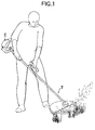
- a hand-held-type air-cooled engine E is mounted as a power source for a power trimmer T, for example, at a driving portion of the power trimmer T.
- the power trimmer T is used with a cutter which can be turned in any of various directions depending upon a working state of the power trimmer T and hence, in each case, the engine E is largely inclined or turned upside down, and the operational attitude of the engine E is not regular.
- a carburetor 2 and an exhaust muffler 3 are mounted on an engine body 1 of the air-cooler engine E at front and rear portions thereof.
- An air cleaner 4 is mounted at an inlet of an intake passage in the carburetor 2.
- a fuel tank 5 is mounted to a lower surface of the engine body 1.
- the carburetor 2 includes a diaphragm pump for pumping fuel from the fuel tank 5 by utilizing a pulsing of pressure within a crank chamber in the engine E and circulating an extra amount of fuel to the tank 5, so that the fuel can be supplied to an intake port in the engine E in any attitude of the engine E.
- the engine body 1 is comprised of a head-integral type cylinder block 6, and a crankcase 7 bonded to a lower end face of the cylinder block 6.
- the cylinder block 6 includes a single cylinder 9 with a piston 8 accommodated therein, at a center portion thereof, and has a large number of cooling fins 10 provided on an outer periphery thereof.
- crankcase 7 is comprised of a pair of upper and lower case portions 7a and 7b coupled to each other by a bolt.
- a crankshaft 12 is connected to the piston 8 through a connecting rod 11 and supported between both of the case portions 7a and 7b.
- crankcase 7 The inside of the crankcase 7 is divided into three chambers: a left oil reservoir chamber 13, a central crank chamber 14 and a right valve operating chamber 15 as shown in Fig. 2.
- a crank portion of the crankshaft 12 is disposed in the crank chamber 14, and a valve operating mechanism 17 for driving intake and exhaust valves located in a cylinder head is mounted in the valve operating chamber 15.
- a defined amount of lubricating oil O is stored in the oil reservoir chamber 13, and an oil slinger 18 for agitating the lubricating oil O to produce an oil mist is secured to the crankshaft 12.
- the oil mist produced in the oil reservoir chamber 13 is supplied to movable portions of the engine within the crank chamber 14 and the valve operating chamber 15 and is circulated to the oil reservoir chamber 13 after lubrication of the movable portions.
- a centrifugal clutch 24 is interposed between the rotor 21 and a working machine-driving shaft 23.
- a shroud designated “the first shroud” is mounted to enclose the rotor 21 and the cylinder block 6, thereby defining a cooling-air passage 26 extending from around the rotor 21 via one side of the cylinder block 6 (on the side of the valve operating chamber 15) to reach the other side (on the side of the oil reservoir chamber 13).
- the first shroud 25 has an inlet 26i and an outlet 26e communicating with the cooling-air passage 26 provided at its portion opposed to an outer end face of the rotor 21 and its portion opposed to the other side of the cylinder block 6, respectively.
- auxiliary cooling fan 27 An axial flow-type auxiliary cooling fan, termed “the second cooling fan”, 27 is secured to that outer end of the crankshaft 12 which protrudes from the outer side of the crankcase 7 adjacent the oil reservoir chamber 13, and an auxiliary shroud , designated “the second shroud”, 28 cooperating with the auxiliary cooling fan 27 is mounted to the crankcase 7.
- the auxiliary shroud 28 is comprised of a truncated conical inlet portion 28a, a cylindrical guide portion 28b connected to a larger-diameter portion of the inlet portion 28a, an auxiliary guide portion 28c protruding from one side of the guide portion 28b, and an annular partition wall 28d protruding radially inwards from a boundary between the inlet portion 28a and the guide portion 28b.
- the auxiliary cooling fan 27 is disposed, so that it is surrounded at a small clearance by the partition wall 28d.
- the guide portion 28b is disposed to define an auxiliary cooling-air passage 30 between the guide portion 28b and an outer peripheral surface of the crankcase 7 at its end adjacent the oil reservoir chamber 13.
- the auxiliary guide portion 28c is disposed to define a second auxiliary cooling-air passage 31 between the auxiliary guide portion 28c and an end of the fuel tank 5 adjacent the oil reservoir chamber 13.
- a large number of slit-like inlet bores 32 are provided in a peripheral wall of the inlet portion 28a.
- a known recoil starter 33 capable of cranking the crankshaft 12, is disposed within the auxiliary shroud 28.
- a rope-winding pulley 34 of the starter 33 is supported on an end wall of the inlet portion 28a of the auxiliary shroud 28, and a driven wheel 36 driven by the pulley 34 through a one-way clutch 35 is secured to the crankshaft 12 along with the auxiliary cooling fan 27.
- cooling fan 20 and the auxiliary cooling fan 27 are simultaneously driven by the crankshaft 12. Cooling wind produced by rotation of the cooling fan 20 flows from the inlet 26i to the outlet 26e in the cooling air passage 26 within the shroud 25, while cooling portions of the engine in the region around the cylinder block 6.
- cooling wind produced by rotation of the auxiliary cooling fan 27 is drawn from the inlet bores 32 in the auxiliary shroud 28 and fed to the auxiliary cooling-air passage 30 and the second auxiliary cooling-air passage 31 to cool the crankcase 7 and the fuel tank 5.
- auxiliary cooling-air passage 30 and the second auxiliary cooling-air passage 31 to cool the crankcase 7 and the fuel tank 5.
- cooling also absorbs heat from the cylinder block 6 having a high temperature, thereby assisting the cooling of the cylinder block 6.
- the effect of cooling of the cylinder block 6 can be enhanced without a dedicated increase in the amount of cooling air flowing in the cooling-air passage 26 within the shroud 25.
- the lubricating oil O in the oil reservoir chamber 13 within the crankcase 7 adjacent the auxiliary cooling fan 27 is also cooled satisfactorily and hence, the lubrication and cooling of the inside of the engine can be effectively performed by the oil mist produced in the oil reservoir chamber 13.
- cooling fins may be formed on an outer peripheral surface of the crankcase 7, so that enhanced cooling can be achieved.
- auxiliary cooling fan 27 may be formed into a centrifugal type.
- An air-cooled engine includes a cooling fan mounted at one end of a crankshaft supported in a crankcase, and a shroud for guiding cooling wind produced by the cooling fan to an outer periphery of a cylinder block.
- the engine further includes an auxiliary cooling fan mounted at the other end of the crankshaft, together with an auxiliary shroud for guiding cooling wind produced by the auxiliary cooling fan to an outer periphery of the crankcase, so that the absorption of a heat from the cylinder block by the crankcase can be effectively increased.
Landscapes
- Engineering & Computer Science (AREA)
- Chemical & Material Sciences (AREA)
- Combustion & Propulsion (AREA)
- Mechanical Engineering (AREA)
- General Engineering & Computer Science (AREA)
- Cylinder Crankcases Of Internal Combustion Engines (AREA)
Applications Claiming Priority (3)
| Application Number | Priority Date | Filing Date | Title |
|---|---|---|---|
| JP26846896 | 1996-10-09 | ||
| JP268468/96 | 1996-10-09 | ||
| JP26846896A JP3205707B2 (ja) | 1996-10-09 | 1996-10-09 | 空冷エンジン |
Publications (3)
| Publication Number | Publication Date |
|---|---|
| EP0835990A2 true EP0835990A2 (fr) | 1998-04-15 |
| EP0835990A3 EP0835990A3 (fr) | 1999-08-25 |
| EP0835990B1 EP0835990B1 (fr) | 2003-09-10 |
Family
ID=17458929
Family Applications (1)
| Application Number | Title | Priority Date | Filing Date |
|---|---|---|---|
| EP97117505A Expired - Lifetime EP0835990B1 (fr) | 1996-10-09 | 1997-10-09 | Moteur à combustion interne refroidi par air |
Country Status (8)
| Country | Link |
|---|---|
| US (1) | US5950578A (fr) |
| EP (1) | EP0835990B1 (fr) |
| JP (1) | JP3205707B2 (fr) |
| KR (1) | KR100301721B1 (fr) |
| CN (1) | CN1079891C (fr) |
| DE (1) | DE69724726T2 (fr) |
| ID (1) | ID18217A (fr) |
| TW (1) | TW384941U (fr) |
Cited By (1)
| Publication number | Priority date | Publication date | Assignee | Title |
|---|---|---|---|---|
| EP2816209A3 (fr) * | 2013-04-12 | 2015-03-25 | Honda Motor Co., Ltd. | Moteur à refroidissement par air pour machine de travail |
Families Citing this family (13)
| Publication number | Priority date | Publication date | Assignee | Title |
|---|---|---|---|---|
| US6810849B1 (en) * | 1999-01-25 | 2004-11-02 | Briggs & Stratton Corporation | Four-stroke internal combustion engine |
| JP4344460B2 (ja) * | 2000-07-11 | 2009-10-14 | 本田技研工業株式会社 | エンジン本体のシール構造 |
| JP4390379B2 (ja) * | 2000-10-16 | 2009-12-24 | 株式会社共立 | 2サイクル内燃エンジン |
| JP2006307690A (ja) * | 2005-04-27 | 2006-11-09 | Kioritz Corp | 動力ユニット |
| JP4549240B2 (ja) * | 2005-06-27 | 2010-09-22 | 本田技研工業株式会社 | 小型車両の内燃機関 |
| CN100348846C (zh) * | 2005-09-30 | 2007-11-14 | 无锡开普动力有限公司 | 一种风冷柴油机 |
| US8424498B2 (en) | 2009-07-23 | 2013-04-23 | Briggs & Stratton Corporation | Engine blower scroll |
| JP5538082B2 (ja) | 2010-06-17 | 2014-07-02 | 株式会社マキタ | 4サイクルエンジン及びこれを用いた作業機 |
| JP5608452B2 (ja) * | 2010-07-14 | 2014-10-15 | 株式会社マキタ | 作業機用エンジン及びこれを用いた作業機 |
| JP5924769B2 (ja) * | 2012-06-22 | 2016-05-25 | 本田技研工業株式会社 | 強制空冷式エンジンにおける冷却構造 |
| JP6115218B2 (ja) * | 2013-03-18 | 2017-04-19 | 日立工機株式会社 | 空冷エンジン、エンジン作業機 |
| CN110295988B (zh) * | 2019-06-25 | 2020-05-22 | 江苏江淮动力有限公司 | 一种发动机冷却装置 |
| US11548133B2 (en) * | 2019-10-09 | 2023-01-10 | Globe (Jiangsu) Co., Ltd | Handheld power tool |
Citations (1)
| Publication number | Priority date | Publication date | Assignee | Title |
|---|---|---|---|---|
| JPS5730407U (fr) | 1980-07-30 | 1982-02-17 |
Family Cites Families (7)
| Publication number | Priority date | Publication date | Assignee | Title |
|---|---|---|---|---|
| DE547478C (de) * | 1931-01-24 | 1932-03-24 | Franz Prantl | Luftgekuehlte, eingekapselte Brennkraftmaschine fuer Baumsaegen u. dgl. |
| DE582619C (de) * | 1931-09-08 | 1933-08-19 | Adolf Glaser | Luftgekuehlte Brennkraftmaschine |
| FR840805A (fr) * | 1937-07-21 | 1939-05-04 | Ets Ringhoffer Tatra Sa | Moteur à cylindres disposés en étoile, refroidi à l'air avec soufflerie de refroidissement, en particulier pour véhicules à moteur |
| JPS5730407A (en) * | 1980-07-30 | 1982-02-18 | Matsushita Electric Ind Co Ltd | Feedback amplifier |
| JPS58148231U (ja) * | 1982-03-31 | 1983-10-05 | 小松ゼノア株式会社 | シリンダ−カバ− |
| JPS60132033A (ja) * | 1983-12-20 | 1985-07-13 | Kawasaki Heavy Ind Ltd | エンジンのフアンハウジング |
| JPS61146694A (ja) * | 1984-12-19 | 1986-07-04 | 本田技研工業株式会社 | パワ−ユニツトの冷却装置 |
-
1996
- 1996-10-09 JP JP26846896A patent/JP3205707B2/ja not_active Expired - Fee Related
-
1997
- 1997-10-07 ID ID973372A patent/ID18217A/id unknown
- 1997-10-08 US US08/947,161 patent/US5950578A/en not_active Expired - Lifetime
- 1997-10-09 CN CN97122559A patent/CN1079891C/zh not_active Expired - Lifetime
- 1997-10-09 DE DE69724726T patent/DE69724726T2/de not_active Expired - Lifetime
- 1997-10-09 KR KR1019970051844A patent/KR100301721B1/ko not_active IP Right Cessation
- 1997-10-09 TW TW088209127U patent/TW384941U/zh not_active IP Right Cessation
- 1997-10-09 EP EP97117505A patent/EP0835990B1/fr not_active Expired - Lifetime
Patent Citations (1)
| Publication number | Priority date | Publication date | Assignee | Title |
|---|---|---|---|---|
| JPS5730407U (fr) | 1980-07-30 | 1982-02-17 |
Cited By (1)
| Publication number | Priority date | Publication date | Assignee | Title |
|---|---|---|---|---|
| EP2816209A3 (fr) * | 2013-04-12 | 2015-03-25 | Honda Motor Co., Ltd. | Moteur à refroidissement par air pour machine de travail |
Also Published As
| Publication number | Publication date |
|---|---|
| CN1079891C (zh) | 2002-02-27 |
| KR19980032702A (ko) | 1998-07-25 |
| DE69724726T2 (de) | 2004-04-08 |
| KR100301721B1 (ko) | 2001-11-22 |
| JP3205707B2 (ja) | 2001-09-04 |
| JPH10115221A (ja) | 1998-05-06 |
| TW384941U (en) | 2000-03-11 |
| DE69724726D1 (de) | 2003-10-16 |
| US5950578A (en) | 1999-09-14 |
| CN1185518A (zh) | 1998-06-24 |
| ID18217A (id) | 1998-03-12 |
| EP0835990A3 (fr) | 1999-08-25 |
| EP0835990B1 (fr) | 2003-09-10 |
Similar Documents
| Publication | Publication Date | Title |
|---|---|---|
| US5152256A (en) | Air-liquid cooled engine | |
| EP0835990B1 (fr) | Moteur à combustion interne refroidi par air | |
| US5947075A (en) | Lubricating system in a 4-cycle engine | |
| US5860403A (en) | System for producing lubricating oil mist in engine | |
| CA2288681C (fr) | Moteur a quatre-temps multiposition porte par l'utilisateur | |
| US4964378A (en) | Engine cooling system | |
| US6109221A (en) | Engine with integral coolant pump | |
| US6745741B2 (en) | Cooling system for four-stroke cycle internal combustion engine | |
| JP2001303952A (ja) | エンジンの冷却構造 | |
| JP3168140B2 (ja) | エンジンの冷却装置 | |
| JPH11324633A (ja) | 空冷エンジン | |
| JPH0744735Y2 (ja) | 直列2気筒エンジンの導風構造 | |
| JPH04203325A (ja) | 自動二輪車 | |
| JPH0696975B2 (ja) | 車両におけるエンジンの冷却装置 | |
| US2702533A (en) | Air-cooled two-cycle internal-combustion engines provided with a scavenging pump | |
| JPS6075714A (ja) | 立形汎用内燃機関のラジエ−タ取付構造 | |
| JPH11324643A (ja) | エンジンの排気マフラ冷却装置 | |
| JPH08218864A (ja) | エンジンの液冷装置 | |
| JP2001182534A (ja) | 2サイクルディーゼルエンジン | |
| TH20308B (th) | เครื่องยนต์แบบระบายความร้อนด้วยอากาศ | |
| TH34955A (th) | เครื่องยนต์แบบระบายความร้อนด้วยอากาศ | |
| JPH08218989A (ja) | 作業機付きエンジン | |
| JPH08218867A (ja) | ドライサンプ式液冷エンジン | |
| JPH08100649A (ja) | 水冷式2サイクルエンジン | |
| JPH0385321A (ja) | エンジンの一部液冷強制空冷装置 |
Legal Events
| Date | Code | Title | Description |
|---|---|---|---|
| PUAI | Public reference made under article 153(3) epc to a published international application that has entered the european phase |
Free format text: ORIGINAL CODE: 0009012 |
|
| AK | Designated contracting states |
Kind code of ref document: A2 Designated state(s): DE FR IT SE |
|
| AX | Request for extension of the european patent |
Free format text: AL;LT;LV;RO;SI |
|
| PUAL | Search report despatched |
Free format text: ORIGINAL CODE: 0009013 |
|
| AK | Designated contracting states |
Kind code of ref document: A3 Designated state(s): AT BE CH DE DK ES FI FR GB GR IE IT LI LU MC NL PT SE |
|
| AX | Request for extension of the european patent |
Free format text: AL;LT;LV;RO;SI |
|
| RIC1 | Information provided on ipc code assigned before grant |
Free format text: 6F 01P 5/06 A, 6F 02B 75/16 B |
|
| 17P | Request for examination filed |
Effective date: 20000221 |
|
| AKX | Designation fees paid |
Free format text: DE FR IT SE |
|
| GRAH | Despatch of communication of intention to grant a patent |
Free format text: ORIGINAL CODE: EPIDOS IGRA |
|
| RAP1 | Party data changed (applicant data changed or rights of an application transferred) |
Owner name: HONDA GIKEN KOGYO KABUSHIKI KAISHA |
|
| GRAS | Grant fee paid |
Free format text: ORIGINAL CODE: EPIDOSNIGR3 |
|
| GRAA | (expected) grant |
Free format text: ORIGINAL CODE: 0009210 |
|
| RIN1 | Information on inventor provided before grant (corrected) |
Inventor name: NISHIDA, TAKAO Inventor name: KATAYAMA, SHINJI Inventor name: HIRANO, TOMOHIRO |
|
| AK | Designated contracting states |
Kind code of ref document: B1 Designated state(s): DE FR IT SE |
|
| REF | Corresponds to: |
Ref document number: 69724726 Country of ref document: DE Date of ref document: 20031016 Kind code of ref document: P |
|
| REG | Reference to a national code |
Ref country code: SE Ref legal event code: TRGR |
|
| ET | Fr: translation filed | ||
| PLBE | No opposition filed within time limit |
Free format text: ORIGINAL CODE: 0009261 |
|
| STAA | Information on the status of an ep patent application or granted ep patent |
Free format text: STATUS: NO OPPOSITION FILED WITHIN TIME LIMIT |
|
| 26N | No opposition filed |
Effective date: 20040614 |
|
| REG | Reference to a national code |
Ref country code: FR Ref legal event code: PLFP Year of fee payment: 20 |
|
| PGFP | Annual fee paid to national office [announced via postgrant information from national office to epo] |
Ref country code: FR Payment date: 20160919 Year of fee payment: 20 |
|
| PGFP | Annual fee paid to national office [announced via postgrant information from national office to epo] |
Ref country code: DE Payment date: 20161004 Year of fee payment: 20 |
|
| PGFP | Annual fee paid to national office [announced via postgrant information from national office to epo] |
Ref country code: IT Payment date: 20161024 Year of fee payment: 20 Ref country code: SE Payment date: 20161011 Year of fee payment: 20 |
|
| REG | Reference to a national code |
Ref country code: DE Ref legal event code: R071 Ref document number: 69724726 Country of ref document: DE |