EP0829743A2 - Richtungsabhängiger Anzeigesystem mit Benutzerspurfolgesystem - Google Patents
Richtungsabhängiger Anzeigesystem mit Benutzerspurfolgesystem Download PDFInfo
- Publication number
- EP0829743A2 EP0829743A2 EP97307083A EP97307083A EP0829743A2 EP 0829743 A2 EP0829743 A2 EP 0829743A2 EP 97307083 A EP97307083 A EP 97307083A EP 97307083 A EP97307083 A EP 97307083A EP 0829743 A2 EP0829743 A2 EP 0829743A2
- Authority
- EP
- European Patent Office
- Prior art keywords
- display
- observer
- strips
- transmissive
- parallax
- Prior art date
- Legal status (The legal status is an assumption and is not a legal conclusion. Google has not performed a legal analysis and makes no representation as to the accuracy of the status listed.)
- Granted
Links
Images


Classifications
-
- G—PHYSICS
- G02—OPTICS
- G02B—OPTICAL ELEMENTS, SYSTEMS OR APPARATUS
- G02B27/00—Optical systems or apparatus not provided for by any of the groups G02B1/00 - G02B26/00, G02B30/00
- G02B27/0093—Optical systems or apparatus not provided for by any of the groups G02B1/00 - G02B26/00, G02B30/00 with means for monitoring data relating to the user, e.g. head-tracking, eye-tracking
-
- G—PHYSICS
- G02—OPTICS
- G02B—OPTICAL ELEMENTS, SYSTEMS OR APPARATUS
- G02B27/00—Optical systems or apparatus not provided for by any of the groups G02B1/00 - G02B26/00, G02B30/00
- G02B27/28—Optical systems or apparatus not provided for by any of the groups G02B1/00 - G02B26/00, G02B30/00 for polarising
- G02B27/283—Optical systems or apparatus not provided for by any of the groups G02B1/00 - G02B26/00, G02B30/00 for polarising used for beam splitting or combining
- G02B27/285—Optical systems or apparatus not provided for by any of the groups G02B1/00 - G02B26/00, G02B30/00 for polarising used for beam splitting or combining comprising arrays of elements, e.g. microprisms
-
- G—PHYSICS
- G02—OPTICS
- G02B—OPTICAL ELEMENTS, SYSTEMS OR APPARATUS
- G02B30/00—Optical systems or apparatus for producing three-dimensional [3D] effects, e.g. stereoscopic images
- G02B30/20—Optical systems or apparatus for producing three-dimensional [3D] effects, e.g. stereoscopic images by providing first and second parallax images to an observer's left and right eyes
- G02B30/26—Optical systems or apparatus for producing three-dimensional [3D] effects, e.g. stereoscopic images by providing first and second parallax images to an observer's left and right eyes of the autostereoscopic type
- G02B30/27—Optical systems or apparatus for producing three-dimensional [3D] effects, e.g. stereoscopic images by providing first and second parallax images to an observer's left and right eyes of the autostereoscopic type involving lenticular arrays
-
- G—PHYSICS
- G02—OPTICS
- G02B—OPTICAL ELEMENTS, SYSTEMS OR APPARATUS
- G02B30/00—Optical systems or apparatus for producing three-dimensional [3D] effects, e.g. stereoscopic images
- G02B30/20—Optical systems or apparatus for producing three-dimensional [3D] effects, e.g. stereoscopic images by providing first and second parallax images to an observer's left and right eyes
- G02B30/26—Optical systems or apparatus for producing three-dimensional [3D] effects, e.g. stereoscopic images by providing first and second parallax images to an observer's left and right eyes of the autostereoscopic type
- G02B30/33—Optical systems or apparatus for producing three-dimensional [3D] effects, e.g. stereoscopic images by providing first and second parallax images to an observer's left and right eyes of the autostereoscopic type involving directional light or back-light sources
-
- H—ELECTRICITY
- H04—ELECTRIC COMMUNICATION TECHNIQUE
- H04N—PICTORIAL COMMUNICATION, e.g. TELEVISION
- H04N13/00—Stereoscopic video systems; Multi-view video systems; Details thereof
- H04N13/30—Image reproducers
- H04N13/302—Image reproducers for viewing without the aid of special glasses, i.e. using autostereoscopic displays
- H04N13/305—Image reproducers for viewing without the aid of special glasses, i.e. using autostereoscopic displays using lenticular lenses, e.g. arrangements of cylindrical lenses
-
- H—ELECTRICITY
- H04—ELECTRIC COMMUNICATION TECHNIQUE
- H04N—PICTORIAL COMMUNICATION, e.g. TELEVISION
- H04N13/00—Stereoscopic video systems; Multi-view video systems; Details thereof
- H04N13/30—Image reproducers
- H04N13/302—Image reproducers for viewing without the aid of special glasses, i.e. using autostereoscopic displays
- H04N13/31—Image reproducers for viewing without the aid of special glasses, i.e. using autostereoscopic displays using parallax barriers
- H04N13/312—Image reproducers for viewing without the aid of special glasses, i.e. using autostereoscopic displays using parallax barriers the parallax barriers being placed behind the display panel, e.g. between backlight and spatial light modulator [SLM]
-
- H—ELECTRICITY
- H04—ELECTRIC COMMUNICATION TECHNIQUE
- H04N—PICTORIAL COMMUNICATION, e.g. TELEVISION
- H04N13/00—Stereoscopic video systems; Multi-view video systems; Details thereof
- H04N13/30—Image reproducers
- H04N13/302—Image reproducers for viewing without the aid of special glasses, i.e. using autostereoscopic displays
- H04N13/31—Image reproducers for viewing without the aid of special glasses, i.e. using autostereoscopic displays using parallax barriers
- H04N13/315—Image reproducers for viewing without the aid of special glasses, i.e. using autostereoscopic displays using parallax barriers the parallax barriers being time-variant
-
- H—ELECTRICITY
- H04—ELECTRIC COMMUNICATION TECHNIQUE
- H04N—PICTORIAL COMMUNICATION, e.g. TELEVISION
- H04N13/00—Stereoscopic video systems; Multi-view video systems; Details thereof
- H04N13/30—Image reproducers
- H04N13/324—Colour aspects
-
- H—ELECTRICITY
- H04—ELECTRIC COMMUNICATION TECHNIQUE
- H04N—PICTORIAL COMMUNICATION, e.g. TELEVISION
- H04N13/00—Stereoscopic video systems; Multi-view video systems; Details thereof
- H04N13/30—Image reproducers
- H04N13/327—Calibration thereof
-
- H—ELECTRICITY
- H04—ELECTRIC COMMUNICATION TECHNIQUE
- H04N—PICTORIAL COMMUNICATION, e.g. TELEVISION
- H04N13/00—Stereoscopic video systems; Multi-view video systems; Details thereof
- H04N13/30—Image reproducers
- H04N13/349—Multi-view displays for displaying three or more geometrical viewpoints without viewer tracking
- H04N13/351—Multi-view displays for displaying three or more geometrical viewpoints without viewer tracking for displaying simultaneously
-
- H—ELECTRICITY
- H04—ELECTRIC COMMUNICATION TECHNIQUE
- H04N—PICTORIAL COMMUNICATION, e.g. TELEVISION
- H04N13/00—Stereoscopic video systems; Multi-view video systems; Details thereof
- H04N13/30—Image reproducers
- H04N13/356—Image reproducers having separate monoscopic and stereoscopic modes
- H04N13/359—Switching between monoscopic and stereoscopic modes
-
- H—ELECTRICITY
- H04—ELECTRIC COMMUNICATION TECHNIQUE
- H04N—PICTORIAL COMMUNICATION, e.g. TELEVISION
- H04N13/00—Stereoscopic video systems; Multi-view video systems; Details thereof
- H04N13/30—Image reproducers
- H04N13/366—Image reproducers using viewer tracking
- H04N13/373—Image reproducers using viewer tracking for tracking forward-backward translational head movements, i.e. longitudinal movements
-
- H—ELECTRICITY
- H04—ELECTRIC COMMUNICATION TECHNIQUE
- H04N—PICTORIAL COMMUNICATION, e.g. TELEVISION
- H04N13/00—Stereoscopic video systems; Multi-view video systems; Details thereof
- H04N13/30—Image reproducers
- H04N13/366—Image reproducers using viewer tracking
- H04N13/376—Image reproducers using viewer tracking for tracking left-right translational head movements, i.e. lateral movements
-
- H—ELECTRICITY
- H04—ELECTRIC COMMUNICATION TECHNIQUE
- H04N—PICTORIAL COMMUNICATION, e.g. TELEVISION
- H04N13/00—Stereoscopic video systems; Multi-view video systems; Details thereof
- H04N13/20—Image signal generators
- H04N13/204—Image signal generators using stereoscopic image cameras
-
- H—ELECTRICITY
- H04—ELECTRIC COMMUNICATION TECHNIQUE
- H04N—PICTORIAL COMMUNICATION, e.g. TELEVISION
- H04N13/00—Stereoscopic video systems; Multi-view video systems; Details thereof
- H04N13/20—Image signal generators
- H04N13/286—Image signal generators having separate monoscopic and stereoscopic modes
-
- H—ELECTRICITY
- H04—ELECTRIC COMMUNICATION TECHNIQUE
- H04N—PICTORIAL COMMUNICATION, e.g. TELEVISION
- H04N13/00—Stereoscopic video systems; Multi-view video systems; Details thereof
- H04N13/30—Image reproducers
- H04N13/302—Image reproducers for viewing without the aid of special glasses, i.e. using autostereoscopic displays
- H04N13/32—Image reproducers for viewing without the aid of special glasses, i.e. using autostereoscopic displays using arrays of controllable light sources; using moving apertures or moving light sources
-
- H—ELECTRICITY
- H04—ELECTRIC COMMUNICATION TECHNIQUE
- H04N—PICTORIAL COMMUNICATION, e.g. TELEVISION
- H04N13/00—Stereoscopic video systems; Multi-view video systems; Details thereof
- H04N13/30—Image reproducers
- H04N13/332—Displays for viewing with the aid of special glasses or head-mounted displays [HMD]
- H04N13/334—Displays for viewing with the aid of special glasses or head-mounted displays [HMD] using spectral multiplexing
-
- H—ELECTRICITY
- H04—ELECTRIC COMMUNICATION TECHNIQUE
- H04N—PICTORIAL COMMUNICATION, e.g. TELEVISION
- H04N13/00—Stereoscopic video systems; Multi-view video systems; Details thereof
- H04N13/30—Image reproducers
- H04N13/332—Displays for viewing with the aid of special glasses or head-mounted displays [HMD]
- H04N13/337—Displays for viewing with the aid of special glasses or head-mounted displays [HMD] using polarisation multiplexing
-
- H—ELECTRICITY
- H04—ELECTRIC COMMUNICATION TECHNIQUE
- H04N—PICTORIAL COMMUNICATION, e.g. TELEVISION
- H04N13/00—Stereoscopic video systems; Multi-view video systems; Details thereof
- H04N13/30—Image reproducers
- H04N13/332—Displays for viewing with the aid of special glasses or head-mounted displays [HMD]
- H04N13/341—Displays for viewing with the aid of special glasses or head-mounted displays [HMD] using temporal multiplexing
-
- H—ELECTRICITY
- H04—ELECTRIC COMMUNICATION TECHNIQUE
- H04N—PICTORIAL COMMUNICATION, e.g. TELEVISION
- H04N13/00—Stereoscopic video systems; Multi-view video systems; Details thereof
- H04N13/30—Image reproducers
- H04N13/346—Image reproducers using prisms or semi-transparent mirrors
-
- H—ELECTRICITY
- H04—ELECTRIC COMMUNICATION TECHNIQUE
- H04N—PICTORIAL COMMUNICATION, e.g. TELEVISION
- H04N13/00—Stereoscopic video systems; Multi-view video systems; Details thereof
- H04N13/30—Image reproducers
- H04N13/363—Image reproducers using image projection screens
Definitions
- the present invention relates to an observer tracking directional display.
- a display may be used as a three dimensional (3D) autostereoscopic display, for instance in 3D television, medical imaging, computer games, telephony, scientific visualisation, virtual reality and office automation equipment.
- EP 0 625 861 discloses a spatial light modulator (SLM) of liquid crystal device (LCD) type having a picture element (pixel) configuration which is particularly suitable for use in autostereoscopic displays. In particular, this configuration allows contiguous display windows to be produced and enhanced horizontal display resolution to be achieved.
- European Patent Application No. 96304959.8 discloses a technique for making SLMs having such a pixel configuration.
- the intensities of the light sources must be matched in order to avoid unwanted image flicker which would be visible as an observer moved position. Further, if a large number of individual positions is required, then a large number of lamps will be required, thus increasing the display cost and bulk. Additionally, an arrangement for mechanically translating a lenticular screen to allow observer tracking is disclosed.
- EP 0 404 289 discloses a 3D display in which an observer is tracked by moving a curved lenticular screen with respect to an image display.
- the lenticular screen can be moved laterally and longitudinally so as to track observer movement.
- no details of tracking are disclosed.
- US 5 264 964 discloses a display which is switchable between autostereoscopic and stereoscopic modes of operation by means of mechanical movement.
- a known type of autostereoscopic 3D display uses a single display panel, such as a liquid crystal device spatial light modulator, on which several two dimensional (2D) reviews are spatially multiplexed.
- 2D two dimensional
- Vertical slices of the 2D views are interleaved and a parallax optic is used to allow the views to be seen in the intended directions. This creates "viewing windows" as described in more detail hereinafter.
- the spatial resolution, especially the lateral or horizontal resolution, of the panel has to be shared among the 2D views so that, for N 2D views, each view is displayed with a (horizontal) resolution of RxN, where R is the (horizontal) spatial resolution of the panel.
- the (horizontal) resolution has to be sacrificed and/or a panel of higher (horizontal) resolution and hence cost must be used.
- Some observer tracking displays of this type require that the viewing windows be repeated in several lobes. This requires that the optical performance, such as aberrational and diffractional performance of the display, particularly of the parallax optic, be sufficient to avoid undesirable visual artefacts from being visible in non-zero lobes.
- Some observer tracking displays of this type require good window performance. For instance, to avoid visible variations in intensity or flicker as the observer moves, the intensity may vary laterally across a large part, or even all, of the window by only a relatively small amount.
- the window edge performance may be critical to avoiding undesirable visual artefacts. For instance, it may be necessary for the windows to be accurately contiguous with minimal overlap and underlap. This can place stringent physical requirements, for instance on the manufacturing tolerances of the components such as the panel and on the accuracy of assembly and alignment of the components.
- mechanical tracking systems ie: tracking system with moving parts
- non-mechanical systems ie: systems without moving parts.
- mechanical tracking systems it is possible to use only two viewing windows in a single lobe, such as the zero order lobe where optical performance is best.
- this minimises the loss of resolution for each 2D view compared with the spatial resolution of the panel so that lower resolution (and less expensive) panels may be used or the resolution of the 3D image may be improved.
- the use of only one lobe allows the optical performance requirements of the parallax optic to be relaxed so that a less expensive parallax optic may be used. Because the windows track the observer position, contiguity of the windows may not be necessary and low variation in intensity may be required across only a smaller part of each window. This reduces the physical requirements and the cost of the display.
- an observer tracking directional display comprising an image display, a parallax device co-operating with the image display to define at least one viewing zone from which the image display is visible, and an observer tracker for determining the position of an observer, characterised by an electromechanical system responsive to the observer tracker for moving the parallax device relative to the image display to any one of a plurality of discrete stationary positions so that the viewing zone tracks the position of the observer.
- the mechanical system may be arranged to provide, at least for an observer at a predetermined longitudinal distance from the display, a number n of discrete stationary positions of viewing windows per interocular distance e given by: e/n ⁇ Vmax.t+ ⁇ x where Vmax is the maximum lateral observer speed for the display, ⁇ x is the lateral position error of the observer tracker and t is the time delay between measurement of an observer position and completion of relative movement between the parallax device and the image display to track an observer movement.
- the electromechanical system may be arranged to provide, for an observer at at least one longitudinal distance from the display different from the predetermined distance, a number n' of discrete stationary positions of viewing windows per interocular distance greater than n.
- the display may be for three dimensional autostereoscopic viewing, the image display may be arranged to display spatially multiplexed left and right images and the parallax device may be arranged to co-operate with the image display to form left and right viewing windows for left and right eyes, respectively.
- the image display may comprise a plurality of picture elements, each of which is of substantially constant vertical aperture across its horizontal aperture.
- Each of the picture elements may be of substantially rectangular shape.
- the picture elements may be arranged as pairs of columns with the columns of each pair being substantially horizontally contiguous. The pairs of columns may be spaced apart horizontally.
- the image display may comprise a spatial light modulator and a backlight.
- the spatial light modulator may comprise a liquid crystal device.
- the parallax device may comprise a lens array.
- the lens array may comprise a lenticular sheet.
- the parallax device may comprise a hologram array.
- the parallax device may comprise a parallax barrier.
- the parallax barrier may be switchable to a state of uniform transparency for switching the display to a non-directional mode.
- the parallax barrier may comprise first and second sheets which are laterally relatively moveable between first and second relative positions, the first sheet comprising a plurality of first transmissive strips separated by first patterns of transmissive and non-transmissive regions, the second sheet comprising a plurality of second transmissive strips separated by second patterns of transmissive and non-transmissive regions which are complementary to the first patterns and arranged such that, in the first relative position, the first strips are aligned with the second strips and the non-transmissive regions of the first and second patterns are aligned with the transmissive regions of the second and first patterns, respectively, and such that, in the second relative positions, the first and second transmissive strips are aligned with the first and second patterns, respectively, and the transmissive regions of the first and second patterns are aligned with each other.
- the parallax barrier may comprise superimposed first and second sheets which are laterally moveable between first and second relative positions, the first sheet comprising a plurality of first transmissive strips, each pair of which is separated by alternate strips of first and second orthogonal polarisations, the second sheet comprising a plurality of second transmissive strips, each pair of which is separated by alternate strips of the second and first polarisations such that, in the first relative position, the first transmissive strips are aligned with the second transmissive strips and the strips of the first and second polarisations of the first sheet are aligned with the strips of the second and first polarisations, respectively, of the second sheet and such that, in the second relative position, the strips of the first and second polarisations of the first sheet are aligned with the strips of the first and second polarisations, respectively, of the second sheet.
- the image device may be arranged to supply light which is polarised in a first direction and the parallax barrier may comprise: a patterned polarisation rotator having first slit-shaped regions separated from each other by second regions, the first and second regions being arranged to supply light of orthogonal first and second polarisations, respectively; and a polariser arranged to transmit light of the first polarisation and substantially to block light of the second polarisation.
- the image display may be a light-emissive display.
- the separation of the viewing windows corresponding to adjacent ones of the discrete stationary positions may be greater than the accuracy of the observer tracker.
- the electromechanical system may comprise an electromechanical transducer connected by a mechanical transmission to the image display or the parallax device.
- the transducer comprises a stepper motor.
- the transducer comprises a servo motor.
- the transducer comprises a voice coil stage.
- the electromechanical system may comprise a relative movement step encoder.
- the electromechanical system may comprise a relative position reference detector.
- the applicant is the first to realise that, although continuous tracking systems in which the window positions can be continuously adjusted are possible, at least in theory, they would involve certain intrinsic problems when reduced to practice.
- the system for detecting the observer position must be correctly interfaced with the system for moving the windows so that the windows track the observer with sufficient accuracy.
- the signals used to drive the window moving system may be derived from the observer position data by a calculation technique or by a calibration technique.
- the calculation technique calculates, for each new observer position, the required movement of the moving parts of the optical system and is based on a mathematical model of the whole display. For this technique to provide sufficiently accurate window positioning with a sufficiently small time delay so that the observer can be satisfactorily tracked, a substantial amount of processing power is necessary which gives rise to substantial cost and complexity.
- the required processing power can be reduced by using the alternate calibration technique, for instance as disclosed in EP 0 769 881.
- the display is calibrated at a plurality of calibration points. For instance, an observer or a sensor moves to a set of positions evenly distributed about the viewing region of the display and, at each position, the viewing windows are controlled manually or automatically to be in the optimum location for viewing the display from that position.
- the position signal from the observer position measuring system is then associated with the control signals to the mechanical display tracking system, for instance in a look-up table. If a sufficiently large density of calibration points is provided throughout the viewing region, observer tracking may be performed simply by using a look-up operation which requires minimal calculation and hence minimal processing power.
- the memory requirement and the calibration time may be reduced by substantially reducing the density of calibration points and performing interpolation for observer positions away from the calibration points. However, this substantially increases the processing requirement with the disadvantages mentioned hereinbefore.
- the applicant is also the first to realise that the number of discrete window positions can be optimised. Too many window positions require better optical performance of the display, for instance in terms of the aberrational or diffractional performance of the parallax device. Too many positions leads to more calibration points being required. Thus, by optimising the number of window positions with respect to the maximum observer speed and observer position measurement error, acceptable performance can be provided at minimum cost.
- an electromechanically tracked display using moving parts which are moved in a stepwise manner and, for instance, using pixel configurations of the type disclosed in EP 0 625 861.
- Accurate lateral contiguity of pixels is not essential so that, for instance, an LCD panel may be used having less stringent tolerance requirements.
- the display is tolerant of backlash in the moving parts, such as in a mechanical transmission, and allows reduced resolution, accuracy and repeatability of the tracking system. Relatively large system lags or delays can be tolerated and a relatively simple translation control system may be used. Thus, a display of reduced cost and increased robustness can be provided.
- Such a display exhibits reduced intensity fluctuations as an observer moves laterally with respect to the display.
- the display is tolerant of a larger range of interocular separations of observers and provides increased lateral and longitudinal viewing freedom.
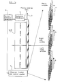
- the flat panel autostereoscopic 3D display shown in Figure la comprises an SLM 1, for instance in the form of a thin film transistor twisted nematic LCD, which is illuminated from the rear by a backlight (not shown).
- the display is arranged to supply left and right views for the left and right eyes, respectively, of an observer.
- the SLM 1 has a plurality of pixels arranged as rows and columns and displays left and right eye views in a spatially multiplexed format. In particular, alternate columns of pixels display strips of the left and right views.
- a movable parallax optic 2 is associated with the SLM 1 and comprises a plurality of columns of parallax elements, each of which is associated with an adjacent pair of columns of pixels.
- the combination of the parallax optic 2 and the SLM 1 produces viewing zones i.e. regions of space from which an eye of the observer can see a single two dimensional (2D) image over the whole of the display.
- Viewing windows comprise the widest parts of the viewing zones and are located at the nominal observer longitudinal position.
- the viewing windows are produced in a plurality of lobes such that each lobe provides left and right windows for the left and right eyes, respectively, of the observer.
- the parallax optic 2 is movable relative to the SLM 1 so as to move the viewing zones and hence the viewing windows to different locations within a region from which the observer may view the display.
- the parallax optic 2 may also be movable longitudinally i.e. perpendicularly to the SLM 1, so as to move the viewing plane longitudinally of the display in order to track longitudinal movement of the observer.
- the window width stays the same but the depth of the viewing zones is changed depending on direction of movement.
- the display comprises an observer tracker 7 which determines the position of an observer relative to the display.
- An example of such an observer tracker is known as Dynasight (TM) which uses infrared energy to illuminate the viewing region and detects reflections from a retroreflector worn by the observer.
- TM Dynasight
- Such a system is available from Origin Instruments Corporation.
- the observer tracker 7 includes a control system which is connected to an electromechanical system for moving the parallax optic 2.
- the electromechanical system comprises an electromechanical transducer 8, such as a stepper motor, servo motor or voice coil stage, connected by a mechanical transmission 9 to the parallax optic 2.
- the observer tracker and control system 7 supply signals to the electromechanical system so as to move the parallax optic 2 in a step wise manner to the appropriate one of a plurality of stationary positions which causes the left and right view windows to be located at the left and right eyes, respectively, of the observer.
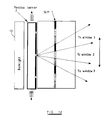
- Figure 1b shows a display of the type shown in Figure 1a comprising a backlight 10 for illuminating the SLM 1.
- the parallax optic 2 is embodied as a lenticular screen disposed between the SLM 1 and the observer. This arrangement provides three viewing windows in each output lobe of the lenticular screen 2.
- Figure 1c shows a display which differs from that shown in Figure 1b in that the lenticular screen is replaced by a parallax barrier 2.
- Figure 1d shows a display which differs from that shown in Figure 1c in that the parallax barrier 2 is located between the SLM 1 and the backlight 10.
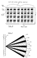
- FIG 2 illustrates a known type of LCD comprising a plurality of pixels arranged as rows and columns in a regular pattern or array.
- the LCD 1 provides a colour display and comprises red pixels 12, blue pixels 13 and green pixels 14.
- the pixels are separated from each other by a black mask 15.
- the black mask 15 obscures components such as transistors, capacitors and electrodes used to control the transmission of the pixels.
- each column of pixels is separated from each adjacent column by a continuous vertical opaque strip of the black mask 15.
- the LCD 1 is shown in association with a front lenticular screen 2 to provide a display of the type shown in Figure 1b.
- the lenticular screen 2 comprises a plurality of vertically extending lenticules, each of which is optically cylindrically converging.
- the lenticules extend vertically and may be formed, for instance, as plano-convex cylindrical lenses as graded refractive index (GRIN) cylindrical lenses, or as diffractive optical elements.
- GRIN graded refractive index
- Each lenticule is disposed above a plurality of columns of pixels (four columns as shown in Figure 2) and each column of pixels provides a vertical slice of a 2D view.
- the shape of each pixel is rectangular with a small rectangular extension projecting from the right side of each pixel.
- each lenticule of the screen 2 provides output light beams 17 to 20 from the respective four columns of pixels associated with the lenticule.
- the directions in which the light beams 17 to 20 extend correspond to the directions from which the respective 2D views were recorded during image capture.
- the vertical portions of the black mask 15 between the columns of pixels are also imaged in the directions indicated at 21 to 25.
- the light beams 17 to 20 contain regions such as 26 to 28 of reduced brightness corresponding to imaging of the rectangular protrusions extending from the main pixel regions.
- the output of the display does not have continuous parallax of even illumination.
- each pixel may be a composite pixel comprising a red pixel 12, a blue pixel 13 and a green pixel 14.
- the pixels are arranged such that they are contiguous in the horizontal direction. In other words, there are no continuous vertical black mask portions separating the pixels.
- each composite pixel 30 in a first row is spaced vertically from a horizontally adjacent composite pixel 31 in a second row but the right hand edge of the composite pixel 30 lies on the same vertical line as the left hand edge of the composite pixel 31.
- the number of columns of pixels imaged by each lenticule of the screen 2 has been doubled to 8 whereas the vertical resolution of the LCD 1 has effectively been halved.
- each lenticule of the screen 2 supplies eight output light beams 32 to 39 which are angularly contiguous with each other and which represent eight different 2D views with continuous horizontal parallax.
- "black” regions such as 21 and “grey” regions such as 26 in Figure 3 are eliminated and an observer can perceive a 3D image of substantially constant intensity and without image gaps.
- the pixel configuration shown in Figure 4 is that disclosed in EP 0 625 861. Because the vertical apertures of the pixels are constant, movement of an observer eye within each viewing window does not give rise to any undesirable visual artefacts. In particular, the image brightness is substantially constant so that no flicker or changes in brightness occur as an observer moves.
- Parallax barrier systems for instance of the type shown in Figure 1c and 1d, have an optical resolution limited by the slit width due to the geometrical width of the slit and diffraction effects of the slit.
- Lenticular screens for instance as shown in Figure 1b, have a resolution limited by aberrations, scatter, defocus and defects in thickness and pitch.
- the pupil of an observer's eye is imaged to a spot or strip of finite size at the plane of the SLM 1. This is referred to as an "eye spot".
- Figure 6 illustrates how the pupil 40 of the observer's eye is imaged by each lenticule of the screen 2 to an eye spot 41 in the form of a vertical stripe of finite width.
- the eye of the observer receives light from within the whole of the eye spot when the display is in use.
- the width and intensity profile of the eye spot vary with viewing position.
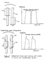
- the upper part of Figure 7 shows the position and size of the eye spots 40 and 42 imaged at pixels 43 and 44 of an LCD having the pixel configuration illustrated in Figure 4.
- the upper part of Figure 7 also illustrates the window intensity profile with lateral position of the eye spots 40 and 42 with respect to the pixels 43 and 44.
- the eye spots cover the centres of the two adjacent pixels 43 and 44.
- the mechanical steering system shown in Figure la provides movement of the parallax optic 2 with respect to the SLM 1 so that the eye spots 40 and 42 are nominally positioned about the centre of the pixels as the observer moves, for instance as illustrated in Figure 8.
- the lower part of Figure 7 illustrates eye spot overlap for another conventional pixel configuration with the pixels shaped as shown at 45 and 46.
- the window intensity profile for this configuration is also shown and illustrates that any movement of the eye spots 40 and 42 with respect to the pixels 45 and 46 will give rise to intensity variation so that the brightness of the images perceived by the observer will vary with movement of the observer. Dynamic intensity fluctuations of more than 5% can be seen by an observer as image flicker.
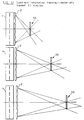
- the pitch of the parallax elements of the parallax optic 2 is slightly less than the pitch of the pairs of columns of pixels.
- the parallax element 2a at the right hand side of the display produces light "wedges" L1 and R1 corresponding to the left and right eye image slices.
- the parallax element 2b at the left hand side of the display produces light wedges L2 and R2 for the left and right eye view slices of the pixel columns aligned with the element 2b.
- the other parallax elements produce similar left and right eye light wedges directed towards left and right eye viewing zones LZ and RZ. Provided the left eye of the observer remains within the left eye viewing zone LZ, the left eye will see the left eye image across the whole of the display. Similarly, provided the right eye of the observer remains within the right eye viewing zone RZ, the right eye will see the right eye image across the whole of the display.
- the maximum longitudinal extent of the view point corrected stereoscopic viewing zones is indicated at LE1.
- the lower part of Figure 9 illustrates the viewing zones produced by a pixel configuration of the type illustrated in the lower part of Figure 7.
- the light intensity varies angularly within the light wedges L1, R1, L2 and R2 because the pixels are of non uniform vertical aperture.
- the columns of pixels are spaced by vertical strip portions of the black mask of the SLM, there are "black" wedges B1 and B2 between the light wedges L1 and R1 and between L2 and R2.
- an observer eye positioned within the black wedge B1 or B2 will not receive light from the pixels but will instead view the black mask.
- the viewing zones LZ and RZ for the pixel arrangement illustrated in the lower part of Figure 9 are spatially restricted compared with those of the upper part of Figure 9 and the extent LE1 of the longitudinal viewing freedom is substantially reduced compared with that for the pixel arrangement of Figure 4.
- the brightness will vary as the eyes of the observer move within the viewing zones LZ and RZ.
- pixel configurations having uniform or constant vertical aperture and of extended horizontal aperture provide greater longitudinal viewing freedom in viewpoint corrected displays.
- the pixel configuration of Figure 4 substantially enhances the performance of the display within the useful viewing region.
- the intensity profile is uniform across the central portion of the window. If an observer moves slightly, the mechanical system will take a time to catch up with the observer but, as the window intensity remains unchanged, no artefact will be seen.
- the response speed of the tracking system is constrained by pixel shape. If an observer moves too quickly such that the tracking system cannot respond sufficiently quickly, the eye spot can move out of the pixel boundary so that image flicker is visible. It is therefore desirable for the pixel to be larger and to have a more uniform aperture so that the display is more resistant to system lags or delays.
- movement of the parallax optic 2 is quantised such that the electromechanical transducer 8 and the mechanical transmission 9 make stepwise movements among a plurality of stationary positions of the optic 2.
- the eye spots can move some distance within the pixels before any change in intensity or cross-talk is visible in the 3D image.
- the parallax optic 2 can move from one position to an adjacent position with substantially no change in the display appearance.
- the windows move in correspondence with movement of the parallax optic 2.
- the optimum window size is generally equal to the average interocular separation which is approximately 65mm.
- the pixels are substantially horizontally contiguous so as to produce substantially contiguous viewing windows, it may be advantageous to provide windows which are larger than the average interocular separation. This is because, as the observer eyes move away from the optimum position, one eye approaches a window boundary, whereas the other remains in a "good" part of the window. If the boundary quality is high, the artefact seen by the eye approaching the boundary is not too bad and the other eye sees no artefact. The overall image quality is therefore improved. For non-contiguous underlapping pixels, the use of larger windows also increases the gap between adjacent windows so that viewing freedom is reduced.
- Figures 10a to 10d show four pixel arrangements for providing only two views.
- Figure 10a shows a pixel configuration of the type shown in Figure 4 to provide high image resolution.
- undesirable cross-talk may occur because of the horizontal contiguity of the adjacent pairs of pixel columns.
- the arrangements shown in Figures 10b and 10c may be adopted.
- every third column of pixels may be switched to a fixed black or grey level so as to provide horizontal spacing between the pairs of columns of pixels.
- the black mask may be extended as illustrated in Figure 10c.
- the pixel configuration illustrated in Figure 10d allows the same windows to be generated as that illustrated in Figure 10c.
- the vertical resolution of the display is not sacrificed and the black mask regions between the pairs of columns of pixels are maintained.
- the window size can be increased to improve the visual performance of the tracking system.
- the width of the small gaps between the pixels in each pair of columns may be of the order of a few microns with components such as addressing electrodes, capacitors and transistors being disposed in the gaps between the pairs of pixel columns so as to be covered by the black mask.
- Such an arrangement provides a display with a higher aperture ratio than that of Figure 10c having a similar tracking performance, so that a brighter display can be provided.
- Electromechanical systems which can provide quantised step size include stepper motors, DC servo motors with quantised position encoders and voice coil stages with quantised position encoders. Such systems may comprise gear systems or lead or ball screws provided the backlash is lower than the quantised step size.
- the display exhibits a finite non-zero response time t between measurement of the observer position and movement of the parallax optic 2 to optimise viewing conditions for the observer position. This results from such factors as measurement latencies in the sensor of the observer tracker 7, communication time from the sensor to a control system within the tracker 7 and from the control system to the transducer 8, processing of measurement information and comparison with calibration information, and mechanical response time of the electromechanical system and the parallax optic 2.
- the display should be capable of moving to the best position and does not stop at intermediate positions.
- the display adapts to observer speed of movement to determine the best displacement. A jump may therefore cover a number of calibrated positions.
- the display will have a variable number of steps per instruction from the control system.
- step size Another consideration in the step size is related to the absolute accuracy of the sensor when determining the position of the observer. If the sensor determines the position with a random error of maximum size ⁇ x, there is no point in the display having a window step size of less than this value.
- the optimum step size derived from the above equation is valid only at the window plane. Away from the window plane, the step size given by the equation may be close to or greater than the actual usable window width. In this case, the optimum step size becomes a fraction of the actual usable window width (ie: the lateral freedom in the viewing region) at the viewing distance and the maximum allowed observer lateral speed Vmax must decrease.
- the number of stationary points may be varied with longitudinal observer position. This means that the display may respond more accurately but more slowly for an observer positioned out of the window plane.
- the same basic calculation of step size may apply but the effective window width is changed accordingly with longitudinal position as the observer moves around within the viewing regions. Alternatively, the number of steps may be increased to some maximum so as to minimise the loss in tracking speed while providing some improvement in tracking accuracy.
- n' n + (2/ ⁇ z// ⁇ L)(e/ ⁇ x-n) where / ⁇ n/ is the absolute value of the distance from the current longitudinal or z position of the observer to the optimum viewing distance and ⁇ L is the longitudinal length of the viewing regions.
- n' n + (2/ ⁇ z// ⁇ L)(e/ ⁇ x-n)
- / ⁇ n/ is the absolute value of the distance from the current longitudinal or z position of the observer to the optimum viewing distance
- ⁇ L is the longitudinal length of the viewing regions.
- quantising the movement of the display has advantages in detailed product development and takes into account the practical response of control systems.
- Calibration of the display may, for example, be performed as described in EP 0 769 881.
- Calibration of the display may, for example, be performed as described in EP 0 769 881.
- EP 0 769 881 In particular:
- the data from the observer tracker may represent angular information of the observer position with respect to the display.
- each linear translation of the parallax optic causes an angular shift in the viewing zones so that, if the optical axes of the display and the tracking system coincide, the angular observer position can be used directly to determine the required position of the parallax optic.
- the calibration points are purely related to the angular observer position and, for each angular position, there is a unique corresponding position of the electromechanical system. Otherwise, operation of the display is as described hereinbefore.
- This control arrangement has several advantages. Because only a limited number of tracking position steps is required, there is only a limited number of calibration points. The memory of the control system may, therefore, be limited. Also, the number of calculations which must be performed to find the nearest calibration line is limited so that the system latency is reduced. The speed of the control system and the cost of the component parts may, therefore, be reduced without any significant reduction in display performance. This contrasts with a continuous tracking system in which continuous on-line calibration best-fit would be required in order to find the best parallax optic position. This would lead to increased display cost and reduced tracking efficiency.
- the parallax optic 2 may be moved longitudinally in a stepwise manner as illustrated in Figure 11.
- the window plane containing the windows 50 moves longitudinally relative to the display but the window sizes remain of constant width.
- the viewing zones change in size longitudinally.
- the position data obtained by the observer tracker 7 may be used so that the observer is substantially maintained at the window plane.
- the window plane is then always substantially at the optimum position for lateral tracking because the window size is at its largest. This allows greater reduction in tolerance requirements of the system and can further reduce the step size of the mechanical tracking system, thus reducing cost and increasing robustness. Further, the available viewing region for the observer is substantially increased in size, particularly in the longitudinal depth range.
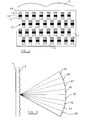
- Figure 12 illustrates at 55 the allowed viewing range of an observer for 3D autostereoscopic viewing.
- the lateral or horizontal allowed viewing range 55 is limited, as indicated at 56 and 57, by optical performance such as optical aberration of a lenticular screen.
- the vertical viewing range is limited at 58 and 59 by the geometric construction of the display and by optical aberrations of the parallax optic. Outside the range 55, it is not possible to perceive a 3D image.
- the performance of the display may be improved by switching off the display when the observer tracker detects that the observer is outside the range 55.
- the observer tracker supplies out of range tracking information 60 which may be used, as shown diagrammatically in Figure 12, to switch off the backlight 10 so as to prevent incorrect viewing. Alternately, this information may be used to switch off the SLM 1. Further, the intensity of the image may be made to fade as the observer moves towards the edges of the viewing range 55. In this way, the limited viewing freedom is made to feel more natural to an observer.
- the parallax optic 2 may be tilted relative to the SLM 1 so as to change the distances of the windows for observers located away from the central axis of the display. This may be adopted in addition to a lateral tracking system so as to provide improved viewer freedom. Tilting may be performed in a stepwise manner as described hereinbefore.
- the parallax optic comprises superimposed masks 66 and 67 which are movable relative to each other.
- Each of the masks comprises a plurality of transparent stripes separated by checkerboard patterns of transmissive and non-transmissive square regions.
- the checkerboard patterns of the masks 66 and 67 are complementary to each other so that, when the masks are aligned as shown in the upper part of Figure 14, the transmissive stripes are aligned to form the parallax optic but, in the intervening regions, each transmissive square of each of the masks 66 and 67 is aligned with a non-transmissive region of the other mask.
- the vertical slits 69 are separated from each other by non-transmissive regions such as 70 and 71.
- the resulting optical component has the transmission properties illustrated at 72.
- the SLM displays a regular array of transmissive and non-transmissive regions so that the directional restrictions on viewing the display are removed and 2D images at the full resolution of the SLM 1 may be displayed.
- the vertical size of the checkerboard regions are chosen to minimise Moiré beating between the LCD pixels and the checkerboard pattern.
- the masks 66 and 67 differ from those shown in Figure 14 in that the patterns between the vertical transmissive strips are made up of strip polarisers whose polarisation directions are shown by the arrows. With the relative positions shown at the upper part of Figure 15, the strips of the two masks 66 and 67 are aligned whereas each polarised region of the mask 67 is aligned with a strip of the orthogonal polarisation. Thus, a parallax barrier as illustrated at 68 is produced.
- the parallax optic 2 operates as a polariser to allow the display to be observed from a greater range of angles for the 2D mode.
- the polarisation directions of the strips are aligned at 45 degrees to the output polarisation of the SLM 1 when, for instance, embodied as an LCD.
- 90 degree polarisation rotators may be disposed on the sheet nearest the LCD to reorient the polarisation to the second polariser sheet, this being more light efficient.
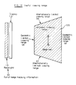
- Figure 16 illustrates another type of parallax barrier 2 which may be used to switch between autostereoscopic 3D viewing and 2D full resolution non-directional viewing.
- the parallax barrier comprises a first layer comprising strips of 90 degrees polarisation rotators such as ⁇ /2 plates 75 which are separated by regions such as 76 which do not substantially affect the polarisation of the transmitted light.
- a polarising sheet 77 whose polarising axis is oriented vertically is disposed between the observer and the first sheet. When illuminated by polarised light in the direction 78 (such as the polarised output from an LCD) and with the direction of polarisation 79, light passes through the neutral regions 76 but is blocked by the polarising sheet 77.
- the ⁇ /2 strips 75 rotate the polarisation of the incident light by 90 degrees so that the polarising sheet 77 transmits this light.
- the device therefore functions as a parallax barrier.
- the polarising sheet 77 is removed and the regions 76 and waveplates 75 transmit the light.
- the polarising sheet 77 may be aligned with the polarisation direction 79 and the ⁇ /2 strips wound in and out to give the 3D and 2D modes, respectively.
- the ⁇ /2 strips define the dark regions and the clear areas define the transmissive slits.
- the absorbtion of the neutral (non-polarising) regions can be made the same as the absorbtion loss of the polarisers so that the visibility of the chequerboard arrangement is minimised while providing the switchable modes.
- the sheet comprising the regions 76 and the waveplates 75 is moved to provide observer tracking but the polarising sheet 77 need not move and may be made detachable.
- the polarising sheet 77 need only be aligned in rotation and not in lateral registration, thus simplifying assembly.
- Such an arrangement may be made relatively slim and the separation between the polarising sheet and the first sheet does not affect operation.
- the polarising sheet may be stuck on the outside of the main unit if required or may even by worn in the form of glasses.
- Optical efficiency is relatively high because there is only one polariser absorption loss in the 3D mode and full brightness is provided in the 2D mode.
- Figure 17 illustrates schematically an arrangement for switching the arrangement of Figure 16 between the 3D and 2D modes.
- the polarising sheet 77 is connected to a clear film which may then be wound across the front of the display by a mechanism 80 such that the polarising sheet is in front of the display for the 3D mode and the clear film is in front of the display for the 2D mode.
- the arrangement of Figure 17 may be modified by replacing the ⁇ /2 plates 75 with + ⁇ /4 plates and replacing the regions 76 with - ⁇ /4 plates.
- the polarising sheet 77 is replaced by a sandwich arrangement comprising a + ⁇ /4 sheet and a polarising sheet.
- the window size at the optimum viewing distance i.e. in the window plane does not change if the parallax optic 2 is moved longitudinally with respect to the LCD 1.
- the parallax optic will always move by a constant distance so as to compensate for observer movement in the window plane.
- the lateral calibration of the display does not therefore vary with longitudinal window distance.
- Figure 18 illustrates an alternate manual arrangement for longitudinal observer tracking. This arrangement continues to provide automatic mechanical lateral tracking of the observer.
- the position of the parallax optic 2 relative to the LCD 1 is manually adjustable by an adjuster 51, for instance of a simple screw adjustment type.
- a longitudinal position encoder 52 is provided to supply a signal corresponding to the longitudinal position of the parallax optic 2 relative to the LCD 1.
- the observer positions himself at the most comfortable position with respect to the display.
- the observer then manually adjusts the longitudinal position of the parallax optic 2 by means of the adjuster 51 so as to give the best image quality i.e. so that the parallax optic 2 is positioned so as to maintain the window plane at the observer. Because the lateral calibration has not changed, the display continues to track the observer accurately for lateral movement. It is thus possible to provide a simple robust system which is cost-effective for providing enhanced viewing freedom.
Landscapes
- Engineering & Computer Science (AREA)
- Multimedia (AREA)
- Signal Processing (AREA)
- Physics & Mathematics (AREA)
- General Physics & Mathematics (AREA)
- Optics & Photonics (AREA)
- Testing, Inspecting, Measuring Of Stereoscopic Televisions And Televisions (AREA)
Applications Claiming Priority (2)
| Application Number | Priority Date | Filing Date | Title |
|---|---|---|---|
| GB9619097A GB2317291A (en) | 1996-09-12 | 1996-09-12 | Observer tracking directional display |
| GB9619097 | 1996-09-12 |
Publications (3)
| Publication Number | Publication Date |
|---|---|
| EP0829743A2 true EP0829743A2 (de) | 1998-03-18 |
| EP0829743A3 EP0829743A3 (de) | 1998-12-02 |
| EP0829743B1 EP0829743B1 (de) | 2005-03-30 |
Family
ID=10799853
Family Applications (1)
| Application Number | Title | Priority Date | Filing Date |
|---|---|---|---|
| EP97307083A Expired - Lifetime EP0829743B1 (de) | 1996-09-12 | 1997-09-12 | Richtungsabhängiges Anzeigesystem mit Benutzerfolgesystem |
Country Status (5)
| Country | Link |
|---|---|
| US (1) | US6377295B1 (de) |
| EP (1) | EP0829743B1 (de) |
| JP (1) | JP3401167B2 (de) |
| DE (1) | DE69732885T2 (de) |
| GB (1) | GB2317291A (de) |
Cited By (22)
| Publication number | Priority date | Publication date | Assignee | Title |
|---|---|---|---|---|
| WO2000036845A1 (en) * | 1998-12-15 | 2000-06-22 | Street Graham S B | Apparatus and method for stereoscopic image control |
| WO2002009446A1 (de) * | 2000-07-24 | 2002-01-31 | HEINRICH-HERTZ-INSTITUT FüR NACHRICHTENTECHNIK BERLIN GMBH | Strukturplatte für monoskopische und stereoskopische bilddarstellung auf flachbildschirmen |
| WO2002099510A1 (en) | 2001-06-01 | 2002-12-12 | Sony Corporation | 3-d image display unit, display unit, or split wavelengthe plate filter mounted on these dsplay units, platy filter, and filter position adjusting mechanism, positioning device, and filter position adjusting method, positioning method |
| WO2005006777A2 (en) * | 2003-07-10 | 2005-01-20 | Ocuity Limited | Pixel arrangement for an autostereoscopic display apparatus |
| EP1542477A2 (de) * | 2003-12-10 | 2005-06-15 | Samsung Electronics Co., Ltd. | 2D und 3D Anzeigevorrichtung |
| GB2418315A (en) * | 2004-09-21 | 2006-03-22 | Sharp Kk | Multiple view display |
| US7058252B2 (en) | 2001-08-06 | 2006-06-06 | Ocuity Limited | Optical switching apparatus |
| WO2008100826A1 (en) | 2007-02-13 | 2008-08-21 | Clairvoyante, Inc | Subpixel layouts and subpixel rendering methods for directional displays and systems |
| US7426068B2 (en) | 2005-01-10 | 2008-09-16 | Au Optronics Corporation | Display apparatus |
| US7532272B2 (en) | 2003-02-05 | 2009-05-12 | Au Optronics Corp. | Switchable lens |
| WO2009062752A1 (de) * | 2007-11-15 | 2009-05-22 | Fraunhofer-Gesellschaft zur Förderung der angewandten Forschung e. V. | Verfahren und vorrichtung zum autostereoskopischen darstellen von bildinformationen |
| WO2009136218A1 (en) * | 2008-05-06 | 2009-11-12 | Microvision Inc. | An apparatus for displaying 3 d images |
| US7830357B2 (en) | 2004-07-28 | 2010-11-09 | Panasonic Corporation | Image display device and image display system |
| CN103152592A (zh) * | 2011-11-22 | 2013-06-12 | Lg电子株式会社 | 三维图像处理装置及其校准方法 |
| EP2395762A3 (de) * | 2010-06-10 | 2013-10-30 | LG Electronics Inc. | Mobiles Endgerät und Steuerungsverfahren dafür |
| WO2014025781A1 (en) * | 2012-08-10 | 2014-02-13 | Pixtronix, Inc. | Three dimensional (3d) image generation using electromechanical display elements |
| CN104297994A (zh) * | 2014-10-31 | 2015-01-21 | 深圳市华星光电技术有限公司 | 集成成像3d液晶显示器及其使用的光学设备 |
| EP2988167A1 (de) * | 2014-08-18 | 2016-02-24 | LG Display Co., Ltd. | 3d-anzeigevorrichtung zur reduzierung der bewegung von flimmern |
| WO2021196369A1 (zh) * | 2020-04-03 | 2021-10-07 | 中山大学 | 基于子像素出射光空间叠加的三维显示方法 |
| EP2878129B1 (de) * | 2012-07-24 | 2023-06-07 | Alioscopy | Verfahren zur autostereoskopischen anzeige auf einem bildschirm mit einer grösseren grösse in vertikaler richtung |
| EP4120006A4 (de) * | 2021-01-25 | 2023-06-21 | BOE Technology Group Co., Ltd. | Anzeigevorrichtung und ansteuerungsverfahren dafür |
| US12051344B2 (en) | 2021-01-25 | 2024-07-30 | Boe Technology Group Co., Ltd. | Display apparatus with light-splitting component and driving method thereof |
Families Citing this family (154)
| Publication number | Priority date | Publication date | Assignee | Title |
|---|---|---|---|---|
| GB2324428A (en) * | 1997-04-17 | 1998-10-21 | Sharp Kk | Image tracking; observer tracking stereoscopic display |
| GB2337388A (en) * | 1998-05-12 | 1999-11-17 | Sharp Kk | Directional autereoscopic 3D display having directional illumination system |
| JP2000250697A (ja) * | 1999-03-03 | 2000-09-14 | Yazaki Corp | 多機能スイッチ装置における操作ボタンの機能表示方法及び多機能スイッチ装置 |
| EP1122957A1 (de) * | 2000-02-02 | 2001-08-08 | THOMSON multimedia | Dreidimensionale Bildanzeigevorrichtung |
| US20080024598A1 (en) * | 2000-07-21 | 2008-01-31 | New York University | Autostereoscopic display |
| US7001019B2 (en) * | 2000-10-26 | 2006-02-21 | Canon Kabushiki Kaisha | Image observation apparatus and system |
| TW476002B (en) * | 2001-05-31 | 2002-02-11 | Ind Tech Res Inst | Vertical parallax barrier bare eye three-dimensional display device |
| JP2004029852A (ja) * | 2001-06-01 | 2004-01-29 | Sony Corp | 立体画像表示装置のフィルター位置調整方法 |
| JP2002365593A (ja) * | 2001-06-08 | 2002-12-18 | Sony Corp | 表示装置、位置調整パターン表示プログラム、記録媒体、偏光メガネ、及び表示装置のフィルター位置調整方法 |
| JP2005505793A (ja) * | 2001-10-02 | 2005-02-24 | ゼーレアル・テヒノロギース・ゲゼルシャフト・ミト・ベシュレンクテル・ハフツング | 情報を空間立体的に、および/またはホログラフィーにより表示するための前置マスクを有する平面ディスプレイ |
| US7055851B2 (en) * | 2001-11-22 | 2006-06-06 | Toyoda Gosei Co., Ltd. | Knee protecting airbag device |
| JP2003299121A (ja) * | 2002-04-05 | 2003-10-17 | Canon Inc | 立体画像表示装置および立体画像表示システム |
| JP2004007566A (ja) * | 2002-04-24 | 2004-01-08 | Canon Inc | 立体画像表示装置および立体画像表示システム |
| GB2390172A (en) * | 2002-06-28 | 2003-12-31 | Sharp Kk | Polarising optical element and display |
| JP4287105B2 (ja) * | 2002-08-22 | 2009-07-01 | 株式会社バンダイナムコゲームス | 立体視映像表示装置及び電子機器 |
| GB2393344A (en) * | 2002-09-17 | 2004-03-24 | Sharp Kk | Autostereoscopic display |
| JP4403688B2 (ja) * | 2002-10-11 | 2010-01-27 | ソニー株式会社 | 偏光手段、及びその位置保持機構 |
| US20040075735A1 (en) * | 2002-10-17 | 2004-04-22 | Koninklijke Philips Electronics N.V. | Method and system for producing a pseudo three-dimensional display utilizing a two-dimensional display device |
| JP3923434B2 (ja) * | 2003-01-28 | 2007-05-30 | 株式会社ソフィア | 画像表示装置 |
| US20040196369A1 (en) * | 2003-03-07 | 2004-10-07 | Canon Kabushiki Kaisha | Monitoring system |
| US7872635B2 (en) | 2003-05-15 | 2011-01-18 | Optimetrics, Inc. | Foveated display eye-tracking system and method |
| US7580559B2 (en) * | 2004-01-29 | 2009-08-25 | Asml Holding N.V. | System and method for calibrating a spatial light modulator |
| GB0410551D0 (en) * | 2004-05-12 | 2004-06-16 | Ller Christian M | 3d autostereoscopic display |
| US20060007191A1 (en) * | 2004-06-03 | 2006-01-12 | International Business Machines Corporation | System and method for adjusting a screen |
| DE102005020871B4 (de) * | 2004-06-07 | 2013-03-28 | Siemens Aktiengesellschaft | Verfahren zur Darstellung von medizinischen Bildinformationen auf einem Anzeigemedium |
| TW200604712A (en) * | 2004-06-08 | 2006-02-01 | Actuality Systems Inc | Optical scanning assembly |
| US7561217B2 (en) * | 2004-09-09 | 2009-07-14 | Au Optronics Corporation | Liquid crystal display apparatus and method for improving precision 2D/3D viewing with an adjustable backlight unit |
| WO2006043721A1 (ja) * | 2004-10-20 | 2006-04-27 | Fujitsu Ten Limited | 表示装置 |
| WO2006043720A1 (ja) | 2004-10-20 | 2006-04-27 | Fujitsu Ten Limited | 表示装置、表示装置の画質調整方法、画質調整装置、およびコントラスト調整装置 |
| DE602005010112D1 (de) * | 2004-10-25 | 2008-11-13 | Koninkl Philips Electronics Nv | Anzeigevorrichtung |
| WO2006046750A1 (ja) * | 2004-10-27 | 2006-05-04 | Fujitsu Ten Limited | 表示装置 |
| US20080068284A1 (en) * | 2004-10-27 | 2008-03-20 | Fujitsu Ten Limited | Display Device |
| JP2006154759A (ja) * | 2004-10-29 | 2006-06-15 | Fujitsu Ten Ltd | 画像補間装置、および表示装置 |
| EP1808845A4 (de) * | 2004-11-02 | 2011-05-25 | Fujitsu Ten Ltd | Anzeigesteuereinrichtung und anzeigeienrichtung |
| JP2006154756A (ja) * | 2004-11-02 | 2006-06-15 | Fujitsu Ten Ltd | 映像信号処理方法、映像信号処理装置、及び、表示装置 |
| KR101113235B1 (ko) * | 2004-11-29 | 2012-02-29 | 삼성전자주식회사 | 입체 디스플레이 장치 |
| JP2006189782A (ja) * | 2004-12-06 | 2006-07-20 | Fujitsu Ten Ltd | 表示装置 |
| JP2006195415A (ja) | 2004-12-13 | 2006-07-27 | Fujitsu Ten Ltd | 表示装置及び表示方法 |
| JP2007041489A (ja) * | 2004-12-14 | 2007-02-15 | Fujitsu Ten Ltd | 表示装置、枠部材および反射抑制部材 |
| KR101086411B1 (ko) * | 2005-04-04 | 2011-11-25 | 삼성전자주식회사 | 2차원/3차원 영상 호환용 입체 영상 디스플레이 장치 |
| US8675125B2 (en) | 2005-04-27 | 2014-03-18 | Parellel Consulting Limited Liability Company | Minimized-thickness angular scanner of electromagnetic radiation |
| US9176334B2 (en) * | 2005-06-28 | 2015-11-03 | Fujitsu Ten Limited | Display device and method for mounting the same |
| JP4215782B2 (ja) * | 2005-06-30 | 2009-01-28 | 富士通テン株式会社 | 表示装置、および表示装置の音声調整方法 |
| JP4372117B2 (ja) * | 2005-06-30 | 2009-11-25 | 富士通テン株式会社 | 受信装置 |
| EP1923852A4 (de) * | 2005-09-06 | 2010-06-30 | Fujitsu Ten Ltd | Anzeigeanordnung und anzeigeverfahren |
| JP5121456B2 (ja) * | 2005-09-20 | 2013-01-16 | 富士通テン株式会社 | 車載用表示装置 |
| JP2007083858A (ja) * | 2005-09-21 | 2007-04-05 | Fujitsu Ten Ltd | 車載用表示装置 |
| JP2007086381A (ja) * | 2005-09-21 | 2007-04-05 | Fujitsu Ten Ltd | 液晶表示装置 |
| JP2007086379A (ja) * | 2005-09-21 | 2007-04-05 | Fujitsu Ten Ltd | 車載用液晶表示装置 |
| US20070063943A1 (en) * | 2005-09-21 | 2007-03-22 | Fujitsu Ten Limited | Display apparatus |
| US7830602B2 (en) * | 2005-10-26 | 2010-11-09 | Nippon Sheet Glass Company, Limited | In-vehicle stereoimage display apparatus |
| WO2007052216A1 (en) * | 2005-11-04 | 2007-05-10 | Koninklijke Philips Electronics N.V. | Rendering of image data for multi-view display |
| JP2007145158A (ja) * | 2005-11-28 | 2007-06-14 | Fujitsu Ten Ltd | 車載用表示装置及びその表示制御方法 |
| US8976080B2 (en) * | 2005-12-06 | 2015-03-10 | Dolby Laboratories Licensing Corporation | Multi-segment imager |
| KR101614415B1 (ko) * | 2005-12-06 | 2016-04-21 | 돌비 레버러토리즈 라이쎈싱 코오포레이션 | 모듈식 전자 디스플레이 장치들 |
| JP4650279B2 (ja) * | 2006-01-19 | 2011-03-16 | エプソンイメージングデバイス株式会社 | 電気光学装置及び電子機器 |
| DE102006004301A1 (de) * | 2006-01-20 | 2007-08-02 | Seereal Technologies S.A. | Holographische Projektionsvorrichtung zur Vergrößerung eines Rekonstruktionsbereichs |
| JPWO2007097353A1 (ja) * | 2006-02-22 | 2009-07-16 | 富士通テン株式会社 | 表示装置及び表示方法 |
| JP2007265221A (ja) * | 2006-03-29 | 2007-10-11 | Sanyo Electric Co Ltd | 複数画像表示装置及び車載ナビゲーションシステム |
| JP4308219B2 (ja) * | 2006-04-14 | 2009-08-05 | 富士通テン株式会社 | 車載用表示装置 |
| JP2007283873A (ja) | 2006-04-14 | 2007-11-01 | Fujitsu Ten Ltd | 表示装置および車載用表示装置 |
| US20090309887A1 (en) * | 2006-04-19 | 2009-12-17 | Setred As | Bandwidth improvement for 3d display |
| JP2007308084A (ja) * | 2006-05-22 | 2007-11-29 | Fujitsu Ten Ltd | 車載用表示装置及び音響制御方法 |
| DE102006025096B4 (de) * | 2006-05-23 | 2012-03-29 | Seereal Technologies S.A. | Verfahren und Einrichtung zum Rendern und Generieren computer-generierter Videohologramme |
| JP2008241730A (ja) * | 2007-03-23 | 2008-10-09 | Fujitsu Ten Ltd | 表示制御装置、表示装置及び表示制御方法 |
| KR101387366B1 (ko) * | 2007-06-27 | 2014-04-21 | 삼성전자주식회사 | 다시점 입체 영상 표시 장치 및 영상 표시 방법 |
| KR20080114169A (ko) * | 2007-06-27 | 2008-12-31 | 삼성전자주식회사 | 3차원 영상 표시방법 및 이를 적용한 영상기기 |
| KR101380226B1 (ko) * | 2007-07-05 | 2014-04-02 | 엘지디스플레이 주식회사 | 3차원 영상구현 액정표시장치 |
| GB0716776D0 (en) * | 2007-08-29 | 2007-10-10 | Setred As | Rendering improvement for 3D display |
| US20090180180A1 (en) * | 2008-01-16 | 2009-07-16 | Samsung Electronics Co., Ltd. | Sub-pixel optical array |
| CN101226325B (zh) | 2008-02-03 | 2010-06-02 | 李志扬 | 基于随机相长干涉的三维显示方法及装置 |
| US20100053310A1 (en) * | 2008-08-31 | 2010-03-04 | Maxson Brian D | Transforming 3d video content to match viewer position |
| JP4547641B2 (ja) * | 2008-09-22 | 2010-09-22 | ソニー株式会社 | 位相差板の製造方法 |
| JP2010164668A (ja) * | 2009-01-14 | 2010-07-29 | Seiko Epson Corp | 電気光学装置及び電子機器 |
| JP5410548B2 (ja) * | 2009-02-03 | 2014-02-05 | エルジー・ケム・リミテッド | 立体映像表示装置用光学フィルタの製造方法 |
| US20120026418A1 (en) * | 2009-04-15 | 2012-02-02 | Kenichiro Tsuchida | Liquid crystal display apparatus |
| TWI399570B (zh) * | 2009-06-10 | 2013-06-21 | Au Optronics Corp | 立體顯示器以及立體顯示系統 |
| KR101057098B1 (ko) * | 2009-07-10 | 2011-08-16 | (주)엔디스 | 광시야각 입체 디스플레이의 휘도 플리커 제어장치 및 그 방법 |
| JP5403623B2 (ja) * | 2010-03-10 | 2014-01-29 | 株式会社ジャパンディスプレイ | 2画面表示装置 |
| CN102455516A (zh) * | 2010-10-22 | 2012-05-16 | 鸿富锦精密工业(深圳)有限公司 | 三维显示装置 |
| KR101732131B1 (ko) * | 2010-11-12 | 2017-05-04 | 삼성전자주식회사 | 사용자 위치 기반의 영상 제공 장치 및 방법 |
| CN101984670B (zh) * | 2010-11-16 | 2013-01-23 | 深圳超多维光电子有限公司 | 一种立体显示方法、跟踪式立体显示器及图像处理装置 |
| KR101290908B1 (ko) * | 2011-03-29 | 2013-07-29 | 가부시끼가이샤 도시바 | 3차원 영상 표시 장치 |
| WO2012134487A1 (en) * | 2011-03-31 | 2012-10-04 | Hewlett-Packard Development Company, L.P. | Adaptive monoscopic and stereoscopic display using an integrated 3d sheet |
| WO2012150940A1 (en) * | 2011-05-05 | 2012-11-08 | Empire Technology Development Llc | Lenticular directional display |
| WO2013027280A1 (ja) * | 2011-08-24 | 2013-02-28 | 株式会社東芝 | 画像処理装置及び方法、並びに、立体画像表示装置 |
| CN102510504B (zh) * | 2011-09-27 | 2015-04-15 | 深圳超多维光电子有限公司 | 裸眼立体显示系统的显示范围确定及显示方法及装置 |
| KR101887058B1 (ko) * | 2011-11-11 | 2018-08-09 | 엘지전자 주식회사 | 입체영상 처리 장치 및 입체영상 처리 장치의 전력 제어 방법 |
| DE102011089705A1 (de) * | 2011-12-22 | 2013-06-27 | Carl Zeiss Vision International Gmbh | Sehprüfgerät |
| JP5762998B2 (ja) * | 2012-03-07 | 2015-08-12 | 株式会社ジャパンディスプレイ | 表示装置および電子機器 |
| EP2653906B1 (de) | 2012-04-20 | 2022-08-24 | Dolby Laboratories Licensing Corporation | System zum Liefern von stereoskopischen Bildern |
| US9709723B2 (en) | 2012-05-18 | 2017-07-18 | Reald Spark, Llc | Directional backlight |
| US9188731B2 (en) | 2012-05-18 | 2015-11-17 | Reald Inc. | Directional backlight |
| US9678267B2 (en) | 2012-05-18 | 2017-06-13 | Reald Spark, Llc | Wide angle imaging directional backlights |
| US9235057B2 (en) | 2012-05-18 | 2016-01-12 | Reald Inc. | Polarization recovery in a directional display device |
| US10062357B2 (en) | 2012-05-18 | 2018-08-28 | Reald Spark, Llc | Controlling light sources of a directional backlight |
| CN104487877A (zh) | 2012-05-18 | 2015-04-01 | 瑞尔D股份有限公司 | 定向显示设备 |
| EP2875638A4 (de) * | 2012-07-23 | 2016-03-30 | Reald Inc | Autostereoskopische anzeige zur beobachterverfolgung |
| US9584797B2 (en) | 2012-10-31 | 2017-02-28 | Elwha Llc | Systems and methods to confirm that an autostereoscopic display is accurately aimed |
| KR102055134B1 (ko) * | 2013-01-11 | 2020-01-22 | 엘지디스플레이 주식회사 | 3차원영상 표시장치 및 그 구동방법 |
| EP2959213A4 (de) | 2013-02-22 | 2016-11-16 | Reald Inc | Direktionale rückbeleuchtung |
| KR102028987B1 (ko) * | 2013-03-29 | 2019-10-07 | 엘지디스플레이 주식회사 | 홀로그램 영상 표시 장치 |
| JP2016529764A (ja) | 2013-06-17 | 2016-09-23 | リアルディー インコーポレイテッド | 指向性バックライトの光源の制御 |
| TWI477817B (zh) * | 2013-07-18 | 2015-03-21 | Au Optronics Corp | 顯示器以及顯示具有不同視差的三維影像的方法 |
| KR102366346B1 (ko) | 2013-10-14 | 2022-02-23 | 리얼디 스파크, 엘엘씨 | 지향성 백라이트를 위한 광 입력 |
| CN106068533B (zh) | 2013-10-14 | 2019-01-11 | 瑞尔D斯帕克有限责任公司 | 定向显示器的控制 |
| CN103945203A (zh) | 2013-12-19 | 2014-07-23 | 上海天马微电子有限公司 | 一种立体图像显示装置 |
| TWI549476B (zh) | 2013-12-20 | 2016-09-11 | 友達光電股份有限公司 | 顯示系統及調整可視範圍的方法 |
| CN103698933B (zh) | 2013-12-30 | 2017-03-29 | 京东方科技集团股份有限公司 | 立体显示器 |
| TWI507015B (zh) * | 2014-02-20 | 2015-11-01 | Au Optronics Corp | 三維影像之調整方法及採用此方法之三維顯示器 |
| JP6516234B2 (ja) * | 2014-04-24 | 2019-05-22 | Tianma Japan株式会社 | 立体画像表示装置 |
| JP6962521B2 (ja) | 2014-06-26 | 2021-11-05 | リアルディー スパーク エルエルシー | 指向性プライバシーディスプレイ |
| US9835792B2 (en) | 2014-10-08 | 2017-12-05 | Reald Spark, Llc | Directional backlight |
| JP2015084110A (ja) * | 2014-12-04 | 2015-04-30 | 株式会社ジャパンディスプレイ | 表示装置 |
| WO2016105541A1 (en) | 2014-12-24 | 2016-06-30 | Reald Inc. | Adjustment of perceived roundness in stereoscopic image of a head |
| US10701349B2 (en) * | 2015-01-20 | 2020-06-30 | Misapplied Sciences, Inc. | Method for calibrating a multi-view display |
| US11099798B2 (en) | 2015-01-20 | 2021-08-24 | Misapplied Sciences, Inc. | Differentiated content delivery system and method therefor |
| US10955924B2 (en) | 2015-01-29 | 2021-03-23 | Misapplied Sciences, Inc. | Individually interactive multi-view display system and methods therefor |
| US10928914B2 (en) | 2015-01-29 | 2021-02-23 | Misapplied Sciences, Inc. | Individually interactive multi-view display system for non-stationary viewing locations and methods therefor |
| US10264247B2 (en) | 2015-02-03 | 2019-04-16 | Misapplied Sciences, Inc. | Multi-view displays |
| KR102490440B1 (ko) | 2015-03-03 | 2023-01-18 | 미스어플라이드 사이언시스 인코포레이티드 | 위치 의존 콘텐츠를 디스플레이하기 위한 시스템 및 방법 |
| US10362301B2 (en) | 2015-03-05 | 2019-07-23 | Misapplied Sciences, Inc. | Designing content for multi-view display |
| RU2596062C1 (ru) | 2015-03-20 | 2016-08-27 | Автономная Некоммерческая Образовательная Организация Высшего Профессионального Образования "Сколковский Институт Науки И Технологий" | Способ коррекции изображения глаз с использованием машинного обучения и способ машинного обучения |
| EP3283906B1 (de) | 2015-04-13 | 2020-09-23 | RealD Spark, LLC | Weitwinkelabbildung von direktionalen hintergrundbeleuchtungen |
| US10228505B2 (en) | 2015-05-27 | 2019-03-12 | Reald Spark, Llc | Wide angle imaging directional backlights |
| WO2017074951A1 (en) | 2015-10-26 | 2017-05-04 | Reald Inc. | Intelligent privacy system, apparatus, and method thereof |
| US10459321B2 (en) | 2015-11-10 | 2019-10-29 | Reald Inc. | Distortion matching polarization conversion systems and methods thereof |
| EP3374822B1 (de) | 2015-11-13 | 2023-12-27 | RealD Spark, LLC | Oberflächeneigenschaften für gerichtete hintergrundlichter in der bildgebung |
| CN108463667B (zh) | 2015-11-13 | 2020-12-01 | 瑞尔D斯帕克有限责任公司 | 广角成像定向背光源 |
| CN114143495A (zh) | 2016-01-05 | 2022-03-04 | 瑞尔D斯帕克有限责任公司 | 多视角图像的注视校正 |
| EP3442826A4 (de) | 2016-04-14 | 2019-02-20 | Gentex Corporation | Sichtkorrigierende fahrzeuganzeige |
| CN114554177A (zh) | 2016-05-19 | 2022-05-27 | 瑞尔D斯帕克有限责任公司 | 广角成像定向背光源 |
| WO2017205183A1 (en) | 2016-05-23 | 2017-11-30 | Reald Spark, Llc | Wide angle imaging directional backlights |
| US10602131B2 (en) | 2016-10-20 | 2020-03-24 | Misapplied Sciences, Inc. | System and methods for wayfinding and navigation via multi-view displays, signage, and lights |
| EP3566094B1 (de) | 2017-01-04 | 2023-12-06 | RealD Spark, LLC | Optischer stapel zur bildgebung gerichteter hintergrundbeleuchtungen |
| US10269279B2 (en) | 2017-03-24 | 2019-04-23 | Misapplied Sciences, Inc. | Display system and method for delivering multi-view content |
| WO2018187154A1 (en) | 2017-04-03 | 2018-10-11 | Reald Spark, Llc | Segmented imaging directional backlights |
| US10427045B2 (en) | 2017-07-12 | 2019-10-01 | Misapplied Sciences, Inc. | Multi-view (MV) display systems and methods for quest experiences, challenges, scavenger hunts, treasure hunts and alternate reality games |
| US10565616B2 (en) | 2017-07-13 | 2020-02-18 | Misapplied Sciences, Inc. | Multi-view advertising system and method |
| US10404974B2 (en) | 2017-07-21 | 2019-09-03 | Misapplied Sciences, Inc. | Personalized audio-visual systems |
| ES2967691T3 (es) | 2017-08-08 | 2024-05-03 | Reald Spark Llc | Ajuste de una representación digital de una región de cabeza |
| US11092819B2 (en) | 2017-09-27 | 2021-08-17 | Gentex Corporation | Full display mirror with accommodation correction |
| CN107515476B (zh) * | 2017-10-23 | 2021-01-22 | 京东方科技集团股份有限公司 | 一种集成成像显示系统及其显示方法 |
| US11109014B2 (en) | 2017-11-06 | 2021-08-31 | Reald Spark, Llc | Privacy display apparatus |
| US10778962B2 (en) | 2017-11-10 | 2020-09-15 | Misapplied Sciences, Inc. | Precision multi-view display |
| US10802356B2 (en) | 2018-01-25 | 2020-10-13 | Reald Spark, Llc | Touch screen for privacy display |
| CN108534091B (zh) * | 2018-05-10 | 2024-07-16 | 华域视觉科技(上海)有限公司 | 具有立体点灯效果的车灯及汽车 |
| DE102019213840A1 (de) * | 2019-09-11 | 2021-03-11 | Psa Automobiles Sa | Anzeigevorrichtung zur Darstellung eines autostereoskopischen Bildes, Kraftfahrzeug mit einer Anzeigevorrichtung, Verfahren zum Betrieb einer Anzeigevorrichtung |
| KR102110085B1 (ko) * | 2019-10-10 | 2020-05-12 | 주식회사 아이엠전시문화 | 입체 영상 표시 전시 기구 및 그 제어 방법 |
| CA3186079A1 (en) * | 2020-07-24 | 2022-01-27 | Raul Mihali | Multiview display for rendering multiview content, and dynamic light field shaping system and layer therefor |
| CN115956214A (zh) * | 2020-08-20 | 2023-04-11 | 凸版印刷株式会社 | 衍射片及其制造方法、三维显示装置、光线再现装置、三维空间显示系统、光线再现方法及程序 |
| WO2022060673A1 (en) | 2020-09-16 | 2022-03-24 | Reald Spark, Llc | Vehicle external illumination device |
| CN116601548A (zh) * | 2020-12-14 | 2023-08-15 | 京瓷株式会社 | 三维显示装置、图像显示系统以及移动体 |
| WO2024030274A1 (en) | 2022-08-02 | 2024-02-08 | Reald Spark, Llc | Pupil tracking near-eye display |
Citations (4)
| Publication number | Priority date | Publication date | Assignee | Title |
|---|---|---|---|---|
| US5083199A (en) * | 1989-06-23 | 1992-01-21 | Heinrich-Hertz-Institut For Nachrichtentechnik Berlin Gmbh | Autostereoscopic viewing device for creating three-dimensional perception of images |
| WO1994020875A2 (en) * | 1993-03-03 | 1994-09-15 | Street Graham S B | Method and apparatus for image alignment |
| US5349379A (en) * | 1992-09-09 | 1994-09-20 | Dimension Technologies Inc. | Autostereoscopic display illumination system allowing viewing zones to follow the observer's head |
| DE19500699A1 (de) * | 1995-01-12 | 1996-07-18 | Siegbert Prof Dr Ing Hentschke | Personen-adaptiver stereoskoper Video-Schirm (PASS) |
Family Cites Families (12)
| Publication number | Priority date | Publication date | Assignee | Title |
|---|---|---|---|---|
| US3805073A (en) * | 1973-08-22 | 1974-04-16 | Western Electric Co | Method and apparatus for obtaining a stereoscopic thermal image of internal and surface portions of an article |
| FR2549972B1 (fr) * | 1983-07-25 | 1990-01-26 | Pund Marvin | Appareil et procede de visualisation stereoscopique |
| US4882676A (en) * | 1988-09-09 | 1989-11-21 | Kop Andrew R Van De | Method and apparatus for rating billiard shots and displaying optimal paths |
| US4991022A (en) * | 1989-04-20 | 1991-02-05 | Rca Licensing Corporation | Apparatus and a method for automatically centering a video zoom and pan display |
| US5264964A (en) | 1991-12-18 | 1993-11-23 | Sades Faris | Multi-mode stereoscopic imaging system |
| US5621424A (en) * | 1992-08-24 | 1997-04-15 | Olympus Optical Co., Ltd. | Head mount display apparatus allowing easy switching operation from electronic image to external field image |
| GB2278223A (en) | 1993-05-21 | 1994-11-23 | Sharp Kk | Spatial light modulator and directional display |
| GB2296617A (en) | 1994-12-29 | 1996-07-03 | Sharp Kk | Observer tracking autosteroscopic display |
| GB2297876A (en) * | 1995-02-09 | 1996-08-14 | Sharp Kk | Observer tracking autostereoscopic display |
| US5583795A (en) * | 1995-03-17 | 1996-12-10 | The United States Of America As Represented By The Secretary Of The Army | Apparatus for measuring eye gaze and fixation duration, and method therefor |
| JPH08340475A (ja) * | 1995-06-12 | 1996-12-24 | Olympus Optical Co Ltd | 光学式角度検出装置 |
| GB2306826A (en) | 1995-10-18 | 1997-05-07 | Sharp Kk | Display, method of calibrating an observer tracking display and observer tracking autostereoscopic 3D display |
-
1996
- 1996-09-12 GB GB9619097A patent/GB2317291A/en not_active Withdrawn
-
1997
- 1997-08-12 US US08/927,350 patent/US6377295B1/en not_active Expired - Lifetime
- 1997-09-12 DE DE69732885T patent/DE69732885T2/de not_active Expired - Lifetime
- 1997-09-12 EP EP97307083A patent/EP0829743B1/de not_active Expired - Lifetime
- 1997-09-12 JP JP24915397A patent/JP3401167B2/ja not_active Expired - Fee Related
Patent Citations (4)
| Publication number | Priority date | Publication date | Assignee | Title |
|---|---|---|---|---|
| US5083199A (en) * | 1989-06-23 | 1992-01-21 | Heinrich-Hertz-Institut For Nachrichtentechnik Berlin Gmbh | Autostereoscopic viewing device for creating three-dimensional perception of images |
| US5349379A (en) * | 1992-09-09 | 1994-09-20 | Dimension Technologies Inc. | Autostereoscopic display illumination system allowing viewing zones to follow the observer's head |
| WO1994020875A2 (en) * | 1993-03-03 | 1994-09-15 | Street Graham S B | Method and apparatus for image alignment |
| DE19500699A1 (de) * | 1995-01-12 | 1996-07-18 | Siegbert Prof Dr Ing Hentschke | Personen-adaptiver stereoskoper Video-Schirm (PASS) |
Non-Patent Citations (1)
| Title |
|---|
| J.B. EICHENLAUB, T.TOURIS: "An in cockpit "situation awareness" autostereoscopic avionics display" SPIE PROCEEDINGS, vol. 2219, 7 - 8 April 1994, pages 395-406, XP002079529 * |
Cited By (50)
| Publication number | Priority date | Publication date | Assignee | Title |
|---|---|---|---|---|
| WO2000036845A1 (en) * | 1998-12-15 | 2000-06-22 | Street Graham S B | Apparatus and method for stereoscopic image control |
| WO2002009446A1 (de) * | 2000-07-24 | 2002-01-31 | HEINRICH-HERTZ-INSTITUT FüR NACHRICHTENTECHNIK BERLIN GMBH | Strukturplatte für monoskopische und stereoskopische bilddarstellung auf flachbildschirmen |
| US6961177B2 (en) | 2001-06-01 | 2005-11-01 | Sony Corporation | Stereoscopic image display apparatus, display apparatus, divided wave plate filter, plate-shared filter, and filter position adjusting mechanism attached to the display apparatus, aligning apparatus, filter position adjusting method, and filter aligning method |
| WO2002099510A1 (en) | 2001-06-01 | 2002-12-12 | Sony Corporation | 3-d image display unit, display unit, or split wavelengthe plate filter mounted on these dsplay units, platy filter, and filter position adjusting mechanism, positioning device, and filter position adjusting method, positioning method |
| KR100915793B1 (ko) | 2001-06-01 | 2009-09-08 | 소니 가부시끼 가이샤 | 입체 화상 표시 장치, 또한 그 표시 장치에 부착되는 분할 파장판 필터, 필터의 위치 조정 기구, 필터의 위치 조정 방법, 및 위치 맞춤 방법 |
| US7058252B2 (en) | 2001-08-06 | 2006-06-06 | Ocuity Limited | Optical switching apparatus |
| US8004621B2 (en) | 2003-02-05 | 2011-08-23 | Au Optronics Corporation | Switchable lens |
| EP2299319A1 (de) | 2003-02-05 | 2011-03-23 | AU Optronics Corporation | Schaltbares autostereoskopisches Anzeigegerät mit einem räumlichen Lichtmodulator (SLM) und einer Anordnung schaltbarer doppelbrechender zylindrischer Linsen |
| EP2287660A2 (de) | 2003-02-05 | 2011-02-23 | AU Optronics Corporation | Schaltbare Anordnung doppelbrechender zylindrischer Linsen |
| US8004179B2 (en) | 2003-02-05 | 2011-08-23 | Au Optronics Corporation | Switchable lens |
| US7532272B2 (en) | 2003-02-05 | 2009-05-12 | Au Optronics Corp. | Switchable lens |
| EP2287659A2 (de) | 2003-02-05 | 2011-02-23 | AU Optronics Corporation | Schaltbares autostereoskopisches Anzeigegerät mit emittierenden (elektrolumineszenten) Pixeln und einer Anordnung schaltbarer doppelbrechender zylindrischer Linsen |
| WO2005006777A3 (en) * | 2003-07-10 | 2005-03-17 | Ocuity Ltd | Pixel arrangement for an autostereoscopic display apparatus |
| US8179426B2 (en) | 2003-07-10 | 2012-05-15 | Au Optronics Corp. | Pixel arrangement for an autostereoscopic display apparatus |
| KR100880819B1 (ko) * | 2003-07-10 | 2009-01-30 | 에이유 오프트로닉스 코퍼레이션 | 자동입체 표시장치의 픽셀 배열 |
| WO2005006777A2 (en) * | 2003-07-10 | 2005-01-20 | Ocuity Limited | Pixel arrangement for an autostereoscopic display apparatus |
| CN1836454B (zh) * | 2003-07-10 | 2011-05-11 | 友达光电股份有限公司 | 用于自动立体显示装置的像素布置 |
| US7382425B2 (en) | 2003-12-10 | 2008-06-03 | Samsung Electronics Co., Ltd. | 2D and 3D display device having a particular light control device |
| EP1542477A2 (de) * | 2003-12-10 | 2005-06-15 | Samsung Electronics Co., Ltd. | 2D und 3D Anzeigevorrichtung |
| EP1542477A3 (de) * | 2003-12-10 | 2008-01-23 | Samsung Electronics Co., Ltd. | 2D und 3D Anzeigevorrichtung |
| US7830357B2 (en) | 2004-07-28 | 2010-11-09 | Panasonic Corporation | Image display device and image display system |
| US7948469B2 (en) | 2004-07-28 | 2011-05-24 | Panasonic Corporation | Image display device and image display system |
| GB2418315A (en) * | 2004-09-21 | 2006-03-22 | Sharp Kk | Multiple view display |
| CN101049028B (zh) * | 2004-09-21 | 2011-08-31 | 夏普株式会社 | 多视图显示器 |
| US7426068B2 (en) | 2005-01-10 | 2008-09-16 | Au Optronics Corporation | Display apparatus |
| US8159739B2 (en) | 2005-01-10 | 2012-04-17 | Au Optronics Corporation | Display apparatus |
| EP2733518A3 (de) * | 2007-02-13 | 2014-06-18 | Samsung Display Co., Ltd. | Subpixel-Layouts und Subpixel-Darstellungsverfahren für direktionale Anzeigen und Systeme |
| US8933959B2 (en) | 2007-02-13 | 2015-01-13 | Samsung Display Co., Ltd. | Subpixel layouts and subpixel rendering methods for directional displays and systems |
| EP2115506A4 (de) * | 2007-02-13 | 2012-03-28 | Samsung Electronics Co Ltd | Layouts auf subpixel-ebene und subpixel-darstellungsverfahren für direktionale anzeigen und systeme |
| WO2008100826A1 (en) | 2007-02-13 | 2008-08-21 | Clairvoyante, Inc | Subpixel layouts and subpixel rendering methods for directional displays and systems |
| EP2115506A1 (de) * | 2007-02-13 | 2009-11-11 | Clairvoyante, Inc. | Layouts auf subpixel-ebene und subpixel-darstellungsverfahren für direktionale anzeigen und systeme |
| WO2009062752A1 (de) * | 2007-11-15 | 2009-05-22 | Fraunhofer-Gesellschaft zur Förderung der angewandten Forschung e. V. | Verfahren und vorrichtung zum autostereoskopischen darstellen von bildinformationen |
| US8441522B2 (en) | 2007-11-15 | 2013-05-14 | Fraunhofer-Gesellschaft zur Förderung der angewandten Forschung e. V. | Method and device for the autostereoscopic representation of image information |
| WO2009136218A1 (en) * | 2008-05-06 | 2009-11-12 | Microvision Inc. | An apparatus for displaying 3 d images |
| US20110001804A1 (en) * | 2008-05-06 | 2011-01-06 | Microvision, Inc. | Apparatus for Displaying 3D Images |
| EP2395762A3 (de) * | 2010-06-10 | 2013-10-30 | LG Electronics Inc. | Mobiles Endgerät und Steuerungsverfahren dafür |
| US9240068B2 (en) | 2011-11-22 | 2016-01-19 | Lg Electronics Inc. | Three-dimensional image processing apparatus and calibration method of the same |
| CN103152592A (zh) * | 2011-11-22 | 2013-06-12 | Lg电子株式会社 | 三维图像处理装置及其校准方法 |
| CN103152592B (zh) * | 2011-11-22 | 2015-05-20 | Lg电子株式会社 | 三维图像处理装置及其校准方法 |
| EP2597879A3 (de) * | 2011-11-22 | 2013-12-25 | LG Electronics Inc. | Dreidimensionale Bildverarbeitungsvorrichtung und Kalibrierungsverfahren davon |
| EP2878129B1 (de) * | 2012-07-24 | 2023-06-07 | Alioscopy | Verfahren zur autostereoskopischen anzeige auf einem bildschirm mit einer grösseren grösse in vertikaler richtung |
| WO2014025781A1 (en) * | 2012-08-10 | 2014-02-13 | Pixtronix, Inc. | Three dimensional (3d) image generation using electromechanical display elements |
| US9225972B2 (en) | 2012-08-10 | 2015-12-29 | Pixtronix, Inc. | Three dimensional (3D) image generation using electromechanical display elements |
| EP2988167A1 (de) * | 2014-08-18 | 2016-02-24 | LG Display Co., Ltd. | 3d-anzeigevorrichtung zur reduzierung der bewegung von flimmern |
| US10194145B2 (en) | 2014-08-18 | 2019-01-29 | Lg Display Co., Ltd. | 3D display device for reducing moving flicker |
| CN104297994A (zh) * | 2014-10-31 | 2015-01-21 | 深圳市华星光电技术有限公司 | 集成成像3d液晶显示器及其使用的光学设备 |
| CN104297994B (zh) * | 2014-10-31 | 2017-08-25 | 深圳市华星光电技术有限公司 | 集成成像3d液晶显示器及其使用的光学设备 |
| WO2021196369A1 (zh) * | 2020-04-03 | 2021-10-07 | 中山大学 | 基于子像素出射光空间叠加的三维显示方法 |
| EP4120006A4 (de) * | 2021-01-25 | 2023-06-21 | BOE Technology Group Co., Ltd. | Anzeigevorrichtung und ansteuerungsverfahren dafür |
| US12051344B2 (en) | 2021-01-25 | 2024-07-30 | Boe Technology Group Co., Ltd. | Display apparatus with light-splitting component and driving method thereof |
Also Published As
| Publication number | Publication date |
|---|---|
| JPH10115800A (ja) | 1998-05-06 |
| DE69732885D1 (de) | 2005-05-04 |
| DE69732885T2 (de) | 2006-04-06 |
| GB2317291A (en) | 1998-03-18 |
| EP0829743A3 (de) | 1998-12-02 |
| US6377295B1 (en) | 2002-04-23 |
| GB9619097D0 (en) | 1996-10-23 |
| EP0829743B1 (de) | 2005-03-30 |
| JP3401167B2 (ja) | 2003-04-28 |
Similar Documents
| Publication | Publication Date | Title |
|---|---|---|
| EP0829743B1 (de) | Richtungsabhängiges Anzeigesystem mit Benutzerfolgesystem | |
| EP0721131B1 (de) | Autostereoskopische Anzeigevorrichtung mit Benutzerfolgesystem und Benutzerspurfolgeverfahren | |
| EP1401216B1 (de) | Autostereoskopische Bildanzeigevorrichtung | |
| EP0764869B1 (de) | Autostereoskopische Anzeigevorrichtung | |
| US5966167A (en) | Stereoscopic display apparatus | |
| EP0769881B1 (de) | Verfahren zur Kalibrierung einer Anzeigeeinheit, die dem Beobachter folgt | |
| JP5610977B2 (ja) | ディスプレイ制御装置 | |
| EP0860728B1 (de) | Autostereoskopische Anzeigevorrichtung | |
| EP0786912B1 (de) | Autostereoskopische Anzeigevorrichtung | |
| US5808792A (en) | Autostereoscopic display and method of controlling an autostereoscopic display | |
| JP3642736B2 (ja) | 指向性ディスプレイ | |
| Woodgate et al. | Observer-tracking autostereoscopic 3D display systems | |
| US20030107805A1 (en) | Structured light source | |
| CA2333615A1 (en) | Method and device for autostereoscopy | |
| GB2431728A (en) | Multi-depth displays | |
| KR20050016344A (ko) | 자동 입체 디스플레이 | |
| JPH0973048A (ja) | 立体画像表示装置 |
Legal Events
| Date | Code | Title | Description |
|---|---|---|---|
| PUAI | Public reference made under article 153(3) epc to a published international application that has entered the european phase |
Free format text: ORIGINAL CODE: 0009012 |
|
| AK | Designated contracting states |
Kind code of ref document: A2 Designated state(s): DE FR GB |
|
| PUAL | Search report despatched |
Free format text: ORIGINAL CODE: 0009013 |
|
| AK | Designated contracting states |
Kind code of ref document: A3 Designated state(s): AT BE CH DE DK ES FI FR GB GR IE IT LI LU MC NL PT SE |
|
| 17P | Request for examination filed |
Effective date: 19990602 |
|
| AKX | Designation fees paid |
Free format text: DE FR GB |
|
| 17Q | First examination report despatched |
Effective date: 20030324 |
|
| GRAP | Despatch of communication of intention to grant a patent |
Free format text: ORIGINAL CODE: EPIDOSNIGR1 |
|
| GRAS | Grant fee paid |
Free format text: ORIGINAL CODE: EPIDOSNIGR3 |
|
| GRAA | (expected) grant |
Free format text: ORIGINAL CODE: 0009210 |
|
| AK | Designated contracting states |
Kind code of ref document: B1 Designated state(s): DE FR GB |
|
| REG | Reference to a national code |
Ref country code: GB Ref legal event code: FG4D |
|
| REF | Corresponds to: |
Ref document number: 69732885 Country of ref document: DE Date of ref document: 20050504 Kind code of ref document: P |
|
| ET | Fr: translation filed | ||
| PLBE | No opposition filed within time limit |
Free format text: ORIGINAL CODE: 0009261 |
|
| STAA | Information on the status of an ep patent application or granted ep patent |
Free format text: STATUS: NO OPPOSITION FILED WITHIN TIME LIMIT |
|
| 26N | No opposition filed |
Effective date: 20060102 |
|
| PGFP | Annual fee paid to national office [announced via postgrant information from national office to epo] |
Ref country code: DE Payment date: 20130904 Year of fee payment: 17 |
|
| PGFP | Annual fee paid to national office [announced via postgrant information from national office to epo] |
Ref country code: FR Payment date: 20130910 Year of fee payment: 17 Ref country code: GB Payment date: 20130911 Year of fee payment: 17 |
|
| REG | Reference to a national code |
Ref country code: DE Ref legal event code: R119 Ref document number: 69732885 Country of ref document: DE |
|
| GBPC | Gb: european patent ceased through non-payment of renewal fee |
Effective date: 20140912 |
|
| REG | Reference to a national code |
Ref country code: DE Ref legal event code: R119 Ref document number: 69732885 Country of ref document: DE Effective date: 20150401 |
|
| REG | Reference to a national code |
Ref country code: FR Ref legal event code: ST Effective date: 20150529 |
|
| PG25 | Lapsed in a contracting state [announced via postgrant information from national office to epo] |
Ref country code: DE Free format text: LAPSE BECAUSE OF NON-PAYMENT OF DUE FEES Effective date: 20150401 Ref country code: GB Free format text: LAPSE BECAUSE OF NON-PAYMENT OF DUE FEES Effective date: 20140912 |
|
| PG25 | Lapsed in a contracting state [announced via postgrant information from national office to epo] |
Ref country code: FR Free format text: LAPSE BECAUSE OF NON-PAYMENT OF DUE FEES Effective date: 20140930 |