EP0829609A2 - Wärmegedämmtes Verbundprofil für Türen, Fenster oder Fassaden - Google Patents
Wärmegedämmtes Verbundprofil für Türen, Fenster oder Fassaden Download PDFInfo
- Publication number
- EP0829609A2 EP0829609A2 EP97112230A EP97112230A EP0829609A2 EP 0829609 A2 EP0829609 A2 EP 0829609A2 EP 97112230 A EP97112230 A EP 97112230A EP 97112230 A EP97112230 A EP 97112230A EP 0829609 A2 EP0829609 A2 EP 0829609A2
- Authority
- EP
- European Patent Office
- Prior art keywords
- guide
- insulating
- insulated composite
- composite profile
- thermally insulated
- Prior art date
- Legal status (The legal status is an assumption and is not a legal conclusion. Google has not performed a legal analysis and makes no representation as to the accuracy of the status listed.)
- Granted
Links
Images


Classifications
-
- E—FIXED CONSTRUCTIONS
- E06—DOORS, WINDOWS, SHUTTERS, OR ROLLER BLINDS IN GENERAL; LADDERS
- E06B—FIXED OR MOVABLE CLOSURES FOR OPENINGS IN BUILDINGS, VEHICLES, FENCES OR LIKE ENCLOSURES IN GENERAL, e.g. DOORS, WINDOWS, BLINDS, GATES
- E06B3/00—Window sashes, door leaves, or like elements for closing wall or like openings; Layout of fixed or moving closures, e.g. windows in wall or like openings; Features of rigidly-mounted outer frames relating to the mounting of wing frames
- E06B3/04—Wing frames not characterised by the manner of movement
- E06B3/263—Frames with special provision for insulation
- E06B3/26301—Frames with special provision for insulation with prefabricated insulating strips between two metal section members
- E06B3/26305—Connection details
- E06B2003/26314—Provisions for reducing the shift between the strips and the metal section members
-
- E—FIXED CONSTRUCTIONS
- E06—DOORS, WINDOWS, SHUTTERS, OR ROLLER BLINDS IN GENERAL; LADDERS
- E06B—FIXED OR MOVABLE CLOSURES FOR OPENINGS IN BUILDINGS, VEHICLES, FENCES OR LIKE ENCLOSURES IN GENERAL, e.g. DOORS, WINDOWS, BLINDS, GATES
- E06B3/00—Window sashes, door leaves, or like elements for closing wall or like openings; Layout of fixed or moving closures, e.g. windows in wall or like openings; Features of rigidly-mounted outer frames relating to the mounting of wing frames
- E06B3/04—Wing frames not characterised by the manner of movement
- E06B3/263—Frames with special provision for insulation
- E06B3/26301—Frames with special provision for insulation with prefabricated insulating strips between two metal section members
- E06B3/26305—Connection details
- E06B2003/26316—Disconnectable connections or permitting shifting between the sections
-
- E—FIXED CONSTRUCTIONS
- E06—DOORS, WINDOWS, SHUTTERS, OR ROLLER BLINDS IN GENERAL; LADDERS
- E06B—FIXED OR MOVABLE CLOSURES FOR OPENINGS IN BUILDINGS, VEHICLES, FENCES OR LIKE ENCLOSURES IN GENERAL, e.g. DOORS, WINDOWS, BLINDS, GATES
- E06B3/00—Window sashes, door leaves, or like elements for closing wall or like openings; Layout of fixed or moving closures, e.g. windows in wall or like openings; Features of rigidly-mounted outer frames relating to the mounting of wing frames
- E06B3/04—Wing frames not characterised by the manner of movement
- E06B3/263—Frames with special provision for insulation
- E06B2003/26349—Details of insulating strips
- E06B2003/2635—Specific form characteristics
- E06B2003/26365—Composed of several similar parts positioned one after the other
-
- E—FIXED CONSTRUCTIONS
- E06—DOORS, WINDOWS, SHUTTERS, OR ROLLER BLINDS IN GENERAL; LADDERS
- E06B—FIXED OR MOVABLE CLOSURES FOR OPENINGS IN BUILDINGS, VEHICLES, FENCES OR LIKE ENCLOSURES IN GENERAL, e.g. DOORS, WINDOWS, BLINDS, GATES
- E06B3/00—Window sashes, door leaves, or like elements for closing wall or like openings; Layout of fixed or moving closures, e.g. windows in wall or like openings; Features of rigidly-mounted outer frames relating to the mounting of wing frames
- E06B3/04—Wing frames not characterised by the manner of movement
- E06B3/263—Frames with special provision for insulation
- E06B2003/26349—Details of insulating strips
- E06B2003/26369—Specific material characteristics
- E06B2003/26376—Non-plastic materials, e.g. wood, metal
Definitions
- the invention relates to a thermally insulated composite profile for doors, windows or facades, consisting of metal profiles and at least one insulating strip arranged between the metal profiles and connected to the metal profiles on the longitudinal edges, preferably made of plastic.
- the frictional connection or the positive connection in the longitudinal direction between the insulating strips and the metal profiles of the composite profiles causes when static or dynamic loads such as e.g. suction and pressure forces generated by the wind, the absorption of increased thrust forces and thus a reduction in deflection in static or dynamic load cases compared to the addition of the individual moments of inertia of the individual profiles combined to form a composite profile.
- static or dynamic loads such as e.g. suction and pressure forces generated by the wind
- This composite profile is referred to as a "shear-resistant composite”.
- the insulating strips form a thermal separation plane between the metal profiles, which limits the heat flow from one metal profile to the other to a minimum.
- Heat sources are e.g. Temperature differences between the inside of the room and the outside air (winter operation) or the sunshine on the outside (summer operation) and the associated heating of the outside through absorption of solar energy.
- the resulting change in shape of the composite profile always acts as a curvature towards the warmer side and impairs the function of the window or door, the frame of which was made from the composite profile.
- the deflection caused by one-sided heating has an unfavorable effect on the tightness and the locking function of the locks. This applies to a simple center lock as well as a multi-point lock, whereby the locking function may fail.
- the deflection caused by temperature differences between the outer and the inner metal profile of the composite profile, also causes the intended lock of a door to be under tension.
- the invention has for its object to design a thermally insulated composite profile of the type mentioned so that the change in length occurring under changing temperature loads of a metal profile is not transmitted to the second metal profile via shear stresses.
- This object is achieved in that in a longitudinal connection area between the connected components of the thermally insulated composite profile, the shear strength is low, goes to zero or there is a sliding guide.
- the longitudinal connection area with low shear strength, with a shear strength that goes to zero, or which is provided with a sliding guide can be the connection area between a longitudinal edge of an insulating strip and the associated metal profile.
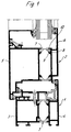
- FIGS. 2 to 8 Exemplary embodiments of the heat-insulated composite profile according to the invention are shown in FIGS. 2 to 8, while FIG. 1 shows a known embodiment of a heat-insulated composite profile in a shear-resistant composite of the individual parts.
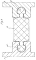
- a window is shown in which both the frame 1 and the sash 2 is constructed of thermally insulated composite profiles, each consist of metal profiles 3.4 and 5.6, which are interconnected by insulating strips 7 made of plastic.
- the edge strips of the insulating strips 8 engage in grooves in the metal profiles 3, 4, 5, 6, 5, which are delimited by metal strips 9, 10.
- the webs 10 are formed after inserting the edge strips 8 in the grooves of the metal profiles on the insulating strips, so that there is a bond between the insulating strips 7 and the metal profiles, which also ensures a transverse tensile strength in addition to the shear strength in the longitudinal direction of the composite profile. Additional means to increase shear strength have been described above.
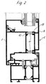
- the insulating strip 11 is designed in the casement 2 according to FIG Metal profile 5 is connected, while on the opposite long side has a guide arm 13 which is slidably mounted in an undercut groove of the outer metal profile 6.
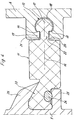
- the insulating strip 11 can be designed in accordance with FIG. 4, which shows the insulating strip on an enlarged scale.
- the sliding guide between the insulating strip 11 and the metal profile 6 has guide surfaces 14, 15 which run perpendicular or approximately perpendicular to the central axis 16 of the insulating strip 11.
- the deviation from perpendicularity can be in the range of ⁇ 20 °.
- the guide surfaces 14, 15 result in a clear, dimensional assignment of the insulating strip to the metal profile 6, so that the play required for the sliding guide between a cylindrical guide part 17 of the guide arm 13 and the undercut guide groove 18 is ensured.
- edge strips 19, 20 delimit a longitudinal opening 21 of the guide groove, through which a web 22 of the guide arm 13 extends, which is integral with the guide part 17.
- the guide arm can have any geometric shape in cross-section, provided that it is ensured that the play required for the sliding guide between the guide arm and the walls of the undercut groove of the metal profile is guaranteed.
- the edge strip 23 of the insulating strip 11 provided on the side opposite the guide arm 13 is shear-resistant in the receiving groove of the metal profile 5 fixed.
- a wire 24, which can be equipped with a surface structure, is in the receiving groove of the metal profile and partially embedded in the edge strip 23 of the insulating strip 11. Due to the shaping of the metal web 25 on the wire 24 or on the edge strip 23, the shear-resistant bond between the metal profile 5 and the insulating strip 11 is created in cooperation with the abutment web 26.
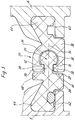
- the insulating strip 27, which connects the metal profiles 5 and 6 to one another in accordance with FIG. 3, is formed in two parts. It is composed of the insulating strip part 28, which is provided with a guide bracket 29, and the insulating strip part 30, which has an undercut groove 31 for the guide bracket 29.
- guide surfaces 32 and 33 are provided for the sliding guide, which extend perpendicularly or approximately perpendicularly to the central longitudinal axis 34.
- the guide arm 29 also has, in addition to the cylindrical guide part 35, a web 36 which extends through a longitudinal opening 37 of the undercut guide groove 31, edge strips 38 and 39 delimiting the longitudinal opening 37.
- the insulating strip part 28 is equipped with stop surfaces 40 and 41.
- the fastening feet 44 and 45 of the insulating strip parts engaging in the receiving grooves 42, 43 of the metal profiles 5, 6 are connected to the metal profiles 5 and 6 in a shear-resistant manner.
- FIG. 6 and 7 show exemplary embodiments in which the insulating strips 46 and 47 are fixed relative to the metal profiles 5 and 6 on both longitudinal sides via slide guides.
- the insulating strip 46 is equipped with guide brackets 48 which correspond in terms of space and function to the guide brackets 13 according to FIG. 4 and to the guide bracket 29 according to FIG. 5.
- the guide arms 49 of the insulating strip 47 are trapezoidal. In the case of other geometric cross sections of the guide arm as well, it must be ensured that the play required for the sliding guide is given between the guide arm and the associated undercut groove of the metal profile.
- Thermally insulated composite profiles can also be used for the frame or post profiles, in the case of which in the sense of the invention in a longitudinal connection area the shear strength between the connected components is low, goes to zero or there is a sliding guide.
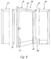
- FIG. 8 shows a door 50 which consists of a wing 51 and a frame 52. If the frame 52 is fixed in the masonry or on another construction, the bending stresses which occur are introduced into the masonry or into the construction mentioned via the fastening means. A bend does not occur.
- the heat-insulated composite profile according to the invention is used only for the production of the vertical door frame spars 53, 54. Due to the corner connection of these frame spars with the upper horizontal casement frame spar 55, the profile assembly according to the invention of the vertical frame spars 53, 54 is provided with a fixed point in the U-shaped frame. The longitudinal expansion of the metal profiles of the vertical bars, which occurs due to a temperature difference, can thus take place freely towards the underside of the U-shaped door frame.
- the upper horizontal door frame spar 55 can thus be implemented using conventional, shear-resistant composite technology.
- the frame 52 of this door is provided with side parts 56, 57, then it may be necessary to manufacture the vertical frame spars 58, 59 from heat-insulated composite profiles according to the invention, in which a longitudinal connection area between the connected components the shear strength is low, approaches zero or there is a sliding guide.
Abstract
Description
- Die Erfindung bezieht sich auf ein wärmegedämmtes Verbundprofil für Türen, Fenster oder Fassaden, bestehend aus Metallprofilen und mindestens einer zwischen den Metallprofilen angeordneten und mit den Metallprofilen an den Längsrändern verbundenen, vorzugsweise aus Kunststoff gefertigten Isolierleiste.
- Es ist bekannt, die Isolierleisten an ihren Längsrändern in hinterschnittenen Nuten der Metallprofile durch Anformen eines Metallsteges kraftschlüssig festzulegen. Bereits durch diesen Kraftschluß tritt aufgrund der Reibpaarung zwischen der Isolierleiste aus Kunststoff und den Metallprofilen eine Schubfestigkeit auf, die durch weitere Maßnahmen, wie reibwerterhöhende Beschichtungen, Verzahnungen innerhalb der Nutflächen oder durch mindestens einen zwischen dem anzuformenden Metallsteg und der Isolierleiste eingelegten verzahnten Draht erhöht werden kann.
- Diese Schubfestigkeit der Verbundprofile bewirkt bei den im Metallbau verwendeten Riegel-Pfosten-Konstruktionen ein höheres, wirksames Trägheitsmoment für die statischen Belastungsfälle.
- Daneben gibt es andere Verbundprofilsysteme, bei denen die Isolierleistenfixierung mittels mechanischer Spreizelemente oder mittels aufblähender Schäume und Kleber gesichert wird.
- Der Kraftschluß bzw. der Formschluß in Längsrichtung zwischen den Isolierleisten und den Metallprofilen der Verbundprofile bewirkt beim Angriff von statischen oder dynamischen Lasten, wie z.B. vom Wind erzeugten Sog- und Druckkräften, die Aufnahme von erhöhten Schubkräften und damit eine Verringerung der Durchbiegungen im statischen oder dynamischen Lastfall gegenüber der Addition der Einzelträgheitsmomente der zu einem Verbundprofil zusammengeführten Einzelprofile.
- Dieser Profilverbund wird als "schubfester Verbund" bezeichnet.
- Die Isolierleisten bilden zwischen den Metallprofilen eine thermische Trennebene, die den Wärmefluß von dem einen Metallprofil zum anderen auf ein Minimum begrenzt.
- Werden nun solche Profile mit schubfestem Verbund einseitig einer Temperaturerhöhung ausgesetzt, so ergibt sich aufgrund der Längenausdehnung des erwärmten Metallprofils eine Schubspannung zwischen den Bauteilen des Verbundprofils, die aufgrund der Schubfestigkeit des Verbundes sich in einer Durchbiegung des Verbundprofiles auswirkt.
- Wärmequellen sind z.B. Temperaturdifferenzen zwischen der Rauminnenseite und der Außenluft (Winterbetrieb) oder die Sonneneintrahlungen auf der Außenseite (Sommerbetrieb) und die damit verbundene Aufheizung der Außenseite durch Absorption der Sonnenenergie. Die entstehende Formänderung des Verbundprofils wirkt sich immer als Wölbung zur wärmeren Seite hin aus und beeinträchtigt die Funktion des Fensters bzw. der Tür, deren Rahmen aus dem Verbundprofil gefertigt wurden.
- Inbesondere bei relativ langen Rahmenholmen, wie z.B. bei den vertikalen Rahmenholmen von Türen, wirkt sich die infolge einseitiger Erwärmung entstehende Durchbiegung ungünstig auf die Dichtigkeit und auf die Schließfunktion der Schlösser aus. Dies trifft bei einem einfachen Mittelschloß als auch bei einer Mehrfachverriegelung zu, wobei es zum Versagen der Schließfunktion kommen kann.
- Bei Temperaturdifferenzen von 50 bis 60 °C infolge der Sonneneinstrahlung auf dunkle Oberflächen, sind die Durchbiegungen z.T. so groß, daß auch die Ausgleichswirkung der vorgesehenen Dichtungssysteme den entstehenden Spalt nicht mehr verschließen kann.
- Die Durchbiegung, hervorgerufen durch Temperaturdifferenzen zwischen dem äußeren und dem inneren Metallprofil des Verbundprofiles, bewirkt auch, daß das vorgesehene Schloß einer Tür unter Spannung gerät.
- Bei heute üblichen Mehrfachverriegelungen tritt diese Spannung mindestens an einem der Schlösser auf. Diese Spannungen bewirken, daß entweder die Tür nicht mehr ordnungsgemäß verschlossen oder mittels des Schlüssels nicht mehr geöffnet werden kann.
- Der Erfindung liegt die Aufgabe zugrunde, ein wärmegedämmtes Verbundprofil der eingangs genannten Art so zu gestalten, daß die unter wechselnden Temperaturbelastungen auftretende Längenänderung des einen Metallprofils nicht über Schubspannungen auf das zweite Metallprofil übertragen wird.
- Diese Aufgabe wird erfindungsgemäß dadurch gelöst, daß in einem Längsverbindungsbereich zwischen den verbundenen Bauteilen des wärmegedämmten Verbundprofils die Schubfestigkeit gering ist, gegen null geht oder eine Gleitführung vorhanden ist.
- Hierdurch können unterschiedliche Längenänderungen der Metallprofile des wärmegedämmten Verbundprofils aufgrund unterschiedlicher Temperaturbelastungen unabhängig voneinander vorgenommen werden.
- Der Längsverbindungsbereich mit geringer Schubfestigkeit, mit einer Schubfestigkeit, die gegen null geht, oder der mit einer Gleitführung versehen ist, kann der Verbindungsbereich zwischen einem Längsrand einer Isolierleiste und dem zugeordneten Metallprofil sein. Es ist jedoch auch möglich, die Isolierleiste zweiteilig auszubilden und den Längsverbindungsbereich zwischen diesen beiden Isolierleistenteilen mit geringer Schubfestigkeit, mit einer Schubfestigkeit, die gegen null geht, auszurüsten oder mit einer Gleitführung zu versehen.
- Weitere Merkmale der Erfindung ergeben sich aus den Unteransprüchen.
- Ausführungsbeispiele des erfindungsgemäßen, wärmegedämmten Verbundprofils sind in den Figuren 2 bis 8 dargestellt, während die Fig. 1 eine bekannte Ausführung eines wärmegedämmten Verbundprofils in schubfestem Verbund der Einzelteile zeigt.
- In der Fig. 1 ist ein Fenster dargestellt, bei dem sowohl der Blendrahmen 1 als auch der Flügelrahmen 2 aus wärmegedämmten Verbundprofilen aufgebaut ist, die jeweils aus Metallprofilen 3,4 bzw. 5,6 bestehen, die untereinander durch Isolierleisten 7 aus Kunststoff verbunden sind. Die Isolierleisten greifen mit ihren Randleisten 8 in Aufnahmenuten der Metallprofile 3,4;5,6 ein, die durch Metallstege 9,10 begrenzt werden. Die Stege 10 werden nach dem Einlegen der Randleisten 8 in die Aufnahmenuten der Metallprofile an die Isolierleisten angeformt, so daß sich zwischen den Isolierleisten 7 und den Metallprofilen ein Verbund ergibt, der zusätzlich zu der Schubfestigkeit in Längsrichtung des Verbundprofils auch eine Querzugfestigkeit gewährleistet. Zusätzliche Mittel zur Erhöhung der Schubfestigkeit wurden im vorhergehenden beschrieben.
- Um die nachteiligen, unterschiedlichen Verformungen der schubfest miteinander verbundenen Metallprofile 3,4 bzw. 5,6 unter unterschiedlichen Wärmebelastungen zu vermeiden, wird bei dem Flügelrahmen 2 nach der Fig. 2 die Isolierleiste 11 so gestaltet, daß sie mit einer Längsrandleiste 12 schubfest mit dem Metallprofil 5 verbunden ist, während sie auf der gegenüberliegenden Längsseite einen Führungsausleger 13 aufweist, der in einer hinterschnittenen Nut des außenliegenden Metallprofils 6 gleitbar gelagert ist.
- Die Isolierleiste 11 kann entsprechend der Fig. 4 gestaltet sein, die die Isolierleiste in vergrößertem Maßstab zeigt. Die Gleitführung zwischen der Isolierleiste 11 und dem Metallprofil 6 weist Führungsflächen 14,15 auf, die senkrecht oder annähernd senkrecht zur Mittelachse 16 der Isolierleiste 11 verlaufen. Die Abweichung von der Rechtwinkligkeit kann im Bereich von ± 20° liegen.
- Durch die Führungsflächen 14,15 ergibt sich eine eindeutige, maßliche Zuordnung der Isolierleiste zu dem Metallprofil 6, so daß das für die Gleitführung erforderliche Spiel zwischen einem zylindenförmigen Führungsteil 17 des Führungsauslegers 13 und der hinterschnittenen Führungsnut 18 gewährleistet ist.
- Bei dem Ausführungsbeispiel nach der Fig. 4 begrenzen Randleisten 19,20 eine Längsöffnung 21 der Führungsnut, durch die sich ein Steg 22 des Führungsauslegers 13 erstreckt, der mit dem Führungsteil 17 einstückig ist.
- Der Führungsausleger kann im Querschnitt eine beliebige geometrische Form aufweisen, sofern gewährleistet ist, daß das für die Gleitführung erforderliche Spiel zwischen dem Führungsausleger und den Wandungen der hinterschnittenen Nut des Metallprofils gewährleistet ist.
- Die an der dem Führungsausleger 13 gegenüberliegenden Seite vorgesehene Randleiste 23 der Isolierleiste 11 ist schubfest in der Aufnahmenut des Metallprofils 5 festgelegt. Zur Erhöhung der Schubfestigkeit ist in der Aufnahmenut des Metallprofils und teilweise eingebettet in der Randleiste 23 der Isolierleiste 11 ein Draht 24, der mit einer Oberflächenstrukturierung ausgerüstet sein kann. Durch die Anformung des Metallsteges 25 an den Draht 24 bzw. an die Randleiste 23 wird im Zusammenwirken mit dem Widerlagersteg 26 der schubfeste Verbund zwischen dem Metallprofil 5 und der Isolierleiste 11 geschaffen.
- Bei dem Ausführungsbeispiel nach der Fig. 5 ist die Isolierleiste 27, die entsprechend der Fig. 3 die Metallprofile 5 und 6 miteinander verbindet, zweiteilig ausgebildet. Sie setzt sich aus dem Isolierleistenteil 28, das mit einem Führungsausleger 29 versehen ist, und aus dem Isolierleistenteil 30 zusammen, das eine hinterschnittene Nut 31 für den Führungsausleger 29 aufweist.
- Auch bei diesem Ausführungsbeispiel sind für die Gleitführung Führungsflächen 32 und 33 vorgesehen, die sich senkrecht oder annähernd senkrecht zu der Mittellängsachse 34 erstrecken. Der Führungsausleger 29 weist auch bei diesem Ausführungsbeispiel zusätzlich zu dem zylinderförmigen Führungsteil 35 einen Steg 36 auf, der sich durch eine Längsöffnung 37 der hinterschnittenen Führungsnut 31 erstreckt, wobei Randleisten 38 und 39 die Längsöffnung 37 begrenzen. Das Isolierleistenteil 28 ist mit Anschlagflächen 40 und 41 ausgerüstet.
- Die in die Aufnahmenuten 42,43 der Metallprofile 5,6 eingreifenden Befestigungsfüße 44 und 45 der Isolierleistenteile sind schubfest mit den Metallprofilen 5 und 6 verbunden.
- Die Fig. 6 und 7 zeigen Ausführungsbeispiele, in denen die Isolierleisten 46 und 47 gegenüber den Metallprofilen 5 und 6 an beiden Längsseiten über Gleitführungen festgelegt sind. Die Isolierleiste 46 ist bei dem Ausführungsbeispiel mit Führungsauslegern 48 ausgerüstet, die mit den Führungsauslegern 13 nach der Fig. 4 und mit dem Führungsausleger 29 nach der Fig. 5 in der Raumform und in der Funktion übereinstimmen.
- Bei dem Ausführungsbeispiel nach der Fig. 7 sind die Führungsausleger 49 der Isolierleiste 47 trapezförmig ausgebildet. Auch bei anderen geometrischen Querschnitten der Führungsausleger muß gewährleistet werden, daß das für die Gleitführung erforderliche Spiel zwischen dem Führungsausleger und der zugeordneten hinterschnittenen Nut des Metallprofils gegeben ist.
- Auch bei den Rahmen- bzw. Pfostenprofilen können wärmegedämmte Verbundprofile eingesetzt werden, bei denen im Sinne der Erfindung in einem Längsverbindungsbereich zwischen den verbundenen Bauteilen die Schubfestigkeit gering ist, gegen null geht oder eine Gleitführung vorhanden ist.
- Die Fig. 8 zeigt eine Tür 50, die aus einem Flügel 51 und einem Blendrahmen 52 besteht. Wird der Blendrahmen 52 im Mauerwerk oder an einer sonstigen Konstruktion festgelegt, so werden über die Befestigungsmittel die auftretenden Biegespannungen ins Mauerwerk oder in die genannten Konstruktion eingeleitet. Eine Biegung tritt nicht auf. In diesem Fall wird das erfindungsgemäße wärmegedämmte Verbundprofil lediglich für die Herstellung der senkrechten Türrahmenholme 53,54 verwendet. Durch die Eckverbindung dieser Rahmenholme mit dem oberen waagerechten Flügelrahmenholm 55 ist der erfindungsgemäße Profilverbund der senkrechten Rahmenholme 53,54 im U-förmigen Rahmen mit einem Festpunkt versehen. Die aufgrund einer Temperaturdifferenz zustande kommende Längenausdehnung der Metallprofile der vertikalen Holme kann somit frei zur Unterseite des U-förmigen Türrahmens erfolgen. Der obere waagerechte Türrahmenholm 55 kann somit in herkömmlicher, schubfester Verbundtechnik ausgeführt sein.
- Ist der Blendrahmen 52 dieser Tür, jedoch wie in der Fig. 8 zusätzlich aufgezeigt, mit Seitenteilen 56,57 versehen, so kann es erforderlich werden, die senkrechten Blendrahmenholme 58,59 aus erfindungsgemäßen, wärmegedämmten Verbundprofilen zu fertigen, bei denen in einem Längsverbindungsbereich zwischen den verbundenen Bauteilen die Schubfestigkeit gering ist, gegen null geht oder eine Gleitführung vorhanden ist.
-
- 1
- Blendrahmen
- 2
- Blendrahmen
- 2
- Flügelrahmen
- 3/4
- Metallprofil
- 5
- Metallprofil
- 6
- Metallprofil
- 7
- Isolierleiste
- 8
- Randleiste
- 9/10
- Metallsteg
- 11
- Isolierleiste
- 13
- Führungsausleger
- 14/15
- Führungsflächen
- 16
- Mittelachse
- 17
- Führungsteil
- 18
- Führungsnut
- 19/20
- Randleiste
- 21
- Längsöffnung
- 22
- Steg
- 23
- Randleiste
- 24
- Draht
- 25
- Metallsteg
- 26
- Widerlagersteg
- 27
- Isolierleiste
- 28
- Isolierleistenteil
- 29
- Führungsausleger
- 30
- Isolierleistenteil
- 31
- Nut
- 32/33
- Führungsfläche
- 34
- Mittellängsachse
- 35
- Führungsteil
- 36
- Steg
- 37
- Längsöffnung
- 38/39
- Randleiste
- 40/41
- Anschlagfläche
- 42/43
- Aufnahmenut
- 44/45
- Befestigungsfuß
- 46/47
- Isolierleiste
- 48/49
- Führungsausleger
- 50
- Tür
- 51
- Flügel
- 53/54
- Türrahmenholm
- 55
- Flügelrahmenholm
- 56/57
- Seitenteil
- 58/59
- Blendrahmenholm
Claims (15)
- Wärmegedämmtes Verbundprofil für Türen, Fenster oder Fassaden, bestehend aus Metallprofilen (3,4;5,6) und mindestens einer zwischen den Metallprofilen angeordneten und mit den Metallprofilen an den Längsrändern verbundenen, vorzugsweise aus Kunststoff gefertigten Isolierleiste (7,11,27,46,47), dadurch gekennzeichnet, daß zur Vermeidung einer Ausbiegung durch ungleichmäßige Erwärmung der Metallprofile in einem Längsverbindungsbereich zwischen den verbundenen Bauteilen die Schubfestigkeit gering ist, gegen null geht oder eine Gleitführung vorhanden ist.
- Wärmegedämmtes Verbundprofil nach Anspruch 1, dadurch gekennzeichnet, daß in sämtlichen Längsverbindungsbereichen zwischen dem außenliegenden Metallprofil (6) und den Isolierleisten (11) die Schubfestigkeit gering ist, gegen null geht oder eine Gleitführung vorhanden ist und die Längsverbindungsbereiche zwischen dem innenliegenden Metallprofil (5) und den Isolierleisten (11) eine hohe Schubfestigkeit aufweisen (Fig. 2).
- Wärmegedämmtes Verbundprofil nach Anspruch 1, dadurch gekennzeichnet, daß in sämtlichen Längsverbindungsbereichen zwischen dem innenliegenden Metallprofil (5) und den Isolierleisten (11) die Schubfestigkeit gering ist, gegen null geht oder eine Gleitführung vorhanden ist und die Längsverbindungsbereiche zwischen dem außenliegenden Metallprofil (6) und den Isolierleisten (11) eine hohe Schubfestigkeit aufweisen.
- Wärmegedämmtes Verbundprofil nach Anspruch 1, dadurch gekennzeichnet, daß in sämtlichen Längsverbindungsbereichen zwischen dem außenliegenden, dem innenliegenden Metallprofil (5,6) und Isolierleisten (46,47) Gleitführungen vorgesehen sind (Fig. 6,7).
- Wärmegedämmtes Verbundprofil nach einem der Ansprüche 1 bis 4, dadurch gekennzeichnet, daß die Gleitführungen Führungsflächen (14,15;32,33) aufweisen, die senkrecht oder annähernd senkrecht zur Mittelachse (16,36) der Isolierleiste (11,27) verlaufen.
- Wärmegedämmtes Verbundprofil nach Anspruch 5, dadurch gekennzeichnet, daß die Abweichung von der Rechtwinkligkeit im Bereich von ± 20° liegt.
- Wärmegedämmtes Verbundprofil nach einem der Ansprüche 1 bis 6, dadurch gekennzeichnet, daß im Bereich der Gleitführungen ein Führungsausleger (13) der Isolierleiste (11) oder der Isolierleisten in einer Führungsnut des zugeordneten Metallprofils (6) mit entsprechendem Spiel gelagert ist bzw. sind.
- Wärmegedämmtes Verbundprofil nach Anspruch 7, dadurch gekennzeichnet, daß die Führungsnut (18) als hinterschnittene Nut ausgebildet ist, die an der der Isolierleiste zugewandten Seite durch Randleisten (19,20) des Metallprofils begrenzt ist, die ihrerseits eine Längsöffnung (21) des Metallprofils begrenzen, durch die sich ein Steg (22) des Führungsauslegers (13) erstreckt, der mit einem zylinderförmigen, die Randleisten hintergreifenden Führungsteil (17) einstückig ist.
- Wärmegedämmtes Verbundprofil nach Anspruch 7, dadurch gekennzeichnet, daß die Führungsnut hinterschnitten ist, einen trapezförmigen Querschnitt aufweist und der Führungsausleger der Isolierleiste oder der Isolierleisten im Querschnitt trapezförmig ausgebildet ist.
- Wärmegedämmtes Verbundprofil nach Anspruch 1, dadurch gekennzeichnet, daß die Isolierleiste (27) oder die parallel zueinander angeordneten Isolierleisten zweiteilig ausgebildet sind, jedes Isolierleistenteil (28,30) mit dem zugeordneten Metallprofil (5,6) schubfest verbunden ist und die mittige Verbindung zwischen den zwei Isolierleistenteilen als Gleitführung ausgeführt ist.
- Wärmegedämmtes Verbundprofil nach Anspruch 10, dadurch gekennzeichnet, daß das eine Isolierleistenteil (30) mit einer hinterschnittenen Führungsnut (31) und das Isolierleistenteil (28) einen mit Spiel in der Führungsnut gelagerten Führungsausleger (29) aufweist.
- Wärmegedämmtes Verbundprofil nach Anspruch 11, dadurch gekennzeichnet, daß die hinterschnittene Nut (31) eine durch Randleisten (38,39) begrenzte seitliche Längsöffnung aufweist, durch die sich ein Steg (36) des Führungsauslegers erstreckt, der mit einem zylinderförmigen Führungsteile (35) einstückig ist.
- Wärmegedämmtes Verbundprofil nach Anspruch 12, dadurch gekennzeichnet, daß das mit dem Führungsausleger (29) ausgerüstete Isolierleistenteil parallel zu den Randleisten (38,39) verlaufende Anschlagflächen (40,41) aufweist.
- Wärmegedämmtes Verbundprofil für eine Tür mit U-förmigem Flügelrahmen, dessen vertikale Holme unten durch ein Sockelblech verbunden sind, dadurch gekennzeichnet, daß die vertikalen Holme aus einem Verbundprofil nach einem der Ansprüche 1 bis 13 bestehen und der obere waagerechte Holm in schubfester Verbundtechnik ausgeführt.
- Wärmegedämmtes Verbundprofil für eine Tür nach Anspruch 14 mit U-förmigen Blendrahmen, an dessen vertikalen Holmen Seitenteile mit L-förmigem Rahmen befestigt sind, dadurch gekennzeichnet, daß die vertikalen Holme des Blendrahmens aus einem wärmegedämmten Verbundprofil nach einem der Ansprüche 1 bis 13 bestehen und der obere waagerechte Holm des Blendrahmens in schubfester Verbundtechnik ausgeführt ist.
Priority Applications (1)
| Application Number | Priority Date | Filing Date | Title |
|---|---|---|---|
| SI9730177T SI0829609T1 (en) | 1996-09-17 | 1997-07-17 | Heat-insulating compound profile for doors, windows or facades |
Applications Claiming Priority (2)
| Application Number | Priority Date | Filing Date | Title |
|---|---|---|---|
| DE19637858A DE19637858A1 (de) | 1996-09-17 | 1996-09-17 | Wärmegedämmtes Verbundprofil für Türen, Fenster oder Fassaden |
| DE19637858 | 1996-09-17 |
Publications (3)
| Publication Number | Publication Date |
|---|---|
| EP0829609A2 true EP0829609A2 (de) | 1998-03-18 |
| EP0829609A3 EP0829609A3 (de) | 1998-11-18 |
| EP0829609B1 EP0829609B1 (de) | 2001-05-09 |
Family
ID=7805886
Family Applications (1)
| Application Number | Title | Priority Date | Filing Date |
|---|---|---|---|
| EP97112230A Expired - Lifetime EP0829609B1 (de) | 1996-09-17 | 1997-07-17 | Wärmegedämmtes Verbundprofil für Türen, Fenster oder Fassaden |
Country Status (26)
| Country | Link |
|---|---|
| US (1) | US6035600A (de) |
| EP (1) | EP0829609B1 (de) |
| JP (1) | JP4155610B2 (de) |
| KR (1) | KR100502028B1 (de) |
| CN (1) | CN1312373C (de) |
| AT (1) | ATE201083T1 (de) |
| BA (1) | BA97255A (de) |
| BG (1) | BG62821B1 (de) |
| CA (1) | CA2215591C (de) |
| CZ (1) | CZ293569B6 (de) |
| DE (3) | DE29623019U1 (de) |
| DK (1) | DK0829609T3 (de) |
| EE (1) | EE03532B1 (de) |
| ES (1) | ES2156323T3 (de) |
| GR (1) | GR3036194T3 (de) |
| HR (1) | HRP970500B1 (de) |
| HU (1) | HU221520B (de) |
| NO (1) | NO319731B1 (de) |
| PT (1) | PT829609E (de) |
| RS (1) | RS49917B (de) |
| RU (1) | RU2183243C2 (de) |
| SI (1) | SI0829609T1 (de) |
| SK (1) | SK285095B6 (de) |
| TR (1) | TR199700820A2 (de) |
| TW (1) | TW357222B (de) |
| UA (1) | UA46007C2 (de) |
Cited By (19)
| Publication number | Priority date | Publication date | Assignee | Title |
|---|---|---|---|---|
| EP1002924A2 (de) * | 1998-11-18 | 2000-05-24 | Norsk Hydro Asa | Wärmegedämmtes Verbundprofil, insbesondere für Fenster, Türen, Fassaden und dergleichen |
| EP1004739A3 (de) * | 1998-11-26 | 2000-11-15 | Johann Henkenjohann | Isolierverbund für Aluminium-Profile |
| EP1503023A2 (de) * | 2003-08-01 | 2005-02-02 | Seitz GmbH & Co. KG | Verfahren zum Herstellen eines Rahmens insbesondere für ein Fenster oder eine Tür an einem Wohnwagen oder einem Reisemobil |
| US7913470B2 (en) | 2007-04-02 | 2011-03-29 | Technoform Caprano Und Brunnhofer Gmbh & Co. Kg | Insulating strip for supporting a composite structure |
| EP2325431A2 (de) | 2009-11-21 | 2011-05-25 | Norsk Hydro Asa | Verfahren zur Herstellung eines wärmegedämmten Verbundprofils |
| DE102014106226A1 (de) | 2014-05-05 | 2015-11-05 | SCHÜCO International KG | Verbundprofil für Türen, Fenster oder Fassadenelemente |
| EP2942468A1 (de) | 2014-05-05 | 2015-11-11 | SCHÜCO International KG | Verbundprofil für türen, fenster oder fassadenelemente |
| WO2015169668A1 (de) * | 2014-05-05 | 2015-11-12 | SCHÜCO International KG | Verbundprofil für türen, fenster oder fassadenelemente |
| WO2015169670A1 (de) * | 2014-05-05 | 2015-11-12 | SCHÜCO International KG | Verbundprofil für türen, fenster oder fassadenelemente |
| DE102014112131A1 (de) | 2014-08-25 | 2016-02-25 | SCHÜCO International KG | Verbundprofil für Türen, Fenster oder Fassadenelemente |
| DE102014112091A1 (de) | 2014-08-25 | 2016-02-25 | SCHÜCO International KG | Verbundprofil für Türen, Fenster oder Fassadenelemente |
| DE102014112128A1 (de) | 2014-08-25 | 2016-02-25 | SCHÜCO International KG | Verbundprofil für Türen, Fenster oder Fassadenelemente |
| DE102014112145A1 (de) | 2014-08-25 | 2016-02-25 | SCHÜCO International KG | Verbundprofil für Türen, Fenster oder Fassadenelemente |
| EP3015635A1 (de) | 2014-10-29 | 2016-05-04 | SCHÜCO International KG | Verbundprofil für türen, fenster oder fassadenelemente |
| EP3246505A1 (de) | 2016-05-17 | 2017-11-22 | SCHÜCO International KG | Verbundprofil für türen, fenster oder fassadenelemente |
| WO2020152180A1 (de) * | 2019-01-21 | 2020-07-30 | Dormakaba Deutschland Gmbh | Profilanordnung |
| DE102019110178A1 (de) * | 2019-04-17 | 2020-10-22 | HUECK System GmbH & Co. KG | Isoliersteg |
| BE1027906A1 (fr) | 2019-12-23 | 2021-07-16 | Van Beveren Sa | Ouvrant de porte ou de fenêtre composé de profilés composites et porte ou fenêtre comprenant un tel ouvrant |
| US11414917B2 (en) | 2016-10-13 | 2022-08-16 | Ensinger Gmbh | Profiled plastic section for a metal/plastic composite profiled section |
Families Citing this family (40)
| Publication number | Priority date | Publication date | Assignee | Title |
|---|---|---|---|---|
| DE19956415C1 (de) * | 1999-11-24 | 2001-03-01 | Caprano & Brunnhofer | Isolierprofil für Türrahmen, Fensterrahmen oder dergleichen Verbundteile |
| DE10015986C2 (de) * | 2000-03-31 | 2002-08-01 | Schueco Int Kg | Verbundprofil und Verfahren zur Herstellung eines Verbundprofils |
| DE10331210A1 (de) * | 2003-07-10 | 2005-03-10 | Oswald Kothgasner | Verbundprofil |
| US20080193771A1 (en) * | 2004-03-04 | 2008-08-14 | Fiberline A/S | Method of Preventing or Reducing Temperature Gradient Caused Bending of a Structural Element |
| DE102004038868A1 (de) * | 2004-08-10 | 2006-02-23 | Hydro Building Systems Gmbh | Wärmegedämmtes Profil für Fenster, Türen, Fassadenelemente und dergleichen |
| US20070074479A1 (en) * | 2005-08-31 | 2007-04-05 | Vie Giant Enterprise Co., Ltd. | Metal strengthened structure |
| DE202007004804U1 (de) | 2007-03-30 | 2007-06-14 | SCHÜCO International KG | Isolierleiste für ein wärmegedämmtes Verbundprofil für Türen, Fenster oder Fassaden |
| DE102007039009A1 (de) * | 2007-08-17 | 2009-02-19 | Rehau Ag + Co | Rahmen-Baugruppe sowie Kunststoff-Profilrahmen hierfür |
| ITMI20071932A1 (it) * | 2007-10-05 | 2009-04-06 | Norsk Hydro As | Semiguscio per realizzare serramenti a taglio termico o simili, relativo profilato e relativo processo di assemblaggio |
| EP2088276B1 (de) | 2008-02-09 | 2017-05-24 | HUECK GmbH & Co. KG | Isolierprofil-Anordnung zwischen Blend- und Flügelrahmen eines Fensters oder einer Tür |
| EP2136024B1 (de) * | 2008-06-18 | 2011-11-09 | Technoform Bautec Holding GmbH | Verbundprofil für Fenster-, Türen-, oder Fassadenelement mit vorbestimmten Brandschutzeigenschaften und Isoliersteg für ein Verbundprofil mit Brandschutzeigenschaften |
| KR101044784B1 (ko) * | 2008-07-04 | 2011-06-29 | 김승현 | 건축물 외벽용 창호장치 |
| DE102008047331C5 (de) * | 2008-09-16 | 2016-09-08 | Hueck Gmbh & Co. Kg | Verfahren zur Herstellung eines Verbundprofils |
| WO2010085174A1 (ru) * | 2009-01-21 | 2010-07-29 | Закрытое Акционерное Общество "Т.Б.М." | Узловое соединение профилей распашной двери |
| WO2010085173A1 (ru) * | 2009-01-21 | 2010-07-29 | Закрытое Акционерное Общество "Т.Б.М." | Система узловых соединений профилей окон (варианты) |
| WO2010085177A1 (ru) * | 2009-01-21 | 2010-07-29 | Закрытое Акционерное Общество "Т.Б.М." | Система узлового соединения профилей вставного окна |
| WO2010085171A1 (ru) * | 2009-01-21 | 2010-07-29 | Закрытое Акционерное Общество "Т.Б.М." | Система узловых соединений профилей окон (варианты) |
| IE86524B1 (en) | 2009-07-15 | 2015-04-08 | Architectural & Metal Systems Ltd | Insulated frame member |
| IT1399707B1 (it) * | 2010-04-26 | 2013-04-26 | Palladio Spa | Serramento a taglio termico naturale |
| BE1019368A3 (nl) | 2010-06-09 | 2012-06-05 | Reynaers Aluminium Nv | Samengesteld profiel. |
| EP2530230B1 (de) | 2011-05-30 | 2016-12-28 | Kawneer Aluminium Deutschland Inc. | Isoliersteg für Fenster- und Türrahmen |
| DE102013204693A1 (de) | 2012-03-19 | 2013-09-19 | Harald Schulz | Dämmsteg für wärmegedämmte Metall-Kunststoff-Verbundprofile mit über der Dämmsteglänge veränderlicher Schubtragfähigkeit sowie wärmegedämmtes Verbundprofil |
| CN102679137A (zh) * | 2012-05-05 | 2012-09-19 | 广亚铝业有限公司 | 一种单隔热条型材的穿接槽结构 |
| US9234380B2 (en) | 2013-03-13 | 2016-01-12 | Technoform Bautec North America, Inc. | Thermally insulating composite frame apparatus with slide-in thermal isolator and method for making same |
| US9115520B2 (en) * | 2013-05-17 | 2015-08-25 | Dynamic Hive, Inc. | Partition system and track support |
| DE102014112107A1 (de) | 2014-08-25 | 2016-02-25 | SCHÜCO International KG | Tür oder Fenster mit Brandschutzeigenschaften |
| DE102014012894A1 (de) * | 2014-08-30 | 2016-03-03 | Sapa Building Systems GmbH | Bauteil zum Einsatz in der Bautechnik und Gebäudetechnik |
| CN104633433A (zh) * | 2014-12-30 | 2015-05-20 | 潘茜茜 | 板材 |
| CN104565785A (zh) * | 2014-12-30 | 2015-04-29 | 潘茜茜 | 板材 |
| CN105987268A (zh) * | 2015-02-05 | 2016-10-05 | 王士兵 | 节能保温断桥铝合金型材 |
| US9328549B1 (en) | 2015-04-02 | 2016-05-03 | Special-Lite, Inc. | Frame with thermal barrier |
| DE102017100335A1 (de) * | 2016-02-29 | 2017-08-31 | SCHÜCO International KG | Tür, Fenster oder Fassadenelement sowie Beschlaganordnung für ein solches Element |
| US10829982B2 (en) * | 2016-10-06 | 2020-11-10 | Peerless Products, Inc. | Framing system |
| US10053241B2 (en) * | 2016-12-01 | 2018-08-21 | The Boeing Company | Systems and methods for multi-spacecraft distributed ascent |
| DE102017107684A1 (de) * | 2017-04-10 | 2018-10-11 | Ensinger Gmbh | Isolierprofil, insbesondere für die Herstellung von Fenster-, Türen- und Fassadenelementen, sowie Verfahren zu seiner Herstellung |
| ES2907245T3 (es) * | 2017-05-31 | 2022-04-22 | Technoform Bautec Holding Gmbh | Perfil para elemento de ventana, de puerta, de fachada y de revestimiento y método para su fabricación |
| CN107866034B (zh) * | 2017-11-30 | 2022-09-27 | 浙江正星健身器有限公司 | 一种跑步机的边条锁紧机构 |
| FR3099199B1 (fr) * | 2019-07-23 | 2022-02-11 | Groupe Liebot | Ouvrant pour une menuiserie destinée à équiper une baie de bâtiment |
| US11248412B2 (en) * | 2019-11-18 | 2022-02-15 | Rehme Custom Doors & Lighting, Inc. | Metallic fenestration systems with improved thermal performance and methods of manufacturing same |
| WO2021162643A1 (en) * | 2020-02-11 | 2021-08-19 | Pirnar, Trženje, Proizvodnja In Razvoj, D.O.O. | A frame, in particular door frame |
Citations (7)
| Publication number | Priority date | Publication date | Assignee | Title |
|---|---|---|---|---|
| DE1940791A1 (de) * | 1969-08-11 | 1971-02-25 | Keller Eberhard | Waermeisolierung fuer Fenster oder Tuerrahmen |
| FR2123311A1 (de) * | 1971-01-08 | 1972-09-08 | Hartmann & Co | |
| US4067163A (en) * | 1977-03-11 | 1978-01-10 | Hetman Frank W | Thermally insulated and connected window frame members and the method of making the same |
| DE3334332A1 (de) * | 1983-09-22 | 1985-04-04 | Julius & August Erbslöh GmbH & Co, 5600 Wuppertal | Verfahren und hohlkoerper zur herstellung einer gleitfuehrung zwischen zwei relativ zueinander beweglichen bauteilen |
| DE3418470A1 (de) * | 1984-05-18 | 1985-11-21 | W. Hartmann & Co (Gmbh & Co), 2000 Hamburg | Langgestrecktes verbundelement zur bildung von vorgefertigten gebaeudeteilen |
| DE3425135A1 (de) * | 1984-07-07 | 1986-01-16 | Julius & August Erbslöh GmbH + Co, 5620 Velbert | Waermegedaemmtes verbundprofil |
| EP0657612A1 (de) * | 1993-12-02 | 1995-06-14 | Lorenzo Diaz Maricurreina | Modularsystem zur Herstellung von Verglasungen |
Family Cites Families (16)
| Publication number | Priority date | Publication date | Assignee | Title |
|---|---|---|---|---|
| DE2137145A1 (de) * | 1971-07-24 | 1973-02-01 | Hartmann & Co W | Zusammengesetzte, waermedurchgangsunterbrechende metallrahmenprofilteile fuer tuer- und fensterkonstruktionen |
| DE2237245C3 (de) * | 1972-04-13 | 1979-10-11 | Goetz Metallbau Gmbh, 8360 Deggendorf | Isolationsprofil aus Kunststoff für ein Verbundprofil |
| US4115972A (en) * | 1976-05-24 | 1978-09-26 | Giovanni Varlonga | Fixed and movable frame fixtures for doors and windows |
| FR2363720A1 (fr) * | 1976-08-31 | 1978-03-31 | Hasselbacher Wilhelm | Bande de liaison pour deux pieces en metal |
| DE2755695C3 (de) * | 1977-12-14 | 1981-03-12 | Wieland-Werke Ag, 7900 Ulm | Wärmegedämmtes Verbundprofil für Fenster, Türen u.dgl. |
| DE2755697C3 (de) * | 1977-12-14 | 1980-09-25 | Wieland-Werke Ag, 7900 Ulm | Wärmegedämmtes Verbundprofil |
| DE7903259U1 (de) * | 1979-02-07 | 1979-06-13 | Schueco Heinz Schuermann Gmbh & Co, 4800 Bielefeld | Metall-profilstab |
| DE2908950A1 (de) * | 1979-03-07 | 1980-09-18 | Schuermann & Co Heinz | Verfahren zum herstellen eines waermegedaemmten tuerfluegels sowie tuerfluegelrahmen |
| DE8808116U1 (de) * | 1988-06-23 | 1989-10-26 | Metallbau Koller Ag, Muttenz, Ch | |
| DE8916016U1 (de) * | 1989-12-02 | 1993-02-11 | Schueco International Kg, 4800 Bielefeld, De | |
| JPH0799066B2 (ja) * | 1992-11-27 | 1995-10-25 | トステム株式会社 | 断熱サッシ |
| JPH0762949A (ja) * | 1993-08-31 | 1995-03-07 | Tateyama Alum Ind Co Ltd | 断熱複合型材 |
| JPH07305566A (ja) * | 1994-05-13 | 1995-11-21 | Sankyo Alum Ind Co Ltd | 断熱形材および断熱形材の接続方法 |
| DE4427682C2 (de) * | 1994-08-04 | 1996-12-12 | Ensinger Gmbh & Co | Verbundprofil für Rahmen von Fenstern, Türen, Fassadenelementen u. dgl. |
| JPH09235946A (ja) * | 1996-02-29 | 1997-09-09 | Ykk Architect Prod Kk | 断熱形材 |
| DE19613046C2 (de) * | 1996-04-01 | 1999-12-09 | Evg Bauprofil System Entwicklungs & Vermarktungsgesellschaft Mbh | Wärmeisolierender Verbundsteg |
-
1996
- 1996-09-17 DE DE29623019U patent/DE29623019U1/de not_active Expired - Lifetime
- 1996-09-17 DE DE19637858A patent/DE19637858A1/de not_active Withdrawn
-
1997
- 1997-07-17 DE DE59703498T patent/DE59703498D1/de not_active Expired - Lifetime
- 1997-07-17 DK DK97112230T patent/DK0829609T3/da active
- 1997-07-17 EP EP97112230A patent/EP0829609B1/de not_active Expired - Lifetime
- 1997-07-17 SI SI9730177T patent/SI0829609T1/xx unknown
- 1997-07-17 AT AT97112230T patent/ATE201083T1/de active
- 1997-07-17 PT PT97112230T patent/PT829609E/pt unknown
- 1997-07-17 ES ES97112230T patent/ES2156323T3/es not_active Expired - Lifetime
- 1997-08-19 TR TR97/00820A patent/TR199700820A2/xx unknown
- 1997-09-01 BG BG101871A patent/BG62821B1/bg active Active
- 1997-09-02 US US08/922,199 patent/US6035600A/en not_active Expired - Lifetime
- 1997-09-04 HU HU9701473A patent/HU221520B/hu not_active IP Right Cessation
- 1997-09-11 TW TW086113226A patent/TW357222B/zh active
- 1997-09-11 BA BA970255A patent/BA97255A/bs unknown
- 1997-09-12 SK SK1236-97A patent/SK285095B6/sk not_active IP Right Cessation
- 1997-09-12 UA UA97094587A patent/UA46007C2/uk unknown
- 1997-09-12 KR KR1019970047000A patent/KR100502028B1/ko not_active IP Right Cessation
- 1997-09-15 CZ CZ19972893A patent/CZ293569B6/cs not_active IP Right Cessation
- 1997-09-16 RS YUP-380/97A patent/RS49917B/sr unknown
- 1997-09-16 CA CA002215591A patent/CA2215591C/en not_active Expired - Fee Related
- 1997-09-16 NO NO19974272A patent/NO319731B1/no not_active IP Right Cessation
- 1997-09-16 EE EE9700171A patent/EE03532B1/xx not_active IP Right Cessation
- 1997-09-16 HR HR970500A patent/HRP970500B1/xx not_active IP Right Cessation
- 1997-09-16 CN CNB971184836A patent/CN1312373C/zh not_active Expired - Fee Related
- 1997-09-16 RU RU97115221/03A patent/RU2183243C2/ru not_active IP Right Cessation
- 1997-09-16 JP JP25086997A patent/JP4155610B2/ja not_active Expired - Fee Related
-
2001
- 2001-07-09 GR GR20010401042T patent/GR3036194T3/el unknown
Patent Citations (7)
| Publication number | Priority date | Publication date | Assignee | Title |
|---|---|---|---|---|
| DE1940791A1 (de) * | 1969-08-11 | 1971-02-25 | Keller Eberhard | Waermeisolierung fuer Fenster oder Tuerrahmen |
| FR2123311A1 (de) * | 1971-01-08 | 1972-09-08 | Hartmann & Co | |
| US4067163A (en) * | 1977-03-11 | 1978-01-10 | Hetman Frank W | Thermally insulated and connected window frame members and the method of making the same |
| DE3334332A1 (de) * | 1983-09-22 | 1985-04-04 | Julius & August Erbslöh GmbH & Co, 5600 Wuppertal | Verfahren und hohlkoerper zur herstellung einer gleitfuehrung zwischen zwei relativ zueinander beweglichen bauteilen |
| DE3418470A1 (de) * | 1984-05-18 | 1985-11-21 | W. Hartmann & Co (Gmbh & Co), 2000 Hamburg | Langgestrecktes verbundelement zur bildung von vorgefertigten gebaeudeteilen |
| DE3425135A1 (de) * | 1984-07-07 | 1986-01-16 | Julius & August Erbslöh GmbH + Co, 5620 Velbert | Waermegedaemmtes verbundprofil |
| EP0657612A1 (de) * | 1993-12-02 | 1995-06-14 | Lorenzo Diaz Maricurreina | Modularsystem zur Herstellung von Verglasungen |
Cited By (30)
| Publication number | Priority date | Publication date | Assignee | Title |
|---|---|---|---|---|
| EP1002924A2 (de) * | 1998-11-18 | 2000-05-24 | Norsk Hydro Asa | Wärmegedämmtes Verbundprofil, insbesondere für Fenster, Türen, Fassaden und dergleichen |
| EP1002924A3 (de) * | 1998-11-18 | 2000-09-20 | Norsk Hydro Asa | Wärmegedämmtes Verbundprofil, insbesondere für Fenster, Türen, Fassaden und dergleichen |
| EP1004739A3 (de) * | 1998-11-26 | 2000-11-15 | Johann Henkenjohann | Isolierverbund für Aluminium-Profile |
| EP1503023A2 (de) * | 2003-08-01 | 2005-02-02 | Seitz GmbH & Co. KG | Verfahren zum Herstellen eines Rahmens insbesondere für ein Fenster oder eine Tür an einem Wohnwagen oder einem Reisemobil |
| EP1503023A3 (de) * | 2003-08-01 | 2006-01-18 | Seitz GmbH & Co. KG | Verfahren zum Herstellen eines Rahmens insbesondere für ein Fenster oder eine Tür an einem Wohnwagen oder einem Reisemobil |
| US7913470B2 (en) | 2007-04-02 | 2011-03-29 | Technoform Caprano Und Brunnhofer Gmbh & Co. Kg | Insulating strip for supporting a composite structure |
| EP2325431A2 (de) | 2009-11-21 | 2011-05-25 | Norsk Hydro Asa | Verfahren zur Herstellung eines wärmegedämmten Verbundprofils |
| DE102009054178B3 (de) * | 2009-11-21 | 2011-06-01 | Norsk Hydro Asa | Verfahren zur Herstellung eines wärmegedämmten Verbundprofils |
| US9920568B2 (en) | 2014-05-05 | 2018-03-20 | SCHÜCO International KG | Composite profile for doors, windows or façade elements |
| EP2942468A1 (de) | 2014-05-05 | 2015-11-11 | SCHÜCO International KG | Verbundprofil für türen, fenster oder fassadenelemente |
| WO2015169668A1 (de) * | 2014-05-05 | 2015-11-12 | SCHÜCO International KG | Verbundprofil für türen, fenster oder fassadenelemente |
| WO2015169671A1 (de) * | 2014-05-05 | 2015-11-12 | SCHÜCO International KG | Verbundprofil für türen, fenster oder fassadenelemente |
| WO2015169670A1 (de) * | 2014-05-05 | 2015-11-12 | SCHÜCO International KG | Verbundprofil für türen, fenster oder fassadenelemente |
| DE102014106226A1 (de) | 2014-05-05 | 2015-11-05 | SCHÜCO International KG | Verbundprofil für Türen, Fenster oder Fassadenelemente |
| RU2695526C2 (ru) * | 2014-05-05 | 2019-07-23 | Шюко Интернациональ Кг | Составной профиль для дверей, окон или фасадных элементов |
| RU2694378C2 (ru) * | 2014-05-05 | 2019-07-12 | Шюко Интернациональ Кг | Составной профиль для дверей, окон или фасадных элементов |
| DE102014112128A1 (de) | 2014-08-25 | 2016-02-25 | SCHÜCO International KG | Verbundprofil für Türen, Fenster oder Fassadenelemente |
| DE102014112145A1 (de) | 2014-08-25 | 2016-02-25 | SCHÜCO International KG | Verbundprofil für Türen, Fenster oder Fassadenelemente |
| DE102014112091A1 (de) | 2014-08-25 | 2016-02-25 | SCHÜCO International KG | Verbundprofil für Türen, Fenster oder Fassadenelemente |
| DE102014112131A1 (de) | 2014-08-25 | 2016-02-25 | SCHÜCO International KG | Verbundprofil für Türen, Fenster oder Fassadenelemente |
| EP3015635A1 (de) | 2014-10-29 | 2016-05-04 | SCHÜCO International KG | Verbundprofil für türen, fenster oder fassadenelemente |
| DE102014115714A1 (de) | 2014-10-29 | 2016-05-04 | SCHÜCO International KG | Verbundprofil für Türen, Fenster oder Fassadenelemente |
| EP3246505A1 (de) | 2016-05-17 | 2017-11-22 | SCHÜCO International KG | Verbundprofil für türen, fenster oder fassadenelemente |
| DE102016109037A1 (de) | 2016-05-17 | 2017-11-23 | SCHÜCO International KG | Verbundprofil für Türen, Fenster oder Fassadenelemente |
| US11414917B2 (en) | 2016-10-13 | 2022-08-16 | Ensinger Gmbh | Profiled plastic section for a metal/plastic composite profiled section |
| US11873674B2 (en) | 2016-10-13 | 2024-01-16 | Ensinger Gmbh | Profiled plastic section for a metal/plastic composite profiled section |
| WO2020152180A1 (de) * | 2019-01-21 | 2020-07-30 | Dormakaba Deutschland Gmbh | Profilanordnung |
| US11840878B2 (en) | 2019-01-21 | 2023-12-12 | Dormakaba Deutschland Gmbh | Profile system |
| DE102019110178A1 (de) * | 2019-04-17 | 2020-10-22 | HUECK System GmbH & Co. KG | Isoliersteg |
| BE1027906A1 (fr) | 2019-12-23 | 2021-07-16 | Van Beveren Sa | Ouvrant de porte ou de fenêtre composé de profilés composites et porte ou fenêtre comprenant un tel ouvrant |
Also Published As
Similar Documents
| Publication | Publication Date | Title |
|---|---|---|
| EP0829609A2 (de) | Wärmegedämmtes Verbundprofil für Türen, Fenster oder Fassaden | |
| EP2238308B1 (de) | Profil für fenster- oder türrahmen | |
| EP2106491B2 (de) | Kunststoffprofil für fenster-, türen- und fassadenelemente | |
| EP0053998B1 (de) | Fenster- oder Türkonstruktion und Aluminium-Verbundprofil zur Herstellung derselben | |
| EP0153758A2 (de) | Verbundstab, insbesondere für Fensterrahmen, Türrahmen und Rolläden | |
| EP1555376A1 (de) | Verbundprofilanordnung | |
| EP0006431A1 (de) | Kastenförmige Bautafel aus extrudiertem Kunststoff | |
| EP2228511B1 (de) | Mehrteiliges Schwellenprofil für eine Hebeschiebetür | |
| DE202007018335U1 (de) | Verbundrahmen zum Einsetzen in eine Gebäudeöffnung | |
| EP2666948B1 (de) | Rahmenanordnung für ein Sektionaltorpaneel | |
| EP0674081A2 (de) | Fenster | |
| EP2372032B1 (de) | Trennwand aus transparenten Wandelementen | |
| DE102005021934A1 (de) | Rahmen für ein Fenster oder eine Tür | |
| DE202005007514U1 (de) | Rahmen für ein Fenster oder eine Tür | |
| EP0730068B1 (de) | Dachflächenfenster | |
| DE2855360A1 (de) | Verbundfenster | |
| EP3543450B1 (de) | Hebeschiebetür-/schiebetür-profilsystem | |
| DE202013006232U1 (de) | Tor mit Sandwichplatte | |
| DE102019122295A1 (de) | Eckverbinder für eine Vollschale eines Vorsatzrahmens für ein Fensterprofil | |
| EP2055884B1 (de) | Aufsatzprofil für Verbundprofil für Fenster, Türen oder dergleichen und Verbundprofil mit einem solchen Aufsatzprofil | |
| DE3812819A1 (de) | Holzfenster mit extrem dickem rahmen und fluegel | |
| EP2206873A1 (de) | Wärmegedämmte Wandelementeinheit für Gebäudefassaden | |
| DE3049605A1 (de) | Rahmen-fluegel-aufbau fuer fenster, tueren o.dgl. | |
| EP4325017A1 (de) | Isoliersteg zum verbinden zweier profilelemente zur herstellung eines wärmegedämmten profils und ein solches profil | |
| DE102021105839A1 (de) | Fassadenkonstruktion |
Legal Events
| Date | Code | Title | Description |
|---|---|---|---|
| PUAI | Public reference made under article 153(3) epc to a published international application that has entered the european phase |
Free format text: ORIGINAL CODE: 0009012 |
|
| 17P | Request for examination filed |
Effective date: 19970717 |
|
| AK | Designated contracting states |
Kind code of ref document: A2 Designated state(s): AT BE CH DE DK ES FI FR GB GR IE IT LI LU NL PT SE |
|
| AX | Request for extension of the european patent |
Free format text: AL;LT PAYMENT 970717;LV PAYMENT 970717;RO PAYMENT 970717;SI PAYMENT 970717 |
|
| PUAL | Search report despatched |
Free format text: ORIGINAL CODE: 0009013 |
|
| AK | Designated contracting states |
Kind code of ref document: A3 Designated state(s): AT BE CH DE DK ES FI FR GB GR IE IT LI LU MC NL PT SE |
|
| AX | Request for extension of the european patent |
Free format text: AL;LT PAYMENT 970717;LV PAYMENT 970717;RO PAYMENT 970717;SI PAYMENT 970717 |
|
| 17Q | First examination report despatched |
Effective date: 19990205 |
|
| AKX | Designation fees paid |
Free format text: AT BE CH DE DK ES FI FR GB GR IE IT LI LU NL PT SE |
|
| AXX | Extension fees paid |
Free format text: LT PAYMENT 19970717;LV PAYMENT 19970717;RO PAYMENT 19970717;SI PAYMENT 19970717 |
|
| GRAG | Despatch of communication of intention to grant |
Free format text: ORIGINAL CODE: EPIDOS AGRA |
|
| GRAG | Despatch of communication of intention to grant |
Free format text: ORIGINAL CODE: EPIDOS AGRA |
|
| GRAH | Despatch of communication of intention to grant a patent |
Free format text: ORIGINAL CODE: EPIDOS IGRA |
|
| GRAH | Despatch of communication of intention to grant a patent |
Free format text: ORIGINAL CODE: EPIDOS IGRA |
|
| GRAA | (expected) grant |
Free format text: ORIGINAL CODE: 0009210 |
|
| AK | Designated contracting states |
Kind code of ref document: B1 Designated state(s): AT BE CH DE DK ES FI FR GB GR IE IT LI LU NL PT SE |
|
| AX | Request for extension of the european patent |
Free format text: LT PAYMENT 19970717;LV PAYMENT 19970717;RO PAYMENT 19970717;SI PAYMENT 19970717 |
|
| REF | Corresponds to: |
Ref document number: 201083 Country of ref document: AT Date of ref document: 20010515 Kind code of ref document: T |
|
| REG | Reference to a national code |
Ref country code: CH Ref legal event code: NV Representative=s name: ISLER & PEDRAZZINI AG Ref country code: CH Ref legal event code: EP |
|
| ITF | It: translation for a ep patent filed |
Owner name: STUDIO INGG. FISCHETTI & WEBER |
|
| REF | Corresponds to: |
Ref document number: 59703498 Country of ref document: DE Date of ref document: 20010613 |
|
| REG | Reference to a national code |
Ref country code: IE Ref legal event code: FG4D Free format text: GERMAN |
|
| REG | Reference to a national code |
Ref country code: ES Ref legal event code: FG2A Ref document number: 2156323 Country of ref document: ES Kind code of ref document: T3 |
|
| ET | Fr: translation filed | ||
| REG | Reference to a national code |
Ref country code: DK Ref legal event code: T3 |
|
| GBT | Gb: translation of ep patent filed (gb section 77(6)(a)/1977) |
Effective date: 20010727 |
|
| REG | Reference to a national code |
Ref country code: PT Ref legal event code: SC4A Free format text: AVAILABILITY OF NATIONAL TRANSLATION Effective date: 20010706 |
|
| REG | Reference to a national code |
Ref country code: GB Ref legal event code: IF02 |
|
| PLBE | No opposition filed within time limit |
Free format text: ORIGINAL CODE: 0009261 |
|
| STAA | Information on the status of an ep patent application or granted ep patent |
Free format text: STATUS: NO OPPOSITION FILED WITHIN TIME LIMIT |
|
| 26N | No opposition filed | ||
| REG | Reference to a national code |
Ref country code: SI Ref legal event code: IF |
|
| REG | Reference to a national code |
Ref country code: CH Ref legal event code: PCAR Free format text: ISLER & PEDRAZZINI AG;POSTFACH 1772;8027 ZUERICH (CH) |
|
| PGFP | Annual fee paid to national office [announced via postgrant information from national office to epo] |
Ref country code: LU Payment date: 20080724 Year of fee payment: 12 |
|
| PGFP | Annual fee paid to national office [announced via postgrant information from national office to epo] |
Ref country code: IE Payment date: 20080722 Year of fee payment: 12 |
|
| LTLA | Lt: lapse of european patent or patent extension |
Effective date: 20090717 |
|
| REG | Reference to a national code |
Ref country code: IE Ref legal event code: MM4A |
|
| PG25 | Lapsed in a contracting state [announced via postgrant information from national office to epo] |
Ref country code: IE Free format text: LAPSE BECAUSE OF NON-PAYMENT OF DUE FEES Effective date: 20090717 |
|
| PG25 | Lapsed in a contracting state [announced via postgrant information from national office to epo] |
Ref country code: LU Free format text: LAPSE BECAUSE OF NON-PAYMENT OF DUE FEES Effective date: 20090717 |
|
| PGFP | Annual fee paid to national office [announced via postgrant information from national office to epo] |
Ref country code: GR Payment date: 20130729 Year of fee payment: 17 Ref country code: FI Payment date: 20130722 Year of fee payment: 17 Ref country code: SE Payment date: 20130723 Year of fee payment: 17 Ref country code: PT Payment date: 20130117 Year of fee payment: 17 |
|
| PGFP | Annual fee paid to national office [announced via postgrant information from national office to epo] |
Ref country code: CH Payment date: 20140722 Year of fee payment: 18 Ref country code: DK Payment date: 20140724 Year of fee payment: 18 Ref country code: NL Payment date: 20140721 Year of fee payment: 18 |
|
| PGFP | Annual fee paid to national office [announced via postgrant information from national office to epo] |
Ref country code: ES Payment date: 20140721 Year of fee payment: 18 Ref country code: AT Payment date: 20140620 Year of fee payment: 18 |
|
| REG | Reference to a national code |
Ref country code: PT Ref legal event code: MM4A Free format text: LAPSE DUE TO NON-PAYMENT OF FEES Effective date: 20150119 |
|
| PGFP | Annual fee paid to national office [announced via postgrant information from national office to epo] |
Ref country code: BE Payment date: 20140722 Year of fee payment: 18 |
|
| REG | Reference to a national code |
Ref country code: SE Ref legal event code: EUG |
|
| REG | Reference to a national code |
Ref country code: GR Ref legal event code: ML Ref document number: 20010401042 Country of ref document: GR Effective date: 20150204 |
|
| PG25 | Lapsed in a contracting state [announced via postgrant information from national office to epo] |
Ref country code: FI Free format text: LAPSE BECAUSE OF NON-PAYMENT OF DUE FEES Effective date: 20140717 Ref country code: PT Free format text: LAPSE BECAUSE OF NON-PAYMENT OF DUE FEES Effective date: 20150119 |
|
| REG | Reference to a national code |
Ref country code: SI Ref legal event code: KO00 Effective date: 20150317 |
|
| PG25 | Lapsed in a contracting state [announced via postgrant information from national office to epo] |
Ref country code: SE Free format text: LAPSE BECAUSE OF NON-PAYMENT OF DUE FEES Effective date: 20140718 Ref country code: GR Free format text: LAPSE BECAUSE OF NON-PAYMENT OF DUE FEES Effective date: 20150204 |
|
| REG | Reference to a national code |
Ref country code: DK Ref legal event code: EBP Effective date: 20150731 |
|
| REG | Reference to a national code |
Ref country code: CH Ref legal event code: PL |
|
| REG | Reference to a national code |
Ref country code: AT Ref legal event code: MM01 Ref document number: 201083 Country of ref document: AT Kind code of ref document: T Effective date: 20150717 |
|
| REG | Reference to a national code |
Ref country code: NL Ref legal event code: MM Effective date: 20150801 |
|
| PG25 | Lapsed in a contracting state [announced via postgrant information from national office to epo] |
Ref country code: LI Free format text: LAPSE BECAUSE OF NON-PAYMENT OF DUE FEES Effective date: 20150731 Ref country code: CH Free format text: LAPSE BECAUSE OF NON-PAYMENT OF DUE FEES Effective date: 20150731 |
|
| PG25 | Lapsed in a contracting state [announced via postgrant information from national office to epo] |
Ref country code: NL Free format text: LAPSE BECAUSE OF NON-PAYMENT OF DUE FEES Effective date: 20150801 Ref country code: AT Free format text: LAPSE BECAUSE OF NON-PAYMENT OF DUE FEES Effective date: 20150717 |
|
| REG | Reference to a national code |
Ref country code: FR Ref legal event code: PLFP Year of fee payment: 20 |
|
| REG | Reference to a national code |
Ref country code: ES Ref legal event code: FD2A Effective date: 20160826 |
|
| PG25 | Lapsed in a contracting state [announced via postgrant information from national office to epo] |
Ref country code: DK Free format text: LAPSE BECAUSE OF NON-PAYMENT OF DUE FEES Effective date: 20150731 |
|
| PGFP | Annual fee paid to national office [announced via postgrant information from national office to epo] |
Ref country code: DE Payment date: 20160715 Year of fee payment: 20 Ref country code: GB Payment date: 20160722 Year of fee payment: 20 Ref country code: IT Payment date: 20160721 Year of fee payment: 20 |
|
| PG25 | Lapsed in a contracting state [announced via postgrant information from national office to epo] |
Ref country code: ES Free format text: LAPSE BECAUSE OF NON-PAYMENT OF DUE FEES Effective date: 20150718 |
|
| PGFP | Annual fee paid to national office [announced via postgrant information from national office to epo] |
Ref country code: FR Payment date: 20160722 Year of fee payment: 20 |
|
| REG | Reference to a national code |
Ref country code: DE Ref legal event code: R071 Ref document number: 59703498 Country of ref document: DE |
|
| PG25 | Lapsed in a contracting state [announced via postgrant information from national office to epo] |
Ref country code: BE Free format text: LAPSE BECAUSE OF NON-PAYMENT OF DUE FEES Effective date: 20150731 |
|
| REG | Reference to a national code |
Ref country code: GB Ref legal event code: PE20 Expiry date: 20170716 |
|
| PG25 | Lapsed in a contracting state [announced via postgrant information from national office to epo] |
Ref country code: GB Free format text: LAPSE BECAUSE OF EXPIRATION OF PROTECTION Effective date: 20170716 |