EP0800599B1 - Voie ferree - Google Patents
Voie ferree Download PDFInfo
- Publication number
- EP0800599B1 EP0800599B1 EP95940079A EP95940079A EP0800599B1 EP 0800599 B1 EP0800599 B1 EP 0800599B1 EP 95940079 A EP95940079 A EP 95940079A EP 95940079 A EP95940079 A EP 95940079A EP 0800599 B1 EP0800599 B1 EP 0800599B1
- Authority
- EP
- European Patent Office
- Prior art keywords
- base plate
- rails
- track according
- plate
- inner plate
- Prior art date
- Legal status (The legal status is an assumption and is not a legal conclusion. Google has not performed a legal analysis and makes no representation as to the accuracy of the status listed.)
- Expired - Lifetime
Links
Images
Classifications
-
- E—FIXED CONSTRUCTIONS
- E01—CONSTRUCTION OF ROADS, RAILWAYS, OR BRIDGES
- E01B—PERMANENT WAY; PERMANENT-WAY TOOLS; MACHINES FOR MAKING RAILWAYS OF ALL KINDS
- E01B3/00—Transverse or longitudinal sleepers; Other means resting directly on the ballastway for supporting rails
- E01B3/28—Transverse or longitudinal sleepers; Other means resting directly on the ballastway for supporting rails made from concrete or from natural or artificial stone
- E01B3/38—Longitudinal sleepers; Longitudinal sleepers integral or combined with tie-rods; Combined longitudinal and transverse sleepers; Layers of concrete supporting both rails
-
- E—FIXED CONSTRUCTIONS
- E01—CONSTRUCTION OF ROADS, RAILWAYS, OR BRIDGES
- E01B—PERMANENT WAY; PERMANENT-WAY TOOLS; MACHINES FOR MAKING RAILWAYS OF ALL KINDS
- E01B9/00—Fastening rails on sleepers, or the like
- E01B9/60—Rail fastenings making use of clamps or braces supporting the side of the rail
-
- E—FIXED CONSTRUCTIONS
- E01—CONSTRUCTION OF ROADS, RAILWAYS, OR BRIDGES
- E01B—PERMANENT WAY; PERMANENT-WAY TOOLS; MACHINES FOR MAKING RAILWAYS OF ALL KINDS
- E01B2204/00—Characteristics of the track and its foundations
- E01B2204/11—Embedded tracks, using prefab elements or injecting or pouring a curable material
-
- E—FIXED CONSTRUCTIONS
- E01—CONSTRUCTION OF ROADS, RAILWAYS, OR BRIDGES
- E01B—PERMANENT WAY; PERMANENT-WAY TOOLS; MACHINES FOR MAKING RAILWAYS OF ALL KINDS
- E01B2204/00—Characteristics of the track and its foundations
- E01B2204/12—Floating rails or sleepers
Definitions
- the invention relates to a track, the rails of which laterally and down over elastic intermediate pads under the Headboard on the inside and outside of the rail Side rails are supported, with the rails at a distance run over the underlying track components, and a extending base plate is provided under the rails.
- the side members on the Rail outside of the first console strips that are part of the are under the rails extending base plate, and that the Side rails on the inside of the rail, second console strips are part of an inner plate lying between the rails are, which in turn is supported on the base plate.
- the Inner plate can be designed as a frame.
- An advantageous embodiment of the invention exists in that the base plate on the outside of the rail upwards has protruding side parts on which the first console strips are integrated, and that the second Console strips on the side ends of the inner plate or - frames are integrated.
- the base plate and the inner plate have the same length and half Length are offset from each other.
- the base plate and / or the inner plate at least a longitudinal rib to support the inner plate on the base plate has or have, preferably between the Longitudinal rib of the base plate and the inner plate or between a longitudinal rib provided on the inner plate and the base plate an elastomeric band is arranged so that a sound absorbing Effect and an elastic bedding is achieved.
- Another advantageous embodiment is characterized in that that the base plate two at a distance from each other arranged and directed upward longitudinal ribs, the interrupted in the middle or reduced in height are, and that the inner plate at its end regions two with the Longitudinal ribs of the base plate have aligned longitudinal ribs. This ensures that there is no mutual displacement the base and inner panels can take place in the longitudinal direction.
- the plates are expedient for weight and Material saving designed so that both the base plate and also the inner plate in the middle with one, preferably rectangular, recess are provided around a Form the frame, where appropriate the frame with a closed bottom is provided to increase the strength.
- the base plate and the inner plate as a finished part, preferably made of steel, Polymer or special concrete, trained, whereby the Reduced costs.
- the Base plate is made of in-situ concrete.
- Both the base plate and the inner plate are for It is advisable to increase its strength with reinforcement provided, which can be limp or biased.
- the base plates are preferably at the upper end of the side parts of the base plate longitudinal metal profiles arranged, the profiles successively lying base plates electrically with each other connected and / or grounded. This will also add the strength of the base plate increases.
- console strips There can be different forms in the subject matter of the invention of rail profiles are used, and they are preferred the console strips and those designed as elastomer profiles elastic intermediate pads to the shape of the headboard, the Web and the foot part of the rail adapted.
- the base plate and the inner plate are in the Floor plan is rectangular and have the same length on, with the base plate and the inner plate in the longitudinal direction are staggered.
- the base plate in Layout has the shape of an isosceles trapezoid, while the inner plate in plan is the shape of two put together has uneven-legged trapezoids, both of which corresponding to the shape of half of a base plate are trained.
- the rails are slanted to the inside adapt to the tread.
- a preferred embodiment for the inclination of the rails is characterized in that the height of the elastomer profile on the outside of the rail below of the headboard is greater than the height of the elastomer profile the inside of the rail.
- Another embodiment for Inclination of the rails is that the distance of the Console bar on the outside of the rail to the upper edge of the Base plate larger than the distance of the console bar on the Inside of the rail to the upper edge of the inner plate.
- the console strips and the associated elastomer profiles in the area of the recesses are interrupted so that the penetration of a tool, for example, the jaw of one attacking the rails Pliers, is made possible.
- the foot part of the rails as a bead is formed and the elastomer profiles in the disassembled state each have a width that is approximately equal to half the distance between the two console strips.
- the rails between the relatively easy with the Insert or insert covered console strips over the elastomer profiles and it is the rails after installing them between the elastomer profiles by the bead against one after Movement secured above. It is also for installation cheap if you have the two assigned to a rail Forms one-piece elastomer profiles by attaching them to their lower End connected.
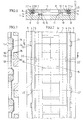
- 1, 1 generally designates a track with rails 2, whose head part 3 each on the outside of the rail via an elastomer profile 4 on a console bar 5, and each on the Inside of the rail via an elastomer profile 6 on a console bar 7 is supported.
- the elastomer profiles 4, 6 extend itself from the head part 3 to the foot part 8, the elastomer profiles 4, 6 are pressed together by the console strips 5, 7, so that the rails 2 are fixed in the lateral direction.
- the two console strips 5 are on the outside of the rail on upwardly projecting side parts 9 one below the rails 2 lying base plate 10 which is rectangular in plan arranged integrated.
- the two are similar Console strips 7 on the inside of the rail integrated on the lateral ends one between the rails 2 and above the Base plate 10 lying, rectangular inner plate in plan 11 arranged, which are on the elastomer bands 12 on the Base plate 10 supports.
- FIGS. 2 and 3 have the base plate 10 and the inner plate 11 the same Length, but are offset by half a length to each other arranged.
- each base plate 10 has two spaced apart arranged and upwardly directed longitudinal ribs 13 that are interrupted in the middle area or reduced in height are a recess for receiving longitudinal ribs 14 to form at the end portions of the inner plate 11 aligned with the longitudinal ribs 13 and directed downwards, the longitudinal ribs 13, 14 at the mutual transitions to the respective plate body of the base plate 10 or the inner plate 11 trained obliquely and so in height are dimensioned so that a space for receiving the elastomer bands 12 lying between the longitudinal ribs 13, 14 is formed.
- the longitudinal ribs engage 13, 14 when assembling the plates 10, 11 in the between the Longitudinal ribs formed complementary projections and recesses like a toothing and form a positive Longitudinal connection.
- the base plates 10 and the inner plates 11 can be used as Finished parts are manufactured, preferably reinforced concrete, Polymer concrete or special concrete, e.g. with additives, used is, and the plates 10, 11, if desired, with one reinforcement shown can be provided.
- the base plate 10 can also be manufactured in in-situ concrete.
- the plates 10, 11 to save material in the middle each provided with a rectangular recess 15 or 16, to which the longitudinal ribs 13 and 14 connect laterally. By the recesses 15 and 16 give the plates 10, 11 the shape of a frame, possibly with a closed bottom is provided.
- the base plate 10 to increase the load capacity one of the side parts 9 outgoing and reinforced reinforcement 17, as indicated in FIG. 4 with dash-dotted lines is.
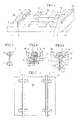
- a rail 2 ' is shown, which instead of one Foot part has a second head part 3 ', so that the rail 2 'after excessive wear, especially on the flange side, removed and reinstalled upside down can.
- Each rail 2 'can thus be used a total of four times Find.
- Fig. 6 shows an arrangement in which the height of the elastomer profile 4 'on the outside of the rail below the head part 3 greater than the height of the elastomer profile 6 'on the inside of the rail is to the deflection of the elastomer profile 6 'and to compensate for the elastomer bands 12.
- the height of the elastomer profile 6 'an inevitable Tilt the rail 2 to the inside as by the second inclined central axis shown in FIG M is indicated, so that the rails are tapered adjust turned treads of a wheel tire and none The flange is worn.
- the rails are 2 in Distances of 10 to 60 m at fixed points rigid with one Foundation 19 connected, as shown in Fig.7.
- the foot part formed as a bead 23 the two elastomer profiles 4 " and 6 "each have a width when removed that equal to half the distance between the two console strips 5 and 7.
- the two elastomer profiles 4 "and 6" can also be formed in one piece by their lower end are connected as shown with dashed lines is. In the transition area are then arranged at a distance Openings 24 are provided which allow an air outlet or air inlet allow when installing and removing the 2 "rail.
- the base plate 10 For street crossings at the same level, that is at least Inner plate 11 executed without opening 16.
- the base plate 10 has in Outline the shape of an isosceles trapezoid while the inner plate 11, each of which is two halves of the base plates 10 overlaps, correspondingly a shape of two in the floor plan composite uneven-legged trapezoids.
- the elastomer bands 12 are first on the Longitudinal ribs of the base plate 10 placed and the rails 2, 2 ' with pliers to the console strips 5 of the base plate 10 pressed, whereupon the inner plate 11, possibly in an inclined position, is used in the base plate 10. Now the elastomer profiles 6, 6 'between the console strips 7 of the inner plate 11 and the rails 2, 2 'inserted in the track direction. Subsequently the rails 2, 2 'from the outside with the pliers pressed together and the elastomer profiles 4, 4 'preferably over the recesses 22 "'between the console strips 5 of the Base plate 10 and the rails 2, 2 'inserted or moved in.
- console strips 5 and 7 or the elastomer profiles 4 and 6 the headboard, bridge and footboard of these profiles can be adjusted.
- the distance between the console strips 5 and 7 to the top of the Base plate 10 is selected so that the foot part 8, 8 'of the rail 2 always, also in the case of load, at a distance from the top the base plate 10 extends.
- the inclination mentioned above the rail 2 can also be achieved in that the distance the console strips 5 on the outside of the rail to the top the base plate 10 is greater than the distance between the console bar 7 on the inside of the rail to the top of the base plate 10 is chosen.
- the foot part by cutting with a cutting torch or laser reduced to the required width on one or both sides becomes.
- the elastomer profiles 4, 4 'and 6, 6' can either be cut to length inserted or used with each plate unit a lubricant inserted over the recesses 22 "' or to be confiscated.
- the upper one Contact surface of the console strips 5, 7 of the base plate 10 and the inner plate 11 substantially parallel to the lower support surface the head part 3 of the rails 2, 3, i.e. aslant, run.
Claims (33)
- Voie ferrée, dont les rails (2) sont supportées latéralement et vers le bas par l'intermédiaire d'inserts intercalaires élastiques (4, 6) au-dessous de la partie en forme de champignon (3), au niveau du côté extérieur et du côté intérieur des rails, sur des supports longitudinaux, et dans laquelle les rails sont disposés à une certaine distance au-dessus des composants sous-jacents de la voie et il est prévu une plaque de base qui s'étend au-dessous des rails, caractérisée en ce que les supports longitudinaux situés sur le côté extérieur des rails sont des premières barrettes en console (5), qui font partie de la plaque de base (10) qui s'étend au-dessous des rails (2 ; 2' ; 2"), et que les supports longitudinaux situés sur le côté intérieur des rails sont des deuxièmes barrettes en console (7), qui font partie d'une plaque intérieure (11) située entre les rails (2 ; 2' ; 2") et, pour leur part, sont supportés par la plaque de base (10).
- Voie ferrée selon la revendication 1, caractérisée en ce que la plaque de base (10) possède, sur le côté extérieur des rails, des parties latérales (9) qui font saillie vers le haut et sur lesquelles les premières barrettes en console (5) sont disposées de façon intégrée, et que les deuxièmes barrettes en console (7) sont disposées d'une manière intégrée sur les extrémités latérales de la plaque intérieure (11).
- Voie ferrée selon la revendication 1 ou 2, caractérisée en ce que la plaque de base (10) et la plaque intérieure (11) possèdent des longueurs identiques et sont disposées en étant décalées l'une par rapport à l'autre dans la direction longitudinale.
- Voie ferrée selon une ou plusieurs des revendications 1 à 3, caractérisée en ce que la plaque de base (10) et/ou la plaque intérieure (11) comportent au moins une nervure longitudinale (13, 14) servant au support de la plaque intérieure (11) sur la plaque de base (10).
- Voie ferrée selon la revendication 4, caractérisée en ce qu'une bande d'élastomère (12) est disposée entre la nervure longitudinale (13, 14) de la plaque de base (10) et la plaque intérieure (20) ou entre une nervure longitudinale prévue sur la plaque intérieure et la plaque de base.
- Voie ferrée selon la revendication 4 ou 5, caractérisée en ce que la plaque de base (10) comporte deux nervures longitudinales (13) qui sont situées à distance l'une de l'autre et sont dirigées vers le haut et qui sont interrompues ou dont la hauteur est réduite dans leur partie médiane, et que la plaque intérieure (11) comporte, sur ses parties d'extrémité, deux nervures longitudinales (14) alignées avec les nervures longitudinales (13) de la plaque de base (10).
- Voie ferrée selon la revendication 6, caractérisée en ce que les nervures longitudinales (13, 14) sont agencées avec une forme biseautée au niveau des jonctions alternées en direction du corps respectif de la plaque de base (10) ou de la plaque intérieure (11).
- Voie ferrée selon une ou plusieurs des revendications 1 à 7, caractérisée en ce qu'aussi bien la plaque de base (10) que la plaque intérieure (11) comportent, en leur centre, un évidement respectif (15, 16) de préférence de forme rectangulaire, pour former un cadre.
- Voie ferrée selon la revendication 8, caractérisée en ce que le cadre comporte un fond fermé.
- Voie ferrée selon une ou plusieurs des revendications 1 à 9, caractérisée en ce que la plaque de base (10) et la plaque intérieure (11) sont agencées sous la forme d'une pièce préfabriquée, réalisée de préférence en béton armé, en béton de polymère ou en béton spécial.
- Voie ferrée selon une ou plusieurs des revendications 1 à 9, caractérisée en ce que la plaque de base (10) est réalisée en béton coulé sur place.
- Voie ferrée selon la revendication 10 ou 11, caractérisée en ce que la plaque de base (10) et la plaque intérieure (11) sont équipées d'une armature.
- Voie ferrée selon la revendication 12, caractérisée en ce que des profilés longitudinaux métalliques (18) sont disposés de préférence sur l'extrémité supérieure des parties latérales (9) de la plaque de base (10), les profilés de plaques de base successives (10) étant reliés entre eux électriquement et/ou étant raccordés à la terre.
- Voie ferrée selon l'une des revendications 1 à 13, caractérisée en ce que les barrettes en console (5, 7 ; 5', 7') et les inserts intercalaires élastiques agencés sous la forme de profilés en élastomère (4, 6 ; 4', 6') sont adaptés à la forme de la partie en forme de champignon, de l'âme et de la partie de base du rail (2 ; 2').
- Voie ferrée selon l'une des revendications précédentes, caractérisée en ce que les rails (2'), qui sont supportés par les barrettes en console (5, 7 ; 5', 7') d'une plaque de base (10) et des plaques inférieures (11), possèdent une partie formant semelle (3'), qui est agencée de la même manière que la partie en forme de champignon (3).
- Voie ferrée selon la revendication 15, caractérisée en ce que la largeur de la partie formant semelle (8 ; 23) des rails (2 ; 2") est égale ou inférieure à la distance entre les première et seconde barrettes en console (5, 7).
- Voie ferrée selon l'une des revendications 1 à 16, caractérisée en ce que la plaque de base (10) et la plaque intérieure (11) sont agencées avec un contour rectangulaire en projection horizontale et possèdent la même longueur, la plaque de base (10) et la plaque intérieure (11) étant disposées en étant réciproquement décalées dans la direction longitudinale.
- Voie ferrée selon la revendication 10, caractérisée en ce que la plaque de base (10') a un contour en projection horizontale possédant la forme d'un trapèze à côtés obliques égaux, et que la plaque intérieure (11') a un contour en projection horizontale possédant la forme de deux trapèzes réunis possédant des côtés obliques inégaux et qui sont agencés tous deux de manière à correspondre chacun à la forme de la moitié d'une plaque de base (10).
- Voie ferrée selon la revendication 1 ou 2, caractérisée en ce que la hauteur du profilé élastomère (4') sur le côté extérieur des rails, au-dessous de la partie en forme de champignon (3), est supérieure à la hauteur du profilé en élastomère (6') sur le côté intérieur des rails.
- Voie ferrée selon la revendication 1 ou 2, caractérisée en ce que la distance entre la barrette en console (5') située sur le côté extérieur des rails et le bord supérieur de la plaque de base est supérieure à la distance entre la barrette en console (7') située sur le côté intérieur des rails et le bord supérieur de la plaque intérieure (11).
- Voie ferrée selon la revendication 1, caractérisée en ce que les plaques de base (10), qui sont agencées sous la forme de pièces préfabriquées, sont reliées rigidement à une fondation (19), à des intervalles de 10 à 60 m.
- Voie ferrée selon la revendication 21, caractérisée en ce que sur les plaques de base (10), reliées à une fondation (19) ou directement sur la fondation (19) sont ancrées des plaques métalliques (20), sur lesquelles sont montés des éléments (21) de fixation des rails.
- Voie ferrée selon la revendication 2, caractérisée en ce que des évidements centraux (22, 22') sont prévus sur le côté intérieur sur les parties latérales (9) de la plaque de base (10) et éventuellement sur le côté extérieur sur les parties latérales de la plaque intérieure (11), les parties en console (5) et les profilés en élastomère associés (6 ; 6') étant interrompus dans la zone des évidements (22).
- Voie ferrée selon la revendication 2, caractérisée en ce que la plaque de base (10) possède un élargissement (17) qui s'étend à partir des parties latérales (9).
- Voie ferrée selon la revendication 18, caractérisée en ce que la partie formant semelle (8) des rails.(2") est agencée sous la forme d'un bourrelet (23), les profilés en élastomère (4", 6") possédant chacun, à l'état démonté, une largeur égale à la moitié de la distance entre les deux barrettes en console (5, 7).
- Voie ferrée selon la revendication 2, caractérisée en ce qu'un évidement (22") est prévu sur les parties latérales (9) de la plaque de base (10) au niveau des zones d'aboutement.
- Voie ferrée selon la revendication 2, caractérisée en ce qu'une ouverture oblique (22"'), qui s'étend continûment de l'extérieur vers l'intérieur, est prévue dans les parties latérales (9) de la plaque de base (10) au niveau des zones d'aboutement.
- Voie ferrée selon la revendication 2, caractérisée en ce que des parois (25) formées d'un matériau insonorisant sont disposées extérieurement, d'un côté ou des deux côtés, sur les parois latérales (9) de la plaque de base (10).
- Voie ferrée selon la revendication 2, caractérisée en ce que la surface d'appui supérieure des barrettes en console (5, 7) de la plaque de base (10) et de la plaque intérieure (10) s'étend essentiellement parallèlement à la surface d'appui inférieure de la partie en forme de champignon (3) des rails (2 ; 2' ; 2").
- Procédé pour le montage d'une voie ferrée selon l'une des revendications 1 à 29, caractérisé par les étapes consistant à :a) appliquer des bandes d'élastomère (12) sur des nervures longitudinales (13) de la plaque de base (10) et placer les rails (2, 2') sur les barrettes en console (5) de la plaque de base (10),b) insérer obliquement la plaque intérieure (11) sur un côté de la plaque de base (10) et faire basculer la plaque intérieure (11) sur l'autre côté dans la plaque de base (10),c) insérer des profilés en élastomère (6, 6') entre les barrettes en console (7) de la plaque intérieure (11) et les rails (2, 2'),d) serrer les rails (2, 2') à partir de l'extérieur et insérer des profilés en élastomère (4, 4') entre les barrettes en console (5) de la plaque de base (10) et les rails (2, 2'),e) détendre les rails (2, 2') vers l'extérieur de sorte que les rails (2, 2') sont serrés entre les profilés en élastomère situés sur les barrettes en console (5, 7).
- Procédé pour le montage d'une voie ferrée selon l'une des revendications 1 à 29, caractérisé par les étapes consistant à :a) monter des profilés en élastomère (6, 6') sur les barrettes en console (7, 7') de la plaque intérieure (11) et placer les rails (2, 2') sur les profilés en élastomère (6, 6'),b) serrer les rails (2, 2') à partir de l'extérieur,c) introduire des bandes d'élastomère (12) sur des nervures longitudinales (13) de la plaque de base (10) et insérer les rails (2, 2') conjointement avec la plaque intérieure (1) dans la plaque de base (10),d) insérer des profilés en élastomère (4, 4') entre les barrettes en console (5) de la plaque de base (10) et les rails (2, 2'), ete) détendre les rails (2, 2') vers l'extérieur de sorte que les rails (2, 2') sont serrés entre les profilés en élastomère situés sur les barrettes en console (5, 7).
- Procédé pour le montage d'une voie ferrée selon l'une des revendications 1 à 29, caractérisé par les étapes consistant à :a) appliquer des bandes d'élastomère (12) sur des nervures longitudinales (13) de la plaque de base (10) et introduire la plaque intérieure (11) dans la plaque de base (10),b) placer des profilés en élastomère (4, 4', 6, 6') sur les deux côtés des rails (2, 2'), etc) enfoncer les rails (2, 2') ainsi que les profilés en élastomère (4, 4',6, 6') entre les barrettes en console (5, 5') de la plaque de base (10) et les barrettes en console (7, 7') de la plaque intérieure (11), éventuellement moyennant l'interposition d'une bande de tôle entre les barrettes en console (5, 5', 7, 7').
- Procédé pour le montage d'une voie selon l'une des revendications 1 à 28, caractérisé par les étapes consistant à :a) appliquer des bandes en élastomère (12) sur des nervures longitudinales (13) de la plaque de base (10) et introduire la plaque intérieure (11) dans la plaque de base (10),b) introduire des profilés en élastomère (4", 6") entre les barrettes en console (5, 5') de la plaque de base (10) et les barrettes en console (7, 7') de la plaque intérieure (11), etc) enfoncer les rails (2'').
Applications Claiming Priority (4)
| Application Number | Priority Date | Filing Date | Title |
|---|---|---|---|
| AT0243394A AT403386B (de) | 1994-12-30 | 1994-12-30 | Gleis |
| AT24339/49 | 1994-12-30 | ||
| AT2433/94 | 1994-12-30 | ||
| PCT/AT1995/000252 WO1996021063A1 (fr) | 1994-12-30 | 1995-12-22 | Voie ferree |
Publications (2)
| Publication Number | Publication Date |
|---|---|
| EP0800599A1 EP0800599A1 (fr) | 1997-10-15 |
| EP0800599B1 true EP0800599B1 (fr) | 1998-05-20 |
Family
ID=3534267
Family Applications (1)
| Application Number | Title | Priority Date | Filing Date |
|---|---|---|---|
| EP95940079A Expired - Lifetime EP0800599B1 (fr) | 1994-12-30 | 1995-12-22 | Voie ferree |
Country Status (16)
| Country | Link |
|---|---|
| US (1) | US5806764A (fr) |
| EP (1) | EP0800599B1 (fr) |
| JP (1) | JP3602137B2 (fr) |
| KR (1) | KR100405939B1 (fr) |
| CN (1) | CN1096530C (fr) |
| AT (2) | AT403386B (fr) |
| AU (1) | AU699601B2 (fr) |
| CZ (1) | CZ145497A3 (fr) |
| DE (1) | DE59502289D1 (fr) |
| ES (1) | ES2118643T3 (fr) |
| FI (1) | FI119776B (fr) |
| HU (1) | HU218774B (fr) |
| NO (1) | NO309106B1 (fr) |
| PL (1) | PL178301B1 (fr) |
| SK (1) | SK78597A3 (fr) |
| WO (1) | WO1996021063A1 (fr) |
Families Citing this family (7)
| Publication number | Priority date | Publication date | Assignee | Title |
|---|---|---|---|---|
| DE19920146B4 (de) * | 1999-05-03 | 2005-07-21 | Max Bögl Bauunternehmung GmbH & Co. KG | Lagerung einer Schiene für Schienenfahrzeuge |
| DE19920075A1 (de) * | 1999-05-03 | 2000-12-07 | Boegl Max Bauunternehmung Gmbh | Lagerung einer Schiene für Schienenfahrzeuge |
| NL1012649C2 (nl) * | 1999-07-20 | 2001-01-23 | Grimbergen Holding B V | Spoorplaat voor een spoorbaan, en bevestigingsmethode daarvoor. |
| KR100711202B1 (ko) | 2005-12-10 | 2007-04-24 | 송억영 | 중앙안내방식 단일레일궤도 트램카 |
| AU2007260579B2 (en) * | 2006-06-13 | 2012-09-06 | Newstyle Nominees Pty Ltd | Rail track crossing |
| DE102006043745A1 (de) * | 2006-09-13 | 2008-04-03 | Max Bögl Bauunternehmung GmbH & Co. KG | Fahrweg und Verfahren zur Herstellung eines Fahrweges |
| FR2938274B1 (fr) * | 2008-11-10 | 2016-02-05 | Alstom Transport Sa | Superstructure de voie fixe sans ballast avec sectionnement de la dalle de fondation |
Family Cites Families (15)
| Publication number | Priority date | Publication date | Assignee | Title |
|---|---|---|---|---|
| US1260149A (en) * | 1917-10-13 | 1918-03-19 | William G Coughlin | Railroad-rail and support. |
| US1587691A (en) * | 1924-10-23 | 1926-06-08 | Richard A Whittingham | Railway-track structure |
| AT227289B (de) * | 1961-01-20 | 1963-05-10 | Meteoor Nv Betonfabriek | Gleislagerung auf Blockschwellen |
| US3525472A (en) * | 1966-08-30 | 1970-08-25 | Japan National Railway | Vibration-suppressing composite rail for railways |
| JPS5251605A (en) * | 1975-10-24 | 1977-04-25 | Yutaka Sato | Rail viebration insulating and tighteing device |
| DE2817278C3 (de) * | 1978-04-20 | 1980-10-30 | Diether 4300 Essen Uderstaedt | Schalldämmende Schienenunterlage |
| GB2024289B (en) * | 1978-06-30 | 1983-03-30 | Clouth Gummiwerke Ag | Resilient rail support |
| AT367482B (de) * | 1980-05-20 | 1982-07-12 | Hoetzel Beton Gmbh | Schienengleicher bahnuebergang mit innenplatten aus beton |
| US4616395A (en) * | 1983-06-30 | 1986-10-14 | Perini Corporation | Railroad track fixation method and apparatus |
| DE3536966A1 (de) * | 1985-10-17 | 1987-04-23 | Uderstaedt Diether | Schienenunterbau |
| DE3540128A1 (de) * | 1985-11-13 | 1987-05-14 | Clouth Gummiwerke Ag | Elastisch gelagerte schiene fuer schienenfahrzeuge |
| BE903871A (fr) * | 1985-12-17 | 1986-04-16 | Dynamit Du Batiment En Abrege | Systeme de voie ferree antivibratoire. |
| DE4007937C2 (de) * | 1990-03-13 | 2002-03-21 | Hermann Ortwein | Elastisch gelagerte Schiene für Schienenfahrzeuge |
| DE4114803A1 (de) * | 1991-05-07 | 1992-11-12 | Hermann Ortwein | Rillenschiene |
| DE4311452C2 (de) * | 1993-04-07 | 2000-03-09 | Wuerzburger Strassenbahn Gmbh | Elastische Schienenlagerung mit offenem oder geschlossenem Oberbau für Schienenfahrzeuge |
-
1994
- 1994-12-30 AT AT0243394A patent/AT403386B/de not_active IP Right Cessation
-
1995
- 1995-12-22 PL PL95320997A patent/PL178301B1/pl not_active IP Right Cessation
- 1995-12-22 SK SK785-97A patent/SK78597A3/sk unknown
- 1995-12-22 HU HU9701738A patent/HU218774B/hu not_active IP Right Cessation
- 1995-12-22 ES ES95940079T patent/ES2118643T3/es not_active Expired - Lifetime
- 1995-12-22 EP EP95940079A patent/EP0800599B1/fr not_active Expired - Lifetime
- 1995-12-22 AT AT95940079T patent/ATE166405T1/de active
- 1995-12-22 WO PCT/AT1995/000252 patent/WO1996021063A1/fr active IP Right Grant
- 1995-12-22 DE DE59502289T patent/DE59502289D1/de not_active Expired - Lifetime
- 1995-12-22 CZ CZ971454A patent/CZ145497A3/cs unknown
- 1995-12-22 US US08/702,588 patent/US5806764A/en not_active Expired - Lifetime
- 1995-12-22 JP JP52063296A patent/JP3602137B2/ja not_active Expired - Fee Related
- 1995-12-22 AU AU41678/96A patent/AU699601B2/en not_active Ceased
- 1995-12-22 CN CN95197065A patent/CN1096530C/zh not_active Expired - Fee Related
- 1995-12-22 KR KR1019970704353A patent/KR100405939B1/ko not_active IP Right Cessation
-
1997
- 1997-06-27 FI FI972782A patent/FI119776B/fi not_active IP Right Cessation
- 1997-06-30 NO NO973053A patent/NO309106B1/no not_active IP Right Cessation
Also Published As
| Publication number | Publication date |
|---|---|
| PL178301B1 (pl) | 2000-04-28 |
| US5806764A (en) | 1998-09-15 |
| ATA243394A (de) | 1997-06-15 |
| JP3602137B2 (ja) | 2004-12-15 |
| SK78597A3 (en) | 1998-01-14 |
| JPH10511754A (ja) | 1998-11-10 |
| KR100405939B1 (ko) | 2004-04-29 |
| NO973053D0 (no) | 1997-06-30 |
| AU699601B2 (en) | 1998-12-10 |
| DE59502289D1 (de) | 1998-06-25 |
| AT403386B (de) | 1998-01-26 |
| HUT76961A (hu) | 1998-01-28 |
| AU4167896A (en) | 1996-07-24 |
| ES2118643T3 (es) | 1998-09-16 |
| HU218774B (hu) | 2000-12-28 |
| CN1171139A (zh) | 1998-01-21 |
| PL320997A1 (en) | 1997-11-24 |
| EP0800599A1 (fr) | 1997-10-15 |
| NO309106B1 (no) | 2000-12-11 |
| WO1996021063A1 (fr) | 1996-07-11 |
| NO973053L (no) | 1997-06-30 |
| CZ145497A3 (en) | 1997-08-13 |
| FI972782A0 (fi) | 1997-06-27 |
| ATE166405T1 (de) | 1998-06-15 |
| CN1096530C (zh) | 2002-12-18 |
| FI119776B (fi) | 2009-03-13 |
| FI972782A (fi) | 1997-06-27 |
Similar Documents
| Publication | Publication Date | Title |
|---|---|---|
| EP0420882A1 (fr) | Rail pour vehicules sur rails. | |
| EP0800599B1 (fr) | Voie ferree | |
| DE19920858C2 (de) | Oberbau-Zungenvorrichtung | |
| DE2123225A1 (de) | Zusammengesetzte Ausdehnungsverbindung | |
| EP1165968A1 (fr) | Support reglable en hauteur situe entre deux plaques paralleles | |
| EP1637653B1 (fr) | Structure de support latérale pour dispositif de passage à niveau de voies ferrées | |
| DE202009018663U1 (de) | Vorrichtung zur Überbrückung von Dehnfugen und Profilkonstruktion | |
| EP1203123B1 (fr) | Voie pour vehicule guide, en particulier pour train a sustentation magnetique | |
| DE4132960C2 (de) | Fahrweg für Magnetbahnfahrzeuge in Stahlbauweise sowie Verfahren und Vorrichtu ng zu seiner Herstellung | |
| DE60009330T2 (de) | Vorrichtung und verfahren zur befestigung eines flachelements an einem fahrzeug | |
| EP1114221B1 (fr) | Structure de traverses destinee a une voie ferree destinee a des vehicules ferroviaires, notamment a une voie ballastee | |
| EP0853706B1 (fr) | Passage a niveau | |
| EP1718802B1 (fr) | Traverse en double croix pour superstructure ballastee | |
| DE4425037C1 (de) | Fahrbahnübergang | |
| EP1573133B1 (fr) | Traverse de chassis et son procede de production | |
| DE19920146B4 (de) | Lagerung einer Schiene für Schienenfahrzeuge | |
| EP1800986B1 (fr) | Système d'assemblage pour une structure de paroi ou de sol | |
| EP1232084B1 (fr) | Support transversal principal pour vehicules sur rails, constitue d'un profile de grande taille en aluminium | |
| EP0456639B1 (fr) | Dispositif pour le recouvrement et l'etanchement de joints de dilatation, en particulier dans des chaussees | |
| DE1534108A1 (de) | Gleiskonstruktion | |
| WO2005080173A1 (fr) | Dispositif colonne de direction pour un véhicule | |
| DE212018000058U1 (de) | Dehnungsfugenstruktur einer Brücke | |
| DE3017048A1 (de) | Fugenueberbrueckungsvorrichtung fuer dehnfugen in bruecken o.dgl. | |
| EP2072681B1 (fr) | Console pour rails installés temporairement | |
| DE202011005031U1 (de) | Schienenauszugsvorrichtung |
Legal Events
| Date | Code | Title | Description |
|---|---|---|---|
| PUAI | Public reference made under article 153(3) epc to a published international application that has entered the european phase |
Free format text: ORIGINAL CODE: 0009012 |
|
| 17P | Request for examination filed |
Effective date: 19970705 |
|
| AK | Designated contracting states |
Kind code of ref document: A1 Designated state(s): AT BE CH DE DK ES FR GB GR IE IT LI LU NL PT SE |
|
| AX | Request for extension of the european patent |
Free format text: SI PAYMENT 970705 |
|
| GRAG | Despatch of communication of intention to grant |
Free format text: ORIGINAL CODE: EPIDOS AGRA |
|
| GRAG | Despatch of communication of intention to grant |
Free format text: ORIGINAL CODE: EPIDOS AGRA |
|
| GRAH | Despatch of communication of intention to grant a patent |
Free format text: ORIGINAL CODE: EPIDOS IGRA |
|
| 17Q | First examination report despatched |
Effective date: 19971017 |
|
| GRAH | Despatch of communication of intention to grant a patent |
Free format text: ORIGINAL CODE: EPIDOS IGRA |
|
| GRAA | (expected) grant |
Free format text: ORIGINAL CODE: 0009210 |
|
| AK | Designated contracting states |
Kind code of ref document: B1 Designated state(s): AT BE CH DE DK ES FR GB GR IE IT LI LU NL PT SE |
|
| AX | Request for extension of the european patent |
Free format text: SI PAYMENT 970705 |
|
| PG25 | Lapsed in a contracting state [announced via postgrant information from national office to epo] |
Ref country code: NL Free format text: LAPSE BECAUSE OF FAILURE TO SUBMIT A TRANSLATION OF THE DESCRIPTION OR TO PAY THE FEE WITHIN THE PRESCRIBED TIME-LIMIT Effective date: 19980520 Ref country code: GR Free format text: LAPSE BECAUSE OF NON-PAYMENT OF DUE FEES Effective date: 19980520 |
|
| REF | Corresponds to: |
Ref document number: 166405 Country of ref document: AT Date of ref document: 19980615 Kind code of ref document: T |
|
| REG | Reference to a national code |
Ref country code: CH Ref legal event code: EP |
|
| REF | Corresponds to: |
Ref document number: 59502289 Country of ref document: DE Date of ref document: 19980625 |
|
| ITF | It: translation for a ep patent filed |
Owner name: BARZANO' E ZANARDO MILANO S.P.A. |
|
| REG | Reference to a national code |
Ref country code: CH Ref legal event code: NV Representative=s name: A. BRAUN, BRAUN, HERITIER, ESCHMANN AG PATENTANWAE |
|
| GBT | Gb: translation of ep patent filed (gb section 77(6)(a)/1977) |
Effective date: 19980724 |
|
| PG25 | Lapsed in a contracting state [announced via postgrant information from national office to epo] |
Ref country code: DK Free format text: LAPSE BECAUSE OF FAILURE TO SUBMIT A TRANSLATION OF THE DESCRIPTION OR TO PAY THE FEE WITHIN THE PRESCRIBED TIME-LIMIT Effective date: 19980820 |
|
| REG | Reference to a national code |
Ref country code: IE Ref legal event code: FG4D Free format text: GERMAN |
|
| REG | Reference to a national code |
Ref country code: ES Ref legal event code: FG2A Ref document number: 2118643 Country of ref document: ES Kind code of ref document: T3 |
|
| ET | Fr: translation filed | ||
| NLV1 | Nl: lapsed or annulled due to failure to fulfill the requirements of art. 29p and 29m of the patents act | ||
| REG | Reference to a national code |
Ref country code: PT Ref legal event code: SC4A Free format text: AVAILABILITY OF NATIONAL TRANSLATION Effective date: 19980817 |
|
| PG25 | Lapsed in a contracting state [announced via postgrant information from national office to epo] |
Ref country code: IE Free format text: LAPSE BECAUSE OF NON-PAYMENT OF DUE FEES Effective date: 19981211 |
|
| PG25 | Lapsed in a contracting state [announced via postgrant information from national office to epo] |
Ref country code: LU Free format text: LAPSE BECAUSE OF NON-PAYMENT OF DUE FEES Effective date: 19981222 |
|
| REG | Reference to a national code |
Ref country code: IE Ref legal event code: FD4D |
|
| PG25 | Lapsed in a contracting state [announced via postgrant information from national office to epo] |
Ref country code: BE Free format text: LAPSE BECAUSE OF NON-PAYMENT OF DUE FEES Effective date: 19981231 |
|
| PLBE | No opposition filed within time limit |
Free format text: ORIGINAL CODE: 0009261 |
|
| STAA | Information on the status of an ep patent application or granted ep patent |
Free format text: STATUS: NO OPPOSITION FILED WITHIN TIME LIMIT |
|
| 26N | No opposition filed | ||
| BERE | Be: lapsed |
Owner name: GMUNDNER FERTIGTEILE G.M.B.H. & CO. K.G. Effective date: 19981231 |
|
| REG | Reference to a national code |
Ref country code: GB Ref legal event code: IF02 |
|
| REG | Reference to a national code |
Ref country code: CH Ref legal event code: PFA Owner name: GMUNDNER FERTIGTEILE GESELLSCHAFT M.B.H. & CO. KG Free format text: GMUNDNER FERTIGTEILE GESELLSCHAFT M.B.H. & CO. KG.#KUFERZEILE 30-32#A-4810 GMUNDEN (AT) -TRANSFER TO- GMUNDNER FERTIGTEILE GESELLSCHAFT M.B.H. & CO. KG.#KUFERZEILE 30-32#A-4810 GMUNDEN (AT) |
|
| PGFP | Annual fee paid to national office [announced via postgrant information from national office to epo] |
Ref country code: SE Payment date: 20111219 Year of fee payment: 17 Ref country code: PT Payment date: 20110930 Year of fee payment: 17 Ref country code: FR Payment date: 20111018 Year of fee payment: 17 Ref country code: ES Payment date: 20111115 Year of fee payment: 17 |
|
| PGFP | Annual fee paid to national office [announced via postgrant information from national office to epo] |
Ref country code: CH Payment date: 20121224 Year of fee payment: 18 |
|
| PGFP | Annual fee paid to national office [announced via postgrant information from national office to epo] |
Ref country code: GB Payment date: 20121123 Year of fee payment: 18 Ref country code: IT Payment date: 20121207 Year of fee payment: 18 |
|
| PGFP | Annual fee paid to national office [announced via postgrant information from national office to epo] |
Ref country code: AT Payment date: 20121220 Year of fee payment: 18 |
|
| PGFP | Annual fee paid to national office [announced via postgrant information from national office to epo] |
Ref country code: DE Payment date: 20130227 Year of fee payment: 18 |
|
| REG | Reference to a national code |
Ref country code: PT Ref legal event code: MM4A Free format text: LAPSE DUE TO NON-PAYMENT OF FEES Effective date: 20130624 |
|
| PG25 | Lapsed in a contracting state [announced via postgrant information from national office to epo] |
Ref country code: SE Free format text: LAPSE BECAUSE OF NON-PAYMENT OF DUE FEES Effective date: 20121223 |
|
| PG25 | Lapsed in a contracting state [announced via postgrant information from national office to epo] |
Ref country code: PT Free format text: LAPSE BECAUSE OF NON-PAYMENT OF DUE FEES Effective date: 20130624 |
|
| REG | Reference to a national code |
Ref country code: FR Ref legal event code: ST Effective date: 20130830 |
|
| PG25 | Lapsed in a contracting state [announced via postgrant information from national office to epo] |
Ref country code: FR Free format text: LAPSE BECAUSE OF NON-PAYMENT OF DUE FEES Effective date: 20130102 |
|
| REG | Reference to a national code |
Ref country code: ES Ref legal event code: FD2A Effective date: 20140307 |
|
| PG25 | Lapsed in a contracting state [announced via postgrant information from national office to epo] |
Ref country code: ES Free format text: LAPSE BECAUSE OF NON-PAYMENT OF DUE FEES Effective date: 20121223 |
|
| REG | Reference to a national code |
Ref country code: DE Ref legal event code: R119 Ref document number: 59502289 Country of ref document: DE |
|
| REG | Reference to a national code |
Ref country code: CH Ref legal event code: PL |
|
| REG | Reference to a national code |
Ref country code: AT Ref legal event code: MM01 Ref document number: 166405 Country of ref document: AT Kind code of ref document: T Effective date: 20131222 |
|
| GBPC | Gb: european patent ceased through non-payment of renewal fee |
Effective date: 20131222 |
|
| REG | Reference to a national code |
Ref country code: DE Ref legal event code: R119 Ref document number: 59502289 Country of ref document: DE Effective date: 20140701 |
|
| PG25 | Lapsed in a contracting state [announced via postgrant information from national office to epo] |
Ref country code: DE Free format text: LAPSE BECAUSE OF NON-PAYMENT OF DUE FEES Effective date: 20140701 Ref country code: CH Free format text: LAPSE BECAUSE OF NON-PAYMENT OF DUE FEES Effective date: 20131231 Ref country code: LI Free format text: LAPSE BECAUSE OF NON-PAYMENT OF DUE FEES Effective date: 20131231 |
|
| PG25 | Lapsed in a contracting state [announced via postgrant information from national office to epo] |
Ref country code: GB Free format text: LAPSE BECAUSE OF NON-PAYMENT OF DUE FEES Effective date: 20131222 Ref country code: AT Free format text: LAPSE BECAUSE OF NON-PAYMENT OF DUE FEES Effective date: 20131222 |
|
| PG25 | Lapsed in a contracting state [announced via postgrant information from national office to epo] |
Ref country code: IT Free format text: LAPSE BECAUSE OF NON-PAYMENT OF DUE FEES Effective date: 20131222 |