EP0800599B1 - Railway track - Google Patents
Railway track Download PDFInfo
- Publication number
- EP0800599B1 EP0800599B1 EP95940079A EP95940079A EP0800599B1 EP 0800599 B1 EP0800599 B1 EP 0800599B1 EP 95940079 A EP95940079 A EP 95940079A EP 95940079 A EP95940079 A EP 95940079A EP 0800599 B1 EP0800599 B1 EP 0800599B1
- Authority
- EP
- European Patent Office
- Prior art keywords
- base plate
- rails
- track according
- plate
- inner plate
- Prior art date
- Legal status (The legal status is an assumption and is not a legal conclusion. Google has not performed a legal analysis and makes no representation as to the accuracy of the status listed.)
- Expired - Lifetime
Links
- 239000000969 carrier Substances 0.000 claims abstract 6
- 229920001971 elastomer Polymers 0.000 claims description 70
- 239000000806 elastomer Substances 0.000 claims description 70
- 239000002184 metal Substances 0.000 claims description 10
- 239000004567 concrete Substances 0.000 claims description 9
- 238000000034 method Methods 0.000 claims description 9
- 238000003825 pressing Methods 0.000 claims description 6
- 239000011324 bead Substances 0.000 claims description 5
- 230000007704 transition Effects 0.000 claims description 5
- 230000002787 reinforcement Effects 0.000 claims description 4
- 239000011358 absorbing material Substances 0.000 claims description 3
- 229920000642 polymer Polymers 0.000 claims description 2
- 238000003780 insertion Methods 0.000 description 5
- 230000037431 insertion Effects 0.000 description 5
- 238000009434 installation Methods 0.000 description 5
- 239000000463 material Substances 0.000 description 3
- 238000005520 cutting process Methods 0.000 description 2
- 238000006073 displacement reaction Methods 0.000 description 2
- 230000000694 effects Effects 0.000 description 2
- 230000002349 favourable effect Effects 0.000 description 2
- 238000011065 in-situ storage Methods 0.000 description 2
- FGRBYDKOBBBPOI-UHFFFAOYSA-N 10,10-dioxo-2-[4-(N-phenylanilino)phenyl]thioxanthen-9-one Chemical compound O=C1c2ccccc2S(=O)(=O)c2ccc(cc12)-c1ccc(cc1)N(c1ccccc1)c1ccccc1 FGRBYDKOBBBPOI-UHFFFAOYSA-N 0.000 description 1
- 229910000831 Steel Inorganic materials 0.000 description 1
- 239000000654 additive Substances 0.000 description 1
- 230000005540 biological transmission Effects 0.000 description 1
- 230000000295 complement effect Effects 0.000 description 1
- 239000002131 composite material Substances 0.000 description 1
- 238000009826 distribution Methods 0.000 description 1
- 239000012530 fluid Substances 0.000 description 1
- 239000000314 lubricant Substances 0.000 description 1
- 238000004519 manufacturing process Methods 0.000 description 1
- 238000013508 migration Methods 0.000 description 1
- 230000005012 migration Effects 0.000 description 1
- 230000035515 penetration Effects 0.000 description 1
- 239000002986 polymer concrete Substances 0.000 description 1
- 239000011178 precast concrete Substances 0.000 description 1
- 239000011150 reinforced concrete Substances 0.000 description 1
- 230000035939 shock Effects 0.000 description 1
- 230000003068 static effect Effects 0.000 description 1
- 239000010959 steel Substances 0.000 description 1
- 238000003860 storage Methods 0.000 description 1
Images
Classifications
-
- E—FIXED CONSTRUCTIONS
- E01—CONSTRUCTION OF ROADS, RAILWAYS, OR BRIDGES
- E01B—PERMANENT WAY; PERMANENT-WAY TOOLS; MACHINES FOR MAKING RAILWAYS OF ALL KINDS
- E01B3/00—Transverse or longitudinal sleepers; Other means resting directly on the ballastway for supporting rails
- E01B3/28—Transverse or longitudinal sleepers; Other means resting directly on the ballastway for supporting rails made from concrete or from natural or artificial stone
- E01B3/38—Longitudinal sleepers; Longitudinal sleepers integral or combined with tie-rods; Combined longitudinal and transverse sleepers; Layers of concrete supporting both rails
-
- E—FIXED CONSTRUCTIONS
- E01—CONSTRUCTION OF ROADS, RAILWAYS, OR BRIDGES
- E01B—PERMANENT WAY; PERMANENT-WAY TOOLS; MACHINES FOR MAKING RAILWAYS OF ALL KINDS
- E01B9/00—Fastening rails on sleepers, or the like
- E01B9/60—Rail fastenings making use of clamps or braces supporting the side of the rail
-
- E—FIXED CONSTRUCTIONS
- E01—CONSTRUCTION OF ROADS, RAILWAYS, OR BRIDGES
- E01B—PERMANENT WAY; PERMANENT-WAY TOOLS; MACHINES FOR MAKING RAILWAYS OF ALL KINDS
- E01B2204/00—Characteristics of the track and its foundations
- E01B2204/11—Embedded tracks, using prefab elements or injecting or pouring a curable material
-
- E—FIXED CONSTRUCTIONS
- E01—CONSTRUCTION OF ROADS, RAILWAYS, OR BRIDGES
- E01B—PERMANENT WAY; PERMANENT-WAY TOOLS; MACHINES FOR MAKING RAILWAYS OF ALL KINDS
- E01B2204/00—Characteristics of the track and its foundations
- E01B2204/12—Floating rails or sleepers
Definitions
- the invention relates to a track, the rails of which laterally and down over elastic intermediate pads under the Headboard on the inside and outside of the rail Side rails are supported, with the rails at a distance run over the underlying track components, and a extending base plate is provided under the rails.
- the side members on the Rail outside of the first console strips that are part of the are under the rails extending base plate, and that the Side rails on the inside of the rail, second console strips are part of an inner plate lying between the rails are, which in turn is supported on the base plate.
- the Inner plate can be designed as a frame.
- An advantageous embodiment of the invention exists in that the base plate on the outside of the rail upwards has protruding side parts on which the first console strips are integrated, and that the second Console strips on the side ends of the inner plate or - frames are integrated.
- the base plate and the inner plate have the same length and half Length are offset from each other.
- the base plate and / or the inner plate at least a longitudinal rib to support the inner plate on the base plate has or have, preferably between the Longitudinal rib of the base plate and the inner plate or between a longitudinal rib provided on the inner plate and the base plate an elastomeric band is arranged so that a sound absorbing Effect and an elastic bedding is achieved.
- Another advantageous embodiment is characterized in that that the base plate two at a distance from each other arranged and directed upward longitudinal ribs, the interrupted in the middle or reduced in height are, and that the inner plate at its end regions two with the Longitudinal ribs of the base plate have aligned longitudinal ribs. This ensures that there is no mutual displacement the base and inner panels can take place in the longitudinal direction.
- the plates are expedient for weight and Material saving designed so that both the base plate and also the inner plate in the middle with one, preferably rectangular, recess are provided around a Form the frame, where appropriate the frame with a closed bottom is provided to increase the strength.
- the base plate and the inner plate as a finished part, preferably made of steel, Polymer or special concrete, trained, whereby the Reduced costs.
- the Base plate is made of in-situ concrete.
- Both the base plate and the inner plate are for It is advisable to increase its strength with reinforcement provided, which can be limp or biased.
- the base plates are preferably at the upper end of the side parts of the base plate longitudinal metal profiles arranged, the profiles successively lying base plates electrically with each other connected and / or grounded. This will also add the strength of the base plate increases.
- console strips There can be different forms in the subject matter of the invention of rail profiles are used, and they are preferred the console strips and those designed as elastomer profiles elastic intermediate pads to the shape of the headboard, the Web and the foot part of the rail adapted.
- the base plate and the inner plate are in the Floor plan is rectangular and have the same length on, with the base plate and the inner plate in the longitudinal direction are staggered.
- the base plate in Layout has the shape of an isosceles trapezoid, while the inner plate in plan is the shape of two put together has uneven-legged trapezoids, both of which corresponding to the shape of half of a base plate are trained.
- the rails are slanted to the inside adapt to the tread.
- a preferred embodiment for the inclination of the rails is characterized in that the height of the elastomer profile on the outside of the rail below of the headboard is greater than the height of the elastomer profile the inside of the rail.
- Another embodiment for Inclination of the rails is that the distance of the Console bar on the outside of the rail to the upper edge of the Base plate larger than the distance of the console bar on the Inside of the rail to the upper edge of the inner plate.
- the console strips and the associated elastomer profiles in the area of the recesses are interrupted so that the penetration of a tool, for example, the jaw of one attacking the rails Pliers, is made possible.
- the foot part of the rails as a bead is formed and the elastomer profiles in the disassembled state each have a width that is approximately equal to half the distance between the two console strips.
- the rails between the relatively easy with the Insert or insert covered console strips over the elastomer profiles and it is the rails after installing them between the elastomer profiles by the bead against one after Movement secured above. It is also for installation cheap if you have the two assigned to a rail Forms one-piece elastomer profiles by attaching them to their lower End connected.
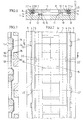
- 1, 1 generally designates a track with rails 2, whose head part 3 each on the outside of the rail via an elastomer profile 4 on a console bar 5, and each on the Inside of the rail via an elastomer profile 6 on a console bar 7 is supported.
- the elastomer profiles 4, 6 extend itself from the head part 3 to the foot part 8, the elastomer profiles 4, 6 are pressed together by the console strips 5, 7, so that the rails 2 are fixed in the lateral direction.
- the two console strips 5 are on the outside of the rail on upwardly projecting side parts 9 one below the rails 2 lying base plate 10 which is rectangular in plan arranged integrated.
- the two are similar Console strips 7 on the inside of the rail integrated on the lateral ends one between the rails 2 and above the Base plate 10 lying, rectangular inner plate in plan 11 arranged, which are on the elastomer bands 12 on the Base plate 10 supports.
- FIGS. 2 and 3 have the base plate 10 and the inner plate 11 the same Length, but are offset by half a length to each other arranged.
- each base plate 10 has two spaced apart arranged and upwardly directed longitudinal ribs 13 that are interrupted in the middle area or reduced in height are a recess for receiving longitudinal ribs 14 to form at the end portions of the inner plate 11 aligned with the longitudinal ribs 13 and directed downwards, the longitudinal ribs 13, 14 at the mutual transitions to the respective plate body of the base plate 10 or the inner plate 11 trained obliquely and so in height are dimensioned so that a space for receiving the elastomer bands 12 lying between the longitudinal ribs 13, 14 is formed.
- the longitudinal ribs engage 13, 14 when assembling the plates 10, 11 in the between the Longitudinal ribs formed complementary projections and recesses like a toothing and form a positive Longitudinal connection.
- the base plates 10 and the inner plates 11 can be used as Finished parts are manufactured, preferably reinforced concrete, Polymer concrete or special concrete, e.g. with additives, used is, and the plates 10, 11, if desired, with one reinforcement shown can be provided.
- the base plate 10 can also be manufactured in in-situ concrete.
- the plates 10, 11 to save material in the middle each provided with a rectangular recess 15 or 16, to which the longitudinal ribs 13 and 14 connect laterally. By the recesses 15 and 16 give the plates 10, 11 the shape of a frame, possibly with a closed bottom is provided.
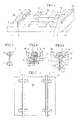
- the base plate 10 to increase the load capacity one of the side parts 9 outgoing and reinforced reinforcement 17, as indicated in FIG. 4 with dash-dotted lines is.
- a rail 2 ' is shown, which instead of one Foot part has a second head part 3 ', so that the rail 2 'after excessive wear, especially on the flange side, removed and reinstalled upside down can.
- Each rail 2 'can thus be used a total of four times Find.
- Fig. 6 shows an arrangement in which the height of the elastomer profile 4 'on the outside of the rail below the head part 3 greater than the height of the elastomer profile 6 'on the inside of the rail is to the deflection of the elastomer profile 6 'and to compensate for the elastomer bands 12.
- the height of the elastomer profile 6 'an inevitable Tilt the rail 2 to the inside as by the second inclined central axis shown in FIG M is indicated, so that the rails are tapered adjust turned treads of a wheel tire and none The flange is worn.
- the rails are 2 in Distances of 10 to 60 m at fixed points rigid with one Foundation 19 connected, as shown in Fig.7.
- the foot part formed as a bead 23 the two elastomer profiles 4 " and 6 "each have a width when removed that equal to half the distance between the two console strips 5 and 7.
- the two elastomer profiles 4 "and 6" can also be formed in one piece by their lower end are connected as shown with dashed lines is. In the transition area are then arranged at a distance Openings 24 are provided which allow an air outlet or air inlet allow when installing and removing the 2 "rail.
- the base plate 10 For street crossings at the same level, that is at least Inner plate 11 executed without opening 16.
- the base plate 10 has in Outline the shape of an isosceles trapezoid while the inner plate 11, each of which is two halves of the base plates 10 overlaps, correspondingly a shape of two in the floor plan composite uneven-legged trapezoids.
- the elastomer bands 12 are first on the Longitudinal ribs of the base plate 10 placed and the rails 2, 2 ' with pliers to the console strips 5 of the base plate 10 pressed, whereupon the inner plate 11, possibly in an inclined position, is used in the base plate 10. Now the elastomer profiles 6, 6 'between the console strips 7 of the inner plate 11 and the rails 2, 2 'inserted in the track direction. Subsequently the rails 2, 2 'from the outside with the pliers pressed together and the elastomer profiles 4, 4 'preferably over the recesses 22 "'between the console strips 5 of the Base plate 10 and the rails 2, 2 'inserted or moved in.
- console strips 5 and 7 or the elastomer profiles 4 and 6 the headboard, bridge and footboard of these profiles can be adjusted.
- the distance between the console strips 5 and 7 to the top of the Base plate 10 is selected so that the foot part 8, 8 'of the rail 2 always, also in the case of load, at a distance from the top the base plate 10 extends.
- the inclination mentioned above the rail 2 can also be achieved in that the distance the console strips 5 on the outside of the rail to the top the base plate 10 is greater than the distance between the console bar 7 on the inside of the rail to the top of the base plate 10 is chosen.
- the foot part by cutting with a cutting torch or laser reduced to the required width on one or both sides becomes.
- the elastomer profiles 4, 4 'and 6, 6' can either be cut to length inserted or used with each plate unit a lubricant inserted over the recesses 22 "' or to be confiscated.
- the upper one Contact surface of the console strips 5, 7 of the base plate 10 and the inner plate 11 substantially parallel to the lower support surface the head part 3 of the rails 2, 3, i.e. aslant, run.
Landscapes
- Engineering & Computer Science (AREA)
- Architecture (AREA)
- Civil Engineering (AREA)
- Structural Engineering (AREA)
- Mechanical Engineering (AREA)
- Railway Tracks (AREA)
- Magnetic Heads (AREA)
- Road Paving Structures (AREA)
- Lock And Its Accessories (AREA)
- Train Traffic Observation, Control, And Security (AREA)
- Golf Clubs (AREA)
- Portable Nailing Machines And Staplers (AREA)
- Diaphragms For Electromechanical Transducers (AREA)
- Vehicle Step Arrangements And Article Storage (AREA)
- Pressure Welding/Diffusion-Bonding (AREA)
- Linear Motors (AREA)
- Supply And Installment Of Electrical Components (AREA)
Abstract
Description
Die Erfindung betrifft ein Gleis, dessen Schienen seitlich und nach unten über elastische Zwischeneinlagen unter dem Kopfteil an der Schienenaußen- und Schieneninnenseite an Längsträgern abgestützt sind, wobei die Schienen mit Abstand über den darunterliegenden Gleisbauteilen verlaufen, und eine sich unter den Schienen erstreckende Basisplatte vorgesehen ist.The invention relates to a track, the rails of which laterally and down over elastic intermediate pads under the Headboard on the inside and outside of the rail Side rails are supported, with the rails at a distance run over the underlying track components, and a extending base plate is provided under the rails.
Zur Verringerung der beim Befahren von Gleisen auftretenden Erschütterungen und des damit erzeugten Körperschalles werden seit längerem elastisch gelagerte Schienen vorgeschlagen. So wird z.B. in der WO 92/04503 ein Gleis-Unterbau beschrieben, bei welchem die Schienen über elastische Zwischenlagen an Profilschienen als Längsträger abgestützt sind, die an der Schienenaußen- und Schieneninnenseite angeordnet und mit darunterliegenden Trägern aus Betonfertigteilen verbunden sind, wobei der Raum unterhalb des Fußteiles der Schiene frei ist. Die Träger sind untereinander durch Querstreben verbunden. Die Profilschienen weisen einen mehrfach gekrümmten Querschnittverlauf auf und sind mittels Schrauben miteinander verspannt, welche durch den Schienensteg hindurchgeführt sind. Der Aufbau dieses Gleises ist somit aufwendig, da eine Mehrzahl von zum Teil kompliziert geformten Bauteilen erforderlich ist, deren Montage auch einen hohen Zeitaufwand erfordert.To reduce the occurrence of tracks Shocks and the structure-borne noise generated with it has been proposed for a long time elastically mounted rails. So e.g. described in WO 92/04503 a track substructure, at which the rails on elastic intermediate layers on profile rails are supported as side members that are attached to the and arranged inside the rail and with underlying Beams made of precast concrete are connected, whereby the space below the foot of the rail is free. The Beams are connected to each other by cross struts. The Profile rails have a multi-curved cross-sectional profile and are clamped together with screws, which are passed through the rail web. The structure this track is therefore complex because a plurality of to Part of complicated shaped components is required, the Assembly also requires a lot of time.
Auch bei einem aus der gattungsbildenden BE 903 871 A bekannten Gleis liegt ein verhältnismäßig komplizierter Aufbau vor, der auch einen hohen Aufwand bei der Montage erfordert. Bei diesem bekannten Gleis sind die Schienen mittels elastischer Zwischenlagen, welche den Kopfteil der Schienen beidseits untergreifen an Längsleisten abgestützt, welche in eine Nut einer Betonplatte eingefügt sind. Diese Betonplatte wird an Ort und Stelle gegossen.Also with a track known from the generic BE 903 871 A. is a relatively complicated structure before, which also requires a lot of effort in assembly. At this known track are the rails by means of elastic Intermediate layers, which the head part of the rails on both sides reach under supported on longitudinal strips, which in a groove a concrete slab are inserted. This concrete slab is in place and poured spot.
Um den Aufwand an Bauteilen und Zeit zu verringern, ist erfindungsgemäß vorgesehen, daß die Längsträger an der Schienenaußenseite erste Konsolenleisten sind, die Teil der sich unter den Schienen erstreckenden Basisplatte sind, und daß die Längsträger an der Schieneninnenseite zweite Konsolenleisten sind, die Teil einer zwischen den Schienen liegenden Innenplatte sind, welche ihrerseits an der Basisplatte abgestützt ist. Die Innenplatte kann als Rahmen ausgebildet sein.To reduce the effort in components and time According to the invention provided that the side members on the Rail outside of the first console strips that are part of the are under the rails extending base plate, and that the Side rails on the inside of the rail, second console strips are part of an inner plate lying between the rails are, which in turn is supported on the base plate. The Inner plate can be designed as a frame.
Eine vorteilhafte Ausführungsform der Erfindung besteht darin, daß die Basisplatte an der Schienenaußenseite nach oben ragende Seitenteile aufweist, an welchen die ersten Konsolenleisten integriert angeordnet sind, und daß die zweiten Konsolenleisten an den seitlichen Enden der Innenplatte oder - rahmen integriert angeordnet sind.An advantageous embodiment of the invention exists in that the base plate on the outside of the rail upwards has protruding side parts on which the first console strips are integrated, and that the second Console strips on the side ends of the inner plate or - frames are integrated.
Um die Belastung der Basisplatten und der Innenplatten gleichmäßig aufzuteilen, und um das Zusammenfallen von Stoßstellen der Basisplatten mit den Stoßstellen der Innenplatten zu vermeiden, kann man vorteilhaft vorsehen, daß die Basisplatte und die Innenplatte gleiche Länge aufweisen und um die halbe Länge versetzt zueinander angeordnet sind.To the load on the base plates and the inner plates to divide evenly, and to collapse joints the base plates with the joints of the inner plates avoid, you can advantageously provide that the base plate and the inner plate have the same length and half Length are offset from each other.
Zur besseren statischen und dynamischen Übertragung von Kräften zwischen Innenplatten und Basisplatten ist es vorteilhaft, wenn die Basisplatte und/oder die Innenplatte zumindest eine Längsrippe zur Abstützung der Innenplatte an der Basisplatte aufweist bzw. aufweisen, wobei vorzugsweise zwischen der Längsrippe der Basisplatte und der Innenplatte oder zwischen einer an der Innenplatte vorgesehenen Längsrippe und der Basisplatte ein Elastomerband angeordnet ist, so daß eine schalldämpfende Wirkung und eine elastische Bettung erzielt wird.For better static and dynamic transmission of Forces between inner plates and base plates, it is advantageous if the base plate and / or the inner plate at least a longitudinal rib to support the inner plate on the base plate has or have, preferably between the Longitudinal rib of the base plate and the inner plate or between a longitudinal rib provided on the inner plate and the base plate an elastomeric band is arranged so that a sound absorbing Effect and an elastic bedding is achieved.
Eine weitere vorteilhafte Ausbildung ist dadurch gekennzeichnet, daß die Basisplatte zwei im Abstand zueinander angeordnete und nach oben gerichtete Längsrippen aufweist, die im Mittenbereich unterbrochen oder in ihrer Höhe vermindert sind, und daß die Innenplatte an ihren Endbereichen zwei mit den Längsrippen der Basisplatte fluchtende Längsrippen aufweist. Hierdurch ist gewährleistet, daß keine gegenseitige Verschiebung der Basis- und Innenplatten in Längsrichtung stattfinden kann.Another advantageous embodiment is characterized in that that the base plate two at a distance from each other arranged and directed upward longitudinal ribs, the interrupted in the middle or reduced in height are, and that the inner plate at its end regions two with the Longitudinal ribs of the base plate have aligned longitudinal ribs. This ensures that there is no mutual displacement the base and inner panels can take place in the longitudinal direction.
Um die Elastomerbänder an den Übergängen zwischen den Längsrippen der jeweiligen Platten nicht zu knicken und in diesem Bereich auch ihre schalldämpfende Wirkung aufrechtzuerhalten, ist es vorteilhaft, wenn die Längsrippen an den wechselseitigen Übergängen zum jeweiligen Plattenkörper der Basisplatte bzw. der Innenplatte schräg verlaufend ausgebildet sind.Around the elastomer bands at the transitions between the longitudinal ribs of the respective plates not to kink and in this area maintain their sound absorbing effect, too it is advantageous if the longitudinal ribs on the mutual Transitions to the respective plate body of the base plate or Inner plate are formed obliquely.
Zweckmäßigerweise sind die Platten zur Gewichts- und Materialeinsparung so gestaltet, daß sowohl die Basisplatte als auch die Innenplatte in der Mitte jeweils mit einer, vorzugsweise rechteckförmigen, Ausnehmung versehen sind, um einen Rahmen zu bilden, wobei gegebenenfalls der Rahmen mit einem geschlossenen Boden versehen ist, um die Festigkeit zu erhöhen.The plates are expedient for weight and Material saving designed so that both the base plate and also the inner plate in the middle with one, preferably rectangular, recess are provided around a Form the frame, where appropriate the frame with a closed bottom is provided to increase the strength.
Bei einer bevorzugten Ausführungsform sind die Basisplatte und die Innenplatte als Fertigteil, vorzugsweise aus Stahl-, Polymer- oder Spezialbeton, ausgebildet, wodurch sich der Kostenaufwand verringert.In a preferred embodiment, the base plate and the inner plate as a finished part, preferably made of steel, Polymer or special concrete, trained, whereby the Reduced costs.
In besonderen Fällen, z.B. bei einem weniger festen oder stark unebenen Untergrund ist es von Vorteil, wenn die Basisplatte in Ortbeton ausgeführt ist.In special cases, e.g. with a less firm or strongly uneven surface, it is advantageous if the Base plate is made of in-situ concrete.
Sowohl die Basisplatte als auch die Innenplatte sind zur Erhöhung ihrer Festigkeit zweckmäßigerweise mit einer Bewehrung versehen, welche schlaff oder vorgespannt sein kann.Both the base plate and the inner plate are for It is advisable to increase its strength with reinforcement provided, which can be limp or biased.
Um das elektrische Potential der Basisplatten festzulegen, sind vorzugsweise am oberen Ende der Seitenteile der Basisplatte längslaufende Profile aus Metall angeordnet, wobei die Profile aufeinanderfolgend liegender Basisplatten elektrisch miteinander verbunden und/oder geerdet sind. Dadurch wird auch zusätzlich die Festigkeit der Basisplatte erhöht.To determine the electrical potential of the base plates, are preferably at the upper end of the side parts of the base plate longitudinal metal profiles arranged, the profiles successively lying base plates electrically with each other connected and / or grounded. This will also add the strength of the base plate increases.
Es können beim Erfindungsgegenstand unterschiedliche Formen von Schienenprofilen eingesetzt werden, und es sind vorzugsweise die Konsolenleisten und die als Elastomerprofile ausgebildeten elastischen Zwischeneinlagen an die Form des Kopfteiles, des Steges und des Fußteiles der Schiene angepaßt.There can be different forms in the subject matter of the invention of rail profiles are used, and they are preferred the console strips and those designed as elastomer profiles elastic intermediate pads to the shape of the headboard, the Web and the foot part of the rail adapted.
Die spezielle Lagerung der Schienen, welche beim Erfindungsgegenstand vorgesehen ist, läßt es vorteilhaft erscheinen, daß die von den Konsolenleisten der Basisplatten und der Innenplatten abgestützten Schienen einen Fußteil haben, der gleich wie der Kopfteil ausgebildet ist. Solcherart kann jede Schiene nach eingetretener Abnützung durch mehrmaliges Wenden insgesamt viermal verwendet werden kann, so daß sich eine lange Gebrauchsdauer ergibt. Es kann erwähnt werden, daß Schienen mit gleich ausgebildetem Kopfteil und Fußteil aus der US 1 260 149 A bekannt sind.The special storage of the rails, which is the subject of the invention is provided, it appears advantageous that that of the console strips of the base plates and the inner plates supported rails have a foot section that is the same how the head part is designed. Any rail can do this after wear and tear by repeated turning a total can be used four times, so that there is a long service life results. It can be mentioned that rails with the same trained head part and foot part from US 1 260 149 A are known.
Bei einer anderen Möglichkeit zum leichteren Einbau der Schienen in die Platten ist es von Vorteil, wenn die Breite des Fußteiles der Schienen gleich groß wie oder kleiner als der Abstand zwischen den ersten und zweiten Konsolenleisten ist.Another possibility for easier installation of the Rails in the panels, it is advantageous if the width of the Foot part of the rails the same size as or smaller than that The distance between the first and second console strips is.
Vorzugsweise sind die Basisplatte und die Innenplatte im Grundriß rechteckförmig ausgebildet und weisen die gleiche Länge auf, wobei die Basisplatte und die Innenplatte in Längsrichtung versetzt zueinander angeordnet sind. Für bogenförmige Gleisstrecken kann man vorteilhaft vorsehen, daß die Basisplatte im Grundriß die Form eines gleichschenkeligen Trapezes aufweist, während die Innenplatte im Grundriß die Form von zwei zusammengesetzten ungleichschenkeligen Trapezen aufweist, welche beide zur Form je der Hälfte einer Basisplatte korrespondierend ausgebildet sind. Preferably, the base plate and the inner plate are in the Floor plan is rectangular and have the same length on, with the base plate and the inner plate in the longitudinal direction are staggered. For curved track sections can advantageously provide that the base plate in Layout has the shape of an isosceles trapezoid, while the inner plate in plan is the shape of two put together has uneven-legged trapezoids, both of which corresponding to the shape of half of a base plate are trained.
Bei kegelig abgedrehten Laufflächen von Radreifen ist es von Vorteil, wenn die Schienen nach innen schräggestellt sind, um sich der Lauffläche anzupassen. Eine bevorzugte Ausführungsform zur Schrägstellung der Schienen ist dadurch gekennzeichnet, daß die Höhe des Elastomerprofils an der Schienenaußenseite unterhalb des Kopfteiles größer als die Höhe des Elastomerprofils an der Schieneninnenseite ist. Eine andere Ausführungsform zur Schrägstellung der Schienen besteht darin, daß der Abstand der Konsolenleiste an der Schienenaußenseite zum oberen Rand der Basisplatte größer als der Abstand der Konsolenleiste an der Schieneninnenseite zum oberen Rand der Innenplatte ist.With tapered treads of wheel tires it is from Advantage if the rails are slanted to the inside adapt to the tread. A preferred embodiment for the inclination of the rails is characterized in that the height of the elastomer profile on the outside of the rail below of the headboard is greater than the height of the elastomer profile the inside of the rail. Another embodiment for Inclination of the rails is that the distance of the Console bar on the outside of the rail to the upper edge of the Base plate larger than the distance of the console bar on the Inside of the rail to the upper edge of the inner plate.
Aus Sicherheits- und Revisionsgründen sieht man vorteilhaft vor, daß in Abständen von 10 bis 60 m Basisplatten, welche als Fertigteile ausgeführt sind, mit einem Fundament starr verbunden sind. Vorzugsweise sind im Fundament Metallplatten verankert, an welchen Befestigungselemente angebracht sind, um die Schienen festzuklemmen.For security and revision reasons one sees advantageous before that at intervals of 10 to 60 m base plates, which as Finished parts are executed, rigidly connected to a foundation are. Metal plates are preferably anchored in the foundation what fasteners are attached to the rails to clamp.
Um den Ein- und Ausbau der Schienen auf einfache Weise vornehmen zu können, sieht man vorzugsweise vor, daß an den Seitenteilen der Basisplatte innenseitig und gegebenenfalls an den Seitenteilen der Innenplatte außenseitig mittige Ausnehmungen vorgesehen sind, wobei die Konsolenleisten und die zugehörigen Elastomerprofile im Bereich der Ausnehmungen unterbrochen sind, so daß das Eindringen eines Werkzeuges, beispielsweise der Backe einer an den Schienen angreifenden Zange, ermöglicht wird.To easily install and remove the rails to be able to make, preferably provides that at the Side parts of the base plate on the inside and if necessary the side parts of the inner plate on the outside central recesses are provided, the console strips and the associated elastomer profiles in the area of the recesses are interrupted so that the penetration of a tool, for example, the jaw of one attacking the rails Pliers, is made possible.
Um die Festigkeit und Tragfähigkeit der Basisplatte zu erhöhen, kann man vorteilhaft an der Basisplatte von den Seitenteilen nach außen gerichtete Verbreiterungen vorsehen.To increase the strength and load capacity of the base plate, can be advantageous on the base plate from the side parts provide outward widening.
Eine hinsichtlich des Einbaues der Schienen besonders günstige Ausführungsform des erfindungsgemäßen Gleises ist dadurch gekennzeichnet, daß der Fußteil der Schienen als Wulst ausgebildet ist und die Elastomerprofile im ausgebauten Zustand jeweils eine Breite aufweisen, die annähernd gleich der Hälfte des Abstands zwischen den beiden Konsolenleisten ist. Man kann solcherart die Schienen relativ einfach zwischen die mit den Elastomerprofilen überdeckten Konsolenleisten einfügen bzw. einschieben, und es sind die Schienen nach Einbau derselben zwischen den Elastomerprofilen durch den Wulst gegen ein nach oben Bewegen gesichert. Es ist dabei für den Einbau auch günstig, wenn man die beiden einer Schiene zugeordneten Elastomerprofile einteilig ausbildet, indem sie an ihrem unteren Ende verbunden sind.One particularly with regard to the installation of the rails favorable embodiment of the track according to the invention characterized in that the foot part of the rails as a bead is formed and the elastomer profiles in the disassembled state each have a width that is approximately equal to half the distance between the two console strips. One can so the rails between the relatively easy with the Insert or insert covered console strips over the elastomer profiles, and it is the rails after installing them between the elastomer profiles by the bead against one after Movement secured above. It is also for installation cheap if you have the two assigned to a rail Forms one-piece elastomer profiles by attaching them to their lower End connected.
Des weiteren kann man zum einfachen Ein- und Ausbau der Schienen vorteilhaft vorsehen, daß an den Seitenteilen der Basisplatte bei den Stoßstellen eine Ausnehmung vorgesehen ist. Zum Einbau der Elastomerprofile wird vorteilhaft vorgesehen, daß an den Seitenteilen der Basisplatte bei den Stoßstellen eine schräge, von außen nach innen durchgehende Ausnehmung vorgesehen ist.Furthermore, you can easily install and remove the Rails advantageously provide that on the side parts of the Base plate at the joints a recess is provided. To install the elastomer profiles, it is advantageously provided that on the side parts of the base plate at the joints oblique recess provided from the outside inwards is.
Um das Laufgeräusch der Räder zu vermindern, ist es von Vorteil, wenn an den Seitenwänden der Basisplatte außen ein- oder beidseitig Wände aus schalldämmendem Material angebracht sind.In order to reduce the running noise of the wheels, it is advantageous if on or in on the side walls of the base plate walls made of sound-absorbing material are attached on both sides.
Weiters ist es von Vorteil, wenn die obere Auflagefläche der Konsolenleisten der Basisplatte und der Innenplatte im wesentlichen parallel zur unteren Auflagefläche des Kopfteiles der Schienen verläuft.Furthermore, it is advantageous if the upper contact surface of the Console strips of the base plate and the inner plate essentially parallel to the lower contact surface of the head part of the Rails runs.
Ein erstes Verfahren zur Montage des Gleises ist
gekennzeichnet durch die Schritte:
Ein zweites Verfahren zur Montage des Gleises ist gekennzeichnet
durch die Schritte:
Ein drittes Verfahren zur Montage des Gleises ist gekennzeichnet
durch die Schritte:
Ein viertes Verfahren zur Montage des Gleises ist gekennzeichnet
durch die Schritte:
Allen Verfahren ist gemeinsam, daß die Montage ohne allzu aufwendiges Einbauwerkzeug in kurzer Zeit durchgeführt werden kann.All methods have in common that the assembly without too much complex installation tools can be carried out in a short time can.
Die Erfindung wird nun nachfolgend anhand von Beispielen
unter Bezugnahme auf die Zeichnung weiter erläutert. In der
Zeichnung zeigen:
In Fig.1 bezeichnet 1 allgemein ein Gleis mit Schienen 2,
deren Kopfteil 3 jeweils an der Schienenaußenseite über ein Elastomerprofil
4 an einer Konsolenleiste 5, und jeweils an der
Schieneninnenseite über ein Elastomerprofil 6 an einer Konsolenleiste
7 abgestützt ist. Die Elastomerprofile 4, 6 erstrecken
sich vom Kopfteil 3 bis zum Fußteil 8, wobei die Elastomerprofile
4, 6 durch die Konsolenleisten 5, 7 zusammengepreßt werden,
so daß die Schienen 2 in seitlicher Richtung fixiert sind.1, 1 generally designates a track with
Die beiden Konsolenleisten 5 an der Schienenaußenseite sind
an nach oben ragenden Seitenteilen 9 einer unter den Schienen 2
liegenden, im Grundriß rechteckförmigen Basisplatte 10
integriert angeordnet. In ähnlicher Weise sind die beiden
Konsolenleisten 7 an der Schieneninnenseite integriert an den
seitlichen Enden einer zwischen den Schienen 2 und oberhalb der
Basisplatte 10 liegenden, im Grundriß rechteckförmigen Innenplatte
11 angeordnet, die sich über Elastomerbänder 12 an der
Basisplatte 10 abstützt. Wie aus Fig.2 und 3 ersichtlich ist,
weisen die Basisplatte 10 und die Innenplatte 11 die gleiche
Länge auf, sind jedoch um eine halbe Länge zueinander versetzt
angeordnet. Um eine gegenseitige Verschiebung der Platten 10, 11
zu verhindern, weist jede Basisplatte 10 zwei im Abstand zueinander
angeordnete und nach oben gerichtete Längsrippen 13
auf, die im Mittenbereich unterbrochen oder in ihrer Höhe vermindert
sind, um eine Ausnehmung für die Aufnahme von Längsrippen
14 an den Endbereichen der Innenplatte 11 zu bilden, die
mit den Längsrippen 13 fluchten und nach unten gerichtet sind,
wobei die Längsrippen 13, 14 an den wechselseitigen Übergängen
zum jeweiligen Plattenkörper der Basisplatte 10 bzw. der Innenplatte
11 schräg verlaufend ausgebildet und in ihrer Höhe so
dimensioniert sind, daß ein Zwischenraum zur Aufnahme der
zwischen den Längsrippen 13, 14 liegenden Elastomerbänder 12
gebildet wird. Durch diese Ausbildung greifen die Längsrippen
13, 14 beim Zusammenbau der Platten 10, 11 in die zwischen den
Längsrippen gebildeten komplementären Vorsprünge und Ausnehmungen
nach Art einer Verzahnung ein und bilden eine formschlüssige
Verbindung in Längsrichtung.The two
Die Basisplatten 10 und die Innenplatten 11 können als
Fertigteile hergestellt werden, wobei bevorzugt Stahlbeton,
Polymerbeton oder Spezialbeton, z.B. mit Zusätzen, verwendet
wird, und die Platten 10, 11 gewünschtenfalls mit einer nicht
dargestellten Bewehrung versehen sein können. Die Basisplatte 10
kann auch in Ortbetonbauweise hergestellt werden. Weiters sind
die Platten 10, 11 zur Einsparung von Material in der Mitte jeweils
mit einer rechteckförmigen Ausnehmung 15 bzw. 16 versehen,
an welche die Längsrippen 13 bzw. 14 seitlich anschließen. Durch
die Ausnehmungen 15 bzw. 16 erhalten die Platten 10, 11 die Form
eines Rahmens, der gegebenenfalls auf der Unterseite mit einem
geschlossenen Boden versehen ist. Des weiteren kann die Basisplatte
10 zur Erhöhung der Tragfähigkeit eine von den Seitenteilen
9 ausgehende und mit einer Bewehrung versehene Verbreiterung
17 aufweisen, wie in Fig.4 mit strichpunktierten Linien angedeutet
ist. Um die Tragfähigkeit der Basisplatte 10 zusätzlich
zu erhöhen, kann der Raum zwischen den beiden Rippen 13 im Bereich
außerhalb der Ausnehmung 15 niveaugleich mit Material ausgefüllt
werden, wie in Fig.4 mit Strich-Zweipunktlinien dargestellt
ist. Die gleiche Maßnahme kann bei der Innenplatte 11
vorgesehen werden.The
Um das elektrische Potential der Basisplatte 10 festzulegen,
sind vorzugsweise am oberen Ende der Seitenteile 9 Winkelprofile
18 aus Metall vorgesehen, die leitend miteinander verbunden
und/oder geerdet werden können.In order to determine the electrical potential of the
In Fig.5 ist eine Schiene 2' dargestellt, welche statt eines Fußteils einen zweiten Kopfteil 3' aufweist, so daß die Schiene 2' nach übermäßigem Verschleiß, insbesondere auf der Spurkranzseite, ausgebaut und verkehrt herum wieder eingesetzt werden kann. Jede Schiene 2' kann somit insgesamt viermal Verwendung finden.In Figure 5, a rail 2 'is shown, which instead of one Foot part has a second head part 3 ', so that the rail 2 'after excessive wear, especially on the flange side, removed and reinstalled upside down can. Each rail 2 'can thus be used a total of four times Find.
Fig.6 zeigt eine Anordnung, bei der die Höhe des Elastomerprofils
4' an der Schienenaußenseite unterhalb des Kopfteiles 3
größer als die Höhe des Elastomerprofils 6' an der Schieneninnenseite
ist, um die Einfederung des Elastomerprofils 6' und
der Elastomerbänder 12 auszugleichen. Gleichzeitig kann durch
geeignete Wahl der Höhe des Elastomerprofils 6' eine zwangsläufige
Schrägstellung der Schiene 2 nach innen erfolgen, wie
durch die zweite in Fig.6 eingezeichnete schräggestellte Mittelachse
M angedeutet ist, so daß sich die Schienen den kegelig
abgedrehten Laufflächen eines Radreifens anpassen und kein
Verschleiß des Spurkranzes erfolgt.Fig. 6 shows an arrangement in which the height of the elastomer profile
4 'on the outside of the rail below the
Aus Sicherheits- und Revisionsgründen sind die Schienen 2 in
Abständen von 10 bis 60 m an Fixpunkten starr mit einem
Fundament 19 verbunden, wie in Fig.7 dargestellt ist.For safety and revision reasons, the rails are 2 in
Distances of 10 to 60 m at fixed points rigid with one
Zur Verbindung der Schienen 2 mit dem Fundament 19 dienen
beispielsweise vier im Fundament verankerte Metallplatten 20, an
welchen herkömmliche Schienenbefestigungselemente 21, z.B.
Klemmplatten, Federklammern oder dergl. angebracht sind, um die
Schienen 2 einzuklemmen. Die Länge des Fundaments kann etwa 0,5
bis 1 m betragen. Durch diese Anordnung wird ein Auswandern der
Schienen 2 in Seiten- und Längsrichtung verhindert.Serve to connect the
Bei der in Fig.8 dargestellten Schiene 2" ist der Fußteil
als Wulst 23 ausgebildet, wobei die beiden Elastomerprofile 4"
und 6" im ausgebauten Zustand jeweils eine Breite aufweisen, die
gleich der Hälfte des Abstandes zwischen den beiden Konsolenleisten
5 und 7 ist. Die beiden Elastomerprofile 4" und 6"
können auch einteilig ausgebildet sein, indem sie an ihrem
unteren Ende verbunden sind, wie mit strichlierten Linien dargestellt
ist. Im Übergangsbereich sind dann im Abstand angeordnete
Öffnungen 24 vorgesehen, die einen Luftaus- bzw. Luftzutritt
beim Ein- und Ausbauen der Schiene 2" ermöglichen.8 is the foot part
formed as a
Für schienengleiche Straßenübergänge ist zumindest die
Innenplatte 11 ohne Durchbrechung 16 ausgeführt. Zur Ausführung
von bogenförmigen Gleisstrecken weist die Basisplatte 10 im
Grundriß die Form eines gleichschenkeligen Trapezes auf, während
die Innenplatte 11, welche jeweils zwei Hälften der Basisplatten
10 überlappt, dementsprechend im Grundriß eine Form von zwei
zusammengesetzten ungleichschenkeligen Trapezen aufweist.For street crossings at the same level, that is at
Zum Einbau der Schienen 2, 2' zwischen Basisplatte 10 und
Innenplatte 11 sind an den Seitenteilen 9 der Basisplatte 10
innenseitig mittige Ausnehmungen 22 vorgesehen, die das Einführen
eines Einbringwerkzeuges, z.B. der Backe einer Zange,
ermöglichen. Zum gleichen Zweck können an der Innenplatte 11
außenseitig Ausnehmungen 22' vorgesehen sein, die in Fig.2 mit
strichlierten Linien dargestellt sind. Zusätzlich können die
Basisplatten 10 bei den Stoßstellen mit einer Ausnehmung 22'
ähnlich der Ausnehmung 22 in der Mitte oder mit breiteren,
schräg verlaufenden Ausnehmungen 22"' versehen sein, wobei
letztere zum leichten Einschieben der Elastomerprofile 4, 4' bei
der Montage dienen (siehe Fig.2). Um ein axiales Wandern der
Elastomerprofile 4, 4' zu verhindern, sind im Bereich der Ausnehmungen
22"' Klemmhalterungen (nicht dargestellt) angeordnet.
Zur Verringerung des Laufgeräusches der Räder können an den
Seitenteilen 9 der Basisplatte 10 Wände 25 aus schalldämmendem
Material ein- oder beidseitig angebracht werden (Siehe Fig.2).
Im Bereich der Ausnehmungen 22 sind die Elastomerprofile 4, 4'
und die Konsolenleisten 5, 5' unterbrochen.To install the
Beim Einbau werden zuerst die Elastomerbänder 12 auf die
Längsrippen der Basisplatte 10 aufgelegt und die Schienen 2, 2'
mit einer Zange an die Konsolenleisten 5 der Basisplatte 10
angepreßt, worauf die Innenplatte 11, eventuell in Schräglage,
in die Basisplatte 10 eingesetzt wird. Nun werden die Elastomerprofile
6, 6' zwischen den Konsolenleisten 7 der Innenplatte 11
und den Schienen 2, 2' in Gleisrichtung eingeschoben. Anschließend
werden die Schienen 2, 2' von außen mit der Zange
zusammengepreßt und die Elastomerprofile 4, 4' vorzugsweise über
die Ausnehmungen 22"' zwischen den Konsolenleisten 5 der
Basisplatte 10 und den Schienen 2, 2' eingeschoben oder
eingezogen.When installing, the
Bei einer zweiten Art des Einbauens werden zuerst die
Elastomerprofile 6, 6' an den Konsolenleisten 7 der Innenplatte
11 angebracht und anschließend die Schienen 2, 2' außen an die
Elastomerprofile 6, 6' angelegt. Dann werden die Schienen 2, 2'
von außen mittels der Zange zusammengepreßt, so daß sich der
Abstand der Schienen zueinander verringert. Anschließend wird
diese Baugruppe zwischen die Konsolenleisten 5 der Basisplatte
10 eingesetzt, in welcher zuvor die Elastomerbänder 12 auf die
Längsrippen 13 gelegt wurden, wobei die Zangenbacken in die
Ausnehmungen 22 eintreten, worauf die Elastomerprofile 4, 4' an
den Konsolenleisten 5 der Basisplatte 10 durch Einschieben
angebracht werden. Nach Freigabe der Zange sind die Schienen 2,
2' eingespannt, worauf die Zangenbacken aus den Ausnehmungen 22
herausgezogen werden. In a second type of installation, the
Elastomer profiles 6, 6 'on the console strips 7 of the
Eine dritte Art des Einbauens der Schiene 2" nach Fig.8 besteht
darin, daß zuerst die Elastomerbänder eingelegt und die
Innenplatten 11 in die Basisplatte 10 eingesetzt wird, anschließend
die Schienen 2" beidseitig mit den Elastomerprofilen
4, 4' bzw. 6, 6' versehen werden, worauf diese Baueinheit gegebenenfalls
unter Zwischenlage eines Blechstreifens zwischen die
Konsolenleisten 5 bzw. 7 unter Druck von oben eingepreßt werden.A third way of installing the
Eine vierte Art des Einbauens der Schienen 2" nach Fig.8 besteht
darin, daß zuerst die Elastomerprofile 4, 4' bzw. 6, 6' an
den Konsolenleisten 5 bzw. 7 angebracht werden, worauf die
Schienen 2" unter Druck von oben eingepreßt und durch den Wulst
23 in dieser Lage gesichert werden.A fourth way of installing the
Da es verschiedene Formen von Schienenprofilen gibt, können
die Konsolenleisten 5 und 7 bzw. die Elastomerprofile 4 und 6 an
den Kopfteil, Steg und Fußteil dieser Profile angepaßt werden.Since there are different shapes of rail profiles, you can
the console strips 5 and 7 or the
Der Abstand der Konsolenleisten 5 bzw. 7 zur Oberseite der
Basisplatte 10 ist so gewählt, daß der Fußteil 8, 8' der Schiene
2 stets, also auch im Belastungsfall, im Abstand zur Oberseite
der Basisplatte 10 verläuft. Die oben erwähnte Schrägstellung
der Schiene 2 kann auch dadurch erreicht werden, daß der Abstand
der Konsolenleisten 5 an der Schienenaußenseite zur Oberseite
der Basisplatte 10 größer als der Abstand der Konsolenleiste 7
an der Schieneninnenseite zur Oberseite der Basisplatte 10
gewählt wird.The distance between the console strips 5 and 7 to the top of the
Zur Herstellung von Schienen mit verminderter Breite des Fußteiles können Schienen mit Normalprofil verwendet werden, deren Fußteil durch Schneiden mittels Schneidbrenner oder Laser ein- oder beidseitig auf die erforderliche Breite reduziert wird.For the production of rails with reduced width of the Rails with normal profile can be used, the foot part by cutting with a cutting torch or laser reduced to the required width on one or both sides becomes.
Die Elastomerprofile 4, 4' bzw. 6, 6' können entweder abgelängt
bei jeder Platteneinheit eingeschoben oder unter Verwendung
eines Gleitmittels über die Ausnehmungen 22"' eingeschoben
oder eingezogen werden.The elastomer profiles 4, 4 'and 6, 6' can either be cut to length
inserted or used with each plate unit
a lubricant inserted over the
Aus Gründen der günstigeren Druckverteilung kann die obere
Auflagefläche der Konsolenleisten 5, 7 der Basisplatte 10 und
der Innenplatte 11 im wesentlichen parallel zur unteren Auflagefläche
des Kopfteiles 3 der Schienen 2, 3, d.h. schräg,
verlaufen.For reasons of more favorable pressure distribution, the upper one
Contact surface of the console strips 5, 7 of the
Claims (33)
- A track the rails (2) of which are laterally and downwardly supported on the rail outer side and on the rail inner side via elastic intermediate inserts (4, 6) by longitudinal carriers underneath the head portion (3), the rails extending at a distance above the track structure parts located therebelow, and a base plate extending below the rails being provided, characterized in that the longitudinal carriers on the rail outer side are first console ledges (5) which are part of the base plate (10) extending under the rails (2; 2'; 2"), and that the longitudinal carriers on the rail inner side are second console ledges (7) which are part of an inner plate (11) lying between the rails (2; 2'; 2"), which inner plate (11) in turn is supported on the base plate (10).
- A track according to claim 1, characterized in that on the rail outer side, the base plate (10) comprises upwardly projecting side portions (9), on which the first console ledges (5) are integrally arranged, and that the second console ledges (7) are integrally arranged at the lateral ends of the inner plate (11).
- A track according to claim 1 or 2, characterized in that the base plate (10) and the inner plate (11) have equal lengths and are arranged to be longitudinally offset relative to each other.
- A track according to one or several of claims 1 to 3, characterized in that the base plate (10) and/or the inner plate (11) comprise(s) at least one longitudinal rib (13, 14) for supporting the inner plate (11) on the base plate (10).
- A track according to claim 4, characterized in that an elastomer strip (12) is arranged between the longitudinal rib (13, 14) of the base plate (10) and the inner plate (11), or between a longitudinal rib provided on the inner plate and the base plate.
- A track according to claim 4 or 5, characterized in that the base plate (10) comprises two upwardly directed longitudinal ribs (13) arranged at a distance from each other, the middle region of said longitudinal ribs being interrupted or of a reduced height, and that the inner plate (11) at its end regions includes two longitudinal ribs (14) which register with the longitudinal ribs (13) of the base plate (10).
- A track according to claim 6, characterized in that the longitudinal ribs (13, 14) at the mutual transitions to the respective plate body of the base plate (10) or of the inner plate (11) are designed to be chamfered.
- A track according to one or several of claims 1 to 7, characterized in that both the base plate (10) and the inner plate (11) in their middle are each provided with a preferably rectangle-shaped recess (15, 16) so as to form a frame.
- A track according to claim 8, characterized in that the frame is provided with a closed bottom.
- A track according to one or several of claims 1 to 9, characterized in that the base plate (10) and the inner plate (11) are designed as a prefabricated part, preferably made of ferroconcrete, polymer bonded concrete, or special concrete.
- A track according to one or several of claims 1 to 9, characterized in that the base plate (10) is made of site-mixed concrete.
- A track according to claim 10 or 11, characterized in that the base plate (10) and the inner plate (11) are provided with a reinforcement.
- A track according to claim 2, characterized in that preferably on the upper end of the side portions (9) of the base plate (10), longitudinally extending metal sections (18) are arranged, wherein the sections of successively arranged base plates (10) are electrically interconnected and/or connected to ground.
- A track according to any one of claims 1 to 13, characterized in that the console ledges (5, 7; 5', 7') and the elastic intermediate inserts designed as elastomer sections (4, 6; 4', 6') are adapted to the shape of the head portion, the web and the foot portion of the rail (2; 2').
- A track according to any one of the preceding claims, characterized in that the rails (2') supported by the console ledges (5, 7; 5', 7') of the base plates (10) and of the inner plates (11) have a foot portion (3') designed in conformity to the head portion (3).
- A track according to claim 15, characterized in that the width of the foot portion (8; 23) of the rails (2; 2") is equal to or smaller than the distance between the first and the second console ledges (5, 7).
- A track according to any one of claims 1 to 16, characterized in that the base plate (10) and the inner plate (11) are designed to have a rectangle-shaped ground plan and have equal lengths, the base plate (10) and the inner plate (11) being arranged to be longitudinally offset relative to each other.
- A track according to claim 10, characterized in that the ground plan of the base plate (10') has the shape of a isosceles trapezoid, and that the ground plan of the inner plate (11') has the shape of two assembled non-isosceles trapezoids, which are both designed to correspond to the shape of one half of the base plate (10) each.
- A track according to claim 1 or 2, characterized in that the height of the elastomer section (4') at the rail outer side below the head portion (3) exceeds the height of the elastomer section (6') at the rail inner side.
- A track according to claim 1 or 2, characterized in that the distance of the console ledge (5') at the rail outer side to the upper edge of the base plate (10) exceeds the distance of the console ledge (7') on the rail inner side to the upper edge of the inner plate (11).
- A track according to claim 1, characterized in that the base plates (10), which are prefabricated parts, are rigidly connected to a base (19) at intervals of from 10 to 60 m.
- A track according to claim 21, characterized in that metal plates (20) are anchored on the base plates (10) connected with a base (19) or directly on the base (19), and rail fastening elements (21) being attached to said metal plates (20).
- A track according to claim 2, characterized in that central recesses (22; 22') are provided on the inner side of the side portions (9) of the base plate (10) and, optionally, on the outer side of the side portions of the inner plate (11), the console ledges (5) and the associated elastomer sections (6; 6') being interrupted in the region of the recesses (22).
- A track according to claim 2, characterized in that the base plate (10) comprises a broadening portion (17) departing from the side portions (9).
- A track according to claim 18, characterized in that the foot portion (8) of the rails (2") is designed as a bead (23), the elastomer sections (4", 6") in the disassembled state each having a width corresponding to half the distance between the two console ledges (5, 7).
- A track according to claim 2, characterized in that a recess (22") is provided on the side portions (9) of the base plate (10) at the sites of abutment.
- A track according to claim 2, characterized in that a slanted recess (22"') extending from the outside to the inside, is provided on the side portions (9) of the base plate (10) at the sites of abutment.
- A track according to claim 2, characterized in that walls (25) of sound-absorbing material are attached externally to one or both sides of the side walls (9) of the base plate (10).
- A track according to claim 2, characterized in that the upper seat-engaging surfaces of the console ledges (5, 7) of the base plate (10) and of the inner plate (11) extend substantially in parallel to the lower seat-engaging surface of the head portion (3) of the rails (2; 2'; 2").
- A method of mounting a track according to any one of claims 1 to 29, characterized by the steps of:a) laying elastomer strips (12) onto longitudinal ribs (13) of the base plate (10), and laying the rails (2, 2') against the console ledges (5) of the base plate (10),b) inserting the inner plate (11) on the one side of the base plate (10) in a skew manner, and inwardly pivoting the inner plate (11) on the other side into the base plate (10),c) sliding-in elastomer sections (6, 6') between the console ledges (7) of the inner plate (11) and the rails (2, 2'),d) pressing together the rails (2, 2') from the outside, and inserting the elastomer sections (4, 4') between the console ledges (5) of the base plate (10) and the rails (2, 2'),e) releasing the tension of the rails (2, 2') towards the outer side so that the rails (2, 2') are braced between the elastomer sections provided on the console ledges (5, 7).
- A method of mounting a track according to any one of claims 1 to 29, characterized by the steps of:a) attaching elastomer sections (6, 6') to the console ledges (7, 7') of the inner plate (11) and laying the rails (2, 2') against the elastomer sections (6, 6'),b) pressing the rails (2, 2') together from the outside,c) laying elastomer strips (12) onto longitudinal ribs (13) of the base plate (10), and inserting the rails (2, 2') together with the inner plate (11) into the base plate (10),d) sliding-in elastomer sections (4, 4') between the console ledges (5) of the base plate (10) and the rails (2, 2'), ande) releasing the tension of the rails (2, 2') towards the outer side so that the rails (2, 2') are braced between the elastomer sections provided on the console ledges (5, 7).
- A method of mounting a track according to any one of claims 1 to 29, characterized by the steps of:a) laying elastomer strips (12) on longitudinal ribs (13) of the base plate (10) and inserting the inner plate (11) in the base plate (10),b) attaching elastomer sections (4, 4', 6, 6') to both sides of the rails (2, 2'), andc) pressing-in the rails (2, 2') together with the elastomer sections (4, 4', 6, 6') between the console ledges (5, 5') of the base plate (10) and the console ledges (7, 7') of the inner plate (11), optionally with a metal sheet strip interposed between the console ledges (5, 5', 7, 7').
- A method of mounting a track according to any one of claims 1 to 28, characterized by the steps of:a) laying elastomer strips (12) onto longitudinal ribs (13) of the base plate (10) and inserting the inner plate (11) in the base plate (10),b) inserting elastomer sections (4", 6") between the console ledges (5, 5') of the base plate (10) and the console ledges (7, 7') of the inner plate (11), andc) pressing-in the rails (2").
Applications Claiming Priority (4)
| Application Number | Priority Date | Filing Date | Title |
|---|---|---|---|
| AT24339/49 | 1994-12-30 | ||
| AT2433/94 | 1994-12-30 | ||
| AT0243394A AT403386B (en) | 1994-12-30 | 1994-12-30 | TRACK |
| PCT/AT1995/000252 WO1996021063A1 (en) | 1994-12-30 | 1995-12-22 | Railway track |
Publications (2)
| Publication Number | Publication Date |
|---|---|
| EP0800599A1 EP0800599A1 (en) | 1997-10-15 |
| EP0800599B1 true EP0800599B1 (en) | 1998-05-20 |
Family
ID=3534267
Family Applications (1)
| Application Number | Title | Priority Date | Filing Date |
|---|---|---|---|
| EP95940079A Expired - Lifetime EP0800599B1 (en) | 1994-12-30 | 1995-12-22 | Railway track |
Country Status (16)
| Country | Link |
|---|---|
| US (1) | US5806764A (en) |
| EP (1) | EP0800599B1 (en) |
| JP (1) | JP3602137B2 (en) |
| KR (1) | KR100405939B1 (en) |
| CN (1) | CN1096530C (en) |
| AT (2) | AT403386B (en) |
| AU (1) | AU699601B2 (en) |
| CZ (1) | CZ145497A3 (en) |
| DE (1) | DE59502289D1 (en) |
| ES (1) | ES2118643T3 (en) |
| FI (1) | FI119776B (en) |
| HU (1) | HU218774B (en) |
| NO (1) | NO309106B1 (en) |
| PL (1) | PL178301B1 (en) |
| SK (1) | SK78597A3 (en) |
| WO (1) | WO1996021063A1 (en) |
Families Citing this family (7)
| Publication number | Priority date | Publication date | Assignee | Title |
|---|---|---|---|---|
| DE19920075A1 (en) * | 1999-05-03 | 2000-12-07 | Boegl Max Bauunternehmung Gmbh | Rail mounting system comprises profiles which support rail on each side and rail bed with ramp section contacting one profiles, third profile contacting other profile and other side of rail bed and being fastened to bed with bolts |
| DE19920146B4 (en) * | 1999-05-03 | 2005-07-21 | Max Bögl Bauunternehmung GmbH & Co. KG | Storage of a rail for rail vehicles |
| NL1012649C2 (en) * | 1999-07-20 | 2001-01-23 | Grimbergen Holding B V | Track plate for a rail track, and method of attachment thereto. |
| KR100711202B1 (en) | 2005-12-10 | 2007-04-24 | 송억영 | Central guide single rail track tramcar |
| AU2007260579B2 (en) * | 2006-06-13 | 2012-09-06 | Newstyle Nominees Pty Ltd | Rail track crossing |
| DE102006043745A1 (en) * | 2006-09-13 | 2008-04-03 | Max Bögl Bauunternehmung GmbH & Co. KG | Track and method of making a track |
| FR2938274B1 (en) * | 2008-11-10 | 2016-02-05 | Alstom Transport Sa | BALLAST FIXED TRACK SUPERSTRUCTURE WITH FOUNDATION SLAB SECTIONAL |
Family Cites Families (15)
| Publication number | Priority date | Publication date | Assignee | Title |
|---|---|---|---|---|
| US1260149A (en) * | 1917-10-13 | 1918-03-19 | William G Coughlin | Railroad-rail and support. |
| US1587691A (en) * | 1924-10-23 | 1926-06-08 | Richard A Whittingham | Railway-track structure |
| AT227289B (en) * | 1961-01-20 | 1963-05-10 | Meteoor Nv Betonfabriek | Track storage on block sleepers |
| US3525472A (en) * | 1966-08-30 | 1970-08-25 | Japan National Railway | Vibration-suppressing composite rail for railways |
| JPS5251605A (en) * | 1975-10-24 | 1977-04-25 | Yutaka Sato | Rail viebration insulating and tighteing device |
| DE2817278C3 (en) * | 1978-04-20 | 1980-10-30 | Diether 4300 Essen Uderstaedt | Sound-absorbing rail pad |
| GB2024289B (en) * | 1978-06-30 | 1983-03-30 | Clouth Gummiwerke Ag | Resilient rail support |
| AT367482B (en) * | 1980-05-20 | 1982-07-12 | Hoetzel Beton Gmbh | RAILWAY RAILWAY TRANSITION WITH CONCRETE INTERNAL PANELS |
| US4616395A (en) * | 1983-06-30 | 1986-10-14 | Perini Corporation | Railroad track fixation method and apparatus |
| DE3536966A1 (en) * | 1985-10-17 | 1987-04-23 | Uderstaedt Diether | RAIL BASE |
| DE3540128A1 (en) * | 1985-11-13 | 1987-05-14 | Clouth Gummiwerke Ag | ELASTIC BEARING RAIL FOR RAIL VEHICLES |
| BE903871A (en) * | 1985-12-17 | 1986-04-16 | Dynamit Du Batiment En Abrege | Antivibration rail track system - has continuous elastic rail support with head and core inserted in grooves in concrete |
| DE4007937C2 (en) * | 1990-03-13 | 2002-03-21 | Hermann Ortwein | Elastic rail for rail vehicles |
| DE4114803A1 (en) * | 1991-05-07 | 1992-11-12 | Hermann Ortwein | Grooved travel rail with frame - has height only slightly greater than width of head |
| DE4311452C2 (en) * | 1993-04-07 | 2000-03-09 | Wuerzburger Strassenbahn Gmbh | Elastic rail bearing with open or closed superstructure for rail vehicles |
-
1994
- 1994-12-30 AT AT0243394A patent/AT403386B/en not_active IP Right Cessation
-
1995
- 1995-12-22 CZ CZ971454A patent/CZ145497A3/en unknown
- 1995-12-22 KR KR1019970704353A patent/KR100405939B1/en not_active Expired - Fee Related
- 1995-12-22 JP JP52063296A patent/JP3602137B2/en not_active Expired - Fee Related
- 1995-12-22 DE DE59502289T patent/DE59502289D1/en not_active Expired - Lifetime
- 1995-12-22 ES ES95940079T patent/ES2118643T3/en not_active Expired - Lifetime
- 1995-12-22 EP EP95940079A patent/EP0800599B1/en not_active Expired - Lifetime
- 1995-12-22 PL PL95320997A patent/PL178301B1/en not_active IP Right Cessation
- 1995-12-22 AU AU41678/96A patent/AU699601B2/en not_active Ceased
- 1995-12-22 HU HU9701738A patent/HU218774B/en not_active IP Right Cessation
- 1995-12-22 SK SK785-97A patent/SK78597A3/en unknown
- 1995-12-22 AT AT95940079T patent/ATE166405T1/en active
- 1995-12-22 CN CN95197065A patent/CN1096530C/en not_active Expired - Fee Related
- 1995-12-22 WO PCT/AT1995/000252 patent/WO1996021063A1/en not_active Ceased
- 1995-12-22 US US08/702,588 patent/US5806764A/en not_active Expired - Lifetime
-
1997
- 1997-06-27 FI FI972782A patent/FI119776B/en not_active IP Right Cessation
- 1997-06-30 NO NO973053A patent/NO309106B1/en not_active IP Right Cessation
Also Published As
| Publication number | Publication date |
|---|---|
| NO973053D0 (en) | 1997-06-30 |
| PL178301B1 (en) | 2000-04-28 |
| WO1996021063A1 (en) | 1996-07-11 |
| ES2118643T3 (en) | 1998-09-16 |
| HU218774B (en) | 2000-12-28 |
| FI119776B (en) | 2009-03-13 |
| AU699601B2 (en) | 1998-12-10 |
| ATE166405T1 (en) | 1998-06-15 |
| CN1096530C (en) | 2002-12-18 |
| HUT76961A (en) | 1998-01-28 |
| KR100405939B1 (en) | 2004-04-29 |
| CZ145497A3 (en) | 1997-08-13 |
| US5806764A (en) | 1998-09-15 |
| ATA243394A (en) | 1997-06-15 |
| CN1171139A (en) | 1998-01-21 |
| FI972782A0 (en) | 1997-06-27 |
| AT403386B (en) | 1998-01-26 |
| EP0800599A1 (en) | 1997-10-15 |
| AU4167896A (en) | 1996-07-24 |
| JP3602137B2 (en) | 2004-12-15 |
| NO973053L (en) | 1997-06-30 |
| JPH10511754A (en) | 1998-11-10 |
| NO309106B1 (en) | 2000-12-11 |
| SK78597A3 (en) | 1998-01-14 |
| PL320997A1 (en) | 1997-11-24 |
| DE59502289D1 (en) | 1998-06-25 |
| FI972782L (en) | 1997-06-27 |
Similar Documents
| Publication | Publication Date | Title |
|---|---|---|
| EP0420882A1 (en) | Rail for vehicles. | |
| DD291792A5 (en) | CHASSIS CARRIER FOR MAGNETIC RAILWAYS | |
| DE202009018663U1 (en) | Device for bridging expansion joints and profile construction | |
| EP0800599B1 (en) | Railway track | |
| DE19920858C2 (en) | Superstructure points device | |
| DE2123225A1 (en) | Compound expansion joint | |
| EP1165968A1 (en) | Height-adjustable support arranged between two parallel plates | |
| DE69619195T2 (en) | Rail device, in particular for bridges and viaducts | |
| EP0198158B1 (en) | Resilient rail support | |
| EP0853706B1 (en) | Level crossing | |
| DE60009330T2 (en) | DEVICE AND METHOD FOR FASTENING A FLAT ELEMENT TO A VEHICLE | |
| DE4425037C1 (en) | Road joint for expansion joints in bridges etc. | |
| EP1573133B1 (en) | Frame sleeper and method for the production thereof | |
| EP1114221A1 (en) | Sleeper frame for a rail system for rail-mounted vehicles, especially for a ballasted track | |
| EP1914347B1 (en) | level crossing device | |
| DE19920146B4 (en) | Storage of a rail for rail vehicles | |
| AT394009B (en) | TRACK BRAKE ELEMENT | |
| AT393850B (en) | BRIDGE DEVICE FOR EXPANSION JOINTS IN ROADS OF BRIDGES OD. DGL. | |
| EP1232084B1 (en) | Aluminum large-profile main stretcher for rail vehicles | |
| EP0456639B1 (en) | Device for covering and sealing expansion gaps, particularly in roadways | |
| DE1534108A1 (en) | Track construction | |
| EP1800986B1 (en) | Linking system for a wall or floor structure | |
| DE69204672T2 (en) | FRAME PART FOR A VEHICLE. | |
| WO2005078195A2 (en) | Tie for a ballasted track | |
| DE2435748A1 (en) | Raised rectangular-panelled intermediate floor - on corner supports leaving open space underneath with connectors detachable for panel removal |
Legal Events
| Date | Code | Title | Description |
|---|---|---|---|
| PUAI | Public reference made under article 153(3) epc to a published international application that has entered the european phase |
Free format text: ORIGINAL CODE: 0009012 |
|
| 17P | Request for examination filed |
Effective date: 19970705 |
|
| AK | Designated contracting states |
Kind code of ref document: A1 Designated state(s): AT BE CH DE DK ES FR GB GR IE IT LI LU NL PT SE |
|
| AX | Request for extension of the european patent |
Free format text: SI PAYMENT 970705 |
|
| GRAG | Despatch of communication of intention to grant |
Free format text: ORIGINAL CODE: EPIDOS AGRA |
|
| GRAG | Despatch of communication of intention to grant |
Free format text: ORIGINAL CODE: EPIDOS AGRA |
|
| GRAH | Despatch of communication of intention to grant a patent |
Free format text: ORIGINAL CODE: EPIDOS IGRA |
|
| 17Q | First examination report despatched |
Effective date: 19971017 |
|
| GRAH | Despatch of communication of intention to grant a patent |
Free format text: ORIGINAL CODE: EPIDOS IGRA |
|
| GRAA | (expected) grant |
Free format text: ORIGINAL CODE: 0009210 |
|
| AK | Designated contracting states |
Kind code of ref document: B1 Designated state(s): AT BE CH DE DK ES FR GB GR IE IT LI LU NL PT SE |
|
| AX | Request for extension of the european patent |
Free format text: SI PAYMENT 970705 |
|
| PG25 | Lapsed in a contracting state [announced via postgrant information from national office to epo] |
Ref country code: NL Free format text: LAPSE BECAUSE OF FAILURE TO SUBMIT A TRANSLATION OF THE DESCRIPTION OR TO PAY THE FEE WITHIN THE PRESCRIBED TIME-LIMIT Effective date: 19980520 Ref country code: GR Free format text: LAPSE BECAUSE OF NON-PAYMENT OF DUE FEES Effective date: 19980520 |
|
| REF | Corresponds to: |
Ref document number: 166405 Country of ref document: AT Date of ref document: 19980615 Kind code of ref document: T |
|
| REG | Reference to a national code |
Ref country code: CH Ref legal event code: EP |
|
| REF | Corresponds to: |
Ref document number: 59502289 Country of ref document: DE Date of ref document: 19980625 |
|
| ITF | It: translation for a ep patent filed | ||
| REG | Reference to a national code |
Ref country code: CH Ref legal event code: NV Representative=s name: A. BRAUN, BRAUN, HERITIER, ESCHMANN AG PATENTANWAE |
|
| GBT | Gb: translation of ep patent filed (gb section 77(6)(a)/1977) |
Effective date: 19980724 |
|
| PG25 | Lapsed in a contracting state [announced via postgrant information from national office to epo] |
Ref country code: DK Free format text: LAPSE BECAUSE OF FAILURE TO SUBMIT A TRANSLATION OF THE DESCRIPTION OR TO PAY THE FEE WITHIN THE PRESCRIBED TIME-LIMIT Effective date: 19980820 |
|
| REG | Reference to a national code |
Ref country code: IE Ref legal event code: FG4D Free format text: GERMAN |
|
| REG | Reference to a national code |
Ref country code: ES Ref legal event code: FG2A Ref document number: 2118643 Country of ref document: ES Kind code of ref document: T3 |
|
| ET | Fr: translation filed | ||
| NLV1 | Nl: lapsed or annulled due to failure to fulfill the requirements of art. 29p and 29m of the patents act | ||
| REG | Reference to a national code |
Ref country code: PT Ref legal event code: SC4A Free format text: AVAILABILITY OF NATIONAL TRANSLATION Effective date: 19980817 |
|
| PG25 | Lapsed in a contracting state [announced via postgrant information from national office to epo] |
Ref country code: IE Free format text: LAPSE BECAUSE OF NON-PAYMENT OF DUE FEES Effective date: 19981211 |
|
| PG25 | Lapsed in a contracting state [announced via postgrant information from national office to epo] |
Ref country code: LU Free format text: LAPSE BECAUSE OF NON-PAYMENT OF DUE FEES Effective date: 19981222 |
|
| REG | Reference to a national code |
Ref country code: IE Ref legal event code: FD4D |
|
| PG25 | Lapsed in a contracting state [announced via postgrant information from national office to epo] |
Ref country code: BE Free format text: LAPSE BECAUSE OF NON-PAYMENT OF DUE FEES Effective date: 19981231 |
|
| PLBE | No opposition filed within time limit |
Free format text: ORIGINAL CODE: 0009261 |
|
| STAA | Information on the status of an ep patent application or granted ep patent |
Free format text: STATUS: NO OPPOSITION FILED WITHIN TIME LIMIT |
|
| 26N | No opposition filed | ||
| BERE | Be: lapsed |
Owner name: GMUNDNER FERTIGTEILE G.M.B.H. & CO. K.G. Effective date: 19981231 |
|
| REG | Reference to a national code |
Ref country code: GB Ref legal event code: IF02 |
|
| REG | Reference to a national code |
Ref country code: CH Ref legal event code: PFA Owner name: GMUNDNER FERTIGTEILE GESELLSCHAFT M.B.H. & CO. KG Free format text: GMUNDNER FERTIGTEILE GESELLSCHAFT M.B.H. & CO. KG.#KUFERZEILE 30-32#A-4810 GMUNDEN (AT) -TRANSFER TO- GMUNDNER FERTIGTEILE GESELLSCHAFT M.B.H. & CO. KG.#KUFERZEILE 30-32#A-4810 GMUNDEN (AT) |
|
| PGFP | Annual fee paid to national office [announced via postgrant information from national office to epo] |
Ref country code: SE Payment date: 20111219 Year of fee payment: 17 Ref country code: PT Payment date: 20110930 Year of fee payment: 17 Ref country code: FR Payment date: 20111018 Year of fee payment: 17 Ref country code: ES Payment date: 20111115 Year of fee payment: 17 |
|
| PGFP | Annual fee paid to national office [announced via postgrant information from national office to epo] |
Ref country code: CH Payment date: 20121224 Year of fee payment: 18 |
|
| PGFP | Annual fee paid to national office [announced via postgrant information from national office to epo] |
Ref country code: GB Payment date: 20121123 Year of fee payment: 18 Ref country code: IT Payment date: 20121207 Year of fee payment: 18 |
|
| PGFP | Annual fee paid to national office [announced via postgrant information from national office to epo] |
Ref country code: AT Payment date: 20121220 Year of fee payment: 18 |
|
| PGFP | Annual fee paid to national office [announced via postgrant information from national office to epo] |
Ref country code: DE Payment date: 20130227 Year of fee payment: 18 |
|
| REG | Reference to a national code |
Ref country code: PT Ref legal event code: MM4A Free format text: LAPSE DUE TO NON-PAYMENT OF FEES Effective date: 20130624 |
|
| PG25 | Lapsed in a contracting state [announced via postgrant information from national office to epo] |
Ref country code: SE Free format text: LAPSE BECAUSE OF NON-PAYMENT OF DUE FEES Effective date: 20121223 |
|
| PG25 | Lapsed in a contracting state [announced via postgrant information from national office to epo] |
Ref country code: PT Free format text: LAPSE BECAUSE OF NON-PAYMENT OF DUE FEES Effective date: 20130624 |
|
| REG | Reference to a national code |
Ref country code: FR Ref legal event code: ST Effective date: 20130830 |
|
| PG25 | Lapsed in a contracting state [announced via postgrant information from national office to epo] |
Ref country code: FR Free format text: LAPSE BECAUSE OF NON-PAYMENT OF DUE FEES Effective date: 20130102 |
|
| REG | Reference to a national code |
Ref country code: ES Ref legal event code: FD2A Effective date: 20140307 |
|
| PG25 | Lapsed in a contracting state [announced via postgrant information from national office to epo] |
Ref country code: ES Free format text: LAPSE BECAUSE OF NON-PAYMENT OF DUE FEES Effective date: 20121223 |
|
| REG | Reference to a national code |
Ref country code: DE Ref legal event code: R119 Ref document number: 59502289 Country of ref document: DE |
|
| REG | Reference to a national code |
Ref country code: CH Ref legal event code: PL |
|
| REG | Reference to a national code |
Ref country code: AT Ref legal event code: MM01 Ref document number: 166405 Country of ref document: AT Kind code of ref document: T Effective date: 20131222 |
|
| GBPC | Gb: european patent ceased through non-payment of renewal fee |
Effective date: 20131222 |
|
| REG | Reference to a national code |
Ref country code: DE Ref legal event code: R119 Ref document number: 59502289 Country of ref document: DE Effective date: 20140701 |
|
| PG25 | Lapsed in a contracting state [announced via postgrant information from national office to epo] |
Ref country code: DE Free format text: LAPSE BECAUSE OF NON-PAYMENT OF DUE FEES Effective date: 20140701 Ref country code: CH Free format text: LAPSE BECAUSE OF NON-PAYMENT OF DUE FEES Effective date: 20131231 Ref country code: LI Free format text: LAPSE BECAUSE OF NON-PAYMENT OF DUE FEES Effective date: 20131231 |
|
| PG25 | Lapsed in a contracting state [announced via postgrant information from national office to epo] |
Ref country code: GB Free format text: LAPSE BECAUSE OF NON-PAYMENT OF DUE FEES Effective date: 20131222 Ref country code: AT Free format text: LAPSE BECAUSE OF NON-PAYMENT OF DUE FEES Effective date: 20131222 |
|
| PG25 | Lapsed in a contracting state [announced via postgrant information from national office to epo] |
Ref country code: IT Free format text: LAPSE BECAUSE OF NON-PAYMENT OF DUE FEES Effective date: 20131222 |