EP0758434B1 - Systeme d'embrayage - Google Patents
Systeme d'embrayage Download PDFInfo
- Publication number
- EP0758434B1 EP0758434B1 EP95919362A EP95919362A EP0758434B1 EP 0758434 B1 EP0758434 B1 EP 0758434B1 EP 95919362 A EP95919362 A EP 95919362A EP 95919362 A EP95919362 A EP 95919362A EP 0758434 B1 EP0758434 B1 EP 0758434B1
- Authority
- EP
- European Patent Office
- Prior art keywords
- clutch
- cylinder
- piston
- compensation
- compensation chamber
- Prior art date
- Legal status (The legal status is an assumption and is not a legal conclusion. Google has not performed a legal analysis and makes no representation as to the accuracy of the status listed.)
- Expired - Lifetime
Links
Images

Classifications
-
- F—MECHANICAL ENGINEERING; LIGHTING; HEATING; WEAPONS; BLASTING
- F16—ENGINEERING ELEMENTS AND UNITS; GENERAL MEASURES FOR PRODUCING AND MAINTAINING EFFECTIVE FUNCTIONING OF MACHINES OR INSTALLATIONS; THERMAL INSULATION IN GENERAL
- F16D—COUPLINGS FOR TRANSMITTING ROTATION; CLUTCHES; BRAKES
- F16D25/00—Fluid-actuated clutches
- F16D25/06—Fluid-actuated clutches in which the fluid actuates a piston incorporated in, i.e. rotating with the clutch
- F16D25/062—Fluid-actuated clutches in which the fluid actuates a piston incorporated in, i.e. rotating with the clutch the clutch having friction surfaces
- F16D25/063—Fluid-actuated clutches in which the fluid actuates a piston incorporated in, i.e. rotating with the clutch the clutch having friction surfaces with clutch members exclusively moving axially
- F16D25/0635—Fluid-actuated clutches in which the fluid actuates a piston incorporated in, i.e. rotating with the clutch the clutch having friction surfaces with clutch members exclusively moving axially with flat friction surfaces, e.g. discs
- F16D25/0638—Fluid-actuated clutches in which the fluid actuates a piston incorporated in, i.e. rotating with the clutch the clutch having friction surfaces with clutch members exclusively moving axially with flat friction surfaces, e.g. discs with more than two discs, e.g. multiple lamellae
-
- F—MECHANICAL ENGINEERING; LIGHTING; HEATING; WEAPONS; BLASTING
- F16—ENGINEERING ELEMENTS AND UNITS; GENERAL MEASURES FOR PRODUCING AND MAINTAINING EFFECTIVE FUNCTIONING OF MACHINES OR INSTALLATIONS; THERMAL INSULATION IN GENERAL
- F16D—COUPLINGS FOR TRANSMITTING ROTATION; CLUTCHES; BRAKES
- F16D21/00—Systems comprising a plurality of actuated clutches
- F16D21/02—Systems comprising a plurality of actuated clutches for interconnecting three or more shafts or other transmission members in different ways
- F16D21/06—Systems comprising a plurality of actuated clutches for interconnecting three or more shafts or other transmission members in different ways at least two driving shafts or two driven shafts being concentric
-
- F—MECHANICAL ENGINEERING; LIGHTING; HEATING; WEAPONS; BLASTING
- F16—ENGINEERING ELEMENTS AND UNITS; GENERAL MEASURES FOR PRODUCING AND MAINTAINING EFFECTIVE FUNCTIONING OF MACHINES OR INSTALLATIONS; THERMAL INSULATION IN GENERAL
- F16D—COUPLINGS FOR TRANSMITTING ROTATION; CLUTCHES; BRAKES
- F16D25/00—Fluid-actuated clutches
- F16D25/10—Clutch systems with a plurality of fluid-actuated clutches
-
- F—MECHANICAL ENGINEERING; LIGHTING; HEATING; WEAPONS; BLASTING
- F16—ENGINEERING ELEMENTS AND UNITS; GENERAL MEASURES FOR PRODUCING AND MAINTAINING EFFECTIVE FUNCTIONING OF MACHINES OR INSTALLATIONS; THERMAL INSULATION IN GENERAL
- F16D—COUPLINGS FOR TRANSMITTING ROTATION; CLUTCHES; BRAKES
- F16D21/00—Systems comprising a plurality of actuated clutches
- F16D21/02—Systems comprising a plurality of actuated clutches for interconnecting three or more shafts or other transmission members in different ways
- F16D21/06—Systems comprising a plurality of actuated clutches for interconnecting three or more shafts or other transmission members in different ways at least two driving shafts or two driven shafts being concentric
- F16D2021/0661—Hydraulically actuated multiple lamellae clutches
Definitions
- the invention relates to a clutch arrangement the preamble of the first claim.
- a multi-plate clutch consists of a first cylinder with outer plates, a second cylinder with inner plates, a piston and a restoring element, e.g. a plate spring. Both cylinders are provided with axially extending grooves in the area of the plates, so that the plates can be axially displaced by the piston.
- the cylinder / lamella torque transmission is positive, for example by means of a dovetail profile.
- the clutch closes when the piston presses the plates against an end stop.
- the force for adjusting the piston is provided, for example, by a pressure medium.
- the clutch opens by removing the force of the pressure medium.
- the piston is pushed back into its initial position by the restoring element. This eliminates the frictional connection between the inner and outer slats.
- An automatic gearbox with pressure-balanced clutches is known from a publication, functional description 5 HP 30, page 2, of ZF Gear GmbH Saarbruecken, March 1993.
- the pressure compensation serves to compensate for the disturbance caused by the centrifugal force.
- the disturbance variable is compensated for by applying pressure medium to a second room.
- the resulting force is the same as the disturbance variable.
- This second space is composed of the piston and a disk fixed in the axial direction.
- the reset element is also located in this second room.
- the publication also shows a clutch arrangement with two input clutches arranged in parallel.
- the second cylinder of the outer input clutch is guided around a third clutch.
- the arrangement has the disadvantage of a large axial length.
- the invention has the task of a simpler constructive Provide solution.
- the object is achieved in that a first clutch is arranged radially around a second clutch is and the compensation space of the first clutch is formed becomes the piston of the first clutch and the first cylinder the second clutch.
- the first cylinder of the second clutch is also the disc of the first clutch, the Achieved advantage of a shorter and more compact design.
- the first cylinder of the first and second clutch are driven by the same shaft. This will achieved the advantage that the piston of the first clutch compared to the first cylinder of the second clutch a simple sealing element, for example O-ring, sealed can be.
- a third clutch arranged radially around a fourth clutch is, the second cylinder of the fourth clutch with the first Cylinder of the first clutch is connected and the second cylinder of the third clutch with the first cylinder the fourth clutch is a common component.
- the compensation space of the first clutch and the compensation space of the second clutch are connected to one another.
- the equalization areas of the two couplings are filled through a common opening.
- This arrangement is particularly advantageous if the switching state of the clutches changes mutually.
- Mutually means that the first clutch opens and at the same time the second clutch closes or vice versa. For example, if the first clutch closes, the volume of the compensation space is reduced. A volume of the pressure medium contained therein is thus transported into the compensation space of the opening second clutch.
- the second clutch is filled with pressure medium through a common opening. A pressure level builds up more quickly in the compensation chamber of the second clutch. The force resulting from this pressure level has the same direction of force as the restoring element. The piston is thus returned to its starting position more quickly. The clutch opens faster.
- the Feed opening also represents the overflow opening.
- the advantage is achieved that the overflow edge of the Compensation rooms are close to the wave center.
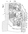
- the clutch 1 shows a first clutch arrangement, consisting of a first clutch 4 and a second clutch 5.
- the clutches 4 and 5 are accommodated in a gear housing 1.
- the first clutch 4 is arranged radially around the second clutch 5.
- the first clutch 4 is composed of a first cylinder 6 with outer plates 7, a second cylinder 8 with inner plates 9, a piston 10 and a return element 12, a plate spring is shown.
- the second clutch 5 consists of a first cylinder 13 with outer plates 14, a second cylinder 15 with inner plates 16, a piston 17, a restoring element 27 and a disk 28.
- the disk 28 is fixed in the axial direction.
- a first shaft 2 drives the first cylinders 6 and 13 of the two clutches 4 and 5.
- the first clutch 4 is driven by a second shaft 3, the second clutch 5 is driven by a third shaft 23.
- the first clutch 4 includes a space 26 and a first compensation space 19.
- the space 26 is formed from the piston 10 and the first cylinder 6.
- the first compensation space 19 is formed from the piston 10 and the first cylinder 13 of the second clutch 5.
- the second clutch 5 includes a space 29 and a second compensation space 20.
- the space 29 is formed from the first cylinder 13 of the second clutch 5 and the piston 17.
- the second compensation space 20 is formed from the piston 17 and the disk 28. If the Space 26 or 29 filled with pressure medium via a feed 11 or 18, the piston 10 or 17 shifts in the axial direction due to the force effect. This closes the clutch 4 or 5.
- the clutches 4 or 5 open when the space 26 or 29 is ventilated. Due to the centrifugal force, a residual volume of the pressure medium remains in the space 26 or 29. This residual volume exerts an axial force on the piston 10 or 17. This axial force is opposite to the direction of force of the restoring element 12 or 27. This delays the deactivation of the first clutch 4 or second clutch 5.
- This disturbance variable is compensated for by setting a corresponding pressure level in the first or second compensation chamber 19 or 20.
- the pressure medium is fed to the two equalizing spaces via the feed 24 or 25.
- the overflow edge 31 determines the pressure level.
- the equalization rooms are supplied with pressure medium via an oil supply system 32, e.g. B. Lubrication system.
- Fig. 1 shows an embodiment in which each of the two compensation spaces 19 and 20 has its own overflow edge 31 and its own opening 22 for oil supply.
- 1 shows a third clutch 35 and a fourth clutch 36.
- the third clutch 35 is arranged radially around the fourth clutch 36.
- the second cylinder 38 of the third clutch 35 is also the first cylinder of the fourth clutch 36.
- the second cylinder 39 of the fourth clutch 36 is connected to the first cylinder 6 of the first clutch 4.
- the first cylinder 37 of the third clutch 35 leads to a shaft, not shown.
- Fig. 2 shows a second embodiment of the clutch arrangement.
- the two compensation spaces 19 and 20 are connected to one another via the inlets 24, 25 and bore 30.
- the overflow edge 31 is jointly formed by the bore 30 for both compensation spaces 19 and 20.
- the pressure medium is fed to the two equalizing spaces 19 and 20 via a feed 21 in the first shaft 2 and an opening 22.
- the piston of the closing clutch pushes the volume of the pressure medium contained therein out of its compensation space into the compensation space of the opening clutch.
- the piston 10 pushes the pressure medium volume of the first compensation space 19 via the feed 24, bore 30 and feed 25 into the second compensation space 20 of the second clutch 5.
- the volume comes from the feed line 21.
- a corresponding pressure level builds up more quickly in the second compensation chamber 20, so that the piston 17 is returned to its starting position more quickly.
- the opening time of the second clutch 5 is reduced. This measure shortens the blocking time for repeated shifts.
- the volume of the pressure medium supplied to the equalization rooms 19 or 20 is not greater than the volume for an individual supply, since the need for the equalization rooms 19 or 20 always occurs at different times.
Claims (5)
- Ensemble d'embrayages avec au moins un premier et au moins un deuxième embrayage (4, 5), chaque embrayage se composant d'un premier cylindre (6, 13) avec des disques externes (7, 14), d'un deuxième cylindre (8, 15) avec des disques internes (9, 16), d'un piston (10, 17) poussant les disques externes contre les disques internes lorsqu'il est activé, d'un élément de rappel (12, 27) ramenant le piston à sa position initiale lorsqu'il n'est pas activé, d'un disque (28) formant ensemble avec le piston une chambre de compensation et s'opposant par l'intermédiaire de la chambre de compensation à une variation de la force de pression du piston en raison d'un mouvement rotatif de l'embrayage, caractérisé en ce que le premier embrayage (4) est disposé radialement autour du deuxième embrayage (5) et en ce que la chambre de compensation (19) du premier embrayage (4) est formée par le piston (10) du premier embrayage (4) et par le premier cylindre (13) du deuxième embrayage (5).
- Ensemble d'embrayages selon la revendication 1, caractérisé en ce que les premiers cylindres (6, 13) du premier et du deuxième embrayage (4, 5) sont entraínés par le même arbre (2).
- Ensemble d'embrayages selon la revendication 1 ou 2, caractérisé en ce qu'un troisième embrayage (35) est disposé radialement autour d'un quatrième embrayage (36), le deuxième cylindre (39) du quatrième embrayage (36) étant relié au premier cylindre (6) du premier embrayage (4) et en ce que le deuxième cylindre (38) du troisième embrayage (35) forme un élément de construction commun avec le premier cylindre du quatrième embrayage (36).
- Ensemble d'embrayages selon la revendication 1, 2 ou 3, caractérisé en ce que la chambre de compensation (19) du premier embrayage (4) et la chambre de compensation (20) du deuxième embrayage (5) communiquent entre elles et sont remplies au moyen d'un orifice commun (22).
- Ensemble d'embrayages selon la revendication 4, caractérisé en ce que les amenées (24, 25) formentt en même temps l'orifice de trop-plein (33), respectivement la rainure de trop-plein (34).
Applications Claiming Priority (3)
| Application Number | Priority Date | Filing Date | Title |
|---|---|---|---|
| DE4415664 | 1994-05-04 | ||
| DE4415664A DE4415664A1 (de) | 1994-05-04 | 1994-05-04 | Kupplungsanordnung |
| PCT/EP1995/001632 WO1995030840A1 (fr) | 1994-05-04 | 1995-04-28 | Systeme d'embrayage |
Publications (2)
| Publication Number | Publication Date |
|---|---|
| EP0758434A1 EP0758434A1 (fr) | 1997-02-19 |
| EP0758434B1 true EP0758434B1 (fr) | 2000-01-05 |
Family
ID=6517236
Family Applications (1)
| Application Number | Title | Priority Date | Filing Date |
|---|---|---|---|
| EP95919362A Expired - Lifetime EP0758434B1 (fr) | 1994-05-04 | 1995-04-28 | Systeme d'embrayage |
Country Status (6)
| Country | Link |
|---|---|
| US (1) | US5887690A (fr) |
| EP (1) | EP0758434B1 (fr) |
| JP (1) | JP3636467B2 (fr) |
| KR (1) | KR100353261B1 (fr) |
| DE (2) | DE4415664A1 (fr) |
| WO (1) | WO1995030840A1 (fr) |
Cited By (7)
| Publication number | Priority date | Publication date | Assignee | Title |
|---|---|---|---|---|
| DE10063781A1 (de) * | 2000-12-21 | 2002-08-14 | Zf Sachs Ag | Kupplungssystem mit einer geberzylinderbetätigten Kupplungseinrichtung |
| EP1339995A1 (fr) * | 2000-12-07 | 2003-09-03 | Mannesmann Sachs Aktiengesellschaft | Systeme d'embrayage a double disque ou a disques multiples et dispositif de disques associe |
| DE102004027088A1 (de) * | 2004-06-02 | 2006-01-05 | Borgwarner Inc., Auburn Hills | Kupplungseinrichtung mit Fliehkraftausgleichseinrichtung sowie Verfahren zum Ausgleichen einer fliehkraftbedingten Druckerhöhung in einem Druckraum für einen Betätigungskolben in einer Kupplungseinrichtung |
| DE102005008971A1 (de) * | 2005-02-28 | 2006-08-31 | Zf Friedrichshafen Ag | Kupplungsanordnung |
| EP1726842A1 (fr) | 2005-05-25 | 2006-11-29 | BorgWarner Inc. | Ensemble embrayage avec embrayages voisins dans le sens radial. |
| DE102007022422A1 (de) | 2007-05-10 | 2008-11-13 | Borgwarner Inc., Auburn Hills | Doppelkupplungsanordnung mit Kolbenführungselement |
| DE10111202B4 (de) * | 2000-12-07 | 2009-06-10 | Zf Sachs Ag | Doppel-oder Mehrfach-Kupplungseinrichtung, und Dichtungskonzept hierfür |
Families Citing this family (72)
| Publication number | Priority date | Publication date | Assignee | Title |
|---|---|---|---|---|
| JPH08219176A (ja) * | 1995-02-08 | 1996-08-27 | Jatco Corp | 多板クラッチのクラッチ組立体構造 |
| DE19921687C5 (de) † | 1999-05-12 | 2016-06-09 | Borgwarner Inc. | Mehrfach-Kupplungssystem für ein Getriebe |
| DE19932614A1 (de) * | 1999-07-13 | 2001-01-18 | Zahnradfabrik Friedrichshafen | Stufenautomatgetriebe |
| DE19932613A1 (de) | 1999-07-13 | 2001-01-18 | Zahnradfabrik Friedrichshafen | Automatgetriebe |
| US6213272B1 (en) * | 1999-08-24 | 2001-04-10 | Borgwarner Inc. | Automatic transmission having nested clutch housings |
| DE10004186B4 (de) * | 1999-09-30 | 2013-03-07 | Volkswagen Ag | Mehrfach-Kupplungseinrichtung |
| DE10034730B4 (de) * | 1999-09-30 | 2010-10-14 | Zf Sachs Ag | Mehrfach-Kupplungseinrichtung, ggf. in Kombination mit einer Torsionsschwingungsdämpferanordnung oder/und einer Elektromaschine |
| DE10004190B4 (de) | 1999-09-30 | 2013-02-07 | Volkswagen Ag | Mehrfach-Kupplungseinrichtung |
| DE10004195B4 (de) * | 1999-09-30 | 2013-02-07 | Volkswagen Ag | Mehrfach-Kupplungseinrichtung |
| FR2799251B1 (fr) | 1999-09-30 | 2006-12-08 | Mannesmann Sachs Ag | Installation d'embrayage multiple de cas echeant en combinaison avec un dispositif amortisseur d'oscillations de torsion ou/et une machine electrique |
| DE10004286B4 (de) | 1999-09-30 | 2010-10-14 | Zf Sachs Ag | Kupplungseinrichtung mit einer hydrodynamischen Kupplung und zumindest zwei Reibungskupplungen |
| DE10004179C5 (de) * | 1999-09-30 | 2017-06-29 | Volkswagen Ag | Mehrfach-Kupplungseinrichtung |
| DE10004189C5 (de) * | 1999-09-30 | 2015-05-21 | Volkswagen Ag | Mehrfach-Kupplungseinrichtung |
| FR2799248B1 (fr) * | 1999-09-30 | 2002-07-12 | Mannesmann Sachs Ag | Installation d'embrayage multiple avec differents rayons de friction |
| SE515482C2 (sv) * | 1999-12-13 | 2001-08-13 | Volvo Lastvagnar Ab | Hydrauliskt manövrerad dubbelkoppling |
| JP2001263369A (ja) * | 2000-03-21 | 2001-09-26 | Aisin Seiki Co Ltd | 自動変速機用クラッチ装置 |
| EP1174632B1 (fr) | 2000-07-17 | 2007-11-28 | ZF Sachs AG | Installation d'embrayage multiple en combinaison avec un dispositif amortisseur d'oscillations de torsion ou/et une machine électrique |
| DE10034677B4 (de) | 2000-07-17 | 2008-04-17 | Zf Sachs Ag | Mehrfachkupplungsanordnung |
| DE10044493B4 (de) * | 2000-09-08 | 2012-05-03 | Zf Sachs Ag | Mehrfach-Kupplungseinrichtung, insbesondere Doppel-Kupplungseinrichtung, für lastschaltbare Getriebe |
| FR2814516B1 (fr) * | 2000-09-22 | 2003-05-02 | Valeo | Dispositif de transmission a engrenages, en particulier pour vehicule automobile |
| DE10049474A1 (de) | 2000-10-06 | 2002-04-25 | Zf Sachs Ag | Kupplungseinrichtung |
| US6382382B1 (en) * | 2000-10-25 | 2002-05-07 | Ford Global Technologies, Inc. | Centrifugally balanced, pressure-operated clutch assembly |
| DE10062600C2 (de) * | 2000-12-12 | 2002-12-05 | Wom World Of Medicine Ag | Peristaltische Schlauchpumpe |
| EP1226992B1 (fr) * | 2001-01-25 | 2004-07-21 | ZF Sachs AG | Dispositif d'accouplement multiple adapté à être monté comme unité de montage préassemblée |
| DE10133638A1 (de) † | 2001-07-11 | 2003-01-30 | Zf Sachs Ag | Mehrfach-Kupplungseinrichtung, insbesondere Doppel-Kupplungseinrichtung |
| JP2004019830A (ja) * | 2002-06-18 | 2004-01-22 | Toyota Motor Corp | 動力伝達断続装置 |
| DE60214995T2 (de) * | 2002-07-18 | 2007-04-26 | Borgwarner Inc., Auburn Hills | Nasskupplung oder Reibscheibebremse |
| DE10248172B4 (de) * | 2002-10-16 | 2013-06-27 | Zf Friedrichshafen Ag | Kupplungsanordnung für ein Getriebe |
| DE10333431A1 (de) * | 2003-07-23 | 2005-02-10 | Zf Friedrichshafen Ag | Kupplungsanordnung in einem Automatgetriebe mit bauraumsparender Kühlmittelversorgung |
| DE602004004223T2 (de) * | 2003-09-30 | 2007-10-25 | Borgwarner Inc., Auburn Hills | Ölverwaltungssytem für Doppelkupplungsantrieb |
| JP2005164028A (ja) * | 2003-10-06 | 2005-06-23 | Borgwarner Inc | パワートレイン変速機用の混合出力システムを備えたマルチクラッチシステム |
| DE50302372D1 (de) * | 2003-10-11 | 2006-04-20 | Borgwarner Inc | Hydraulische Doppelkupplung |
| EP1522752A1 (fr) * | 2003-10-11 | 2005-04-13 | BorgWarner Inc. | Dispositif d'entrainement |
| US7021447B2 (en) * | 2004-04-07 | 2006-04-04 | Freudenberg-Nok General Partnership | Apply piston seal for a clutch |
| US7036645B2 (en) * | 2004-06-18 | 2006-05-02 | General Motors Corporation | Rotating torque-transmitting apparatus |
| DE102004048068B4 (de) | 2004-10-02 | 2014-08-21 | Zf Friedrichshafen Ag | Nasse Lamellenkupplung |
| US7246692B2 (en) * | 2004-10-26 | 2007-07-24 | Borgwarner Inc. | Dual clutch mechanism for a transmission |
| DE102005020415A1 (de) * | 2005-04-27 | 2006-11-09 | Getrag Getriebe- Und Zahnradfabrik Hermann Hagenmeyer Gmbh & Cie Kg | Antriebseinheit für ein Kraftfahrzeug |
| WO2006125046A1 (fr) * | 2005-05-17 | 2006-11-23 | Borgwarner Inc. | Mecanisme de double embrayage pour boite de vitesses |
| JP4720302B2 (ja) * | 2005-06-07 | 2011-07-13 | トヨタ自動車株式会社 | 自動変速機のクラッチ装置 |
| JP4714549B2 (ja) * | 2005-10-11 | 2011-06-29 | いすゞ自動車株式会社 | 複式クラッチ装置 |
| JP4754925B2 (ja) * | 2005-10-11 | 2011-08-24 | 株式会社エクセディ | 複式クラッチ装置 |
| DE102006008243A1 (de) * | 2006-02-22 | 2007-09-06 | Volkswagen Ag | Öldruckversorgung für die Doppelkupplung eines Kraftfahrzeuges bzw. Doppelkupplungsgetriebe mit der zuvor genannten Öldruckversorgung |
| DE102006035649B4 (de) | 2006-07-31 | 2022-03-10 | Zf Friedrichshafen Ag | Kupplungsanordnung für ein Fahrzeug |
| JP5165223B2 (ja) | 2006-09-29 | 2013-03-21 | 本田技研工業株式会社 | 自動二輪車 |
| JP4414996B2 (ja) * | 2006-11-21 | 2010-02-17 | 株式会社エクセディ | 複式クラッチ装置 |
| DE102006059328A1 (de) | 2006-12-16 | 2008-07-24 | Zf Friedrichshafen Ag | Kupplungsanordnung eines Kraftfahrzeug-Antriebsstrangs |
| DE112008000050T5 (de) * | 2007-02-23 | 2009-09-10 | Aisin AW Co., Ltd., Anjo | Automatikgetriebe |
| CN101578461B (zh) * | 2007-02-23 | 2011-11-16 | 爱信艾达株式会社 | 自动变速器 |
| US7802667B2 (en) * | 2007-03-14 | 2010-09-28 | Gm Global Technology Operations, Inc. | Clutch exhaust assembly and method |
| US7854675B2 (en) * | 2007-06-28 | 2010-12-21 | Gm Global Technology Operations, Inc. | Hydraulic feed system for a transmission |
| CN101578464B (zh) * | 2007-07-05 | 2012-11-14 | 爱信艾达株式会社 | 自动变速器 |
| US8221279B2 (en) * | 2008-04-04 | 2012-07-17 | GM Global Technology Operations LLC | Dual apply clutch apparatus for compact electro-mechanical transmission |
| DE102009016282B4 (de) * | 2008-04-04 | 2013-11-21 | GM Global Technology Operations LLC (n. d. Ges. d. Staates Delaware) | Zweifach wirkende Kupplungsvorrichtung für kompaktes elektromechanisches Getriebe |
| DE102008060580B4 (de) * | 2008-06-03 | 2021-01-21 | Borgwarner Inc. | Mehrfach-Kupplungseinrichtung mit zwei Druckausgleichsräumen |
| JP2010048318A (ja) * | 2008-08-21 | 2010-03-04 | Mazda Motor Corp | 自動変速機 |
| JP5062099B2 (ja) * | 2008-08-22 | 2012-10-31 | アイシン・エィ・ダブリュ株式会社 | 自動変速機 |
| JP5152333B2 (ja) | 2008-08-22 | 2013-02-27 | アイシン・エィ・ダブリュ株式会社 | 自動変速機 |
| US8453819B2 (en) * | 2010-02-22 | 2013-06-04 | Twin Disc, Inc. | Balanced clutch system |
| JP5497508B2 (ja) * | 2010-03-26 | 2014-05-21 | 本田技研工業株式会社 | エンジンの油圧クラッチ用油路構造 |
| DE102011004467A1 (de) * | 2011-02-21 | 2012-08-23 | Zf Friedrichshafen Ag | Verfahren und Vorrichtung zur Ansteuerung von Schaltelementen eines automatischen Getriebes mit Start-Stopp-Automatik |
| US8844695B2 (en) * | 2011-02-24 | 2014-09-30 | Ford Global Technologies, Llc | Carrying fluid to balance dams in a servo piston support |
| DE102012201509A1 (de) * | 2012-02-02 | 2013-08-08 | Zf Friedrichshafen Ag | Kupplungsanordnung und Dichtelement |
| US8613682B2 (en) * | 2012-05-04 | 2013-12-24 | GM Global Technology Operations LLC | Rotating clutch balance fill system |
| US9222526B2 (en) * | 2012-10-23 | 2015-12-29 | Ford Global Technologies, Llc | Clutch housing and assembly |
| US9945428B2 (en) * | 2012-10-23 | 2018-04-17 | Ford Global Technologies, Llc | Clutch assembly and transmission |
| JP6052401B2 (ja) | 2013-04-30 | 2016-12-27 | アイシン・エィ・ダブリュ株式会社 | 変速装置 |
| JP6110249B2 (ja) * | 2013-08-02 | 2017-04-05 | 株式会社ダイナックス | 油圧式クラッチ |
| JP6496625B2 (ja) * | 2015-07-17 | 2019-04-03 | ジヤトコ株式会社 | 湿式クラッチ装置 |
| DE102015215895A1 (de) * | 2015-08-20 | 2017-02-23 | Schaeffler Technologies AG & Co. KG | Kupplungseinrichtung für Hybridantrieb |
| DE102018201781A1 (de) * | 2018-02-06 | 2019-08-08 | Zf Friedrichshafen Ag | Kupplungsvorrichtung |
| US10895289B2 (en) * | 2019-05-07 | 2021-01-19 | Allison Transmission, Inc. | Clutch assemblies with balance cavities formed by disc springs |
Family Cites Families (7)
| Publication number | Priority date | Publication date | Assignee | Title |
|---|---|---|---|---|
| US4010833A (en) * | 1975-02-19 | 1977-03-08 | Zahnradfabrik Friedrichshafen Ag | Clutch assembly for planetary-gear trains |
| JPS5937338A (ja) * | 1982-08-23 | 1984-02-29 | Nissan Motor Co Ltd | 多板クラツチ装置のクラツチドラム |
| JPH0781594B2 (ja) * | 1985-08-31 | 1995-08-30 | 三菱自動車工業株式会社 | 動力伝達装置 |
| DE3611003C1 (de) * | 1986-04-02 | 1987-10-08 | Daimler Benz Ag | Druckmittel-Stellglied zur Betaetigung einer Lamellen-Kupplung mit einem Schmierventil |
| JP2957184B2 (ja) * | 1988-09-27 | 1999-10-04 | アイシン・エィ・ダブリュ株式会社 | 自動変速機における油圧装置 |
| GB2264152B (en) * | 1992-01-30 | 1995-04-26 | Nissan Motor | Automatic transmission |
| JP3354303B2 (ja) * | 1994-08-19 | 2002-12-09 | 本田技研工業株式会社 | タンデム型油圧クラッチ |
-
1994
- 1994-05-04 DE DE4415664A patent/DE4415664A1/de not_active Withdrawn
-
1995
- 1995-04-28 WO PCT/EP1995/001632 patent/WO1995030840A1/fr active IP Right Grant
- 1995-04-28 JP JP52865595A patent/JP3636467B2/ja not_active Expired - Lifetime
- 1995-04-28 KR KR1019960706123A patent/KR100353261B1/ko not_active IP Right Cessation
- 1995-04-28 DE DE59507579T patent/DE59507579D1/de not_active Expired - Lifetime
- 1995-04-28 US US08/732,428 patent/US5887690A/en not_active Expired - Lifetime
- 1995-04-28 EP EP95919362A patent/EP0758434B1/fr not_active Expired - Lifetime
Cited By (12)
| Publication number | Priority date | Publication date | Assignee | Title |
|---|---|---|---|---|
| EP1339995A1 (fr) * | 2000-12-07 | 2003-09-03 | Mannesmann Sachs Aktiengesellschaft | Systeme d'embrayage a double disque ou a disques multiples et dispositif de disques associe |
| US7114605B2 (en) | 2000-12-07 | 2006-10-03 | Zf Sachs Ag | Double or multiple disk coupling device and disk arrangement therefor |
| DE10111202B4 (de) * | 2000-12-07 | 2009-06-10 | Zf Sachs Ag | Doppel-oder Mehrfach-Kupplungseinrichtung, und Dichtungskonzept hierfür |
| EP1339995B1 (fr) * | 2000-12-07 | 2014-01-08 | ZF Friedrichshafen AG | Systeme d'embrayage a double disque ou a disques multiples et dispositif de disques associe |
| DE10063781A1 (de) * | 2000-12-21 | 2002-08-14 | Zf Sachs Ag | Kupplungssystem mit einer geberzylinderbetätigten Kupplungseinrichtung |
| DE10063781C2 (de) * | 2000-12-21 | 2003-02-20 | Zf Sachs Ag | Kupplungssystem mit einer geberzylinderbetätigten Kupplungseinrichtung |
| DE102004027088A1 (de) * | 2004-06-02 | 2006-01-05 | Borgwarner Inc., Auburn Hills | Kupplungseinrichtung mit Fliehkraftausgleichseinrichtung sowie Verfahren zum Ausgleichen einer fliehkraftbedingten Druckerhöhung in einem Druckraum für einen Betätigungskolben in einer Kupplungseinrichtung |
| DE102004027088B4 (de) * | 2004-06-02 | 2009-02-05 | Borgwarner Inc., Auburn Hills | Kupplungseinrichtung mit Fliehkraftausgleichseinrichtung sowie Verfahren zum Ausgleichen einer fliehkraftbedingten Druckerhöhung in einem Druckraum für einen Betätigungskolben in einer Kupplungseinrichtung |
| DE102005008971A1 (de) * | 2005-02-28 | 2006-08-31 | Zf Friedrichshafen Ag | Kupplungsanordnung |
| EP1726842A1 (fr) | 2005-05-25 | 2006-11-29 | BorgWarner Inc. | Ensemble embrayage avec embrayages voisins dans le sens radial. |
| DE102007022422A1 (de) | 2007-05-10 | 2008-11-13 | Borgwarner Inc., Auburn Hills | Doppelkupplungsanordnung mit Kolbenführungselement |
| WO2008138460A1 (fr) | 2007-05-10 | 2008-11-20 | Borgwarner Inc. | Dispositif d'embrayage double avec élément de guidage de piston |
Also Published As
| Publication number | Publication date |
|---|---|
| KR970702968A (ko) | 1997-06-10 |
| EP0758434A1 (fr) | 1997-02-19 |
| DE59507579D1 (de) | 2000-02-10 |
| JP3636467B2 (ja) | 2005-04-06 |
| WO1995030840A1 (fr) | 1995-11-16 |
| DE4415664A1 (de) | 1995-11-09 |
| JPH09512888A (ja) | 1997-12-22 |
| KR100353261B1 (ko) | 2003-09-19 |
| US5887690A (en) | 1999-03-30 |
Similar Documents
| Publication | Publication Date | Title |
|---|---|---|
| EP0758434B1 (fr) | Systeme d'embrayage | |
| DE4302773C2 (de) | Naß-Reibteil | |
| DE3432403C2 (de) | Lamellenkupplung | |
| EP1097311B1 (fr) | Embrayage a disques dans une transmission a couple differencie | |
| DE4206100B4 (de) | Schaltbares Planetengetriebe | |
| DE2619011C3 (de) | Planetenwechselgetriebe für Fahrzeuge | |
| DE102006046282B4 (de) | Radial geschichtete Doppeltrockenkupplungsanordnung | |
| DE10323514A1 (de) | Kupplungsvorrichtung, insbesondere Lamellenkupplung für ein Doppelkupplungsgetriebe | |
| AT8987U1 (de) | Hydrauliksystem für die steuerung zweier aktuatoren und getriebe mit einem solchen | |
| DE102015217164A1 (de) | Baugruppe mit einer Reibeinrichtung | |
| DE102005045322A1 (de) | Doppelscheibenfeder | |
| DE102005031149B4 (de) | Getriebeanordnung mit Reibplatten | |
| DE19604248A1 (de) | Kupplungseinrichtung für Mehrscheibenkupplung | |
| WO1988007144A1 (fr) | Frein ou embrayage a disque de friction a circuit pressurise | |
| DE4239610C2 (de) | Dämpfungsscheibenausbildung | |
| DE10207668A1 (de) | Mehrscheibenkupplungsvorrichtung | |
| DE10131816A1 (de) | Schaltelement-Baugruppe für ein Getriebe | |
| DE3444103A1 (de) | Druckmittelbetaetigbare schaltkupplung | |
| WO1999054637A1 (fr) | Actionneur pour le systeme de freinage d'un vehicule automobile | |
| DE102004058871B4 (de) | Doppelkupplung | |
| EP1048868B1 (fr) | Embrayage à commande hydraulique | |
| DE102004058872B4 (de) | Doppelkupplung | |
| DE102008057657A1 (de) | Kraftübertragungsvorrichtung | |
| DE3309104A1 (de) | Lamellenkupplung | |
| DE19508855C2 (de) | Hydrodynamischer Drehmomentwandler mit einer Überbrückungskupplung |
Legal Events
| Date | Code | Title | Description |
|---|---|---|---|
| PUAI | Public reference made under article 153(3) epc to a published international application that has entered the european phase |
Free format text: ORIGINAL CODE: 0009012 |
|
| 17P | Request for examination filed |
Effective date: 19961204 |
|
| AK | Designated contracting states |
Kind code of ref document: A1 Designated state(s): DE FR GB IT SE |
|
| GRAG | Despatch of communication of intention to grant |
Free format text: ORIGINAL CODE: EPIDOS AGRA |
|
| GRAG | Despatch of communication of intention to grant |
Free format text: ORIGINAL CODE: EPIDOS AGRA |
|
| GRAH | Despatch of communication of intention to grant a patent |
Free format text: ORIGINAL CODE: EPIDOS IGRA |
|
| 17Q | First examination report despatched |
Effective date: 19990618 |
|
| ITF | It: translation for a ep patent filed |
Owner name: DE DOMINICIS & MAYER S.R.L. |
|
| GRAH | Despatch of communication of intention to grant a patent |
Free format text: ORIGINAL CODE: EPIDOS IGRA |
|
| GRAA | (expected) grant |
Free format text: ORIGINAL CODE: 0009210 |
|
| AK | Designated contracting states |
Kind code of ref document: B1 Designated state(s): DE FR GB IT SE |
|
| GBT | Gb: translation of ep patent filed (gb section 77(6)(a)/1977) |
Effective date: 20000106 |
|
| REF | Corresponds to: |
Ref document number: 59507579 Country of ref document: DE Date of ref document: 20000210 |
|
| ET | Fr: translation filed | ||
| PLBQ | Unpublished change to opponent data |
Free format text: ORIGINAL CODE: EPIDOS OPPO |
|
| PLBI | Opposition filed |
Free format text: ORIGINAL CODE: 0009260 |
|
| PLBF | Reply of patent proprietor to notice(s) of opposition |
Free format text: ORIGINAL CODE: EPIDOS OBSO |
|
| 26 | Opposition filed |
Opponent name: MANNESMANN SACHS AG Effective date: 20001005 |
|
| PLBF | Reply of patent proprietor to notice(s) of opposition |
Free format text: ORIGINAL CODE: EPIDOS OBSO |
|
| PLBL | Opposition procedure terminated |
Free format text: ORIGINAL CODE: EPIDOS OPPC |
|
| REG | Reference to a national code |
Ref country code: GB Ref legal event code: IF02 |
|
| PLBM | Termination of opposition procedure: date of legal effect published |
Free format text: ORIGINAL CODE: 0009276 |
|
| STAA | Information on the status of an ep patent application or granted ep patent |
Free format text: STATUS: OPPOSITION PROCEDURE CLOSED |
|
| 27C | Opposition proceedings terminated |
Effective date: 20020107 |
|
| PGFP | Annual fee paid to national office [announced via postgrant information from national office to epo] |
Ref country code: SE Payment date: 20080408 Year of fee payment: 14 |
|
| PGFP | Annual fee paid to national office [announced via postgrant information from national office to epo] |
Ref country code: IT Payment date: 20090423 Year of fee payment: 15 |
|
| PGFP | Annual fee paid to national office [announced via postgrant information from national office to epo] |
Ref country code: GB Payment date: 20090422 Year of fee payment: 15 |
|
| EUG | Se: european patent has lapsed | ||
| GBPC | Gb: european patent ceased through non-payment of renewal fee |
Effective date: 20100428 |
|
| PG25 | Lapsed in a contracting state [announced via postgrant information from national office to epo] |
Ref country code: GB Free format text: LAPSE BECAUSE OF NON-PAYMENT OF DUE FEES Effective date: 20100428 Ref country code: IT Free format text: LAPSE BECAUSE OF NON-PAYMENT OF DUE FEES Effective date: 20100428 |
|
| PG25 | Lapsed in a contracting state [announced via postgrant information from national office to epo] |
Ref country code: SE Free format text: LAPSE BECAUSE OF NON-PAYMENT OF DUE FEES Effective date: 20090429 |
|
| PGFP | Annual fee paid to national office [announced via postgrant information from national office to epo] |
Ref country code: FR Payment date: 20120504 Year of fee payment: 18 |
|
| REG | Reference to a national code |
Ref country code: FR Ref legal event code: ST Effective date: 20131231 |
|
| PG25 | Lapsed in a contracting state [announced via postgrant information from national office to epo] |
Ref country code: FR Free format text: LAPSE BECAUSE OF NON-PAYMENT OF DUE FEES Effective date: 20130430 |
|
| PGFP | Annual fee paid to national office [announced via postgrant information from national office to epo] |
Ref country code: DE Payment date: 20140430 Year of fee payment: 20 |
|
| REG | Reference to a national code |
Ref country code: DE Ref legal event code: R071 Ref document number: 59507579 Country of ref document: DE |