EP0757756B1 - Dickstoffpumpe - Google Patents
Dickstoffpumpe Download PDFInfo
- Publication number
- EP0757756B1 EP0757756B1 EP95917350A EP95917350A EP0757756B1 EP 0757756 B1 EP0757756 B1 EP 0757756B1 EP 95917350 A EP95917350 A EP 95917350A EP 95917350 A EP95917350 A EP 95917350A EP 0757756 B1 EP0757756 B1 EP 0757756B1
- Authority
- EP
- European Patent Office
- Prior art keywords
- pipe
- cleaning
- conveyor
- thick matter
- material feed
- Prior art date
- Legal status (The legal status is an assumption and is not a legal conclusion. Google has not performed a legal analysis and makes no representation as to the accuracy of the status listed.)
- Expired - Lifetime
Links
- 238000004140 cleaning Methods 0.000 claims description 80
- 239000000463 material Substances 0.000 claims description 45
- XLYOFNOQVPJJNP-UHFFFAOYSA-N water Substances O XLYOFNOQVPJJNP-UHFFFAOYSA-N 0.000 claims description 11
- 238000007789 sealing Methods 0.000 claims description 8
- 239000007788 liquid Substances 0.000 claims description 4
- 230000000903 blocking effect Effects 0.000 claims 9
- 238000000034 method Methods 0.000 description 7
- 230000008878 coupling Effects 0.000 description 2
- 238000010168 coupling process Methods 0.000 description 2
- 238000005859 coupling reaction Methods 0.000 description 2
- 238000011161 development Methods 0.000 description 2
- 230000018109 developmental process Effects 0.000 description 2
- 238000010586 diagram Methods 0.000 description 2
- 239000000314 lubricant Substances 0.000 description 2
- 238000005086 pumping Methods 0.000 description 2
- 241000282887 Suidae Species 0.000 description 1
- 230000001419 dependent effect Effects 0.000 description 1
- 239000012530 fluid Substances 0.000 description 1
- 239000002002 slurry Substances 0.000 description 1
Images



Classifications
-
- F—MECHANICAL ENGINEERING; LIGHTING; HEATING; WEAPONS; BLASTING
- F04—POSITIVE - DISPLACEMENT MACHINES FOR LIQUIDS; PUMPS FOR LIQUIDS OR ELASTIC FLUIDS
- F04B—POSITIVE-DISPLACEMENT MACHINES FOR LIQUIDS; PUMPS
- F04B15/00—Pumps adapted to handle specific fluids, e.g. by selection of specific materials for pumps or pump parts
- F04B15/02—Pumps adapted to handle specific fluids, e.g. by selection of specific materials for pumps or pump parts the fluids being viscous or non-homogeneous
- F04B15/023—Pumps adapted to handle specific fluids, e.g. by selection of specific materials for pumps or pump parts the fluids being viscous or non-homogeneous supply of fluid to the pump by gravity through a hopper, e.g. without intake valve
-
- B—PERFORMING OPERATIONS; TRANSPORTING
- B08—CLEANING
- B08B—CLEANING IN GENERAL; PREVENTION OF FOULING IN GENERAL
- B08B9/00—Cleaning hollow articles by methods or apparatus specially adapted thereto
- B08B9/02—Cleaning pipes or tubes or systems of pipes or tubes
- B08B9/027—Cleaning the internal surfaces; Removal of blockages
- B08B9/04—Cleaning the internal surfaces; Removal of blockages using cleaning devices introduced into and moved along the pipes
- B08B9/053—Cleaning the internal surfaces; Removal of blockages using cleaning devices introduced into and moved along the pipes moved along the pipes by a fluid, e.g. by fluid pressure or by suction
-
- B—PERFORMING OPERATIONS; TRANSPORTING
- B08—CLEANING
- B08B—CLEANING IN GENERAL; PREVENTION OF FOULING IN GENERAL
- B08B9/00—Cleaning hollow articles by methods or apparatus specially adapted thereto
- B08B9/02—Cleaning pipes or tubes or systems of pipes or tubes
- B08B9/027—Cleaning the internal surfaces; Removal of blockages
- B08B9/04—Cleaning the internal surfaces; Removal of blockages using cleaning devices introduced into and moved along the pipes
- B08B9/053—Cleaning the internal surfaces; Removal of blockages using cleaning devices introduced into and moved along the pipes moved along the pipes by a fluid, e.g. by fluid pressure or by suction
- B08B9/055—Cleaning the internal surfaces; Removal of blockages using cleaning devices introduced into and moved along the pipes moved along the pipes by a fluid, e.g. by fluid pressure or by suction the cleaning devices conforming to, or being conformable to, substantially the same cross-section of the pipes, e.g. pigs or moles
-
- F—MECHANICAL ENGINEERING; LIGHTING; HEATING; WEAPONS; BLASTING
- F04—POSITIVE - DISPLACEMENT MACHINES FOR LIQUIDS; PUMPS FOR LIQUIDS OR ELASTIC FLUIDS
- F04B—POSITIVE-DISPLACEMENT MACHINES FOR LIQUIDS; PUMPS
- F04B7/00—Piston machines or pumps characterised by having positively-driven valving
- F04B7/02—Piston machines or pumps characterised by having positively-driven valving the valving being fluid-actuated
- F04B7/0233—Piston machines or pumps characterised by having positively-driven valving the valving being fluid-actuated a common distribution member forming a single discharge distributor for a plurality of pumping chambers
- F04B7/0258—Piston machines or pumps characterised by having positively-driven valving the valving being fluid-actuated a common distribution member forming a single discharge distributor for a plurality of pumping chambers and having an orbital movement, e.g. elbow-pipe type members
Definitions
- the invention relates to a thick matter pump with a material feed container, two with theirs end openings in the interior of the material feed container opening, hydraulically driven delivery cylinders , one in the material feed container engaging, alternating with one end in cycles with the front openings of the feed cylinders communicating and with its other end at one Conveyor tube connected swivel tube and with an in close to the end of the delivery pipe on the swivel tube side or in an outside of the material feed container arranged section of the swivel tube in the relevant Pipe wall arranged closable cleaning opening.
- Thick matter pumps of this type are primarily used for pumping of concrete and more or less viscous Sludges are used, which solidify after long periods of inactivity can. Therefore the pipelines of the Thick matter pump and the material feed container at the end of a conveying process can be emptied and cleaned.
- the Delivery line which is usually on a placing boom in concrete pumps attached, either by sucking it back of the concrete contained in it in the material feed container through the thick matter pump itself or under pressure in the reverse direction with the help of an in the delivery line injected pressure medium, such as compressed air or water.
- Wiping the Pipelines are made using elastomeric sponge balls or cleaning body, either over the free end of the conveyor pipe sucked to the material feed container or via suitable pipe fittings (EP-A-22 251) in the opposite direction. Further it is known (EP-A-171 796), in the region of the swivel tube lockable cleaning openings in the pipeline wall to be provided through for cleaning purposes access to the inside of the pipeline is possible is. This has not yet been satisfactorily resolved Problem of emptying using the in the material feed container remaining concrete. Also the Handling the sponge balls in the course of cleaning the Pipelines have so far left something to be desired.
- the invention is based on the object the known concrete pumps of the initially mentioned kind of improving that the conveyor pipe can be emptied and cleaned in a few simple steps can.
- the invention proposes in the pipe wall of the conveyor pipe and / or the swivel tube already existing cleaning openings in addition to introducing sponge balls on the one hand and / or for emptying the material feed container to use on the other hand and to those in the pipe wall the delivery pipe and / or the swivel pipe lockable cleaning opening one-sided open to the cleaning opening, at least one Cleaning cartridge with compressed air and / or pressurized water connection connect, with the conveyor pipe and / or the swivel tube on the delivery cylinder side by means of a Shut-off device is closable.
- the cleaning cartridge is advantageously by means of a locking member, in particular a gate valve lockable towards the cleaning opening.
- a locking member in particular a gate valve lockable towards the cleaning opening.
- the cleaning cartridge in the area of the cleaning opening articulated on the conveyor tube or swivel tube so that it from the cleaning opening, preferably when it is closed Gate valve releasing their front Opening is pivotable.
- the same result can be achieved in that the cleaning cartridge and the gate valve rigidly connected to each other and optional are movable against the cleaning opening.
- the cleaning slide can also be used for two cleaning cartridges be connected, optionally with sponge balls, Cleaning pigs or filled with liquid-filled bags can be.
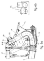
- a transport pipe can also be attached to the cleaning opening connected via which the material feed container with the help of the delivery cylinder except for one small remaining amount can be emptied.
- a conveyor tube or swivel tube Shut-off device closing towards the free end of the conveyor pipe intended.
- the invention proposed that the in Material feed container opening front cylinder openings at least partially against air ingress from the material feed container to the vicinity of the container base preferably covered by a slider or are lockable.
- the shut-off device can be used, for example, as a gate valve be formed, which is useful in the area of a Conveyor pipe-side connection flange outside the material feed container is arranged.
- the shut-off device can also be used as a Pipe inside against the conveyor pipe or swivel pipe wall compressible, preferably deformable under pressure Be formed sealing body of the Cleaning cartridge from in the conveyor or swivel tube insertable and in this preferably by means of a limp, band or chain-like holding member is positionable.
- a sealing body not unintentionally from the conveyor pipe or the Swivel tube is pushed out, regardless of the holding element or in addition to it into the inside of the pipe, preferably engaging from the cleaning opening Seat or support element for the sealing body be provided.
- a preferred embodiment of the Invention provides that the sealing body as under the Exposure to a pressure medium, preferably compressed air or hydraulic fluid spreadable, and against the inner surface of the tube or ball can be pressed is.
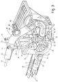
- the two-cylinder slurry pumps shown in the drawing are for use in stationary and mobile concrete pumps determined. They essentially exist from two delivery cylinders 10 with hydraulic in Push-pull driven delivery piston 12, a material feed container 14 and one with a swivel tube 16 engaging in the material feed container 14, with a reversing mechanism 18 actuable slide device 20.
- the feed cylinder 10 are in the lower area via openings 22 to the rear wall 24 of the material feed container 14 connected, the openings 22 on the inside of the material feed container 14 through an eyeglass-shaped wear plate 26 are limited.
- the swivel tube 16 lies with its one a wear ring 28 bearing end against the Wear plate 26 and is by the reversing mechanism 18 depending on the direction of movement the delivery piston 12 in the delivery cylinders 10 in front of the one or the other opening 22 is pivoted. In this way is when the delivery piston is moved back in the direction of arrow 30 12 Material from the material feed container 14 through the opening 22 in the direction of arrow 32 in the relevant feed cylinder 10 sucked in while over the other delivery piston 12 material in the direction arrows 34, 36, 38 through the swivel tube 16 into an outside of the material feed container 14 Delivery pipe 42 is transported.
- the conveyor pipe 42 can on a delivery line, not shown of a concrete placing boom.
- FIGS. 1 and 3 differ mainly in the shape of the swivel tube 16.
- this is Swivel tube is essentially S-shaped. It is on its opposite the delivery cylinders End over a container-fixed, to its swivel axis coaxial rotary pipe connection 43 with the delivery pipe 42 connected, and engages on the other side with one designed as a drive shaft axle shaft 45 by a Pivot bearing 47 of the material feed container 14 therethrough.
- the stub of the axle shaft projecting outwards 45 is rotationally fixed with a reversing lever 46 of the reversing mechanism 18 connected up at his facing end two facing opposite sides, bearings 48 designed as ball sockets for the connection of a piston-side ball head 50 of the two drive cylinders 52 of the reversing mechanism 18 has.
- the drive cylinders are on the cylinder side 52 with a further ball head 54 in one Supporting cylinder-fixed bearing designed as a ball socket 56 stored.
- a C-shaped pivot tube 16 that from above into the material feed container 14 engages.
- the swivel tube 16 is over a Flange 40 with the extension tube Conveyor tube 42 connected, which in turn via a Pipe rotary connection, not shown, to a delivery line a concrete placing boom is connected.
- the flange 40 is connected by means of two clamping screws 44 the reversing lever 46 of the reversing mechanism 18 releasably connected, the opposite at its lower end two Side-facing ball pans Bearings 48 for the connection of a piston side Ball head 50 of the two drive cylinders 52 of the reversing mechanism 18.
- On the cylinder side are the drive cylinders 52 with another Ball head 54 in a conveyor cylinder fixed, as Ball socket trained bearing 56 stored.
- the Drive cylinders 52 can be pressurized with pressure oil on one side and contain a ball head 50 Plunger 60.
- the pipelines the thick matter pump and the material feed container are emptied and be cleaned.
- the pipelines the thick matter pump and the material feed container are emptied and be cleaned.
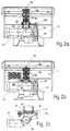
- cleaning openings 80 are provided, the one with a cover 82 and a coupling member 84 are closable.
- the cleaning ports 80 optionally one essentially cylindrical cleaning cartridge 86 connected with cleaning bodies 88,88 'or with liquid bags 88 '' equipped and via the connections 90, 92 with pressurized water or compressed air can.
- a shut-off device is provided on the side of the delivery cylinder, that in the case of FIGS. 2a, b and c and 4a as Gate valve 94.96 and in the case of FIG. 5 as at the Inner surface of the swivel tube 16 compressible inflatable Balloon 98 is formed.
- the locking slide 94 according to FIGS. 2a to c is located in the area of the pipe joint 43, and is in there Direction of the double arrow 100 is vertically displaceable arranged.
- the cleaning opening 80 for the connection the cleaning cartridge 86 is in this case on a conveyor tube piece designed as a folding tube 42, which after loosening the quick-release fastener 102 Joint 104 for cleaning purposes with the release of Pipe rotary connection 43 is pivotable.
- the cleaning cartridge 86 demonstrates in the exemplary embodiment Fig. 2a on a gate valve 106, which during the Conveying process is closed and during the cleaning process can be brought into its open position.
- the cleaning cartridge 86 the joint 108 can be pivoted relative to the cleaning opening 80, after previously removing the coupling member 84 has been. This way, with a few Handles the opening of the cleaning cartridge 86 to Filling with the cleaning bodies 88 released.
- Fig. 4a to c is one of two cleaning cartridges 86 and a slide plate 110 existing cartridge valve 112 provided, the to the cleaning opening 80 of the conveyor pipe 42nd is flanged. By moving the cleaning cartridges to the side 86 beyond the base plate 112 the cleaning body 88, 88 ', 88 "from below in the cleaning cartridges 86 are inserted.
- the gate valve is activated first 96 closed in the conveyor tube 42. Then one of the Cleaning cartridges 86 through the cleaning opening 80 pushed and briefly exposed to water at connection 90, so that two of the three cleaning bodies 88 in the pipeline is pressed in. Then will the water connection is closed and the third cleaning body 88 with compressed air via port 92 in the Delivery line pressed. At the end of the delivery line mounted a discharge stand, not shown, so that the Concrete and the cleaning elements can be safely removed from the delivery line can exit.
- the cleaning cartridges 86 can also be used as a pumping aid by one filled with a lubricant or lubricant Bag 88 '' inserted with water into the delivery line pressed and then with the concrete to the exit of the Delivery line is pumped.
- the bag opens 88 '' and distributes its contents on the inner surface the delivery line.
- the cleaning body for wiping the conveyor line again End of the delivery line through the switch to suction mode Feed pump 10, 12 with shut-off element 94 open, 96.98 conveyed back into the material feed container 14 become. In this way, this also becomes the material feed container leading last conveyor pipe section 42 velvet Swivel tube 16 cleaned.
- the invention refers to a thick matter pump, in particular a concrete pump with a material feed container 14, two with their end openings 22 into the interior of the material feed container 14 opening conveying cylinders 10, which engages in the material feed container 14, with one end alternating in cycles with the front openings 22 of the feed cylinder communicating and with its other end at one Conveyor tube 42 connected swivel tube 16 and with one near the swivel tube end of the Conveyor tube 42 or in an outside of the material feed container arranged section of the swivel tube 16 arranged closable in the relevant pipe wall Cleaning opening 80.
- a cleaning cartridge 86 to the cleaning opening 80 connectable, the a compressed air and / or pressurized water connection 90.92, while the conveyor pipe 42nd and / or the swivel tube 16 on the delivery cylinder side by means of a shut-off device 94, 96, 98 can be closed.
Landscapes
- Engineering & Computer Science (AREA)
- Mechanical Engineering (AREA)
- Physics & Mathematics (AREA)
- Fluid Mechanics (AREA)
- General Engineering & Computer Science (AREA)
- Reciprocating Pumps (AREA)
- On-Site Construction Work That Accompanies The Preparation And Application Of Concrete (AREA)
Description
- Fig. 1
- eine schaubildliche Darstellung einer Dickstoffpumpe mit S-förmigem Schwenkrohr;
- Fig. 2a bis c
- zwei Ausführungsvarianten einer Dickstoffpumpe entsprechend Fig. 1 mit Reinigungspatrone in einer Rückseitenansicht und einer ausschnittsweisen Draufsicht;
- Fig. 3
- eine schaubildliche Darstellung einer Dickstoffpumpe mit C-förmigem Schwenkrohr;
- Fig. 4a
- eine Seitenansicht der Dickstoffpumpe nach Fig. 3 in teilweise geschnittener Darstellung;
- Fig. 4b und c
- einen Schnitt durch die Reinigungspatrone entlang der Schnittlinie A-A der Fig. 4a mit unterschiedlicher Füllung;
- Fig. 5
- eine Darstellung entsprechend Fig. 4a mit an einer Reinigungsöffnung des Schwenkrohrs angeflanschter Reinigungspatrone;
- Fig. 6a
- eine Darstellung entsprechend Fig. 5 mit am Schwenkrohr angeflanschtem Transportrohr und mit förderzylinderseitigen Begrenzungsschiebern;
- Fig. 6b
- eine Stirnseitenansicht der Begrenzungsschieber nach Fig. 6a.
Claims (12)
- Dickstoffpumpe mit einem Materialaufgabebehälter (14), zwei mit ihren stirnseitigen Öffnungen (22) in das Innere des Materialaufgabebehälters (14) mündenden, hydraulisch angetriebenen Förderzylindern (10), einem in den Materialaufgabebehälter (14) eingreifenden, mit seinem einen Ende taktweise abwechselnd mit den stirnseitigen Öffnungen (22) der Förderzylinder (10) kommunizierenden und mit seinem anderen Ende an ein Förderrohr (42) angeschlossenen Schwenkrohr (16) und mit einer in der Nähe des schwenkrohrseitigen Endes des Förderrohrs (42) oder in einem außerhalb des Materialaufgabebehälters (14) angeordneten Abschnitt des Schwenkrohrs (16) in der betreffenden Rohrwand angeordneten verschließbaren Reinigungsöffnung (80), dadurch gekennzeichnet, daß an die Rohrwand von außen her eine einseitig zur Reinigungsöffnung (80) hin offene, mindestens einen Preßluft- und/ oder Druckwasseranschluß (90,92) aufweisende Reinigungspatrone (86) anschließbar ist und daß das Förderrohr (42) und/ oder das Schwenkrohr (16) förderzylinderseitig mittels eines Absperrorgans (94,96,98) verschließbar ist.
- Dickstoffpumpe nach Anspruch 1, dadurch gekennzeichnet, daß die Reinigungspatrone (86) mittels eines Sperrorgans, insbesondere eines Sperrschiebers (106,110) zur Reinigungsöffnung (80) hin absperrbar ist.
- Dickstoffpumpe nach Anspruch 1 oder 2, dadurch gekennzeichnet, daß die Reinigungspatrone (86) im Bereich der Reinigungsöffnung (80) am Förderrohr (42) oder am Schwenkrohr (16) so angelenkt ist, daß sie von der Reinigungsöffnung (80) unter Freigabe ihrer stirnseitigen Öffnung wegschwenkbar ist.
- Dickstoffpumpe nach Anspruch 2, dadurch gekennzeichnet, daß mindestens eine Reinigungspatrone (86) und der Sperrschieber (106) starr miteinander verbunden und wahlweise gegen die Reinigungsöffnung (80) verschiebbar sind.
- Dickstoffpumpe nach einem der Ansprüche 1 bis 4, dadurch gekennzeichnet, daß an die Rohrwand von außen her ein zur Reinigungsöffnung (80) offenes Transportrohr (122) anschließbar ist und daß das Förderrohr (42) oder das Schwenkrohr (16) zum freien Förderrohrende hin mittels eines Absperrorgans (98) verschließbar ist.
- Dickstoffpumpe nach Anspruch 5, dadurch gekennzeichnet, daß die in den Materialaufgabebehälter (14) mündenden stirnseitigen Förderzylinderöffnungen (22) gegen Luftzutritt aus dem Materialaufgabebehälter (14) zumindest teilweise bis in die Nähe des Materialaufgabebehälterbodens, vorzugsweise mittels eines Schiebers (124) abdeckbar oder verschließbar sind.
- Dickstoffpumpe nach einem der Ansprüche 1 bis 6, dadurch gekennzeichnet, daß das Absperrorgan als Absperrschieber (94,96) ausgebildet ist.
- Dickstoffpumpe nach Anspruch 7, dadurch gekennzeichnet, daß der Absperrschieber (96) im Bereich eines förderrohrseitigen Anschlußflanschs (40) außerhalb des Materialaufgabebehälters (14) angeordnet ist.
- Dickstoffpumpe nach einem der Ansprüche 1 bis 6, dadurch gekennzeichnet, daß das Absperrorgan als im Rohrinneren gegen die Förderrohr- oder Schwenkrohrwand anpreßbarer, vorzugsweise unter Druckeinwirkung verformbarer Dichtkörper (98) ausgebildet ist.
- Dickstoffpumpe nach Anspruch 9, dadurch gekennzeichnet, daß der Dichtkörper (98) von der Reinigungspatrone aus in das Förder- oder Schwenkrohr einführbar und in diesem vorzugsweise mittels eines biegeschlaffen, band- oder kettenartigen Halteorgans (116) positionierbar ist.
- Dickstoffpumpe nach Anspruch 9 oder 10, dadurch gekennzeichnet, daß der Dichtkörper (98) als unter der Einwirkung eines Druckmediums, vorzugsweise von Druckluft oder Druckflüssigkeit aufspreizbarer, gegen die Rohrinnenfläche anpreßbarer Ballon oder Ball ausgebildet ist.
- Dickstoffpumpe nach einem der Ansprüche 9 bis 11, gekennzeichnet durch ein in das Rohrinnere, vorzugsweise von der Reinigungsöffnung aus eingreifendes Sitz- oder Stützorgan (118) für den Dichtungskörper (98).
Priority Applications (2)
| Application Number | Priority Date | Filing Date | Title |
|---|---|---|---|
| EP97111498A EP0805272B1 (de) | 1994-04-28 | 1995-04-21 | Dickstoffpumpe |
| EP97111499A EP0805273B1 (de) | 1994-04-28 | 1995-04-21 | Dickstoffpumpe |
Applications Claiming Priority (3)
| Application Number | Priority Date | Filing Date | Title |
|---|---|---|---|
| DE4414845 | 1994-04-28 | ||
| DE4414845 | 1994-04-28 | ||
| PCT/EP1995/001516 WO1995030088A1 (de) | 1994-04-28 | 1995-04-21 | Dickstoffpumpe |
Related Child Applications (2)
| Application Number | Title | Priority Date | Filing Date |
|---|---|---|---|
| EP97111499A Division EP0805273B1 (de) | 1994-04-28 | 1995-04-21 | Dickstoffpumpe |
| EP97111498A Division EP0805272B1 (de) | 1994-04-28 | 1995-04-21 | Dickstoffpumpe |
Publications (2)
| Publication Number | Publication Date |
|---|---|
| EP0757756A1 EP0757756A1 (de) | 1997-02-12 |
| EP0757756B1 true EP0757756B1 (de) | 1999-01-27 |
Family
ID=6516672
Family Applications (3)
| Application Number | Title | Priority Date | Filing Date |
|---|---|---|---|
| EP97111499A Expired - Lifetime EP0805273B1 (de) | 1994-04-28 | 1995-04-21 | Dickstoffpumpe |
| EP95917350A Expired - Lifetime EP0757756B1 (de) | 1994-04-28 | 1995-04-21 | Dickstoffpumpe |
| EP97111498A Expired - Lifetime EP0805272B1 (de) | 1994-04-28 | 1995-04-21 | Dickstoffpumpe |
Family Applications Before (1)
| Application Number | Title | Priority Date | Filing Date |
|---|---|---|---|
| EP97111499A Expired - Lifetime EP0805273B1 (de) | 1994-04-28 | 1995-04-21 | Dickstoffpumpe |
Family Applications After (1)
| Application Number | Title | Priority Date | Filing Date |
|---|---|---|---|
| EP97111498A Expired - Lifetime EP0805272B1 (de) | 1994-04-28 | 1995-04-21 | Dickstoffpumpe |
Country Status (6)
| Country | Link |
|---|---|
| US (1) | US5957675A (de) |
| EP (3) | EP0805273B1 (de) |
| JP (1) | JPH09512321A (de) |
| DE (4) | DE59510099D1 (de) |
| ES (3) | ES2171784T3 (de) |
| WO (1) | WO1995030088A1 (de) |
Families Citing this family (21)
| Publication number | Priority date | Publication date | Assignee | Title |
|---|---|---|---|---|
| DE19731335A1 (de) * | 1996-09-14 | 1998-03-19 | Putzmeister Ag | Dickstoffpumpe |
| NL1004549C2 (nl) * | 1996-11-18 | 1998-05-19 | Hama Nederland B V | Mobiele pompinrichting en koppeling. |
| DE19724504A1 (de) * | 1997-06-11 | 1998-12-17 | Schwing Gmbh F | Zweizylinderdickstoffpumpe |
| DE19804863A1 (de) * | 1998-02-09 | 1999-08-12 | Putzmeister Ag | Schiebervorrichtung für eine Zweizylinder-Dickstoffpumpe |
| DE19850009A1 (de) * | 1998-09-28 | 2000-03-30 | Putzmeister Ag | Autobetonpumpe |
| DE10054408A1 (de) * | 2000-11-02 | 2002-05-08 | Putzmeister Ag | Materialaufgabebehälter mit Siebgrill |
| DE10155787A1 (de) * | 2001-11-14 | 2003-05-22 | Putzmeister Ag | Materialaufgabebehälter für Zweizylinder-Dickstoffpumpen |
| DE10311066B4 (de) * | 2003-03-13 | 2006-06-08 | Schwing Gmbh | Rohrreinigungssystem mit Sicherheitseinrichtung |
| US6802909B1 (en) | 2003-04-24 | 2004-10-12 | Doyle J. Crenshaw | Method for improving the operation of a pipeline by employing soap pigs |
| DE102004009363B4 (de) * | 2004-02-26 | 2008-01-24 | Schwing Gmbh | Kolben-Dickstoffpumpe |
| DE102006020776A1 (de) * | 2006-05-03 | 2007-11-08 | Putzmeister Ag | Vorrichtung zur Einführung von Reinigungskörpern in eine Förderleitung |
| DE102011079121A1 (de) * | 2011-07-14 | 2013-01-17 | Putzmeister Engineering Gmbh | Dickstoffpumpe mit einem eine Reinigungsöffnung aufweisenden Materialaufgabebehälter |
| CN110067390B (zh) * | 2019-04-25 | 2021-06-11 | 安徽砼筑新材料科技有限公司 | 一种混凝土交替式泵射方法 |
| DE102020133039A1 (de) * | 2020-12-10 | 2022-06-15 | Liebherr-Mischtechnik Gmbh | Dickstofffördervorrichtung mit Klappbogen sowie Klappbogen |
| DE102022211179A1 (de) * | 2022-10-21 | 2024-05-02 | Putzmeister Engineering Gmbh | Verfahren, Flüssigkeitssystem und System |
| DE102023110126B3 (de) * | 2023-04-20 | 2024-05-08 | Putzmeister Engineering Gmbh | Dickstoffpumpe und Verfahren zum Betrieb einer Dickstoffpumpe |
| DE102023114193A1 (de) * | 2023-05-31 | 2024-12-05 | Putzmeister Engineering Gmbh | Verfahren zur Betriebsvorbereitung oder Betriebsnachbereitung einer Betonpumpe |
| DE102023133970A1 (de) * | 2023-12-05 | 2025-06-05 | Putzmeister Engineering Gmbh | Einbringungseinrichtung, System und Verfahren |
| JP7590712B1 (ja) * | 2024-04-01 | 2024-11-27 | 株式会社エコスティック | コンクリートポンプ車の残コンクリートの排出方法 |
| DE102024124866A1 (de) * | 2024-08-30 | 2026-03-05 | Ante Duvnjak | Schmiermittelapplikator zum Schmieren von Betonförderleitungen |
| CN120685494B (zh) * | 2025-06-24 | 2026-01-02 | 宜丰九岭锂业有限公司 | 一种提锂废盐处理用水污染检测设备及固废资源化方法 |
Family Cites Families (18)
| Publication number | Priority date | Publication date | Assignee | Title |
|---|---|---|---|---|
| US3063079A (en) * | 1960-03-31 | 1962-11-13 | Panhandle Eastern Pipe Line Co | Combination valve and cleaning ball launcher for use in pressure flow lines |
| US3146477A (en) * | 1963-04-22 | 1964-09-01 | Panhandle Eastern Pipe Line Co | Combination valve and cleaning ball launcher |
| DE1927501A1 (de) * | 1969-05-30 | 1970-12-17 | Blaupunkt Werke Gmbh | Schaltungsanordnung zur Konvergenzeinstellung bei Mehrnormen-Farbfernsehempfaengern |
| US3543324A (en) * | 1969-06-02 | 1970-12-01 | Kenneth M Knapp | Pipeline pig and associated apparatus |
| CH597513A5 (en) * | 1977-02-22 | 1978-04-14 | Niklaus Seiler | Reciprocating pump for conveying viscous material |
| DE2943967A1 (de) * | 1979-10-31 | 1981-05-14 | Friedrich Wilh. Schwing Gmbh, 4690 Herne | Rohrleitungsarmatur mit einem in leitungen, die unter druck stehende dickstoffe, vorzugsweise beton foerdern, einbaubarem gehaeuse zum einwechseln eines wischers |
| DE2927324C3 (de) * | 1979-07-06 | 1994-09-15 | Schwing Gmbh F | Rohrleitungsarmatur mit einem in Leitungen, die unter Druck stehende Dickstoffe, vorzugsweise Beton fördern, einbaubaren Gehäuse zum Einwechseln eines Wischers |
| US4373225A (en) * | 1979-07-06 | 1983-02-15 | Friedrich Wilh. Schwing, Gmbh | Piping valve with a housing for the transfer of a wiper insertable in conduits that supply pressurized viscous material, preferably concrete |
| JPS58113589A (ja) * | 1981-12-28 | 1983-07-06 | Niigata Eng Co Ltd | パイプ往復動式ポンプの洗浄装置 |
| DE3229103C1 (de) * | 1982-08-04 | 1984-03-01 | WIBAU AG, 6466 Gründau | Reinigungsvorrichtung zur Entleerungsreinigung der Förderleitung einer mit einem Aufgabebehälter ausgerüsteten Betonpumpe |
| JPS59190485A (ja) * | 1983-04-11 | 1984-10-29 | Kichio Tokuyama | コンクリ−トポンプの圧送装置 |
| JPS6056186A (ja) * | 1983-09-07 | 1985-04-01 | Ishikawajima Harima Heavy Ind Co Ltd | コンクリ−トポンプ用洗浄装置 |
| DE3430193A1 (de) * | 1984-08-16 | 1986-02-27 | Linnhoff & Thesenfitz Maschinen- und Anlagenbau GmbH, 8754 Großostheim | Schwenkrohrsystem fuer betonpumpen |
| JPH03149360A (ja) * | 1989-11-07 | 1991-06-25 | Mitsubishi Heavy Ind Ltd | コンクリートポンプの洗浄装置 |
| CA2007977C (en) * | 1990-01-17 | 1996-04-23 | Rene Letarte | Sludge pump |
| JP3151536B2 (ja) * | 1990-11-26 | 2001-04-03 | 石川島建機株式会社 | 高粘性流体ポンプの吸入吐出弁洗浄方法及びその装置 |
| JP3158256B2 (ja) * | 1991-07-01 | 2001-04-23 | 石川島建機株式会社 | コンクリートホッパ |
| JP2895322B2 (ja) * | 1992-07-21 | 1999-05-24 | 三菱重工業株式会社 | コンクリートポンプの残留コンクリート処理方法 |
-
1995
- 1995-04-21 US US08/718,374 patent/US5957675A/en not_active Expired - Fee Related
- 1995-04-21 DE DE59510099T patent/DE59510099D1/de not_active Expired - Fee Related
- 1995-04-21 EP EP97111499A patent/EP0805273B1/de not_active Expired - Lifetime
- 1995-04-21 EP EP95917350A patent/EP0757756B1/de not_active Expired - Lifetime
- 1995-04-21 ES ES97111498T patent/ES2171784T3/es not_active Expired - Lifetime
- 1995-04-21 ES ES97111499T patent/ES2171785T3/es not_active Expired - Lifetime
- 1995-04-21 DE DE59504991T patent/DE59504991D1/de not_active Expired - Fee Related
- 1995-04-21 DE DE59510098T patent/DE59510098D1/de not_active Expired - Fee Related
- 1995-04-21 DE DE19514750A patent/DE19514750A1/de not_active Withdrawn
- 1995-04-21 WO PCT/EP1995/001516 patent/WO1995030088A1/de not_active Ceased
- 1995-04-21 EP EP97111498A patent/EP0805272B1/de not_active Expired - Lifetime
- 1995-04-21 ES ES95917350T patent/ES2128725T3/es not_active Expired - Lifetime
- 1995-04-21 JP JP7527970A patent/JPH09512321A/ja active Pending
Also Published As
| Publication number | Publication date |
|---|---|
| JPH09512321A (ja) | 1997-12-09 |
| EP0805272B1 (de) | 2002-03-06 |
| ES2171785T3 (es) | 2002-09-16 |
| US5957675A (en) | 1999-09-28 |
| DE59510098D1 (de) | 2002-04-11 |
| DE19514750A1 (de) | 1995-11-02 |
| WO1995030088A1 (de) | 1995-11-09 |
| EP0757756A1 (de) | 1997-02-12 |
| DE59504991D1 (de) | 1999-03-11 |
| EP0805273B1 (de) | 2002-03-06 |
| EP0805272A2 (de) | 1997-11-05 |
| DE59510099D1 (de) | 2002-04-11 |
| ES2128725T3 (es) | 1999-05-16 |
| EP0805273A2 (de) | 1997-11-05 |
| ES2171784T3 (es) | 2002-09-16 |
| EP0805273A3 (de) | 1998-01-07 |
| EP0805272A3 (de) | 1998-01-07 |
Similar Documents
| Publication | Publication Date | Title |
|---|---|---|
| EP0805273B1 (de) | Dickstoffpumpe | |
| DE1963875C3 (de) | Kolbenpumpe mit hydraulischem Antrieb zum Fördern von Beton | |
| EP0439689A1 (de) | Mischgranulator | |
| EP2846927B1 (de) | Tragbares sprühgerät | |
| DE3813758A1 (de) | Materialaufgabebehaelter fuer dickstoffpumpen | |
| EP3497329B1 (de) | Dickstoffventil | |
| DE4211850C2 (de) | Schiebergehäuse-Öffnungs/Schließvorrichtung bei einer Betonpumpe | |
| EP0988450B1 (de) | Zweizylinderdickstoffpumpe | |
| DE2315857C3 (de) | ||
| DE102022211187B4 (de) | Ventileinrichtung, Baumaschine und Verfahren | |
| DE2943967C2 (de) | ||
| DE29718151U1 (de) | Entleerungseinrichtung | |
| DE4221191C2 (de) | Aufbringungseinrichtung für Klebemittel | |
| EP0223232B1 (de) | Druckluft-Kompressor | |
| DE3502999C2 (de) | Vorrichtung zur Restentleerung des Tankraums eines Flüssigkeitstanks | |
| DE3843418A1 (de) | Einrichtung zum ansaugen von fluessigkeit | |
| DE2021903A1 (de) | Transportbetonmischer mit einer Foerdereinrichtung | |
| DE8708670U1 (de) | Abfüllmaschine für flüssige oder pastöse Pharmazeutika, Therapeutika o.dgl. | |
| DE2421322A1 (de) | Pumpvorrichtung zum verpumpen von beton oder anderem material | |
| DE3618981A1 (de) | Vorrichtung zum befuellen von ventilsaecken | |
| DE202016107283U1 (de) | Vorrichtung zum pneumatischen Versprühen eines viskosen Fluids | |
| WO1995005538A1 (de) | Anordnung zum öffnen und schliessen einer verschlusskappe | |
| DE29813684U1 (de) | Anordnung zur Ausgabe von fließfähigen Substanzen aus Folienschläuchen | |
| DD300119A5 (de) | Transortable Toilette | |
| DE1218951B (de) | Entladevorrichtung zum Entladen von feinkoernigem Material |
Legal Events
| Date | Code | Title | Description |
|---|---|---|---|
| PUAI | Public reference made under article 153(3) epc to a published international application that has entered the european phase |
Free format text: ORIGINAL CODE: 0009012 |
|
| 17P | Request for examination filed |
Effective date: 19960705 |
|
| AK | Designated contracting states |
Kind code of ref document: A1 Designated state(s): DE ES IT |
|
| 17Q | First examination report despatched |
Effective date: 19970219 |
|
| RAP1 | Party data changed (applicant data changed or rights of an application transferred) |
Owner name: PUTZMEISTER AKTIENGESELLSCHAFT |
|
| GRAG | Despatch of communication of intention to grant |
Free format text: ORIGINAL CODE: EPIDOS AGRA |
|
| GRAG | Despatch of communication of intention to grant |
Free format text: ORIGINAL CODE: EPIDOS AGRA |
|
| GRAG | Despatch of communication of intention to grant |
Free format text: ORIGINAL CODE: EPIDOS AGRA |
|
| GRAH | Despatch of communication of intention to grant a patent |
Free format text: ORIGINAL CODE: EPIDOS IGRA |
|
| GRAH | Despatch of communication of intention to grant a patent |
Free format text: ORIGINAL CODE: EPIDOS IGRA |
|
| GRAA | (expected) grant |
Free format text: ORIGINAL CODE: 0009210 |
|
| AK | Designated contracting states |
Kind code of ref document: B1 Designated state(s): DE ES IT |
|
| XX | Miscellaneous (additional remarks) |
Free format text: TEILANMELDUNG 97111498.8 EINGEREICHT AM 08/07/97. |
|
| REF | Corresponds to: |
Ref document number: 59504991 Country of ref document: DE Date of ref document: 19990311 |
|
| ITF | It: translation for a ep patent filed | ||
| REG | Reference to a national code |
Ref country code: ES Ref legal event code: FG2A Ref document number: 2128725 Country of ref document: ES Kind code of ref document: T3 |
|
| PLBE | No opposition filed within time limit |
Free format text: ORIGINAL CODE: 0009261 |
|
| STAA | Information on the status of an ep patent application or granted ep patent |
Free format text: STATUS: NO OPPOSITION FILED WITHIN TIME LIMIT |
|
| 26N | No opposition filed | ||
| PGFP | Annual fee paid to national office [announced via postgrant information from national office to epo] |
Ref country code: ES Payment date: 20090428 Year of fee payment: 15 |
|
| PGFP | Annual fee paid to national office [announced via postgrant information from national office to epo] |
Ref country code: IT Payment date: 20090429 Year of fee payment: 15 Ref country code: DE Payment date: 20090417 Year of fee payment: 15 |
|
| PG25 | Lapsed in a contracting state [announced via postgrant information from national office to epo] |
Ref country code: DE Free format text: LAPSE BECAUSE OF NON-PAYMENT OF DUE FEES Effective date: 20101103 |
|
| PG25 | Lapsed in a contracting state [announced via postgrant information from national office to epo] |
Ref country code: IT Free format text: LAPSE BECAUSE OF NON-PAYMENT OF DUE FEES Effective date: 20100421 |
|
| REG | Reference to a national code |
Ref country code: ES Ref legal event code: FD2A Effective date: 20110715 |
|
| PG25 | Lapsed in a contracting state [announced via postgrant information from national office to epo] |
Ref country code: ES Free format text: LAPSE BECAUSE OF NON-PAYMENT OF DUE FEES Effective date: 20110705 |
|
| PG25 | Lapsed in a contracting state [announced via postgrant information from national office to epo] |
Ref country code: ES Free format text: LAPSE BECAUSE OF NON-PAYMENT OF DUE FEES Effective date: 20100422 |