EP0743398B1 - Schutzplankenstrang - Google Patents
Schutzplankenstrang Download PDFInfo
- Publication number
- EP0743398B1 EP0743398B1 EP96107757A EP96107757A EP0743398B1 EP 0743398 B1 EP0743398 B1 EP 0743398B1 EP 96107757 A EP96107757 A EP 96107757A EP 96107757 A EP96107757 A EP 96107757A EP 0743398 B1 EP0743398 B1 EP 0743398B1
- Authority
- EP
- European Patent Office
- Prior art keywords
- posts
- safety barrier
- steel cable
- barrier according
- tree trunk
- Prior art date
- Legal status (The legal status is an assumption and is not a legal conclusion. Google has not performed a legal analysis and makes no representation as to the accuracy of the status listed.)
- Expired - Lifetime
Links
- 230000004888 barrier function Effects 0.000 claims abstract description 16
- 239000002184 metal Substances 0.000 claims abstract description 10
- 229910000831 Steel Inorganic materials 0.000 claims description 38
- 239000010959 steel Substances 0.000 claims description 38
- 230000008878 coupling Effects 0.000 claims description 6
- 238000010168 coupling process Methods 0.000 claims description 6
- 238000005859 coupling reaction Methods 0.000 claims description 6
- 238000010276 construction Methods 0.000 claims 1
- 238000000576 coating method Methods 0.000 abstract description 7
- 239000011248 coating agent Substances 0.000 abstract description 6
- 239000002023 wood Substances 0.000 abstract description 5
- 235000003332 Ilex aquifolium Nutrition 0.000 description 3
- 241000209027 Ilex aquifolium Species 0.000 description 3
- 230000001681 protective effect Effects 0.000 description 3
- 208000027418 Wounds and injury Diseases 0.000 description 2
- 239000006096 absorbing agent Substances 0.000 description 2
- 230000006378 damage Effects 0.000 description 2
- 208000014674 injury Diseases 0.000 description 2
- 230000003287 optical effect Effects 0.000 description 2
- 230000009286 beneficial effect Effects 0.000 description 1
- 230000008901 benefit Effects 0.000 description 1
- 238000004040 coloring Methods 0.000 description 1
- 238000004049 embossing Methods 0.000 description 1
- 230000006870 function Effects 0.000 description 1
- 230000006872 improvement Effects 0.000 description 1
- 238000010348 incorporation Methods 0.000 description 1
- 230000010354 integration Effects 0.000 description 1
- 239000000463 material Substances 0.000 description 1
- 239000003973 paint Substances 0.000 description 1
- 238000010422 painting Methods 0.000 description 1
- 230000000149 penetrating effect Effects 0.000 description 1
- 230000009993 protective function Effects 0.000 description 1
Images


Classifications
-
- E—FIXED CONSTRUCTIONS
- E01—CONSTRUCTION OF ROADS, RAILWAYS, OR BRIDGES
- E01F—ADDITIONAL WORK, SUCH AS EQUIPPING ROADS OR THE CONSTRUCTION OF PLATFORMS, HELICOPTER LANDING STAGES, SIGNS, SNOW FENCES, OR THE LIKE
- E01F15/00—Safety arrangements for slowing, redirecting or stopping errant vehicles, e.g. guard posts or bollards; Arrangements for reducing damage to roadside structures due to vehicular impact
- E01F15/02—Continuous barriers extending along roads or between traffic lanes
- E01F15/04—Continuous barriers extending along roads or between traffic lanes essentially made of longitudinal beams or rigid strips supported above ground at spaced points
- E01F15/0453—Rails of materials other than metal or concrete, e.g. wood, plastics; Rails of different materials, e.g. rubber-faced metal profiles, concrete-filled steel tubes
-
- E—FIXED CONSTRUCTIONS
- E01—CONSTRUCTION OF ROADS, RAILWAYS, OR BRIDGES
- E01F—ADDITIONAL WORK, SUCH AS EQUIPPING ROADS OR THE CONSTRUCTION OF PLATFORMS, HELICOPTER LANDING STAGES, SIGNS, SNOW FENCES, OR THE LIKE
- E01F15/00—Safety arrangements for slowing, redirecting or stopping errant vehicles, e.g. guard posts or bollards; Arrangements for reducing damage to roadside structures due to vehicular impact
- E01F15/02—Continuous barriers extending along roads or between traffic lanes
- E01F15/04—Continuous barriers extending along roads or between traffic lanes essentially made of longitudinal beams or rigid strips supported above ground at spaced points
- E01F15/0476—Foundations
-
- E—FIXED CONSTRUCTIONS
- E01—CONSTRUCTION OF ROADS, RAILWAYS, OR BRIDGES
- E01F—ADDITIONAL WORK, SUCH AS EQUIPPING ROADS OR THE CONSTRUCTION OF PLATFORMS, HELICOPTER LANDING STAGES, SIGNS, SNOW FENCES, OR THE LIKE
- E01F15/00—Safety arrangements for slowing, redirecting or stopping errant vehicles, e.g. guard posts or bollards; Arrangements for reducing damage to roadside structures due to vehicular impact
- E01F15/02—Continuous barriers extending along roads or between traffic lanes
- E01F15/06—Continuous barriers extending along roads or between traffic lanes essentially made of cables, nettings or the like
-
- E—FIXED CONSTRUCTIONS
- E01—CONSTRUCTION OF ROADS, RAILWAYS, OR BRIDGES
- E01F—ADDITIONAL WORK, SUCH AS EQUIPPING ROADS OR THE CONSTRUCTION OF PLATFORMS, HELICOPTER LANDING STAGES, SIGNS, SNOW FENCES, OR THE LIKE
- E01F15/00—Safety arrangements for slowing, redirecting or stopping errant vehicles, e.g. guard posts or bollards; Arrangements for reducing damage to roadside structures due to vehicular impact
- E01F15/02—Continuous barriers extending along roads or between traffic lanes
- E01F15/06—Continuous barriers extending along roads or between traffic lanes essentially made of cables, nettings or the like
- E01F15/065—Continuous barriers extending along roads or between traffic lanes essentially made of cables, nettings or the like the barrier members being made of essentially non-metallic materials, e.g. natural or synthetic fibres or webbing
Definitions
- the invention relates to a guard rail strand according to the features in the preamble of claim 1.
- Such a protective barrier strand counts through the prospectus "GLISSIERE DE SECURITE MIXTE METAL-BOIS" in the Issue IMPRESSIONS-33 35 78 91 on the state of the art.
- He has a substantially parallel to the road extending spar from tree trunk sections.
- the End faces of two successive tree trunk sections bump into each other.
- the tree trunk sections are connected by metal brackets.
- Here extends on the side facing away from the road Holms a continuous strand of tabs while on the the side of the spar facing the road only in the joint area the tree trunk sections have short tabs in depressions of the spar are embedded.
- the two-sided tabs are by means of the tabs and the log sections transverse bolt and on it rotatable nuts connected together.
- the wooden plank is with the back strap and screwed to the post. It ends at a distance above of the floor. Your head is beveled and running pointed out. Through this slope, the height distance between the open top of the post and the ridge side Bridging roundness of the spar.
- a protective barrier strand of the design described above is supposed to be a rural area, especially forest areas, assigned crossing road and optically the Environment to be adjusted.
- the metallic posts are essentially the only ones Safety elements of the guardrail line. Moves a motor vehicle against the spar, the posts bend slightly, with the spar not only sloping backwards, i.e. bend down from the road, but also detach from the post and then the accident victim Motor vehicle no longer effective resistance can oppose. Form the vertical wooden planks no security elements, as they are due to the integration fly away easily between the spar and the posts can. This also increases the risk of injury connected to the vehicle occupants.
- connection points between two tree trunk sections are unstable and can be particularly heavy Motor vehicles, such as middle and upper class passenger cars and trucks, no noticeable resistance oppose. It should be noted here that the tree trunk sections inevitably only a certain maximum Diameters can be obtained to the desired optical Not to affect impression.
- the well-known guard rail line can only be on one side be arranged on a carriageway. Where two lanes with opposing traffic at a short distance, the guardrail strand is only doubled Execution can be used. The effort to protect vehicle occupants this increases considerably.
- the invention is based on the prior art Based on the task of creating a protective barrier line, not only in terms of its material and its Shape of the rural surroundings of a roadway optically is appropriately adapted, but also the requirements fully corresponds to the protective function of pure steel crash barriers be put.
- An essential aspect of the invention is in that only round components are used.
- Herewith is still in connection with that from tree trunk sections existing spar an appealing to the human eye Optics conveyed, which no disturbing impression in the rural environment, especially in one Forest area, leaves.
- the posts by means of a pipe string with a round cross section are connected.
- the tubing string can consist of two or put together several sections that are interconnected are. Even this round pipe string starts another safety factor.
- this pipe string from a steel cable pulled through, which is also excited and on this Way together with the upper steel cable in the spar also luxury vehicles or trucks provides sufficient resistance.
- the pipe string between the floor and the spar can extend over several posts and if necessary with the posts firmly connected, for example welded.
- Conceivable is also a shorter pipe string that has two neighboring ones Post connects.
- the tubing string can support the posts but also only enforce relatively mobile.
- the invention makes it visually more appealing Sight with effective protection against breakthrough of the guardrail strand created
- the posts and the pipe string with paints or coatings can be provided that have a wood character have and therefore not only the spar, but overall advantageously adapted to a rural environment are.
- the posts especially in the lower Height range, be equipped with crash absorbers special protection for an accidented motorcyclist Offer. These crash absorbers can then also be used a wood-like painting or coating be provided.
- a preferred embodiment of the invention is shown in the Features of claim 2 sees. After that are in the upper ends of the post pipe socket inserted. Of the Outside diameter of the pipe socket above the posts corresponds to the outer diameter of the posts. At the bottom In the end, the pipe sockets on the outer circumference are so far related reduced in diameter, especially turned, that the pipe socket with these stepped lengths can be fitted into the post and on this way have their hold in the posts. The Steel rope then penetrates in the vertical central longitudinal plane bores arranged in the pipe socket.
- each log section consists of two vertically divided Halves.
- the division of the tree trunk sections enables it not only, the steel cable in the middle of the tree trunk sections embed, but also allows a beneficial Fix the ends of the halves on the round posts. That is, each log section extends between two posts.
- lengthways of the spar extending wing-like tabs the pipe socket welded.
- Cross holes provided through and through holes screw bolts can be inserted into the tabs.
- the Cross holes in the halves of the log sections can by adapted to the surface of the tree trunk sections Stoppers are closed.
- stiffening plates incorporated into the gap between the halves. How much Stiffening sheets are provided depends on the local Conditions. Their length also depends on these Conditions determined. If necessary, the stiffening plates also over the entire length of the halves go through. In this case, they preferably form one piece Components with the tabs on the pipe socket. Their height preferably corresponds to the diameter of the Tree sections or the height of the column between two halves. The stiffening plates do not need much to be fixed between halves. At the Join the halves together to form tree trunk sections and at the fixing on the tabs provided on the pipe socket the stiffening plates in the gap between the Halves perfectly fixed.
- the stiffening plates provided in pairs.
- one of the stiffening plates can be designed completely flat be while the other stiffening plate is one Guide channel extending parallel to the longitudinal direction of the spar having. This can be done, for example Embossing of the stiffening plate can be generated.
- the embossed Guide channel can also be in a longitudinal groove Grab half of a log section so that it passes through it receives an additional position security. It also serves this guide channel for receiving the steel cable together with the longitudinal groove in half of the log section. If required, both stiffening plates can also be used be provided with pronounced guide channels, which in Grip the longitudinal grooves of the halves.
- the half shells can be connected after connecting the Steel cable sections placed around the junction and then the screw sockets over the ends of the half shells be rotated so that the junction is covered and is no longer visible.
- the cover caps fit the rounding on the ridge side of the spar in the area of a post. You can be made of plastic or steel. Your surfaces can also be done by coloring or coating Have wood character.
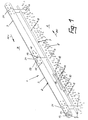
- Figures 1 to 4 and 10 is generally a Guardrail strand referred to as in particular rural, preferably wooded surroundings next to a road or - as shown in Figure 1 - between two Roads A and B with oncoming traffic according to Arrows PF and PF1 is arranged.
- the guardrail strand 1 essentially has one Spar 2 running parallel to the lanes A, B. round tree trunk sections 3.
- the spar 2 is vertical Post 4 fastened from tubes which are round in cross section, which are rammed into the ground 5.
- the surfaces the posts 4 are provided with a coating that has a wood character.
- the spar 2 is stretched in the longitudinal direction by a Steel rope 6 pulled through.
- the steel cable 6 can not in closer illustrated manner formed from steel cable sections be.
- the pipe string 7 is made from sections 8.
- the surface of the pipe string 7 also has a wood-like coating.
- the pipe string 7 is made of a tensioned steel cable 9 pulled through.
- the steel cable 9 can consist of individual steel cable sections consist.
- FIG. 1 For connecting two steel cable sections of the pipe string 7 penetrating steel cable 9 are according to FIG. 1 thread the ends of the sections 8 onto which Screw sleeves 10 are rotatable. Through the screw sockets 10 are held two half-shells 11, which are the coupling point Enclose 12 of the steel cable sections. By twisting the screw sockets 10 in the direction of the neighboring ones Posts 4 can the half-shells 11 and thus the coupling point 12 are released.
- each log section 3 consists of two vertically divided halves 13, 14. In the ends of the halves 13, 14 cross holes 15 are provided. This Cross bores 15 correspond to holes 16 in tabs 17 ( Figures 5 to 7), the height of the spar 2 in its longitudinal direction is welded like a wing to pipe socket 18 are.
- the pipe sockets 18 consist of FIGS. 5 to 7 two lengths 21 and 22.
- the top lengths 21 have an outer diameter that is the outer diameter the post 4 corresponds. Your inside diameter are smaller than the inside diameter of the posts 4 dimensioned.
- the lower lengths 22 of the pipe socket 18 are turned with respect to their outer diameter, so far that it matches the inside diameter of the posts 4 correspond. This allows the pipe socket 18 in the posts 4 are inserted positively.
- Figures 5 to 7 show that in the Upper longitudinal sections 21 transverse bores 24 are provided are traversed by the steel cable 6.
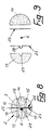
- stiffening plates 26, 27 incorporated ( Figures 2, 3, 8 and 9). They are provided in pairs.
- a stiffening plate 26 of each pair is rectangularly configured flat while the other stiffening plate 27 has a pronounced guide channel 28.
- This guide channel 28 engages in a longitudinal groove 29 a half 13 and is secured therein.
- the guide channel 28 and the longitudinal groove 29 serve to accommodate the the spar 2 pulling steel cable 6.
- the stiffening plates 26, 27 are fixed at the screwing of the halves 13, 14 with the tabs 17th
- FIGS. 1 to 4 and 10 show that the approximately in the area of the ridge-side rounding 30 of the Holms 2 lying upper ends of the posts 4 with cover caps 31 are provided. These caps 31 also have a coating with a wood character.
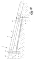
- FIG. 10 shows one end of the guardrail strand 1. It can be seen that both the spar 2 and the tubing string 7 are lowered into the floor 5. The one deepened here Arranged post 4 is also used for guying the steel cables pulling through the spar 2 and the pipe string 7 6 and 9.
Landscapes
- Engineering & Computer Science (AREA)
- Architecture (AREA)
- Civil Engineering (AREA)
- Structural Engineering (AREA)
- Aviation & Aerospace Engineering (AREA)
- Life Sciences & Earth Sciences (AREA)
- Wood Science & Technology (AREA)
- Refuge Islands, Traffic Blockers, Or Guard Fence (AREA)
- Bridges Or Land Bridges (AREA)
- Cultivation Of Seaweed (AREA)
Description
- Figur 1
- in perspektivischer Darstellung einen Abschnitt eines zwischen zwei Fahrbahnen mit Gegenverkehr angeordneten Schutzplankenstrangs;
- Figur 2
- eine Seitenansicht auf den Schutzplankenstrang der Figur 1 im Bereich zweier aufeinander folgender Pfosten;
- Figur 3
- einen vertikalen Querschnitt durch die Darstellung der Figur 2 entlang der Linie III-III;
- Figur 4
- eine Draufsicht auf den Abschnitt des Schutzplankenstrangs der Figur 2;
- Figur 5
- in vergrößerter Darstellung in der Seitenansicht den oberen Endabschnitt eines Pfostens;
- Figur 6
- den Pfosten der Figur 5 in der Stirnansicht gemäß dem Pfeil VI;
- Figur 7
- eine Draufsicht auf die Darstellung der Figur 5;
- Figur 8
- in vergrößerter Darstellung einen vertikalen Querschnitt durch den Holm des Schutzplankenstrangs entlang der Linie VIII-VIII der Figur 2;
- Figur 9
- die Darstellung der Figur 8 vor der Montage und
- Figur 10
- in der Seitenansicht einen Endabschnitt des Schutzplankenstrangs der Figur 1.
Claims (9)
- Schutzplankenstrang entlang einer Fahrbahn (A, B), der einen im wesentlichen parallel zur Fahrbahn (A, B) verlaufenden Holm (2) aus über metallische Laschen (17) miteinander verbundenen Baumstammabschnitten (3) aufweist, die von in den Boden (5) neben der Fahrbahn (A, B) eingerammten metallischen Pfosten (4) getragen und mit diesen lösbar verbunden sind, dadurch gekennzeichnet, daß die Baumstammabschnitte (3) in Längsrichtung von einem gespannten Stahlseil (6) durchzogen sind, das in den Pfosten (4), die rohrförmig mit rundem Querschnitt ausgebildet sind, lösbar gelagert ist, wobei die Pfosten (4) im Höhenbereich zwischen dem Boden (5) und dem Holm (2) durch einen zum Holm (2) parallel verlaufenden runden Rohrstrang (7) verbunden sind, in welchem sich ein gespanntes Stahlseil (9) erstreckt.
- Schutzplankenstrang nach Anspruch 1, dadurch gekennzeichnet, daß das Stahlseil (6) mit den oberen Enden der Pfosten (4) zusammengesteckte Rohrstutzen (18) quer durchsetzt.
- Schutzplankenstrang nach Anspruch 2, dadurch gekennzeichnet, daß die Rohrstutzen (18) durch Sollbruchstellen (23) mit den Pfosten (4) verbunden sind.
- Schutzplankenstrang nach einem der Ansprüche 1 bis 3, dadurch gekennzeichnet, daß jeder Baumstammabschnitt (3) aus zwei vertikal geteilten Hälften (13, 14) besteht, deren Enden über mittelbar von den Pfosten (4) in Längsrichtung des Holms (2) flügelartig abstehende Laschen (17) miteinander und mit den Pfosten (4) verschraubt sind.
- Schutzplankenstrang nach Anspruch 4, dadurch gekennzeichnet, daß im Bereich zwischen zwei aufeinander folgenden Pfosten (4) Versteifungsbleche (26, 27) in den Spalt (25) zwischen die Hälften (13, 14) eingegliedert sind.
- Schutzplankenstrang nach Anspruch 5, dadurch gekennzeichnet, daß jeweils zwei Versteifungsbleche (26, 27) paarweise einander zugeordnet sind, wobei in mindestens einem Versteifungsblech (27) ein in Längsrichtung des Holms (2) verlaufender Führungskanal (28) für das Stahlseil (6) ausgeprägt ist, der in eine Längsnut (29) einer Hälfte (13) greift.
- Schutzplankenstrang nach einem der Ansprüche 1 bis 6, dadurch gekennzeichnet, daß der die Pfosten (4) verbindende Rohrstrang (7) mit Koppelstellen (12) für Stahlseilabschnitte versehen ist.
- Schutzplankenstrang nach einem der Ansprüche 1 bis 7, dadurch gekennzeichnet, daß die etwa im Bereich firstseitiger Rundungen (30) des Holms (2) liegenden oberen Enden der Pfosten (4) mit Abdeckkappen (31) versehen sind.
- Schutzplankenstrang nach einem der Ansprüche 1 bis 8, dadurch gekennzeichnet, daß die Enden des Holms (2) und des Rohrstrangs (7) in den Boden (5) versenkt sind.
Applications Claiming Priority (2)
| Application Number | Priority Date | Filing Date | Title |
|---|---|---|---|
| DE19517933A DE19517933C2 (de) | 1995-05-18 | 1995-05-18 | Schutzplankenstrang |
| DE19517933 | 1995-05-18 |
Publications (2)
| Publication Number | Publication Date |
|---|---|
| EP0743398A1 EP0743398A1 (de) | 1996-11-20 |
| EP0743398B1 true EP0743398B1 (de) | 1999-01-27 |
Family
ID=7762047
Family Applications (1)
| Application Number | Title | Priority Date | Filing Date |
|---|---|---|---|
| EP96107757A Expired - Lifetime EP0743398B1 (de) | 1995-05-18 | 1996-05-15 | Schutzplankenstrang |
Country Status (3)
| Country | Link |
|---|---|
| EP (1) | EP0743398B1 (de) |
| AT (1) | ATE176287T1 (de) |
| DE (2) | DE19517933C2 (de) |
Families Citing this family (11)
| Publication number | Priority date | Publication date | Assignee | Title |
|---|---|---|---|---|
| DE19757092C2 (de) | 1997-12-20 | 2002-12-05 | Spig Schutzplanken Prod Gmbh | Schutzplankenstrang |
| DE29817773U1 (de) * | 1998-09-21 | 1998-12-24 | Meißner, Rico, 04895 Falkenberg | Ortsveränderliche Leitwand |
| DE10326414B3 (de) | 2003-06-12 | 2004-08-26 | Spig Schutzplanken-Produktions-Gesellschaft Mbh & Co Kg | Schutzplankenstrang |
| EP1486614A1 (de) | 2003-06-12 | 2004-12-15 | SPIG Schutzplanken-Produktions-Gesellschaft mbH & Co.KG | Schutzplankenstrang |
| DE102005039705A1 (de) * | 2005-05-10 | 2006-11-16 | Durabel Baubedarf Gmbh | Verkehrs-Leit-Einrichtung |
| DE202006004364U1 (de) * | 2005-08-19 | 2006-06-08 | SGGT Straßenausstattungen GmbH | Schutzplankenstrang |
| DE102007048095A1 (de) * | 2007-10-05 | 2009-04-23 | Heintzmann Sicherheitssysteme Gmbh & Co. Kg | Pfosten für einen Schutzplankenstrang |
| DE102011007536A1 (de) * | 2011-04-15 | 2012-10-18 | Stahlwerk Annahütte Max Aicher GmbH & Co KG | Verkehrs-Leit-System mit Aussteifungs-Elementen |
| DE202015104733U1 (de) * | 2015-06-04 | 2015-10-01 | Jürgen Hinrichsen | Rückhaltesystem an Verkehrswegen |
| CN107700387A (zh) * | 2017-10-11 | 2018-02-16 | 佛山市圣田智能科技有限公司 | 一种用于防护栏的加强结构 |
| WO2021067652A1 (en) * | 2019-10-03 | 2021-04-08 | Mccue Corporation | Barrier with cable system |
Family Cites Families (11)
| Publication number | Priority date | Publication date | Assignee | Title |
|---|---|---|---|---|
| US2085058A (en) * | 1934-03-12 | 1937-06-29 | Wood Henry Allyn | Guardrail |
| US2337626A (en) * | 1941-11-24 | 1943-12-28 | Emerson D Sawyer | Balustrade |
| GB1272588A (en) * | 1968-09-04 | 1972-05-03 | British Ropes Ltd | Improvements in or relating to vehicle retention barriers |
| CH542957A (de) * | 1972-04-06 | 1973-10-15 | Walser & Co | Autofahrbahnbegrenzungseinrichtung |
| DE8426717U1 (de) * | 1984-09-11 | 1985-01-24 | SPIG Schutzplanken-Produktions-Gesellschaft mbH & Co KG, 6612 Schmelz | Pfosten fuer eine leitplankenkonstruktion |
| ES2010192T5 (es) * | 1985-12-23 | 1995-11-01 | Francaise Des Etablissements G | Vallas de seguridad para carretera. |
| FR2683840B1 (fr) * | 1991-11-19 | 1994-02-18 | Boyer Sa | Glissiere de securite routiere. |
| FR2690701B1 (fr) * | 1992-04-30 | 1996-09-20 | Daniel Duyck | Glissieres de securite routieres mixtes metal et bois ronds armes. |
| FR2690937B1 (fr) * | 1992-05-07 | 1994-12-23 | Emc2 | Glissière de sécurité à ossature bois renforcée. |
| US5354037A (en) * | 1992-08-28 | 1994-10-11 | Frank Venegas, Jr. | Multiple design guardrail system |
| FR2703706B1 (fr) * | 1993-04-07 | 1995-06-23 | Cihb | Glissiere ou barriere de securite routiere bois-metal. |
-
1995
- 1995-05-18 DE DE19517933A patent/DE19517933C2/de not_active Expired - Fee Related
-
1996
- 1996-05-15 AT AT96107757T patent/ATE176287T1/de not_active IP Right Cessation
- 1996-05-15 EP EP96107757A patent/EP0743398B1/de not_active Expired - Lifetime
- 1996-05-15 DE DE59601209T patent/DE59601209D1/de not_active Expired - Fee Related
Also Published As
| Publication number | Publication date |
|---|---|
| DE19517933A1 (de) | 1996-11-21 |
| ATE176287T1 (de) | 1999-02-15 |
| DE59601209D1 (de) | 1999-03-11 |
| EP0743398A1 (de) | 1996-11-20 |
| DE19517933C2 (de) | 2000-02-03 |
Similar Documents
| Publication | Publication Date | Title |
|---|---|---|
| DE69301857T2 (de) | Leitplanken aus Holz und Metall | |
| DE3816528C2 (de) | ||
| DE4224998C1 (en) | Protective crash barrier for highways - comprises posts anchored in ground, deformation profile on road side, upper and lower longitudinal rails | |
| EP1762660B1 (de) | Verkehrs-Leit-Einrichtung | |
| DE2707704A1 (de) | Metallgelaender | |
| DE19517933C2 (de) | Schutzplankenstrang | |
| CH636663A5 (en) | Road barrier device for keeping vehicles on a road | |
| EP1926859B1 (de) | Schutzplankenstrang | |
| DE3809896A1 (de) | Schutzplankenanordnung fuer fahrbahnen | |
| EP1630295B1 (de) | Passive Schutzeinrichtung neben einer Fahrbahn einer Kraftfahrzeugstrasse | |
| EP1486615B1 (de) | Schutzplankenstrang | |
| DE19536915C2 (de) | Schutzplankenanordnung | |
| EP1177348A1 (de) | Leitwand für verkehrswege | |
| CH664588A5 (de) | Leitplankenkonstruktion. | |
| DE9405557U1 (de) | Leitplanke oder Straßensicherheitsbarriere | |
| DE29604226U1 (de) | Schutzplankenanordnung | |
| EP0924346B1 (de) | Schutzplankenstrang | |
| EP1486614A1 (de) | Schutzplankenstrang | |
| EP0761889B1 (de) | Schutzplankenanordnung | |
| EP0596405B1 (de) | Leiteinrichtung mit Fussplanken aus Beton | |
| DE102011055960A1 (de) | Fahrzeugrückhaltesystem | |
| DE4403438A1 (de) | Leitwand für Kraftfahrzeuge | |
| EP1693518B1 (de) | Schutzplankenstrang | |
| DE9212640U1 (de) | Leitplanke aus Beton mit waagrechten Durchbrüchen | |
| EP1876300B1 (de) | Schutzplankenstrang aus Stahl |
Legal Events
| Date | Code | Title | Description |
|---|---|---|---|
| PUAI | Public reference made under article 153(3) epc to a published international application that has entered the european phase |
Free format text: ORIGINAL CODE: 0009012 |
|
| 17P | Request for examination filed |
Effective date: 19960902 |
|
| AK | Designated contracting states |
Kind code of ref document: A1 Designated state(s): AT CH DE FR LI |
|
| GRAG | Despatch of communication of intention to grant |
Free format text: ORIGINAL CODE: EPIDOS AGRA |
|
| GRAG | Despatch of communication of intention to grant |
Free format text: ORIGINAL CODE: EPIDOS AGRA |
|
| GRAH | Despatch of communication of intention to grant a patent |
Free format text: ORIGINAL CODE: EPIDOS IGRA |
|
| 17Q | First examination report despatched |
Effective date: 19980710 |
|
| GRAH | Despatch of communication of intention to grant a patent |
Free format text: ORIGINAL CODE: EPIDOS IGRA |
|
| GRAA | (expected) grant |
Free format text: ORIGINAL CODE: 0009210 |
|
| AK | Designated contracting states |
Kind code of ref document: B1 Designated state(s): AT CH DE FR LI |
|
| REF | Corresponds to: |
Ref document number: 176287 Country of ref document: AT Date of ref document: 19990215 Kind code of ref document: T |
|
| REG | Reference to a national code |
Ref country code: CH Ref legal event code: EP |
|
| REF | Corresponds to: |
Ref document number: 59601209 Country of ref document: DE Date of ref document: 19990311 |
|
| REG | Reference to a national code |
Ref country code: CH Ref legal event code: NV Representative=s name: PATENTANWAELTE SCHAAD, BALASS, MENZL & PARTNER AG |
|
| ET | Fr: translation filed | ||
| PLBE | No opposition filed within time limit |
Free format text: ORIGINAL CODE: 0009261 |
|
| STAA | Information on the status of an ep patent application or granted ep patent |
Free format text: STATUS: NO OPPOSITION FILED WITHIN TIME LIMIT |
|
| 26N | No opposition filed | ||
| PGFP | Annual fee paid to national office [announced via postgrant information from national office to epo] |
Ref country code: FR Payment date: 20090427 Year of fee payment: 14 Ref country code: DE Payment date: 20090409 Year of fee payment: 14 Ref country code: AT Payment date: 20090313 Year of fee payment: 14 |
|
| PGFP | Annual fee paid to national office [announced via postgrant information from national office to epo] |
Ref country code: CH Payment date: 20090518 Year of fee payment: 14 |
|
| REG | Reference to a national code |
Ref country code: CH Ref legal event code: PL |
|
| PG25 | Lapsed in a contracting state [announced via postgrant information from national office to epo] |
Ref country code: AT Free format text: LAPSE BECAUSE OF NON-PAYMENT OF DUE FEES Effective date: 20100515 |
|
| REG | Reference to a national code |
Ref country code: FR Ref legal event code: ST Effective date: 20110131 |
|
| PG25 | Lapsed in a contracting state [announced via postgrant information from national office to epo] |
Ref country code: LI Free format text: LAPSE BECAUSE OF NON-PAYMENT OF DUE FEES Effective date: 20100531 Ref country code: CH Free format text: LAPSE BECAUSE OF NON-PAYMENT OF DUE FEES Effective date: 20100531 |
|
| PG25 | Lapsed in a contracting state [announced via postgrant information from national office to epo] |
Ref country code: DE Free format text: LAPSE BECAUSE OF NON-PAYMENT OF DUE FEES Effective date: 20101201 |
|
| PG25 | Lapsed in a contracting state [announced via postgrant information from national office to epo] |
Ref country code: FR Free format text: LAPSE BECAUSE OF NON-PAYMENT OF DUE FEES Effective date: 20100531 |