EP0738409B1 - Leerflaschen-rücknahmegerät - Google Patents
Leerflaschen-rücknahmegerät Download PDFInfo
- Publication number
- EP0738409B1 EP0738409B1 EP95904432A EP95904432A EP0738409B1 EP 0738409 B1 EP0738409 B1 EP 0738409B1 EP 95904432 A EP95904432 A EP 95904432A EP 95904432 A EP95904432 A EP 95904432A EP 0738409 B1 EP0738409 B1 EP 0738409B1
- Authority
- EP
- European Patent Office
- Prior art keywords
- bottle
- empty bottle
- empty
- collector according
- slide
- Prior art date
- Legal status (The legal status is an assumption and is not a legal conclusion. Google has not performed a legal analysis and makes no representation as to the accuracy of the status listed.)
- Expired - Lifetime
Links
Images
Classifications
-
- G—PHYSICS
- G07—CHECKING-DEVICES
- G07F—COIN-FREED OR LIKE APPARATUS
- G07F7/00—Mechanisms actuated by objects other than coins to free or to actuate vending, hiring, coin or paper currency dispensing or refunding apparatus
- G07F7/06—Mechanisms actuated by objects other than coins to free or to actuate vending, hiring, coin or paper currency dispensing or refunding apparatus by returnable containers, i.e. reverse vending systems in which a user is rewarded for returning a container that serves as a token of value, e.g. bottles
- G07F7/0609—Mechanisms actuated by objects other than coins to free or to actuate vending, hiring, coin or paper currency dispensing or refunding apparatus by returnable containers, i.e. reverse vending systems in which a user is rewarded for returning a container that serves as a token of value, e.g. bottles by fluid containers, e.g. bottles, cups, gas containers
Definitions
- the invention relates to an empty bottle return device a housing with at least one lockable Entry opening accessible from outside for empty bottles, with an adjoining the input chamber Empty bottle magazine, with a motor-driven Conveyor, one through the input chamber taking the set empty bottle in the direction Empty bottle magazine on a linear displacement path has sliding bottle pushers, with a device located in the area of the input chamber for bottle detection, which is linear within the housing sliding back and forth, the displacement path of the bottle pusher Sensor slides crossing in the area of the input chamber which has a sensor for scanning the bottle contour and / or the bottle diameter is, and preferably with an output signal the control device responsive to the bottle detection device to control the conveyor and, if necessary a deposit payment, the input chamber a Space to hold an upright empty bottle and the empty bottle magazine one at the level of Magazine shelf to accommodate upright have standing empty bottles.
- An empty bottle return device of this type is known (WO 85/05207), in which the conveyor means a through the input chamber, taking the set one with it Empty bottle towards empty bottle magazine on a linear Sliding and sliding bottle slider has, while the bottle detection device several linearly sliding back and forth within the housing, the displacement of the bottle pusher in the area of Input chamber has intersecting sensor slides, which with a sensor for scanning the bottle diameter are.
- the sensors are designed there as mechanical probes, the diametrically opposite sides strike against the surface of the bottle.
- EP-A2-567 732 are the empty bottles in different Levels via separately loadable input chambers entered into stationary magazine compartments.
- a separate bottle detection device is provided, with the contour of the set empty bottle with in the input chamber engaging mechanical feelers scanned becomes.
- the scanning takes place with the help of a Displacement movement of the sliding door responsive encoder, one with the output signals of the displacement sensor
- Counters and storage means for storing counter readings of the counter in the form of a contour and size the value group defining the scanned empty bottle are.
- the sensing elements are arranged on the sliding door and reach into the input chamber to trigger displacement, Counting and storing processes.
- the empty bottles will after being scanned using one in the input chamber located turnstile via a curved feed channel transported into the empty bottle magazine. Once the magazine is full, it must be taken on the spot by individual removal the bottles are emptied.
- the invention is based on the object an empty bottle return device of the type specified at the beginning to develop that easy handling when loading and emptying possible despite the high input frequency reliable bottle detection guaranteed.
- the solution according to the invention is primarily based on the idea that with a small displacement between the Input chamber and the empty bottle magazine on as straight as possible Displacement distance and with a non-contact Scanning of the bottle contour particularly short input times can be achieved.
- the empty bottle magazine over a lockable aligned transversely to the input opening Access opening accessible from the stationary input chamber is and that the conveyor a transverse to Entry direction through the entry chamber with entrainment the set empty bottle in the direction of the passage opening can be pushed back and forth on a linear displacement path Cross slide has.
- the bottle detection device also one inside the housing
- the input direction can be moved back and forth linearly, the displacement path of the cross slide in the area of the input chamber crossing sensor slide on, with sensors for contactless Scanning the bottle contour and / or the bottle diameter is equipped, the drive of the sensor slide with a displacement sensor triggered by the sensors is coupled for bottle detection.
- the sensor slide one at the same time as a closing door for the passage opening trained side arm.
- this boom can either receive and send organs or reflection mirrors designed as light barriers Sensors.
- the invention provides that the sensor slide on the side of the shutter door bracket opposite the Input chamber a second, preferably the sensor elements has supporting boom. The second boom can do this through a housing-side boundary wall of the input chamber be concealed, the lateral boundary wall in the direction of displacement of the sensor slide can have elongated sensor diaphragms.
- the sensors are advantageously optoelectronic Scanning elements, preferably as reflection or transmitted light barriers educated.
- the bottle detection device in the area of the cross slide fixed to the housing between the input chamber and the passage opening Arranged sensors for contactless bottle scanning and one with the cross slide or its drive coupled displacement sensors triggered by the sensors Detection of the bottle contour and / or the bottle diameter on.
- a sensor slide in the sense of the first alternative of the invention is unnecessary here.
- a particularly simple embodiment in terms of construction stipulates that the on the housing Empty bottle placed by the motor driven cross slide detected and on the displacement through the sensor arrangement into the empty bottle magazine is moved. In this case also non-refundable bottles in the empty bottle magazine since the bottle detection during the Eject the empty bottle into the empty bottle magazine he follows. To reject this solution To allow non-refundable bottles, additional must Measures are taken with which the Empty bottle after scanning it back into the input chamber can be retrieved.
- the invention proposed that the cross slide a platform for inclusion in the input chamber has set empty bottle that with the cross slide over the displacement path to the passage opening slidable or through it Can be inserted into the empty bottle magazine and after delivery the empty bottle can be returned to its starting position is. It is also useful to have a the passage opening or arranged on the cross slide, motorized bottle scraper intended for the empty bottle arranged on the platform, one after the control device In accordance with an output signal of the bottle detection device operable drive motor. Of the Bottle scraper is only activated if a permissible via the bottle detection device and / or depositable bottle to the control device is reported. An unapproved empty bottle will work again without actuating the bottle scraper withdrawn via the cross slide into the input chamber, at the same time signaling that an entry this bottle is not possible.
- the bottle scraper can also act as a closing door be designed for the passage opening. Is further it is appropriate to keep the input chamber open to the side of the passage opening and the sensors limit by a partition that is perpendicular to the Direction of displacement of the cross slide is displaceable. This partition is advantageously with the scraper rigidly connected and movable together with it. On the opposite of the passage opening Side is useful on the cross slide or on the platform a cross slide-proof, delimiting the input chamber vertical side wall provided.
- the input chamber can through a housing-fixed rear stop wall for the empty bottles are limited.
- Another improvement the positioning accuracy of the empty bottle in the input chamber is achieved in that the footprint the input chamber by a housing-fixed front and rear limit threshold limited is.
- the bottle weight can be used as a further bottle recognition feature equivalent to the contour features be made available with which Full bottles and empty bottles as well as bottles of approximately the same Contour but different weights apart can be.
- the pressure sensor can designed as a pressure sensitive resistor or capacitor be. It is useful in an RC element Integrator circuit arranged, the output signal via a threshold switch or a comparator into a rectangular pulse with weight-dependent Pulse duration can be implemented.
- a particularly simple and quick bottle exchange is achieved in that the empty bottle magazine in one that can be inserted into a magazine chamber of the housing Chassis is arranged. Another improvement is achieved in this regard if the housing at least two stacked one on top of the other Sensor slide and a cross slide equipped Input chambers and the chassis a corresponding Number of empty bottle magazines arranged one above the other has, the magazine bottoms of the empty bottle magazines with the chassis set in the magazine chamber with the spaces of the associated input chambers swear.
- Chassis and / or at least on one side of the housing leading or arranged on the side of the input chambers Support rollers are provided over which the chassis when entering the magazine chamber with its castors from the floor to a defined position within the Housing can be lifted off.
- the magazine bottoms expediently have one rectangular border as a stop for the Empty bottles on.
- the fill level can in the opposite of the passage opening Border margin area on a pushed-on empty bottle attractive, preferably housing-fixed sensor element can be arranged, for example, as around a vertical axis pivotable lever is formed can be one in the beam path of a reflection light barrier arranged reflector carries or Microswitch actuated.
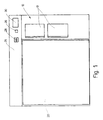
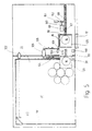
- the empty bottle return device shown in the drawing consists essentially of a housing 10, two arranged one above the other in the housing, on one Entry opening 11 can be closed by a sliding door 12 Input chambers 14 for upright Empty bottles 16, one in a magazine chamber open to the front 18 of the housing adjustable chassis 20 with two empty bottle magazines arranged one above the other 22, and a control panel 24 with receipt button 26, Receipt 28 and display 30.
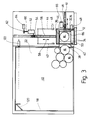
- the housing-fixed footprint 32 forward and backward through an adjustment threshold 34 and a rear stop wall 36 is limited.
- the footprint 32 of the input chambers 14 is via a passage opening 38 with the neighboring Empty bottle magazine 22 of the chassis 20 connected and aligns with the magazine bottom 40.
- the passage opening 38 is through that at the same time as a sliding door trained boom 42 of the sensor slide 44 closable.
- One opposite the first boom 42 Boom 46 of the sensor slide carries nearby its front end several, as optoelectronic Transceivers trained sensors 48 that together with the mirrors 50 on the bracket 42 reflection light barriers form for scanning the bottle contour.
- the Sensor slide 44 is by means of a geared motor 52, a gear 54 and a rack 56 between a front, shown in solid lines Input position and a rear, in dashed lines Lines shown end position horizontally in the direction of the double arrow 58 to and fro.
- the Empty bottle 16 remains when the sensor slide is moved 44 on their footprint 32 in the input chamber 14 stand.
- the sensors move on the shifting distance 48 past the bottle and feel its diameter at different heights above the footprint 32.
- the gear motor 52 drives with its output shaft 60 one as a gear 62 made of magnetizable material and a magnetic probe 64 formed incremental Sensor in cooperation with the Sensors 48 contributes to bottle detection.
- the sliding door arm 42 gives the end position of the sensor slide 44 clear the passage opening 38. In this end position, the one in the input chamber 14 located empty bottle 16 with the help of a motor 66 driven cross slide 68, the displacement of the sensor slide 44 in the area of the input chamber 14 crosses through the passage opening 38 are pushed out into the empty bottle magazine 22.
- the input chamber 14 is when the cross slide is retracted 68 in the lower part by the slider stamp 116 while limited by either the upper part a housing-fixed or by a sensor slide fixed Boundary wall is limited. If necessary in stamp 116 and in the boundary wall above Sensor screens, not shown, for the Cut out passage of the sensor light.
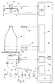
- the footprint 32 of the input chamber 14 is a surface a weighing plate 70 formed with her Bottom against a pressure-dependent resistor 72 acts.
- the resistor 72 forms together with the capacitor 76 which can be bridged by a switch 74 an integrator circuit formed by a comparator 78 is completed.
- a square wave signal can be tapped, the pulse duration after Open switch 74 via the pressure dependent resistor 72 forms a measure of the bottle weight.
- the output signal of the comparator 78 is in a timing element 80 of the microprocessor circuit 82 under formation of comparison values for weight detection evaluated.
- the gear motor 52 a relative movement between the sensor slide 44 and the sensors 48 arranged thereon on the one hand and the empty bottle located in the input chamber 14 16 on the other hand and thus a contour recognition process initiated.
- Decisive for the contour of the empty bottle 16 are the diameters in the different Measurement planes of the sensors 48, the determination of the of the respective diameter the entry and exit points to be used. As can be seen from Fig. 4, this will be in the incremental encoder encoder 84 62.64 converted count signal to the count input a counter 86 integrated in the microprocessor 82, where the beginning and end of the counting process can be determined using the limit switches 88.90.
- the trigger switches 92.94 for the cross slide drive 66.68, the signal lamps 96.98, the locking magnet 100 for the sliding door 12 and the switch 102 via output ports 104 of the microprocessor circuit 82 controllable.
- the state of the input ports 80,86,105 is queried cyclically via a microprocessor program.
- the query cycle corresponds to the program cycle frequency, which in any case is greater than the counting frequency of the encoder 62.64 must be selected.
- the incoming signals are evaluated via a Software program stored in the memory 106 of the microprocessor 82 using also in one Part of the memory 106 stored reference value sets.
- the cross slide 68 is with the help of the gear motor 66, a Gear 67 and a rack 68 between a rear, Input position shown in solid lines and a front one, in dashed lines illustrated end position horizontally in the direction of Double arrow 69 can be pushed back and forth. Furthermore drives the geared motor 66 with its output shaft 160 a as a gear 162 made of magnetizable material and a magnetic probe 164 formed incremental Displacement sensor in cooperation with the sensors 148 contributes to bottle detection.
- the cross slide 68 has a slide-resistant platform 120, which as Space for the empty bottle 16 to be set is used.
- a slide-resistant Boundary wall 116 provided while the rear wall 36 of the input chamber is arranged fixed to the housing.
- the platform 120 arrives with the one on it Bottle 16 via the displacement path through the passage opening 38 into the empty bottle magazine 22 and becomes bottle detection along the displacement path sensed by sensors 148 without contact.
- the actual transfer of the empty bottle 16 into the empty bottle magazine 22 is carried out by a scraper 124, the with the cross slide 116 extended with the aid of a drive motor 126 across the platform 120 in front of the Passage opening 38 is moved so that the subsequent Retracting the cross slide 116 Empty bottle 16 is stripped from the platform 120.
- the bottle scraper 124 is used in this embodiment at the same time as a closing door for the passage opening 42.
- a passage to the sensors 148 and to the passage opening Preventing 38 is an additional one Partition 128 provided which is rigid with the wiper 124 connected and movable together with this can be.
- the magazine bottoms 40 have a substantially rectangular shape Boundary edge 118 on that shown in the Embodiments through the vertical outer walls of the chassis 20 is formed.
- the passage openings 38 are each through a wall opening in the input side Wall area of the chassis 20 formed, under the action of a spring, not shown when removing the chassis from the magazine chamber 18 are closed automatically.
- the chassis 20 with relatively large casters 110 provided.
- the bottles are used for emptying 16 first from the top magazine bottom 40 from above removed and, if necessary, in ready-made bottle crates sorted. For emptying the lower magazine bottom 40 becomes the previously emptied upper magazine bottom 40 for example on a hinge joint folded up to freely from above to the concerned Bottles 16 to be able to get.
- the invention refers to an empty bottle return device with an input chamber 14 for empty bottles 16 and one Chassis 20 as a change magazine 22.
- To a simple Handling when loading and emptying the change magazine 22 is the empty bottle magazine 22 via an aligned transverse to the input opening 11 closable passage opening 38 from the stationary input chamber 14 accessible from. Is further a conveyor is provided which transversely to Input direction through the input chamber 14 in Can be pushed back and forth towards the passage opening 38
- Cross slide 68 has.
- the bottle is recognized via a within the housing 10 in the input direction sliding back and forth, the displacement path of the cross slide 68 in the area of the input chamber crossing sensor slide 44, which with sensors 48 for Non-contact scanning of the bottle contour is.
Landscapes
- General Physics & Mathematics (AREA)
- Physics & Mathematics (AREA)
- Sorting Of Articles (AREA)
- Control Of Vending Devices And Auxiliary Devices For Vending Devices (AREA)
- Glass Compositions (AREA)
- Magnetic Ceramics (AREA)
- Producing Shaped Articles From Materials (AREA)
- Branching, Merging, And Special Transfer Between Conveyors (AREA)
- Filling Of Jars Or Cans And Processes For Cleaning And Sealing Jars (AREA)
- Looms (AREA)
- Supplying Of Containers To The Packaging Station (AREA)
- Sink And Installation For Waste Water (AREA)
- Processing And Handling Of Plastics And Other Materials For Molding In General (AREA)
- Centrifugal Separators (AREA)
- Refuse Collection And Transfer (AREA)
- Optical Measuring Cells (AREA)
Description
- Fig. 1
- eine Frontansicht eines geschlossenen Leerflaschen-Rücknahmegeräts;
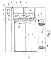
- Fig. 2
- eine Vorderansicht des Leerflaschen-Rücknahmegeräts mit abgenommener Fahrgestellblende;
- Fig. 3
- eine Draufsicht auf das Leerflaschen-Rücknahmegerät bei abgenommenem Gehäuseoberteil;
- Fig. 4
- ein Schema der Flaschenerkennungseinrichtung;
- Fig. 5
- eine Darstellung entsprechend Fig. 3 für ein abgewandeltes Ausführungsbeispiel eines Leerflaschen-Rücknahmegeräts.
Claims (28)
- Leerflaschen-Rücknahmegerät mit einem Gehäuse (10), mit mindestens einer durch eine verschließbare Eingabeöffnung (11) von außen her zugänglichen Eingabekammer (14) für Leerflaschen (16), mit einem an die Eingabekammer (14) anschließenden Leerflaschenmagazin (22), mit einer motorisch antreibbaren Fördereinrichtung (68), die einen durch die Eingabekammer (14) hindurch unter Mitnahme der eingestellten Leerflasche (16) in Richtung Leerflaschenmagazin (22) auf einem linearen Verschiebeweg hin- und herverschiebbaren Flaschenschieber (68) aufweist, mit einer im Bereich der Eingabekammer (14) befindlichen Einrichtung (44,48; 70,72) zur Flaschenerkennung, die einen innerhalb des Gehäuses (10) linear hin- und herverschiebbaren, den Verschiebeweg des Flaschenschiebers (68) im Bereich der Eingabekammer (14) kreuzenden Sensorschieber (44) aufweist, welcher mit einem Sensor (48) zur Abtastung der Flaschenkontur und/oder des Flaschendurchmessers bestückt ist, und mit einer vorzugsweise auf Ausgangssignale der Flaschenerkennungseinrichtung ansprechenden Steuereinrichtung (82) zur Ansteuerung der Fördereinrichtung (68) und gegebenenfalls einer Pfandgeldausgabe (28), wobei die Eingabekammer (14) eine Stellfläche (32) zur Aufnahme einer aufrecht stehenden Leerflasche (16) und das Leerflaschenmagazin (22) einen auf der Höhe der Stellfläche befindlichen Magazinboden (40) zur Aufnahme von aufrecht stehenden Leerflaschen (16) aufweisen, dadurch gekennzeichnet, daß das Leerflaschenmagazin (22) über eine quer zur Eingabeöffnung (11) ausgerichtete verschließbare Durchtrittsöffnung (38) von der stationären Eingabekammer (14) aus zugänglich ist, daß der Flaschenschieber als quer zur Eingaberichtung verschiebbarer Querschieber (68) ausgebildet ist, daß der Sensorschieber (44) mit Sensoren (48) zur berührungslosen Abtastung der Flaschenkontur und/oder des Flaschendurchmessers bestückt ist, und daß der Antrieb (52) des Sensorschiebers (44) mit einem über die Sensoren (48) getriggerten Wegaufnehmer (62,64) zur Flaschenerkennung gekoppelt ist.
- Leerflaschen-Rücknahmegerät nach Anspruch 1, dadurch gekennzeichnet, daß der Sensorschieber (44) einen zugleich als Verschlußtür für die Durchtrittsöffnung (38) ausgebildeten seitlichen Ausleger (42) aufweist.
- Leerflaschen-Rücknahmegerät nach Anspruch 2, dadurch gekennzeichnet, daß der Sensorschieber (44) auf der dem Ausleger (42) gegenüberliegenden Seite der Eingabekammer (14) einen zweiten, vorzugsweise die Sensoren (48) tragenden Ausleger (46) aufweist.
- Leerflaschen-Rücknahmegerät nach Anspruch 3, dadurch gekennzeichnet, daß der zweite Ausleger (46) gegenüber der Eingabekammer (14) durch eine gehäusefeste seitliche Begrenzungswand verdeckt ist.
- Leerflaschen-Rücknahmegerät nach Anspruch 4, dadurch gekennzeichnet, daß die seitliche Begrenzungswand in Verschieberichtung des Sensorschiebers (44) langgestreckte Sensorblenden aufweist.
- Leerflaschen-Rücknahmegerät nach Anspruch 4 oder 5, dadurch gekennzeichnet, daß die seitliche gehäusefeste Begrenzungswand und/oder der der Verschlußtür (42) gegenüberliegende Sensorschieber-Ausleger (46) im unteren, der Stellfläche (32) benachbarten Bereich eine Ausnehmung für den Durchtritt des Querschiebers (68,116) aufweisen.
- Leerflaschen-Rücknahmegerät nach Anspruch 6, dadurch gekennzeichnet, daß der Querschieber (68) mit seiner Stirnfläche (116) in seiner bezüglich der Durchtrittsöffnung (38) zurückverschobenen Endstellung den unteren Teil einer seitlichen Begrenzungswand der Eingabekammer (14) bildet.
- Leerflaschen-Rücknahmegerät mit einem Gehäuse (10), mit mindestens einer durch eine verschließbare Eingabeöffnung (11) von außen her zugänglichen Eingabekammer (14) für Leerflaschen (16), mit einem an die Eingabekammer (14) anschließenden Leerflaschenmagazin (22), mit einer motorisch antreibbaren Fördereinrichtung (68), die einen durch die Eingabekammer (14) hindurch unter Mitnahme der eingestellten Leerflasche (16) in Richtung Leerflaschenmagazin (22) auf einem linearen Verschiebeweg hin- und herverschiebbaren Flaschenschieber (68) aufweist, mit einer im Bereich der Eingabekammer (14) befindlichen Einrichtung (44,48; 70,72) zur Flaschenerkennung und mit einer vorzugsweise auf Ausgangssignale der Flaschenerkennungseinrichtung ansprechenden Steuereinrichtung (82) zur Ansteuerung der Fördereinrichtung (68) und gegebenenfalls einer Pfandgeldausgabe (28), wobei die Eingabekammer (14) eine Stellfläche (32) zur Aufnahme einer aufrecht stehenden Leerflasche (16) und das Leerflaschenmagazin (22) einen auf der Höhe der Stellfläche befindlichen Magazinboden (40) zur Aufnahme von aufrecht stehenden Leerflaschen (16) aufweisen, dadurch gekennzeichnet, daß das Leerflaschenmagazin (22) über eine quer zur Eingabeöffnung (11) ausgerichtete Durchtrittsöffnung (38) von der Eingabekammer (14) aus zugänglich ist, daß der Flaschenschieber als quer zur Eingaberichtung verschiebbarer Querschieber (68,116) ausgebildet ist und daß die Flaschenerkennungseinrichtung im Bereich des Verschiebewegs zwischen Eingabekammer (14) und Durchtrittöffnung (38) gehäusefest angeordnete Sensoren (148) zur berührungslosen Flaschenabtastung und einen mit dem Querschieber (68, 116) oder dessen Antrieb (66) gekoppelten, über die Sensoren (148) getriggerten Wegaufnehmer (162,164) zur Flaschenerkennung aufweist.
- Leerflaschen-Rücknahmegerät nach einem der Ansprüche 1 bis 8, dadurch gekennzeichnet, daß die Eingabekammer (14) durch eine gehäusefeste rückwärtige Anschlagwand (36) für die Leerflaschen (16) begrenzt ist.
- Leerflaschen-Rücknahmegerät nach einem der Ansprüche 1 bis 9, dadurch gekennzeichnet, daß die Stellfläche (32) der Eingabekammer (14) durch je eine gehäusefeste vordere und rückwärtige Begrenzungsschwelle (34) begrenzt ist.
- Leerflaschen-Rücknahmegerät nach einem der Ansprüche 1 bis 10, dadurch gekennzeichnet, daß die Sensoren (48) als optoelektronische Abtastorgane, vorzugsweise als Reflexions- oder Durchlicht-Lichtschranken ausgebildet sind.
- Leerflaschen-Rücknahmegerät nach einem der Ansprüche 1 bis 11, dadurch gekennzeichnet, daß die Stellfläche (32) innerhalb der Eingabekammer (14) eine ausgangsseitig mit der Steuerungseinrichtung (82) verbundene Wägeeinrichtung (70) aufweist.
- Leerflaschen-Rücknahmegerät nach Anspruch 12, dadurch gekennzeichnet, daß die Wägeeinrichtung eine Wägeplatte mit einem Drucksensor aufweist, der vorzugsweise als druckempfindlicher Widerstand (72) oder Kondensator ausgebildet ist.
- Leerflaschen-Rücknahmegerät nach Anspruch 13, dadurch gekennzeichnet, daß der Drucksensor in einem RC-Glied (72,76) einer Integratorschaltung angeordnet ist, deren Ausgangssignal über einen Schwellenwertschalter oder einen Komparator (78) in einen Rechteckimpuls mit flaschengewichtsabhängiger Impulsdauer umsetzbar ist.
- Leerflaschen-Rücknahmegerät nach einem der Ansprüche 8 bis 14, dadurch gekennzeichnet, daß der Querschieber (68) eine Plattform (120) zur Aufnahme der in die Eingabekammer (14) eingestellten Leerflasche (16) aufweist, die mit dem Querschieber über den Verschiebeweg bis zur Durchtrittsöffnung (38) verschiebbar oder durch diese hindurch in das Leerflaschenmagazin (22) einführbar und - ggf. nach Übergabe der Leerflasche (16) - in seine Ausgangsstellung zurückführbar ist.
- Leerflaschen-Rücknahmegerät nach Anspruch 15, gekennzeichnet durch einen im Bereich der Durchtrittsöffnung (38) angeordneten, motorisch angetriebenen Flaschenabstreifer (124) für die auf der in das Leerflaschenmagazin (22) eingreifenden Plattform (120) angeordnete Leerflasche (16).
- Leerflaschen-Rücknahmegerät nach Anspruch 16, dadurch gekennzeichnet, daß der Flaschenabstreifer (124) zugleich als Verschlußtür für die Durchtrittsöffnung (38) ausgebildet ist.
- Leerflaschen-Rücknahmegerät nach Anspruch 15, dadurch gekennzeichnet, daß der Querschieber (68) einen vorzugsweise motorisch angetriebenen, die Leerflasche (16) von der Plattform (120) in das Leerflaschenmagazin (22) verschiebenden Flaschenabstreifer aufweist.
- Leerflaschen-Rücknahmegerät nach einem der Ansprüche 16 bis 18, dadurch gekennzeichnet, daß der Flaschenabstreifer (124) einen über die Steuerungseinrichtung (82) nach Maßgabe eines Ausgangssignals der Flaschenerkennungseinrichtung betätigbaren Antriebsmotor (126) aufweist.
- Leerflaschen-Rücknahmegerät nach einem der Ansprüche 15 bis 19, dadurch gekennzeichnet, daß die Plattform (120) auf ihrer der Durchtrittsöffnung (38) gegenüberliegenden Seite eine querschieberfeste, die Eingabekammer begrenzende vertikale Seitenwand (122) aufweist.
- Leerflaschen-Rücknahmegerät nach einem der Ansprüche 15 bis 20, gekennzeichnet durch eine die Eingabekammer (14) zur Seite der Durchtrittsöffnung (38) und der Sensoren (148) hin begrenzende, senkrecht zur Verschieberichtung des Querschiebers verschiebbare Trennwand (128) aufweist.
- Leerflaschen-Rücknahmegerät nach Anspruch 21, dadurch gekennzeichnet, daß die Trennwand (128) mit dem Flaschenabstreifer (124) starr verbunden und gemeinsam mit diesem verschiebbar ist.
- Leerflaschen-Rücknahmegerät nach einem der Ansprüche 1 bis 22, dadurch gekennzeichnet, daß das Leerflaschenmagazin (22) in einem in eine Magazinkammer (18) einschiebbaren Fahrgestell (20) angeordnet ist.
- Leerflaschen-Rücknahmegerät nach Anspruch 23, gekennzeichnet durch am Fahrgestell (20) und/oder am Gehäuse zumindest einseitig auf der Seite der Eingabekammer (14) angeordnete Leit- oder Stützrollen (112), über die das Fahrgestell (20) beim Einfahren in die Magazinkammer (18) mit ihren Fahrrollen (110) vom Boden (108) in eine definierte Position innerhalb des Gehäuses (10) abhebbar ist.
- Leerflaschen-Rücknahmegerät nach einem der Ansprüche 23 und 24, dadurch gekennzeichnet, daß das Gehäuse mindestens zwei übereinander angeordnete, mit je einem Sensorschieber (44) und/oder einem Querschieber (68) ausgestattete Eingabekammern (14) und das Fahrgestell (20) eine entsprechende Anzahl übereinander angeordnete Leerflaschenmagazine (22) aufweist, wobei die Magazinböden (40) der Leerflaschenmagazine (22) bei in die Magazinkammer (18) eingestelltem Fahrgestell (20) mit den Stellflächen (32) der zugehörigen Eingabekammern (14) fluchten.
- Leerflaschen-Rücknahmegerät nach einem der Ansprüche 1 bis 25, dadurch gekennzeichnet, daß die Magazinböden (40) einen vorzugsweise durch vertikale Fahrgestellwände gebildeten, im wesentlichen rechteckigen Begrenzungsrand aufweisen, und daß in dem der Durchtrittsöffnung (38) gegenüberliegenden Begrenzungsrandbereich ein auf eine aufgeschobene Leerflasche (16) ansprechendes, vorzugsweise gehäusefestes Sensorelement (120) angeordnet ist.
- Leerflaschen-Rücknahmegerät nach Anspruch 26, dadurch gekennzeichnet, daß das Sensorelement (120) als vorzugsweise um eine vertikale Achse gegen die Kraft einer Feder verschwenkbarer Hebel ausgebildet ist, der einen im Strahlengang einer Reflexionslichtschranke angeordneten Reflektor trägt oder einen Mikroschalter betätigt.
- Leerflaschen-Rücknahmegerät nach Anspruch 26 oder 27, dadurch gekennzeichnet, daß das Sensorelement (120) im Bereich einer Randecke der Magazinböden (40) angeordnet ist, und daß die Durchtrittsöffnung (38) an ihrem zugehörigen Begrenzungsrand in Richtung zur diagonal gegenüberliegenden Begrenzungsrandecke hin außermittig versetzt angeordnet ist.
Priority Applications (1)
| Application Number | Priority Date | Filing Date | Title |
|---|---|---|---|
| EP97111001A EP0802511B1 (de) | 1994-01-07 | 1994-12-07 | Leerflaschen-Rücknahmegerät |
Applications Claiming Priority (3)
| Application Number | Priority Date | Filing Date | Title |
|---|---|---|---|
| DE4400251 | 1994-01-07 | ||
| DE4400251 | 1994-01-07 | ||
| PCT/EP1994/004074 WO1995019020A1 (de) | 1994-01-07 | 1994-12-07 | Leerflaschen-rücknahmegerät |
Related Child Applications (1)
| Application Number | Title | Priority Date | Filing Date |
|---|---|---|---|
| EP97111001A Division EP0802511B1 (de) | 1994-01-07 | 1994-12-07 | Leerflaschen-Rücknahmegerät |
Publications (2)
| Publication Number | Publication Date |
|---|---|
| EP0738409A1 EP0738409A1 (de) | 1996-10-23 |
| EP0738409B1 true EP0738409B1 (de) | 1998-03-18 |
Family
ID=6507528
Family Applications (2)
| Application Number | Title | Priority Date | Filing Date |
|---|---|---|---|
| EP95904432A Expired - Lifetime EP0738409B1 (de) | 1994-01-07 | 1994-12-07 | Leerflaschen-rücknahmegerät |
| EP97111001A Expired - Lifetime EP0802511B1 (de) | 1994-01-07 | 1994-12-07 | Leerflaschen-Rücknahmegerät |
Family Applications After (1)
| Application Number | Title | Priority Date | Filing Date |
|---|---|---|---|
| EP97111001A Expired - Lifetime EP0802511B1 (de) | 1994-01-07 | 1994-12-07 | Leerflaschen-Rücknahmegerät |
Country Status (10)
| Country | Link |
|---|---|
| US (1) | US5788045A (de) |
| EP (2) | EP0738409B1 (de) |
| JP (1) | JP2997317B2 (de) |
| AT (2) | ATE164248T1 (de) |
| CA (1) | CA2179806A1 (de) |
| DE (3) | DE59405496D1 (de) |
| ES (1) | ES2115354T3 (de) |
| FI (1) | FI962760A7 (de) |
| NO (1) | NO314864B1 (de) |
| WO (1) | WO1995019020A1 (de) |
Cited By (2)
| Publication number | Priority date | Publication date | Assignee | Title |
|---|---|---|---|---|
| EP2256701A2 (de) | 2009-05-28 | 2010-12-01 | Sielaff Gmbh & Co. Kg Automatenbau | Leergut-Rücknahmevorrichtung und Verfahren zum Betreiben einer Leergut-Rücknahmevorrichtung |
| DE102010040177A1 (de) | 2010-09-02 | 2012-03-08 | Sielaff Gmbh & Co. Kg Automatenbau | Verkaufs- oder Rücknahmeautomat sowie Verfahren |
Families Citing this family (9)
| Publication number | Priority date | Publication date | Assignee | Title |
|---|---|---|---|---|
| WO1997012200A1 (de) * | 1995-09-28 | 1997-04-03 | Trautwein Sb-Technik Gmbh | Vorrichtung und verfahren zur durchmessererfassung von gegenständen |
| EP0895201A1 (de) * | 1997-07-31 | 1999-02-03 | Sanden Corporation | Rücknahmegerät für leere Flaschen mit reduziertem Platzbedarf für einen Flascheneingabeteil |
| DE29812678U1 (de) | 1998-07-16 | 1998-10-29 | Kiesel, Alfred, 47259 Duisburg | Rücknahmestation für Mehrwegbehälter |
| EP1150257A1 (de) | 2000-04-29 | 2001-10-31 | Prokent AG | Rücknahmeautomat für Leergutbehälter |
| DE10347565B4 (de) * | 2003-10-14 | 2006-08-10 | Wincor Nixdorf International Gmbh | Reinigungssystem für einen Rücknahmeautomaten für Leergutbehälter, Reinigungsmodul und Verfahren zum Betreiben eines Rücknahmeautomaten |
| EP1947613B1 (de) * | 2005-01-25 | 2019-08-14 | Tomra Systems ASA | Drehförderband für Pfandgegenstände |
| US8109378B2 (en) * | 2005-07-14 | 2012-02-07 | Primo Water Corporation | Bottled water distribution method and bottle return apparatus |
| DE102016000854A1 (de) * | 2016-01-27 | 2017-07-27 | Interseroh Dienstleistungs Gmbh | Mobile Zähl- und Erfassungsvorrichtung für Getränkeverpackungen |
| EP3693652B1 (de) * | 2019-02-07 | 2023-07-12 | CleanTech Swiss AG | Abfüllstation für gasflaschen und kraftfahrzeuge |
Family Cites Families (8)
| Publication number | Priority date | Publication date | Assignee | Title |
|---|---|---|---|---|
| US4248334A (en) | 1978-03-13 | 1981-02-03 | Pepsico Inc. | Recycling apparatus |
| DE3320266C2 (de) * | 1983-06-04 | 1986-01-23 | Hans-Hermann 7302 Ostfildern Trautwein | Leerflaschen-Sammel- und Abrechnungsvorrichtung |
| US4519307A (en) * | 1983-12-08 | 1985-05-28 | Aluminum Company Of America | Container recycling apparatus using scanning means to read code markings on containers |
| FR2563926B1 (fr) * | 1984-05-04 | 1986-10-10 | Dejoux Andre | Machine a deconsigner les bouteilles vides reprises par les magasins a grande surface |
| US5111927A (en) * | 1990-01-05 | 1992-05-12 | Schulze Jr Everett E | Automated recycling machine |
| DE4127238A1 (de) * | 1991-08-17 | 1993-02-18 | Trautwein Sb Technik Gmbh | Leerflaschenruecknahmegeraet |
| DE4214250A1 (de) * | 1992-04-30 | 1993-11-04 | Trautwein Sb Technik Gmbh | Leerflaschenruecknahmegeraet |
| DE4217925C2 (de) * | 1992-05-30 | 1994-10-27 | Peter Koenig | Vorrichtung zum Ansammeln von Leergut-Flaschen und zur Rückgabe von Pfandgeld |
-
1994
- 1994-12-07 DE DE59405496T patent/DE59405496D1/de not_active Expired - Fee Related
- 1994-12-07 FI FI962760A patent/FI962760A7/fi unknown
- 1994-12-07 DE DE59410102T patent/DE59410102D1/de not_active Expired - Fee Related
- 1994-12-07 AT AT95904432T patent/ATE164248T1/de not_active IP Right Cessation
- 1994-12-07 EP EP95904432A patent/EP0738409B1/de not_active Expired - Lifetime
- 1994-12-07 AT AT97111001T patent/ATE216109T1/de not_active IP Right Cessation
- 1994-12-07 JP JP7518293A patent/JP2997317B2/ja not_active Expired - Lifetime
- 1994-12-07 WO PCT/EP1994/004074 patent/WO1995019020A1/de not_active Ceased
- 1994-12-07 EP EP97111001A patent/EP0802511B1/de not_active Expired - Lifetime
- 1994-12-07 CA CA002179806A patent/CA2179806A1/en not_active Abandoned
- 1994-12-07 ES ES95904432T patent/ES2115354T3/es not_active Expired - Lifetime
- 1994-12-07 US US08/676,183 patent/US5788045A/en not_active Expired - Fee Related
- 1994-12-07 DE DE4443406A patent/DE4443406A1/de not_active Withdrawn
-
1996
- 1996-07-05 NO NO19962851A patent/NO314864B1/no unknown
Cited By (5)
| Publication number | Priority date | Publication date | Assignee | Title |
|---|---|---|---|---|
| EP2256701A2 (de) | 2009-05-28 | 2010-12-01 | Sielaff Gmbh & Co. Kg Automatenbau | Leergut-Rücknahmevorrichtung und Verfahren zum Betreiben einer Leergut-Rücknahmevorrichtung |
| DE102009026557A1 (de) | 2009-05-28 | 2010-12-02 | Sielaff Gmbh & Co. Kg Automatenbau | Leergut-Rücknahmevorrichtung und Verfahren zum Betreiben einer Leergut-Rücknahmevorrichtung |
| DE102009026557B4 (de) | 2009-05-28 | 2024-02-22 | Sielaff GmbH & Co. KG Automatenbau Herrieden | ergut-Rücknahmevorrichtung und Verfahren zum Betreiben einer Leergut-Rücknahmevorrichtung |
| DE102009026557B8 (de) | 2009-05-28 | 2024-04-18 | Sielaff GmbH & Co. KG Automatenbau Herrieden | Leergut-Rücknahmevorrichtung und Verfahren zum Betreiben einer Leergut-Rücknahmevorrichtung |
| DE102010040177A1 (de) | 2010-09-02 | 2012-03-08 | Sielaff Gmbh & Co. Kg Automatenbau | Verkaufs- oder Rücknahmeautomat sowie Verfahren |
Also Published As
| Publication number | Publication date |
|---|---|
| EP0802511A3 (de) | 1997-11-19 |
| NO314864B1 (no) | 2003-06-02 |
| JPH09507323A (ja) | 1997-07-22 |
| EP0802511B1 (de) | 2002-04-10 |
| EP0738409A1 (de) | 1996-10-23 |
| ATE216109T1 (de) | 2002-04-15 |
| NO962851D0 (no) | 1996-07-05 |
| DE59410102D1 (de) | 2002-05-16 |
| NO962851L (no) | 1996-08-22 |
| ATE164248T1 (de) | 1998-04-15 |
| DE59405496D1 (de) | 1998-04-23 |
| CA2179806A1 (en) | 1995-07-13 |
| EP0802511A2 (de) | 1997-10-22 |
| FI962760L (fi) | 1996-07-05 |
| JP2997317B2 (ja) | 2000-01-11 |
| ES2115354T3 (es) | 1998-06-16 |
| US5788045A (en) | 1998-08-04 |
| FI962760A0 (fi) | 1996-07-05 |
| FI962760A7 (fi) | 1996-07-05 |
| DE4443406A1 (de) | 1995-07-13 |
| WO1995019020A1 (de) | 1995-07-13 |
Similar Documents
| Publication | Publication Date | Title |
|---|---|---|
| EP0738409B1 (de) | Leerflaschen-rücknahmegerät | |
| EP0996935B1 (de) | Geld-ausgabeautomat | |
| DE60023986T2 (de) | Füllvorrichtung für eine feste Zubereitung | |
| EP1119830B1 (de) | Zigarettenautomat | |
| DE2117405B2 (de) | Vorrichtung zum Transport von Probefläschchen bei einem Szintillationsspektrometer | |
| DE3630191A1 (de) | Vorrichtung zur ausgabe von muenzenrollen | |
| DE4318341A1 (de) | Verfahren zur Lagerung von Stückgut, vorzugsweise von Packungen in Apotheken, und Vorrichtung zur Durchführung eines solchen Verfahrens | |
| EP0173119B1 (de) | Münzspeicher und selbstkassierender Automat | |
| DE69435014T2 (de) | Münzspeicher | |
| DE102013012763B4 (de) | Warenautomat | |
| DE4318388C2 (de) | Leerflaschenrücknahmegerät | |
| DE2758910A1 (de) | Muenztransportvorrichtung fuer spielautomaten | |
| DE69208757T2 (de) | Vorrichtung zum Zuführen von Gegenständen zu einem Müllbehälter eines Analysators | |
| DE4126258C2 (de) | Vorrichtung zur Überprüfung der Kennung eines Bechers bei Becherrücknahmeautomaten | |
| EP0290877B1 (de) | Vorrichtung zur maschinellen Rücknahme von Leergut | |
| DE19519221A1 (de) | Annahmevorrichtung für Stückgüter | |
| DE2338315C2 (de) | Wechselgeldautomat | |
| DE3787888T2 (de) | Vorrichtung zum Wechseln von Münzen. | |
| DE4435283C2 (de) | Warenausgabeautomat | |
| DE19625055A1 (de) | Vorrichtung und Verfahren zur Durchmessererfassung von Gegenständen | |
| EP1118969A1 (de) | Verkaufsautomat | |
| DE4033644C1 (en) | Cigarette group forming machine - incorporates accumulator with outlet guide system | |
| DE69618417T2 (de) | Zufuhrvorrichtung von Zuschnitten | |
| DE7312603U (de) | Flaschenrucknahmeautomat | |
| DE9321439U1 (de) | Leerflaschenrücknahmegerät |
Legal Events
| Date | Code | Title | Description |
|---|---|---|---|
| PUAI | Public reference made under article 153(3) epc to a published international application that has entered the european phase |
Free format text: ORIGINAL CODE: 0009012 |
|
| 17P | Request for examination filed |
Effective date: 19960417 |
|
| AK | Designated contracting states |
Kind code of ref document: A1 Designated state(s): AT BE CH DE ES FR GB GR IE IT LI NL SE |
|
| GRAG | Despatch of communication of intention to grant |
Free format text: ORIGINAL CODE: EPIDOS AGRA |
|
| 17Q | First examination report despatched |
Effective date: 19970131 |
|
| GRAG | Despatch of communication of intention to grant |
Free format text: ORIGINAL CODE: EPIDOS AGRA |
|
| GRAH | Despatch of communication of intention to grant a patent |
Free format text: ORIGINAL CODE: EPIDOS IGRA |
|
| RAP1 | Party data changed (applicant data changed or rights of an application transferred) |
Owner name: HANS-HERMANN TRAUTWEIN SB-TECHNIK GMBH |
|
| GRAH | Despatch of communication of intention to grant a patent |
Free format text: ORIGINAL CODE: EPIDOS IGRA |
|
| GRAA | (expected) grant |
Free format text: ORIGINAL CODE: 0009210 |
|
| AK | Designated contracting states |
Kind code of ref document: B1 Designated state(s): AT BE CH DE ES FR GB GR IE IT LI NL SE |
|
| PG25 | Lapsed in a contracting state [announced via postgrant information from national office to epo] |
Ref country code: GR Free format text: LAPSE BECAUSE OF NON-PAYMENT OF DUE FEES Effective date: 19980318 |
|
| REF | Corresponds to: |
Ref document number: 164248 Country of ref document: AT Date of ref document: 19980415 Kind code of ref document: T |
|
| XX | Miscellaneous (additional remarks) |
Free format text: TEILANMELDUNG 97111001.0 EINGEREICHT AM 02/07/97. |
|
| REG | Reference to a national code |
Ref country code: CH Ref legal event code: EP |
|
| REF | Corresponds to: |
Ref document number: 59405496 Country of ref document: DE Date of ref document: 19980423 |
|
| GBT | Gb: translation of ep patent filed (gb section 77(6)(a)/1977) |
Effective date: 19980417 |
|
| ET | Fr: translation filed | ||
| ITF | It: translation for a ep patent filed | ||
| REG | Reference to a national code |
Ref country code: ES Ref legal event code: FG2A Ref document number: 2115354 Country of ref document: ES Kind code of ref document: T3 |
|
| REG | Reference to a national code |
Ref country code: IE Ref legal event code: FG4D Free format text: 79432 |
|
| PG25 | Lapsed in a contracting state [announced via postgrant information from national office to epo] |
Ref country code: IE Free format text: LAPSE BECAUSE OF NON-PAYMENT OF DUE FEES Effective date: 19981207 Ref country code: GB Free format text: LAPSE BECAUSE OF NON-PAYMENT OF DUE FEES Effective date: 19981207 Ref country code: AT Free format text: LAPSE BECAUSE OF NON-PAYMENT OF DUE FEES Effective date: 19981207 |
|
| PG25 | Lapsed in a contracting state [announced via postgrant information from national office to epo] |
Ref country code: LI Free format text: LAPSE BECAUSE OF NON-PAYMENT OF DUE FEES Effective date: 19981231 Ref country code: CH Free format text: LAPSE BECAUSE OF NON-PAYMENT OF DUE FEES Effective date: 19981231 Ref country code: BE Free format text: LAPSE BECAUSE OF NON-PAYMENT OF DUE FEES Effective date: 19981231 |
|
| PLBE | No opposition filed within time limit |
Free format text: ORIGINAL CODE: 0009261 |
|
| STAA | Information on the status of an ep patent application or granted ep patent |
Free format text: STATUS: NO OPPOSITION FILED WITHIN TIME LIMIT |
|
| 26N | No opposition filed | ||
| BERE | Be: lapsed |
Owner name: HANS-HERMANN TRAUTWEIN SB-TECHNIK G.M.B.H. Effective date: 19981231 |
|
| PG25 | Lapsed in a contracting state [announced via postgrant information from national office to epo] |
Ref country code: NL Free format text: LAPSE BECAUSE OF NON-PAYMENT OF DUE FEES Effective date: 19990701 |
|
| GBPC | Gb: european patent ceased through non-payment of renewal fee |
Effective date: 19981207 |
|
| REG | Reference to a national code |
Ref country code: CH Ref legal event code: PL |
|
| PG25 | Lapsed in a contracting state [announced via postgrant information from national office to epo] |
Ref country code: FR Free format text: LAPSE BECAUSE OF NON-PAYMENT OF DUE FEES Effective date: 19990831 |
|
| NLV4 | Nl: lapsed or anulled due to non-payment of the annual fee |
Effective date: 19990701 |
|
| REG | Reference to a national code |
Ref country code: FR Ref legal event code: ST |
|
| PG25 | Lapsed in a contracting state [announced via postgrant information from national office to epo] |
Ref country code: ES Free format text: LAPSE BECAUSE OF NON-PAYMENT OF DUE FEES Effective date: 19991208 |
|
| PGFP | Annual fee paid to national office [announced via postgrant information from national office to epo] |
Ref country code: SE Payment date: 20011116 Year of fee payment: 8 |
|
| PG25 | Lapsed in a contracting state [announced via postgrant information from national office to epo] |
Ref country code: SE Free format text: LAPSE BECAUSE OF NON-PAYMENT OF DUE FEES Effective date: 20021208 |
|
| EUG | Se: european patent has lapsed | ||
| REG | Reference to a national code |
Ref country code: ES Ref legal event code: FD2A Effective date: 20000114 |
|
| PG25 | Lapsed in a contracting state [announced via postgrant information from national office to epo] |
Ref country code: IT Free format text: LAPSE BECAUSE OF NON-PAYMENT OF DUE FEES;WARNING: LAPSES OF ITALIAN PATENTS WITH EFFECTIVE DATE BEFORE 2007 MAY HAVE OCCURRED AT ANY TIME BEFORE 2007. THE CORRECT EFFECTIVE DATE MAY BE DIFFERENT FROM THE ONE RECORDED. Effective date: 20051207 |
|
| PGFP | Annual fee paid to national office [announced via postgrant information from national office to epo] |
Ref country code: DE Payment date: 20051222 Year of fee payment: 12 |
|
| PG25 | Lapsed in a contracting state [announced via postgrant information from national office to epo] |
Ref country code: DE Free format text: LAPSE BECAUSE OF NON-PAYMENT OF DUE FEES Effective date: 20070703 |