EP0802511B1 - Leerflaschen-Rücknahmegerät - Google Patents
Leerflaschen-Rücknahmegerät Download PDFInfo
- Publication number
- EP0802511B1 EP0802511B1 EP97111001A EP97111001A EP0802511B1 EP 0802511 B1 EP0802511 B1 EP 0802511B1 EP 97111001 A EP97111001 A EP 97111001A EP 97111001 A EP97111001 A EP 97111001A EP 0802511 B1 EP0802511 B1 EP 0802511B1
- Authority
- EP
- European Patent Office
- Prior art keywords
- empty bottle
- store
- chamber
- bottle
- empty
- Prior art date
- Legal status (The legal status is an assumption and is not a legal conclusion. Google has not performed a legal analysis and makes no representation as to the accuracy of the status listed.)
- Expired - Lifetime
Links
Images

Classifications
-
- G—PHYSICS
- G07—CHECKING-DEVICES
- G07F—COIN-FREED OR LIKE APPARATUS
- G07F7/00—Mechanisms actuated by objects other than coins to free or to actuate vending, hiring, coin or paper currency dispensing or refunding apparatus
- G07F7/06—Mechanisms actuated by objects other than coins to free or to actuate vending, hiring, coin or paper currency dispensing or refunding apparatus by returnable containers, i.e. reverse vending systems in which a user is rewarded for returning a container that serves as a token of value, e.g. bottles
- G07F7/0609—Mechanisms actuated by objects other than coins to free or to actuate vending, hiring, coin or paper currency dispensing or refunding apparatus by returnable containers, i.e. reverse vending systems in which a user is rewarded for returning a container that serves as a token of value, e.g. bottles by fluid containers, e.g. bottles, cups, gas containers
Definitions
- the invention relates to an empty bottle return device with a housing, with at least one lockable Entry opening accessible from the outside Input chamber for empty bottles with one attached to the input chamber subsequent empty bottle magazine, with a motor-driven conveyor for transport individual empty bottles from the input chamber in the empty bottle magazine, with one in the area of the input chamber located device for bottle detection and with a preferably on output signals of Bottle detection device responsive control device to control the conveyor and, if necessary a deposit payment, the input chamber a footprint to hold an upright standing empty bottle and the empty bottle magazine at the level of the shelf for holding upright empty bottles.
- Such an empty bottle return device is from the EP-A2-567 732 known.
- There the empty bottles are in different Levels via separately loadable input chambers entered into stationary magazine compartments. In every input chamber is its own bottle detection facility intended. Once the magazine is full, it must be in place and Point can be emptied by removing the bottles individually.
- the empty bottle magazine in one in a magazine chamber to arrange the retractable chassis.
- the Empty bottle magazine has one there by a chain drive adjustable in height in the chassis Magazine floor, the height of which is through the top one Limit switch touching bottle adjustable in the bottle magazine is.
- the bottles are lying in the input chamber inserted and by an acceptance rotor on a bottle pyramid forming on the magazine bottom stored. Through the automatic adjustment of the floor height it is avoided that it hits the bottles there is a glass break on the bottle pyramid. As soon as the mobile bottle magazine is full, it will exchanged for an empty magazine.
- Through the lying Bottle intake however, there is a risk of residual liquid leak out of the bottles and into one Contamination of the bottle magazine. in addition comes that randomly messed up in the bottle magazine lying bottles during the removal and the subsequent Sorting require a significant amount of work.
- the invention is based on the object an empty bottle return device at the beginning specified type to develop, which is easy to use enabled when loading and emptying the empty bottle magazine.
- the measures according to the invention make a special one simple and quick bottle replacement achieved that the empty bottle magazine in one in one Magazine chamber of the retractable chassis is arranged, the magazine bottom of the empty bottle magazine when set in the magazine chamber Chassis with the footprint of the associated input chamber flees.
- the latter is according to the invention thereby enables that on the chassis and / or on the housing at least one-sided on the input chamber side arranged guide or support rollers provided are used by the chassis when entering the Magazine chamber at least with its input chamber side Casters from the floor to a defined position within the housing can be lifted off.
- the housing has at least two on top of each other arranged, each with a sensor slide and a cross slide equipped input chambers and the chassis a corresponding number arranged one above the other Has empty bottle magazines.
- the magazine bottoms expediently have one rectangular border as a stop for the Empty bottles on.
- the fill level can in the opposite of the passage opening Border margin area on a pushed-on empty bottle attractive, preferably housing-fixed sensor element can be arranged, for example, as around a vertical axis pivotable lever is formed can be one in the beam path of a reflection light barrier arranged reflector carries or Microswitch actuated.
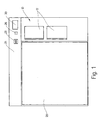
- the empty bottle return device shown in the drawing consists essentially of a housing 10, two arranged one above the other in the housing, on one Entry opening 11 can be closed by a sliding door 12 Input chambers 14 for upright Empty bottles 16, one in a magazine chamber open to the front 18 of the housing adjustable chassis 20 with two empty bottle magazines arranged one above the other 22, and a control panel 24 with receipt button 26, Receipt 28 and display 30.
- the housing-fixed footprint 32 forward and backward through an adjustment threshold 34 and a rear stop wall 36 is limited.
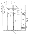
- the footprint 32 of the input chambers 14 is via a passage opening 38 with the neighboring Empty bottle magazine 22 of the chassis 20 connected and aligns with the magazine bottom 40.
- the passage opening 38 is through that at the same time as a sliding door trained boom 42 of the sensor slide 44 closable.
- One opposite the first boom 42 Boom 46 of the sensor slide carries nearby its front end several, as optoelectronic Transceivers trained sensors 48 that together with the mirrors 50 on the bracket 42 reflection light barriers form for scanning the bottle contour.
- the Sensor slide 44 is by means of a geared motor 52, a gear 54 and a rack 56 between a front, shown in solid lines Input position and a rear, in dashed lines Lines shown end position horizontally in the direction of the double arrow 58 to and fro.
- the Empty bottle 16 remains when the sensor slide is moved 44 on their footprint 32 in the input chamber 14 stand.
- the sensors move on the shifting distance 48 past the bottle and feel its diameter at different heights above the footprint 32.
- the gear motor 52 drives with its output shaft 60 one as a gear 62 made of magnetizable material and a magnetic probe 64 formed incremental Sensor in cooperation with the Sensors 48 contributes to bottle detection.
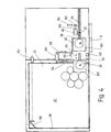
- the sliding door arm 42 gives the end position of the sensor slide 44 clear the passage opening 38. In this end position, the one in the input chamber 14 located empty bottle 16 with the help of a motor 66 driven cross slide 68, the displacement of the sensor slide 44 in the area of the input chamber 14 crosses through the passage opening 38 are pushed out into the empty bottle magazine 22.
- the input chamber 14 is when the cross slide is retracted 68 in the lower part by the slider stamp 116 while limited by either the upper part a housing-fixed or by a sensor slide fixed Boundary wall is limited. If necessary in stamp 116 and in the boundary wall above Sensor screens, not shown, for the Cut out passage of the sensor light.
- the cross slide 68 is with the help of the gear motor 66, a Gear 67 and a rack 68 between a rear, Input position shown in solid lines and a front one, in dashed lines illustrated end position horizontally in the direction of Double arrow 69 can be pushed back and forth.
- the geared motor 66 with its output shaft 160 a as a gear 162 made of magnetizable material and a magnetic probe 164 formed incremental Displacement sensor in cooperation with the sensors 148 contributes to bottle detection.
- the cross slide 68 has a slide-resistant platform 120, which as Space for the empty bottle 16 to be set is used.
- a slide-resistant Boundary wall 116 provided while the rear wall 36 of the input chamber is arranged fixed to the housing.
- the platform 120 arrives with the one on it Bottle 16 via the displacement path through the passage opening 38 into the empty bottle magazine 22 and becomes bottle detection along the displacement path sensed by sensors 148 without contact.
- the actual transfer of the empty bottle 16 into the empty bottle magazine 22 is carried out by a scraper 124, the with the cross slide 116 extended with the aid of a drive motor 126 across the platform 120 in front of the Passage opening 38 is moved so that the subsequent Retracting the cross slide 116 Empty bottle 16 is stripped from the platform 120.
- the bottle scraper 124 is used in this embodiment at the same time as a closing door for the passage opening 42.
- a passage to the sensors 148 and to the passage opening Preventing 38 is an additional one Partition 128 provided which is rigid with the wiper 124 connected and movable together with this can be.
- the magazine bottoms 40 have a substantially rectangular shape Boundary edge 118 on that shown in the Embodiments through the vertical outer walls of the chassis 20 is formed.
- the passage openings 38 are each through a wall opening in the input side Wall area of the chassis 20 formed, under the action of a spring, not shown when removing the chassis from the magazine chamber 18 are closed automatically.
- the chassis 20 with relatively large casters 110 provided.
- the bottles are used for emptying 16 first from the top magazine bottom 40 from above removed and, if necessary, in ready-made bottle crates sorted. For emptying the lower magazine bottom 40 becomes the previously emptied upper magazine bottom 40 for example on a hinge joint folded up to freely from above to the concerned Bottles 16 to be able to get.
- the invention refers to an empty bottle return device with an input chamber 14 for empty bottles 16 and one Chassis 20 as a change magazine 22.
- To a simple Handling when loading and emptying the change magazine 22 is the empty bottle magazine 22 via an aligned transverse to the input opening 11 closable passage opening 38 from the stationary input chamber 14 accessible from. Is further a conveyor is provided which transversely to Input direction through the input chamber 14 in Can be pushed back and forth towards the passage opening 38 Cross slide 68 has.
- a smooth transition between the input chamber 14 and the chassis side Precautions are to be taken to ensure magazine bottom 40 for aligning the magazine bottom with the shelf the associated input chamber at in the magazine chamber inserted chassis 20 hit.
Landscapes
- Physics & Mathematics (AREA)
- General Physics & Mathematics (AREA)
- Sorting Of Articles (AREA)
- Control Of Vending Devices And Auxiliary Devices For Vending Devices (AREA)
- Glass Compositions (AREA)
- Producing Shaped Articles From Materials (AREA)
- Magnetic Ceramics (AREA)
- Branching, Merging, And Special Transfer Between Conveyors (AREA)
- Centrifugal Separators (AREA)
- Processing And Handling Of Plastics And Other Materials For Molding In General (AREA)
- Sink And Installation For Waste Water (AREA)
- Optical Measuring Cells (AREA)
- Supplying Of Containers To The Packaging Station (AREA)
- Filling Of Jars Or Cans And Processes For Cleaning And Sealing Jars (AREA)
- Looms (AREA)
- Refuse Collection And Transfer (AREA)
Description
- Fig. 1
- eine Frontansicht eines geschlossenen Leerflaschen-Rücknahmegeräts;
- Fig. 2
- eine Vorderansicht des Leerflaschen-Rücknahmegeräts mit abgenommener Fahrgestellblende;
- Fig. 3
- eine Draufsicht auf das Leerflaschen-Rücknahmegerät bei abgenommenem Gehäuseoberteil;
- Fig. 4
- eine Darstellung entsprechend Fig. 3 für ein abgewandeltes Ausführungsbeispiel eines Leerflaschen-Rücknahmegeräts.
Claims (7)
- Leerflaschen-Rücknahmegerät mit einem Gehäuse (10), mit mindestens einer durch eine verschließbare Eingabeöffnung (11) von außen her zugänglichen Eingabekammer (14) für Leerflaschen (16), mit einem an die Eingabekammer (14) anschließenden Leerflaschenmagazin (22), mit einer motorisch antreibbaren Fördereinrichtung (68) für den Transport einzelner Leerflaschen (16) aus der Eingabekammer (14) in das Leerflaschenmagazin (22), mit einer im Bereich der Eingabekammer (14) befindlichen Einrichtung (44,48; 70,72) zur Flaschenerkennung und mit einer vorzugsweise auf Ausgangssignale der Flaschenerkennungseinrichtung ansprechenden Steuereinrichtung (82) zur Ansteuerung der Fördereinrichtung (68) und gegebenenfalls einer Pfandgeldausgabe (28), wobei die Eingabekammer (14) eine Stellfläche (32) zur Aufnahme einer aufrecht stehenden Leerflasche (16) und das Leerflaschenmagazin (22) einen auf der Höhe der Stellfläche befindlichen Magazinboden (40) zur Aufnahme von aufrecht stehenden Leerflaschen (16) aufweisen, dadurch gekennzeichnet, daß das Leerflaschenmagazin (22) in einem in eine Magazinkammer (18) einschiebbaren Fahrgestell (20) angeordnet ist, wobei am Fahrgestell (20) und/oder am Gehäuse (10) zumindest einseitig auf der Seite der Eingabekammer (14) angeordnete Leit- oder Stützrollen (112) angeordnet sind, über die das Fahrgestell (20) beim Einfahren in die Magazinkammer (18) zumindest mit ihren eingabekammerseitigen Fahrrollen (110) vom Boden (108) in eine definierte Position innerhalb des Gehäuses (10) abhebbar ist.
- Leerflaschen-Rücknahmegerät nach Anspruch 1, gekennzeichnet durch eine mit den Leit- und Stützrollen (112) zusammenwirkende Führungsrinne (114).
- Leerflaschen-Rücknahmegerät nach Anspruch 1 oder 2, dadurch gekennzeichnet, daß das Fahrgestell mit einer Führungsrinne (114) unter Anheben der eingabekammerseitigen Fahrrollen (110) auf die gehäuseseitig angeordneten, auf der Seite der Eingabekammern (14) in die Magazinkammer (18) eingreifenden Leitund Stützrollen (112) aufläuft.
- Leerflaschen-Rücknahmegerät nach einem der Ansprüche 1 bis 3, dadurch gekennzeichnet, daß das Gehäuse mindestens zwei übereinander angeordnete, mit je einem Sensorschieber (44) und/oder einem Querschieber (68) ausgestattete Eingabekammern (14) und das Fahrgestell (20) eine entsprechende Anzahl übereinander angeordnete Leerflaschenmagazine (22) aufweist, wobei die Magazinböden (40) der Leerflaschenmagazine (22) bei in die Magazinkammer (18) eingestelltem Fahrgestell (20) mit den Stellflächen (32) der zugehörigen Eingabekammern (14) fluchten.
- Leerflaschen-Rücknahmegerät nach Anspruch 1 bis 4, dadurch gekennzeichnet, daß die Magazinböden (40) einen vorzugsweise durch vertikale Fahrgestellwände gebildeten, im wesentlichen rechteckigen Begrenzungsrand aufweisen, und daß in dem der Durchtrittsöffnung (38) gegenüberliegenden Begrenzungsrandbereich ein auf eine aufgeschobene Leerflasche (16) ansprechendes, vorzugsweise gehäusefestes Sensorelement (120) angeordnet ist.
- Leerflaschen-Rücknahmegerät nach Anspruch 5, dadurch gekennzeichnet, daß das Sensorelement (120) als vorzugsweise um eine vertikale Achse gegen die Kraft einer Feder verschwenkbarer Hebel ausgebildet ist, der einen im Strahlengang einer Reflexionslichtschranke angeordneten Reflektor trägt oder einen Mikroschalter betätigt.
- Leerflaschen-Rücknahmegerät nach Anspruch 5 oder 6, dadurch gekennzeichnet, daß das Sensorelement (120) im Bereich einer Randecke der Magazinböden (40) angeordnet ist, und daß die Durchtrittsöffnung (38) an ihrem zugehörigen Begrenzungsrand in Richtung zur diagonal gegenüberliegenden Begrenzungsrandecke hin außermittig versetzt angeordnet ist.
Applications Claiming Priority (3)
| Application Number | Priority Date | Filing Date | Title |
|---|---|---|---|
| DE4400251 | 1994-01-07 | ||
| DE4400251 | 1994-01-07 | ||
| EP95904432A EP0738409B1 (de) | 1994-01-07 | 1994-12-07 | Leerflaschen-rücknahmegerät |
Related Parent Applications (2)
| Application Number | Title | Priority Date | Filing Date |
|---|---|---|---|
| EP95904432A Division EP0738409B1 (de) | 1994-01-07 | 1994-12-07 | Leerflaschen-rücknahmegerät |
| EP95904432.2 Division | 1995-07-13 |
Publications (3)
| Publication Number | Publication Date |
|---|---|
| EP0802511A2 EP0802511A2 (de) | 1997-10-22 |
| EP0802511A3 EP0802511A3 (de) | 1997-11-19 |
| EP0802511B1 true EP0802511B1 (de) | 2002-04-10 |
Family
ID=6507528
Family Applications (2)
| Application Number | Title | Priority Date | Filing Date |
|---|---|---|---|
| EP95904432A Expired - Lifetime EP0738409B1 (de) | 1994-01-07 | 1994-12-07 | Leerflaschen-rücknahmegerät |
| EP97111001A Expired - Lifetime EP0802511B1 (de) | 1994-01-07 | 1994-12-07 | Leerflaschen-Rücknahmegerät |
Family Applications Before (1)
| Application Number | Title | Priority Date | Filing Date |
|---|---|---|---|
| EP95904432A Expired - Lifetime EP0738409B1 (de) | 1994-01-07 | 1994-12-07 | Leerflaschen-rücknahmegerät |
Country Status (10)
| Country | Link |
|---|---|
| US (1) | US5788045A (de) |
| EP (2) | EP0738409B1 (de) |
| JP (1) | JP2997317B2 (de) |
| AT (2) | ATE216109T1 (de) |
| CA (1) | CA2179806A1 (de) |
| DE (3) | DE59410102D1 (de) |
| ES (1) | ES2115354T3 (de) |
| FI (1) | FI962760L (de) |
| NO (1) | NO314864B1 (de) |
| WO (1) | WO1995019020A1 (de) |
Families Citing this family (11)
| Publication number | Priority date | Publication date | Assignee | Title |
|---|---|---|---|---|
| WO1997012200A1 (de) * | 1995-09-28 | 1997-04-03 | Trautwein Sb-Technik Gmbh | Vorrichtung und verfahren zur durchmessererfassung von gegenständen |
| EP0895201A1 (de) * | 1997-07-31 | 1999-02-03 | Sanden Corporation | Rücknahmegerät für leere Flaschen mit reduziertem Platzbedarf für einen Flascheneingabeteil |
| DE29812678U1 (de) | 1998-07-16 | 1998-10-29 | Kiesel, Alfred, 47259 Duisburg | Rücknahmestation für Mehrwegbehälter |
| EP1150257A1 (de) | 2000-04-29 | 2001-10-31 | Prokent AG | Rücknahmeautomat für Leergutbehälter |
| DE10347565B4 (de) * | 2003-10-14 | 2006-08-10 | Wincor Nixdorf International Gmbh | Reinigungssystem für einen Rücknahmeautomaten für Leergutbehälter, Reinigungsmodul und Verfahren zum Betreiben eines Rücknahmeautomaten |
| EP1947614B1 (de) * | 2005-01-25 | 2018-10-10 | Tomra Systems ASA | Förderbandmittel für zurücksendbare Elemente |
| US8109378B2 (en) * | 2005-07-14 | 2012-02-07 | Primo Water Corporation | Bottled water distribution method and bottle return apparatus |
| DE102009026557B8 (de) | 2009-05-28 | 2024-04-18 | Sielaff GmbH & Co. KG Automatenbau Herrieden | Leergut-Rücknahmevorrichtung und Verfahren zum Betreiben einer Leergut-Rücknahmevorrichtung |
| DE102010040177A1 (de) | 2010-09-02 | 2012-03-08 | Sielaff Gmbh & Co. Kg Automatenbau | Verkaufs- oder Rücknahmeautomat sowie Verfahren |
| DE102016000854A1 (de) * | 2016-01-27 | 2017-07-27 | Interseroh Dienstleistungs Gmbh | Mobile Zähl- und Erfassungsvorrichtung für Getränkeverpackungen |
| EP3693652B1 (de) * | 2019-02-07 | 2023-07-12 | CleanTech Swiss AG | Abfüllstation für gasflaschen und kraftfahrzeuge |
Family Cites Families (8)
| Publication number | Priority date | Publication date | Assignee | Title |
|---|---|---|---|---|
| US4248334A (en) | 1978-03-13 | 1981-02-03 | Pepsico Inc. | Recycling apparatus |
| DE3320266C2 (de) * | 1983-06-04 | 1986-01-23 | Hans-Hermann 7302 Ostfildern Trautwein | Leerflaschen-Sammel- und Abrechnungsvorrichtung |
| US4519307A (en) * | 1983-12-08 | 1985-05-28 | Aluminum Company Of America | Container recycling apparatus using scanning means to read code markings on containers |
| FR2563926B1 (fr) * | 1984-05-04 | 1986-10-10 | Dejoux Andre | Machine a deconsigner les bouteilles vides reprises par les magasins a grande surface |
| US5111927A (en) * | 1990-01-05 | 1992-05-12 | Schulze Jr Everett E | Automated recycling machine |
| DE4127238A1 (de) * | 1991-08-17 | 1993-02-18 | Trautwein Sb Technik Gmbh | Leerflaschenruecknahmegeraet |
| DE4214250A1 (de) * | 1992-04-30 | 1993-11-04 | Trautwein Sb Technik Gmbh | Leerflaschenruecknahmegeraet |
| DE4217925C2 (de) * | 1992-05-30 | 1994-10-27 | Peter Koenig | Vorrichtung zum Ansammeln von Leergut-Flaschen und zur Rückgabe von Pfandgeld |
-
1994
- 1994-12-07 JP JP7518293A patent/JP2997317B2/ja not_active Expired - Lifetime
- 1994-12-07 US US08/676,183 patent/US5788045A/en not_active Expired - Fee Related
- 1994-12-07 DE DE59410102T patent/DE59410102D1/de not_active Expired - Fee Related
- 1994-12-07 EP EP95904432A patent/EP0738409B1/de not_active Expired - Lifetime
- 1994-12-07 DE DE4443406A patent/DE4443406A1/de not_active Withdrawn
- 1994-12-07 DE DE59405496T patent/DE59405496D1/de not_active Expired - Fee Related
- 1994-12-07 FI FI962760A patent/FI962760L/fi unknown
- 1994-12-07 CA CA002179806A patent/CA2179806A1/en not_active Abandoned
- 1994-12-07 ES ES95904432T patent/ES2115354T3/es not_active Expired - Lifetime
- 1994-12-07 WO PCT/EP1994/004074 patent/WO1995019020A1/de not_active Ceased
- 1994-12-07 EP EP97111001A patent/EP0802511B1/de not_active Expired - Lifetime
- 1994-12-07 AT AT97111001T patent/ATE216109T1/de not_active IP Right Cessation
- 1994-12-07 AT AT95904432T patent/ATE164248T1/de not_active IP Right Cessation
-
1996
- 1996-07-05 NO NO19962851A patent/NO314864B1/no unknown
Also Published As
| Publication number | Publication date |
|---|---|
| ATE164248T1 (de) | 1998-04-15 |
| DE59405496D1 (de) | 1998-04-23 |
| EP0738409A1 (de) | 1996-10-23 |
| JPH09507323A (ja) | 1997-07-22 |
| EP0738409B1 (de) | 1998-03-18 |
| FI962760A0 (fi) | 1996-07-05 |
| FI962760A7 (fi) | 1996-07-05 |
| ES2115354T3 (es) | 1998-06-16 |
| NO314864B1 (no) | 2003-06-02 |
| DE4443406A1 (de) | 1995-07-13 |
| EP0802511A3 (de) | 1997-11-19 |
| ATE216109T1 (de) | 2002-04-15 |
| EP0802511A2 (de) | 1997-10-22 |
| NO962851L (no) | 1996-08-22 |
| FI962760L (fi) | 1996-07-05 |
| NO962851D0 (no) | 1996-07-05 |
| DE59410102D1 (de) | 2002-05-16 |
| JP2997317B2 (ja) | 2000-01-11 |
| CA2179806A1 (en) | 1995-07-13 |
| US5788045A (en) | 1998-08-04 |
| WO1995019020A1 (de) | 1995-07-13 |
Similar Documents
| Publication | Publication Date | Title |
|---|---|---|
| EP0802511B1 (de) | Leerflaschen-Rücknahmegerät | |
| DE19846791A1 (de) | Zigarettenautomat | |
| DE3630191A1 (de) | Vorrichtung zur ausgabe von muenzenrollen | |
| EP0173119B1 (de) | Münzspeicher und selbstkassierender Automat | |
| DE2226769A1 (de) | Vorrichtung zum speichern und abgeben von gegenstaenden | |
| EP0128373B1 (de) | Leerflaschen-Sammel- und Abrechnungsvorrichtung | |
| DE4318388C2 (de) | Leerflaschenrücknahmegerät | |
| DE102013012763B4 (de) | Warenautomat | |
| DE1761346B1 (de) | Artikelbehaelter-Foerdervorrichtung | |
| DE10130984B4 (de) | Regalbediengerät und Verfahren zum Bedienen eines Produktlagerregals insbesondere einer Kommissioniervorrichtung | |
| DE1802970A1 (de) | Abgabevorrichtung mit geneigten Fachbrettern fuer Gegenstaende oder schuettfaehige Gueter | |
| DE3912971C1 (de) | ||
| DE202004013566U1 (de) | Annahmeeinrichtung für Rücknahmeautomaten, insbesondere für flaschen- oder dosenförmige Getränkebehältnisse | |
| DE9321439U1 (de) | Leerflaschenrücknahmegerät | |
| DE4126554A1 (de) | Verfahren und vorrichtung zur aufnahme und programmsteuerbaren automatischen abgabe von waren | |
| DE10258069A1 (de) | Leergut-Rücknahmegerät | |
| EP0696781A2 (de) | Vorrichtung und Verfahren zur Rücknahme von Hohlkörpern | |
| EP0416627A1 (de) | Verfahren und Vorrichtung zum Lagern in und zum automatischen Entnehmen von Stückgutsorten aus Regalen in Grosslagern | |
| DE10025394C2 (de) | Vorrichtung zur geordneten Ablage von ID-Karten | |
| DE102005006562A1 (de) | Rücknahmegerät für Leergutgebinde | |
| AT402394B (de) | Automatische anlage zum kommissionieren von stückgütern | |
| DE10340264A1 (de) | Leergut-Rücknahmegerät | |
| DE102015222445B3 (de) | Warenfach, Warenautomat und Verfahren zur Ausgabe einer Ware aus einem Warenfach | |
| DE4429541C1 (de) | Vorrichtung zum Identifizieren eines Gegenstandes, insbesondere eines becherartigen Trinkgefäßes | |
| DE102023126644A1 (de) | Ausgabevorrichtung zur Ausgabe von flachen Artikeln |
Legal Events
| Date | Code | Title | Description |
|---|---|---|---|
| PUAI | Public reference made under article 153(3) epc to a published international application that has entered the european phase |
Free format text: ORIGINAL CODE: 0009012 |
|
| PUAL | Search report despatched |
Free format text: ORIGINAL CODE: 0009013 |
|
| AC | Divisional application: reference to earlier application |
Ref document number: 738409 Country of ref document: EP |
|
| AK | Designated contracting states |
Kind code of ref document: A2 Designated state(s): AT BE CH DE ES FR GB GR IE IT LI NL SE |
|
| AK | Designated contracting states |
Kind code of ref document: A3 Designated state(s): AT BE CH DE ES FR GB GR IE IT LI NL SE |
|
| 17P | Request for examination filed |
Effective date: 19971016 |
|
| GRAG | Despatch of communication of intention to grant |
Free format text: ORIGINAL CODE: EPIDOS AGRA |
|
| 17Q | First examination report despatched |
Effective date: 20010418 |
|
| GRAG | Despatch of communication of intention to grant |
Free format text: ORIGINAL CODE: EPIDOS AGRA |
|
| GRAG | Despatch of communication of intention to grant |
Free format text: ORIGINAL CODE: EPIDOS AGRA |
|
| GRAH | Despatch of communication of intention to grant a patent |
Free format text: ORIGINAL CODE: EPIDOS IGRA |
|
| GRAH | Despatch of communication of intention to grant a patent |
Free format text: ORIGINAL CODE: EPIDOS IGRA |
|
| REG | Reference to a national code |
Ref country code: GB Ref legal event code: IF02 |
|
| GRAA | (expected) grant |
Free format text: ORIGINAL CODE: 0009210 |
|
| AC | Divisional application: reference to earlier application |
Ref document number: 738409 Country of ref document: EP |
|
| AK | Designated contracting states |
Kind code of ref document: B1 Designated state(s): AT BE CH DE ES FR GB GR IE IT LI NL SE |
|
| PG25 | Lapsed in a contracting state [announced via postgrant information from national office to epo] |
Ref country code: IE Free format text: LAPSE BECAUSE OF FAILURE TO SUBMIT A TRANSLATION OF THE DESCRIPTION OR TO PAY THE FEE WITHIN THE PRESCRIBED TIME-LIMIT Effective date: 20020410 |
|
| REF | Corresponds to: |
Ref document number: 216109 Country of ref document: AT Date of ref document: 20020415 Kind code of ref document: T |
|
| REG | Reference to a national code |
Ref country code: CH Ref legal event code: EP |
|
| REG | Reference to a national code |
Ref country code: IE Ref legal event code: FG4D Free format text: GERMAN |
|
| REF | Corresponds to: |
Ref document number: 59410102 Country of ref document: DE Date of ref document: 20020516 |
|
| GBT | Gb: translation of ep patent filed (gb section 77(6)(a)/1977) |
Effective date: 20020704 |
|
| ET | Fr: translation filed | ||
| REG | Reference to a national code |
Ref country code: GR Ref legal event code: EP Ref document number: 20020402042 Country of ref document: GR |
|
| PG25 | Lapsed in a contracting state [announced via postgrant information from national office to epo] |
Ref country code: ES Free format text: LAPSE BECAUSE OF FAILURE TO SUBMIT A TRANSLATION OF THE DESCRIPTION OR TO PAY THE FEE WITHIN THE PRESCRIBED TIME-LIMIT Effective date: 20021030 |
|
| PG25 | Lapsed in a contracting state [announced via postgrant information from national office to epo] |
Ref country code: GB Free format text: LAPSE BECAUSE OF NON-PAYMENT OF DUE FEES Effective date: 20021207 Ref country code: AT Free format text: LAPSE BECAUSE OF NON-PAYMENT OF DUE FEES Effective date: 20021207 |
|
| PG25 | Lapsed in a contracting state [announced via postgrant information from national office to epo] |
Ref country code: SE Free format text: LAPSE BECAUSE OF NON-PAYMENT OF DUE FEES Effective date: 20021208 |
|
| REG | Reference to a national code |
Ref country code: IE Ref legal event code: FD4D Ref document number: 0802511E Country of ref document: IE |
|
| PG25 | Lapsed in a contracting state [announced via postgrant information from national office to epo] |
Ref country code: LI Free format text: LAPSE BECAUSE OF NON-PAYMENT OF DUE FEES Effective date: 20021231 Ref country code: CH Free format text: LAPSE BECAUSE OF NON-PAYMENT OF DUE FEES Effective date: 20021231 Ref country code: BE Free format text: LAPSE BECAUSE OF NON-PAYMENT OF DUE FEES Effective date: 20021231 |
|
| PLBE | No opposition filed within time limit |
Free format text: ORIGINAL CODE: 0009261 |
|
| STAA | Information on the status of an ep patent application or granted ep patent |
Free format text: STATUS: NO OPPOSITION FILED WITHIN TIME LIMIT |
|
| 26N | No opposition filed |
Effective date: 20030113 |
|
| BERE | Be: lapsed |
Owner name: *HANS-HERMANN TRAUTWEIN SB-TECHNIK G.M.B.H. Effective date: 20021231 |
|
| PG25 | Lapsed in a contracting state [announced via postgrant information from national office to epo] |
Ref country code: NL Free format text: LAPSE BECAUSE OF NON-PAYMENT OF DUE FEES Effective date: 20030701 |
|
| EUG | Se: european patent has lapsed | ||
| GBPC | Gb: european patent ceased through non-payment of renewal fee | ||
| REG | Reference to a national code |
Ref country code: CH Ref legal event code: PL |
|
| NLV4 | Nl: lapsed or anulled due to non-payment of the annual fee |
Effective date: 20030701 |
|
| PG25 | Lapsed in a contracting state [announced via postgrant information from national office to epo] |
Ref country code: FR Free format text: LAPSE BECAUSE OF NON-PAYMENT OF DUE FEES Effective date: 20030901 |
|
| REG | Reference to a national code |
Ref country code: FR Ref legal event code: ST |
|
| PG25 | Lapsed in a contracting state [announced via postgrant information from national office to epo] |
Ref country code: GR Free format text: LAPSE BECAUSE OF NON-PAYMENT OF DUE FEES Effective date: 20040705 |
|
| PG25 | Lapsed in a contracting state [announced via postgrant information from national office to epo] |
Ref country code: IT Free format text: LAPSE BECAUSE OF NON-PAYMENT OF DUE FEES;WARNING: LAPSES OF ITALIAN PATENTS WITH EFFECTIVE DATE BEFORE 2007 MAY HAVE OCCURRED AT ANY TIME BEFORE 2007. THE CORRECT EFFECTIVE DATE MAY BE DIFFERENT FROM THE ONE RECORDED. Effective date: 20051207 |
|
| PGFP | Annual fee paid to national office [announced via postgrant information from national office to epo] |
Ref country code: DE Payment date: 20051222 Year of fee payment: 12 |
|
| PG25 | Lapsed in a contracting state [announced via postgrant information from national office to epo] |
Ref country code: DE Free format text: LAPSE BECAUSE OF NON-PAYMENT OF DUE FEES Effective date: 20070703 |
|
| PG25 | Lapsed in a contracting state [announced via postgrant information from national office to epo] |
Ref country code: GR Free format text: LAPSE BECAUSE OF NON-PAYMENT OF DUE FEES Effective date: 20020410 |