EP0802511B1 - Empty bottle reverse vending device - Google Patents
Empty bottle reverse vending device Download PDFInfo
- Publication number
- EP0802511B1 EP0802511B1 EP97111001A EP97111001A EP0802511B1 EP 0802511 B1 EP0802511 B1 EP 0802511B1 EP 97111001 A EP97111001 A EP 97111001A EP 97111001 A EP97111001 A EP 97111001A EP 0802511 B1 EP0802511 B1 EP 0802511B1
- Authority
- EP
- European Patent Office
- Prior art keywords
- empty bottle
- store
- chamber
- bottle
- empty
- Prior art date
- Legal status (The legal status is an assumption and is not a legal conclusion. Google has not performed a legal analysis and makes no representation as to the accuracy of the status listed.)
- Expired - Lifetime
Links
Images

Classifications
-
- G—PHYSICS
- G07—CHECKING-DEVICES
- G07F—COIN-FREED OR LIKE APPARATUS
- G07F7/00—Mechanisms actuated by objects other than coins to free or to actuate vending, hiring, coin or paper currency dispensing or refunding apparatus
- G07F7/06—Mechanisms actuated by objects other than coins to free or to actuate vending, hiring, coin or paper currency dispensing or refunding apparatus by returnable containers, i.e. reverse vending systems in which a user is rewarded for returning a container that serves as a token of value, e.g. bottles
- G07F7/0609—Mechanisms actuated by objects other than coins to free or to actuate vending, hiring, coin or paper currency dispensing or refunding apparatus by returnable containers, i.e. reverse vending systems in which a user is rewarded for returning a container that serves as a token of value, e.g. bottles by fluid containers, e.g. bottles, cups, gas containers
Definitions
- the invention relates to an empty bottle return device with a housing, with at least one lockable Entry opening accessible from the outside Input chamber for empty bottles with one attached to the input chamber subsequent empty bottle magazine, with a motor-driven conveyor for transport individual empty bottles from the input chamber in the empty bottle magazine, with one in the area of the input chamber located device for bottle detection and with a preferably on output signals of Bottle detection device responsive control device to control the conveyor and, if necessary a deposit payment, the input chamber a footprint to hold an upright standing empty bottle and the empty bottle magazine at the level of the shelf for holding upright empty bottles.
- Such an empty bottle return device is from the EP-A2-567 732 known.
- There the empty bottles are in different Levels via separately loadable input chambers entered into stationary magazine compartments. In every input chamber is its own bottle detection facility intended. Once the magazine is full, it must be in place and Point can be emptied by removing the bottles individually.
- the empty bottle magazine in one in a magazine chamber to arrange the retractable chassis.
- the Empty bottle magazine has one there by a chain drive adjustable in height in the chassis Magazine floor, the height of which is through the top one Limit switch touching bottle adjustable in the bottle magazine is.
- the bottles are lying in the input chamber inserted and by an acceptance rotor on a bottle pyramid forming on the magazine bottom stored. Through the automatic adjustment of the floor height it is avoided that it hits the bottles there is a glass break on the bottle pyramid. As soon as the mobile bottle magazine is full, it will exchanged for an empty magazine.
- Through the lying Bottle intake however, there is a risk of residual liquid leak out of the bottles and into one Contamination of the bottle magazine. in addition comes that randomly messed up in the bottle magazine lying bottles during the removal and the subsequent Sorting require a significant amount of work.
- the invention is based on the object an empty bottle return device at the beginning specified type to develop, which is easy to use enabled when loading and emptying the empty bottle magazine.
- the measures according to the invention make a special one simple and quick bottle replacement achieved that the empty bottle magazine in one in one Magazine chamber of the retractable chassis is arranged, the magazine bottom of the empty bottle magazine when set in the magazine chamber Chassis with the footprint of the associated input chamber flees.
- the latter is according to the invention thereby enables that on the chassis and / or on the housing at least one-sided on the input chamber side arranged guide or support rollers provided are used by the chassis when entering the Magazine chamber at least with its input chamber side Casters from the floor to a defined position within the housing can be lifted off.
- the housing has at least two on top of each other arranged, each with a sensor slide and a cross slide equipped input chambers and the chassis a corresponding number arranged one above the other Has empty bottle magazines.
- the magazine bottoms expediently have one rectangular border as a stop for the Empty bottles on.
- the fill level can in the opposite of the passage opening Border margin area on a pushed-on empty bottle attractive, preferably housing-fixed sensor element can be arranged, for example, as around a vertical axis pivotable lever is formed can be one in the beam path of a reflection light barrier arranged reflector carries or Microswitch actuated.
- the empty bottle return device shown in the drawing consists essentially of a housing 10, two arranged one above the other in the housing, on one Entry opening 11 can be closed by a sliding door 12 Input chambers 14 for upright Empty bottles 16, one in a magazine chamber open to the front 18 of the housing adjustable chassis 20 with two empty bottle magazines arranged one above the other 22, and a control panel 24 with receipt button 26, Receipt 28 and display 30.
- the housing-fixed footprint 32 forward and backward through an adjustment threshold 34 and a rear stop wall 36 is limited.
- the footprint 32 of the input chambers 14 is via a passage opening 38 with the neighboring Empty bottle magazine 22 of the chassis 20 connected and aligns with the magazine bottom 40.
- the passage opening 38 is through that at the same time as a sliding door trained boom 42 of the sensor slide 44 closable.
- One opposite the first boom 42 Boom 46 of the sensor slide carries nearby its front end several, as optoelectronic Transceivers trained sensors 48 that together with the mirrors 50 on the bracket 42 reflection light barriers form for scanning the bottle contour.
- the Sensor slide 44 is by means of a geared motor 52, a gear 54 and a rack 56 between a front, shown in solid lines Input position and a rear, in dashed lines Lines shown end position horizontally in the direction of the double arrow 58 to and fro.
- the Empty bottle 16 remains when the sensor slide is moved 44 on their footprint 32 in the input chamber 14 stand.
- the sensors move on the shifting distance 48 past the bottle and feel its diameter at different heights above the footprint 32.
- the gear motor 52 drives with its output shaft 60 one as a gear 62 made of magnetizable material and a magnetic probe 64 formed incremental Sensor in cooperation with the Sensors 48 contributes to bottle detection.
- the sliding door arm 42 gives the end position of the sensor slide 44 clear the passage opening 38. In this end position, the one in the input chamber 14 located empty bottle 16 with the help of a motor 66 driven cross slide 68, the displacement of the sensor slide 44 in the area of the input chamber 14 crosses through the passage opening 38 are pushed out into the empty bottle magazine 22.
- the input chamber 14 is when the cross slide is retracted 68 in the lower part by the slider stamp 116 while limited by either the upper part a housing-fixed or by a sensor slide fixed Boundary wall is limited. If necessary in stamp 116 and in the boundary wall above Sensor screens, not shown, for the Cut out passage of the sensor light.
- the cross slide 68 is with the help of the gear motor 66, a Gear 67 and a rack 68 between a rear, Input position shown in solid lines and a front one, in dashed lines illustrated end position horizontally in the direction of Double arrow 69 can be pushed back and forth.
- the geared motor 66 with its output shaft 160 a as a gear 162 made of magnetizable material and a magnetic probe 164 formed incremental Displacement sensor in cooperation with the sensors 148 contributes to bottle detection.
- the cross slide 68 has a slide-resistant platform 120, which as Space for the empty bottle 16 to be set is used.
- a slide-resistant Boundary wall 116 provided while the rear wall 36 of the input chamber is arranged fixed to the housing.
- the platform 120 arrives with the one on it Bottle 16 via the displacement path through the passage opening 38 into the empty bottle magazine 22 and becomes bottle detection along the displacement path sensed by sensors 148 without contact.
- the actual transfer of the empty bottle 16 into the empty bottle magazine 22 is carried out by a scraper 124, the with the cross slide 116 extended with the aid of a drive motor 126 across the platform 120 in front of the Passage opening 38 is moved so that the subsequent Retracting the cross slide 116 Empty bottle 16 is stripped from the platform 120.
- the bottle scraper 124 is used in this embodiment at the same time as a closing door for the passage opening 42.
- a passage to the sensors 148 and to the passage opening Preventing 38 is an additional one Partition 128 provided which is rigid with the wiper 124 connected and movable together with this can be.
- the magazine bottoms 40 have a substantially rectangular shape Boundary edge 118 on that shown in the Embodiments through the vertical outer walls of the chassis 20 is formed.
- the passage openings 38 are each through a wall opening in the input side Wall area of the chassis 20 formed, under the action of a spring, not shown when removing the chassis from the magazine chamber 18 are closed automatically.
- the chassis 20 with relatively large casters 110 provided.
- the bottles are used for emptying 16 first from the top magazine bottom 40 from above removed and, if necessary, in ready-made bottle crates sorted. For emptying the lower magazine bottom 40 becomes the previously emptied upper magazine bottom 40 for example on a hinge joint folded up to freely from above to the concerned Bottles 16 to be able to get.
- the invention refers to an empty bottle return device with an input chamber 14 for empty bottles 16 and one Chassis 20 as a change magazine 22.
- To a simple Handling when loading and emptying the change magazine 22 is the empty bottle magazine 22 via an aligned transverse to the input opening 11 closable passage opening 38 from the stationary input chamber 14 accessible from. Is further a conveyor is provided which transversely to Input direction through the input chamber 14 in Can be pushed back and forth towards the passage opening 38 Cross slide 68 has.
- a smooth transition between the input chamber 14 and the chassis side Precautions are to be taken to ensure magazine bottom 40 for aligning the magazine bottom with the shelf the associated input chamber at in the magazine chamber inserted chassis 20 hit.
Landscapes
- Physics & Mathematics (AREA)
- General Physics & Mathematics (AREA)
- Sorting Of Articles (AREA)
- Control Of Vending Devices And Auxiliary Devices For Vending Devices (AREA)
- Glass Compositions (AREA)
- Producing Shaped Articles From Materials (AREA)
- Magnetic Ceramics (AREA)
- Branching, Merging, And Special Transfer Between Conveyors (AREA)
- Optical Measuring Cells (AREA)
- Refuse Collection And Transfer (AREA)
- Sink And Installation For Waste Water (AREA)
- Processing And Handling Of Plastics And Other Materials For Molding In General (AREA)
- Centrifugal Separators (AREA)
- Supplying Of Containers To The Packaging Station (AREA)
- Filling Of Jars Or Cans And Processes For Cleaning And Sealing Jars (AREA)
- Looms (AREA)
Abstract
Description
Die Erfindung betrifft ein Leerflaschen-Rücknahmegerät mit einem Gehäuse, mit mindestens einer durch eine verschließbare Eingabeöffnung von außen her zugänglichen Eingabekammer für Leerflaschen mit einem an die Eingabekammer anschließenden Leerflaschenmagazin, mit einer motorisch antreibbaren Fördereinrichtung für den Transport einzelner Leerflaschen aus der Eingabekammer in das Leerflaschenmagazin, mit einer im Bereich der Eingabekammer befindlichen Einrichtung zur Flaschenerkennung und mit einer vorzugsweise auf Ausgangssignale der Flaschenerkennungseinrichtung ansprechenden Steuereinrichtung zur Ansteuerung der Fördereinrichtung und gegebenenfalls einer Pfandgeldausgabe, wobei die Eingabekammer eine Stellfläche zur Aufnahme einer aufrecht stehenden Leerflasche und das Leerflaschenmagazin einen auf der Höhe der Stellfläche befindlichen Magazinboden zur Aufnahme von aufrecht stehenden Leerflaschen aufweisen.The invention relates to an empty bottle return device with a housing, with at least one lockable Entry opening accessible from the outside Input chamber for empty bottles with one attached to the input chamber subsequent empty bottle magazine, with a motor-driven conveyor for transport individual empty bottles from the input chamber in the empty bottle magazine, with one in the area of the input chamber located device for bottle detection and with a preferably on output signals of Bottle detection device responsive control device to control the conveyor and, if necessary a deposit payment, the input chamber a footprint to hold an upright standing empty bottle and the empty bottle magazine at the level of the shelf for holding upright empty bottles.
Ein derartiges Leerflaschen-Rücknahmegerät ist aus der EP-A2-567 732 bekannt. Dort werden die Leerflaschen in verschiedenen Ebenen über getrennt beschickbare Eingabekammern in stationäre Magazinfächer eingegeben. In jeder Eingabekammer ist eine eigene Flaschenerkennungseinrichtung vorgesehen. Sobald das Magazin voll ist, muß es an Ort und Stelle durch Einzelentnahme der Flaschen entleert werden.Such an empty bottle return device is from the EP-A2-567 732 known. There the empty bottles are in different Levels via separately loadable input chambers entered into stationary magazine compartments. In every input chamber is its own bottle detection facility intended. Once the magazine is full, it must be in place and Point can be emptied by removing the bottles individually.
Zur Vermeidung dieses Nachteils ist es bei einem Leerflaschenrücknahmegerät an sich bekannt (DE-C-33 20 266), das Leerflaschenmagazin in einem in eine Magazinkammer des Gehäuses einschiebbaren Fahrgestell anzuordnen. Das Leerflaschenmagazin weist dort einen durch einen Kettenantrieb im Fahrgestell in der Höhe verschiebbaren Magazinboden auf, dessen Höhe durch die oberste, einen Endschalter berührende Flasche im Flaschenmagazin einstellbar ist. Die Flaschen werden liegend in die Eingabekammer eingelegt und durch einen Annahmerotor auf einer sich auf dem Magazinboden bildenden Flaschenpyramide abgelegt. Durch die selbsttätige Einstellung der Bodenhöhe wird vermieden, daß es beim Auftreffen der Flaschen auf der Flaschenpyramide zu einem Glasbruch kommt. Sobald das fahrbare Flaschenmagazin voll ist, wird es gegen ein Leermagazin ausgetauscht. Durch die liegende Flaschenaufnahme besteht jedoch die Gefahr, daß Restflüssigkeit aus den Flaschen auslaufen und zu einer Verschmutzung des Flaschenmagazins führen kann. Hinzu kommt, daß die wahllos im Flaschenmagazin durcheinander liegenden Flaschen bei der Entnahme und dem anschließenden Sortieren einen erheblichen Arbeitsaufwand erfordern.To avoid this disadvantage, it is an empty bottle return device known per se (DE-C-33 20 266), the empty bottle magazine in one in a magazine chamber to arrange the retractable chassis. The Empty bottle magazine has one there by a chain drive adjustable in height in the chassis Magazine floor, the height of which is through the top one Limit switch touching bottle adjustable in the bottle magazine is. The bottles are lying in the input chamber inserted and by an acceptance rotor on a bottle pyramid forming on the magazine bottom stored. Through the automatic adjustment of the floor height it is avoided that it hits the bottles there is a glass break on the bottle pyramid. As soon as the mobile bottle magazine is full, it will exchanged for an empty magazine. Through the lying Bottle intake, however, there is a risk of residual liquid leak out of the bottles and into one Contamination of the bottle magazine. in addition comes that randomly messed up in the bottle magazine lying bottles during the removal and the subsequent Sorting require a significant amount of work.
Ausgehend hiervon liegt der Erfindung die Aufgabe zugrunde, ein Leerflaschen-Rücknahmegerät der eingangs angegebenen Art zu entwickeln, das eine einfache Handhabung beim Beschicken und Entleeren des Leerflaschenmagazins ermöglicht.Proceeding from this, the invention is based on the object an empty bottle return device at the beginning specified type to develop, which is easy to use enabled when loading and emptying the empty bottle magazine.
Zur Lösung dieser Aufgabe werden die im Patentanspruch 1 angegebenen Merkmale vorgeschlagen. Vorteilhafte Ausgestaltungen und Weiterbildungen der Erfindung ergeben sich aus den abhängigen Ansprüchen.To solve this problem are in the claim 1 features proposed. Advantageous configurations and further developments of the invention themselves from the dependent claims.
Mit den erfindungsgemäßen Maßnahmen wird ein besonders einfacher und rascher Flaschenaustausch dadurch erzielt, daß das Leerflaschenmagazin in einem in eine Magazinkammer des Gehäuses einschiebbaren Fahrgestell angeordnet ist, wobei der Magazinboden des Leerflaschenmagazins bei in die Magazinkammer eingestelltem Fahrgestell mit der Stellfläche der zugehörigen Eingabekammer fluchtet. Letzteres wird gemäß der Erfindung dadurch ermöglicht, daß am Fahrgestell und/oder am Gehäuse mindestens einseitig auf der Seite der Eingabekammern angeordnete Leit- oder Stützrollen vorgesehen sind, über die das Fahrgestell beim Einfahren in die Magazinkammer zumindest mit ihren eingabekammerseitigen Fahrrollen vom Boden in eine definierte Position innerhalb des Gehäuses abhebbar ist.The measures according to the invention make a special one simple and quick bottle replacement achieved that the empty bottle magazine in one in one Magazine chamber of the retractable chassis is arranged, the magazine bottom of the empty bottle magazine when set in the magazine chamber Chassis with the footprint of the associated input chamber flees. The latter is according to the invention thereby enables that on the chassis and / or on the housing at least one-sided on the input chamber side arranged guide or support rollers provided are used by the chassis when entering the Magazine chamber at least with its input chamber side Casters from the floor to a defined position within the housing can be lifted off.
Eine weitere bevorzugte Ausgestaltung der Erfindung sieht vor, daß das Gehäuse mindestens zwei übereinander angeordnete, mit je einem Sensorschieber und einem Querschieber ausgestattete Eingabekammern und das Fahrgestell eine entsprechende Anzahl übereinander angeordnete Leerflaschenmagazine aufweist. Another preferred embodiment of the invention provides that the housing has at least two on top of each other arranged, each with a sensor slide and a cross slide equipped input chambers and the chassis a corresponding number arranged one above the other Has empty bottle magazines.
Zweckmäßig weisen die Magazinböden einen im wesentlichen rechteckigen Begrenzungsrand als Anschlag für die Leerflaschen auf. Zur Signalisierung des Füllzustands kann in dem der Durchtrittsöffnung gegenüberliegenden Begrenzungsrandbereich ein auf eine aufgeschobene Leerflasche ansprechendes, vorzugsweise gehäusefestes Sensorelement angeordnet werden, das beispielsweise als um eine vertikale Achse verschwenkbarer Hebel ausgebildet sein kann, der einen im Strahlengang einer Reflexionslichtschranke angeordneten Reflektor trägt oder einen Mikroschalter betätigt.The magazine bottoms expediently have one rectangular border as a stop for the Empty bottles on. For signaling the fill level can in the opposite of the passage opening Border margin area on a pushed-on empty bottle attractive, preferably housing-fixed sensor element can be arranged, for example, as around a vertical axis pivotable lever is formed can be one in the beam path of a reflection light barrier arranged reflector carries or Microswitch actuated.
Im folgenden wird die Erfindung anhand eines in der Zeichnung in schematischer Weise dargestellten Ausführungsbeispiels näher erläutert. Es zeigen
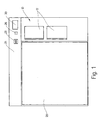
- Fig. 1
- eine Frontansicht eines geschlossenen Leerflaschen-Rücknahmegeräts;
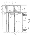
- Fig. 2
- eine Vorderansicht des Leerflaschen-Rücknahmegeräts mit abgenommener Fahrgestellblende;
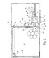
- Fig. 3
- eine Draufsicht auf das Leerflaschen-Rücknahmegerät bei abgenommenem Gehäuseoberteil;
- Fig. 4
- eine Darstellung entsprechend Fig. 3 für ein abgewandeltes Ausführungsbeispiel eines Leerflaschen-Rücknahmegeräts.
- Fig. 1
- a front view of a closed empty bottle return device;
- Fig. 2
- a front view of the empty bottle return device with the chassis panel removed;
- Fig. 3
- a plan view of the empty bottle return device with the upper housing part removed;
- Fig. 4
- a representation corresponding to FIG. 3 for a modified embodiment of an empty bottle return device.
Das in der Zeichnung dargestellte Leerflaschen-Rücknahmegerät
besteht im wesentlichen aus einem Gehäuse 10,
zwei übereinander im Gehäuse angeordneten, an einer
Eingabeöffnung 11 durch je eine Schiebetür 12 verschließbaren
Eingabekammern 14 für aufrecht stehende
Leerflaschen 16, einem in eine nach vorne offene Magazinkammer
18 des Gehäuses einstellbaren Fahrgestell 20
mit zwei übereinander angeordneten Leerflaschenmagazinen
22, sowie einem Bedienungspult 24 mit Bontaste 26,
Bonausgabe 28 und Display 30.The empty bottle return device shown in the drawing
consists essentially of a
Bei dem Ausführungsbeispiel nach Fig. 3 enthalten die
stationären Eingabekammern 14 eine gehäusefeste Stellfläche
32 die nach vorne und hinten durch je eine Einstellschwelle
34 sowie eine rückwärtige Anschlagwand 36
begrenzt ist. Die Stellfläche 32 der Eingabekammern 14
ist über eine Durchtrittsöffnung 38 mit dem benachbarten
Leerflaschenmagazin 22 des Fahrgestells 20 verbunden
und fluchtet mit deren Magazinboden 40. Die Durchtrittsöffnung
38 ist durch den zugleich als Schiebetür
ausgebildeten Ausleger 42 des Sensorschiebers 44 verschließbar.
Ein dem ersten Ausleger 42 gegenüberliegender
Ausleger 46 des Sensorschiebers trägt in der Nähe
seines vorderen Endes mehrere, als optoelektronische
Sendeempfänger ausgebildete Sensoren 48, die zusammen
mit den Spiegeln 50 am Ausleger 42 Reflexionslichtschranken
zur Abtastung der Flaschenkontur bilden. Der
Sensorschieber 44 ist mit Hilfe eines Getriebemotors
52, einem Zahnrad 54 und einer Zahnstange 56 zwischen
einer vorderen, in durchgezogenen Linien dargestellten
Eingabestellung und einer rückwärtigen, in gestrichelten
Linien dargestellten Endstellung horizontal in Richtung
des Doppelpfeils 58 hin- und herverschiebbar. Die
Leerflasche 16 bleibt beim Verschieben des Sensorschiebers
44 auf ihrer Stellfläche 32 in der Eingabekammer
14 stehen. Auf der Verschiebestrecke wandern die Sensoren
48 an der Flasche vorbei und tasten deren Durchmesser
auf verschiedener Höhe über der Stellfläche 32 ab.
Außerdem treibt der Getriebemotor 52 mit seiner Abtriebswelle
60 einen als Zahnrad 62 aus magnetisierbarem Material
und einer Magnetsonde 64 ausgebildeten inkrementellen
Wegaufnehmer an, der im Zusammenwirken mit den
Sensoren 48 zur Flaschenerkennung beiträgt. In der rückwärtigen
Endstellung gibt der Schiebetür-Ausleger 42
des Sensorschiebers 44 die Durchtrittsöffnung 38 frei.
In dieser Endstellung kann die in der Eingabekammer 14
befindliche Leerflasche 16 mit Hilfe des mit einem Motor
66 angetriebenen Querschiebers 68, der den Verschiebeweg
des Sensorsschiebers 44 im Bereich der Eingabekammer
14 kreuzt, durch die Durchtrittsöffnung 38 hindurch
in das Leerflaschenmagazin 22 ausgeschoben werden.3 contain the
stationary input chambers 14 a housing-fixed footprint
32 forward and backward through an
Die Eingabekammer 14 wird bei zurückgezogenem Querschieber
68 im unteren Teil durch den Schieberstempel
116 begrenzt, während sie im oberen Teil entweder durch
eine gehäusefeste oder durch eine sensorschieberfeste
Begrenzungswand begrenzt ist. Erforderlichenfalls sind
im Stempel 116 und in der darüber befindlichen Begrenzungswand
nicht dargestellte Sensorblenden für den
Durchtritt des Sensorlichts ausgespart. The input chamber 14 is when the cross slide is retracted
68 in the lower part by the
Da die auf dem Boden 108 aufstehenden Fahrrollen 110
des Fahrgestells 20 einem allmählichen Verschleiß unterliegen,
müssen Vorkehrungen getroffen werden, die
eine verschleißunabhängige Ausfluchtung zwischen den
Stellflächen 32 der Eingabekammern 14 einerseits und
den Magazinböden 40 des Fahrgestells 20 andererseits
bei in die Magazinkammer 18 eingeschobenem Fahrgestell
20 gewährleisten. Hierzu sind auf der Seite der Eingabekammern
14 in die Magazinkammer 18 eingreifende Stützrollen
112 vorgesehen, auf die das Fahrgestell 20 beim
Einschieben in die Magazinkammer 18 unter Abheben der
eingabekammerseitigen Fahrrollen 110 mit einer Führungsrinne
114 aufläuft.Since the
Das Ausführungsbeispiel nach Fig. 4 unterscheidet sich
von demjenigen nach Fig. 3 vor allem dadurch, daß die
als optoelektronische Sendeempfänger ausgebildeten Sensoren
148 und ihre Spiegel 50 gehäusefest im Bereich
des Verschiebewegs des Querschiebers 68 angeordnet
sind, so daß der Sensorschieber 44 entfällt. Der Querschieber
68 ist mit Hilfe des Getriebemotors 66, einem
Zahnrad 67 und einer Zahnstange 68 zwischen einer rückwärtigen,
in durchgezogenen Linien dargestellten Eingabestellung
und einer vorderen, in gestrichelten Linien
dargestellten Endstellung horizontal in Richtung des
Doppelpfeils 69 hin- und herverschiebbar. Außerdem
treibt der Getriebemotor 66 mit seiner Abtriebswelle
160 eine als Zahnrad 162 aus magnetisierbarem Material
und einer Magnetsonde 164 ausgebildeten inkrementalen
Wegaufnehmer an, der im Zusammenwirken mit den Sensoren
148 zur Flaschenerkennung beiträgt. Der Querschieber
68 weist eine schieberfeste Plattform 120 auf, die als
Stellfläche für die einzustellende Leerflasche 16 dient.
Zur Seite des Antriebsmotors 66 hin ist eine schieberfeste
Begrenzungswand 116 vorgesehen, während die Rückwand
36 der Eingabekammer gehäusefest angeordnet ist.
Die Plattform 120 gelangt mit der auf ihr befindlichen
Flasche 16 über den Verschiebeweg durch die Durchtrittsöffnung
38 hindurch in das Leerflaschenmagazin 22 und
wird entlang dem Verschiebeweg zur Flaschenerkennung
durch die Sensoren 148 berührungslos abgetastet. Die
eigentliche Übergabe der Leerflasche 16 in das Leerflaschenmagazin
22 erfolgt durch einen Abstreifer 124, der
bei ausgefahrenem Querschieber 116 mit Hilfe eines Antriebsmotors
126 über die Plattform 120 hinweg vor die
Durchtrittsöffnung 38 verfahren wird, so daß beim anschließenden
Zurückziehen des Querschiebers 116 die
Leerflasche 16 von der Plattform 120 abgestreift wird.
Der Flaschenabstreifer 124 dient bei diesem Ausführungsbeispiel
zugleich als Verschlußtür für die Durchtrittsöffnung
42. Um bei geöffneter Eingabekammer 14
einen Durchgriff zu den Sensoren 148 und zur Durchtrittsöffnung
38 zu verhindern, ist zusätzlich eine
Trennwand 128 vorgesehen, die starr mit dem Abstreifer
124 verbunden und gemeinsam mit diesem verschiebbar
sein kann.4 differs
3 mainly by the fact that the
sensors designed as
Die Magazinböden 40 weisen einen im wesentlichen rechteckigen
Begrenzungsrand 118 auf, der bei den gezeigten
Ausführungsbeispielen durch die vertikalen Außenwände
des Fahrgestells 20 gebildet ist. Die Durchtrittsöffnungen
38 werden durch je einen Wanddurchbruch im eingabeseitigen
Wandbereich des Fahrgestells 20 gebildet,
die unter der Einwirkung einer nicht dargestellten Feder
beim Herausnehmen des Fahrgestells aus der Magazinkammer
18 selbsttätig geschlossen werden.The
Sobald einer der Magazinböden 40 voll ist, wird über
das durch eine auftreffende Leerflasche 16 betätigte
gehäusefeste Sensorelement 120 die Reflexionslichtschranke
122 oder ein Mikroschalter unter Abgabe eines
"Voll"-Signals ausgelöst und die Schiebetür 12 der betreffenden
Eingabekammer 14 gesperrt. Damit kann nur
noch die andere Eingabekammer 14 mit Leerflaschen beschickt
werden, bis auch deren Leerflaschenmagazin 22
voll ist. Ein Weiterbetrieb ist dann erst wieder möglich,
wenn das Fahrgestell 20 mit den vollen Flaschenmagazinen
22 durch eines mit leeren Magazinen ersetzt
wird. Um eine leichte Manövrierbarkeit zu gewährleisten,
ist das Fahrgestell 20 mit relativ großen Fahrrollen
110 versehen. Zum Entleeren werden die Flaschen
16 zunächst vom oberen Magazinboden 40 von oben her
entnommen und gegebenenfalls in bereitstehende Flaschenkästen
einsortiert. Zum Entleeren des unteren Magazinbodens
40 wird der zuvor entleerte obere Magazinboden
40 beispielsweise an einem Scharniergelenk nach
oben geklappt, um von oben her frei an die betreffenden
Flaschen 16 herankommen zu können.As soon as one of the
Zusammenfassend ist folgendes festzustellen: Die Erfindung
bezieht sich auf ein Leerflaschen-Rücknahmegerät
mit einer Eingabekammer 14 für Leerflaschen 16 und einem
Fahrgestell 20 als Wechselmagazin 22. Um eine einfache
Handhabung beim Beschicken und Entleeren des Wechselmagazins
22 zu gewährleisten, ist das Leerflaschenmagazin
22 über eine quer zur Eingabeöffnung 11 ausgerichtete
verschließbare Durchtrittsöffnung 38 von der
stationären Eingabekammer 14 aus zugänglich. Weiter ist
eine Fördereinrichtung vorgesehen, die einen quer zur
Eingaberichtung durch die Eingabekammer 14 hindurch in
Richtung Durchtrittsöffnung 38 hin- und herverschiebbaren
Querschieber 68 aufweist. Um unabhängig vom Verschleißzustand
der Fahrrollen 110 einen glatten Übergang
zwischen der Eingabekammer 14 und dem fahrgestellseitigen
Magazinboden 40 zu gewährleisten, sind Vorkehrungen
zum Ausfluchten des Magazinbodens mit der Stellfläche
der zugehörigen Eingabekammer bei in die Magazinkammer
eingeschobenem Fahrgestell 20 getroffen.In summary, the following can be stated: The invention
refers to an empty bottle return device
with an input chamber 14 for
Claims (7)
- An empty bottle collector comprising a housing (10), at least one intake chamber (14) for empty bottles (16), which intake chamber is accessible from outside through a closable intake aperture (11), an empty bottle store (22) following the intake chamber (14), a motor-drivable feeding mechanism (68) for the transport of individual empty bottles (16) from the intake chamber (14) into the empty bottle store (22), a mechanism (44, 48; 70, 72) provided in the area of the intake chamber (14) for recognizing the bottles, and a control mechanism (82) preferably reacting to output signals of the bottle-recognizing mechanism for controlling the feeding mechanism (68) and, if desired, a ticket output (28), wherein the intake chamber (14) has a placement surface (32) for receiving an upright positioned empty bottle (16) and the empty bottle store (22) has a store floor (40) provided at the level of the placement surface for receiving upright positioned empty bottles (16), characterized in that the empty bottle store (22) is arranged in a carriage (20), which can be moved into a store chamber (18), wherein guide or support rollers (122) are arranged on the carriage (20) and/or on the housing (10), which rollers are disposed at least on one side on the side of the intake chamber (14), through which rollers the carriage (20) can be lifted from the floor (108) when moving into the store chamber (18) with its rollers (110) to a defined position within the housing (10).
- The empty bottle collector of claim 1, characterized by a guide groove (114) cooperating with the guide and support rollers (112).
- The empty bottle collector according to claim 1 or 2, characterized in that the carriage runs up onto the guide and support rollers (112) disposed in the housing and extending into the store chamber (18) on the side of the intake chambers (14) with a guide groove (114), thereby lifting off the rollers (110) nearest the side of the intake chambers.
- The empty bottle collector according to one of the claims 1 to 3, characterized in that the housing has at least two intake chambers (14) arranged one above the other and each equipped with a sensor slide (44) and/or a transverse slide (68), and the carriage (20) has a corresponding number of empty bottle stores (22) arranged one above the other, wherein the store floors (40) of the empty bottle stores (22) are aligned with the placement surfaces (32) of the associated intake chambers (14) when the carriage (20) is positioned in the store chamber (18).
- The empty bottle collector according to one of the claims 1 to 4, characterized in that the store floors (40) have an essentially rectangular boundary edge preferably formed by vertical carriage walls, and that a preferably housing-fixed sensor element (120) reacting to an empty bottle (16) moved thereon is arranged in the boundary edge area opposite the aperture (38).
- The empty bottle collector according to claim 5, characterized in that the sensor element (120) is designed preferably as a lever pivotal about a vertical axis against the force of a spring, which lever carries a reflector arranged in the beam path of a reflecting light barrier or operates a microswitch.
- The empty bottle collector according to claim 5 or 6, characterized in that the sensor element (120) is arranged in the area of an edge corner of the store floors (40), and that the aperture (38) at its associated boundary edge is arranged shifted off center in direction toward a diagonally opposite boundary edge corner.
Applications Claiming Priority (3)
| Application Number | Priority Date | Filing Date | Title |
|---|---|---|---|
| DE4400251 | 1994-01-07 | ||
| DE4400251 | 1994-01-07 | ||
| EP95904432A EP0738409B1 (en) | 1994-01-07 | 1994-12-07 | Empty bottle collector |
Related Parent Applications (2)
| Application Number | Title | Priority Date | Filing Date |
|---|---|---|---|
| EP95904432A Division EP0738409B1 (en) | 1994-01-07 | 1994-12-07 | Empty bottle collector |
| EP95904432.2 Division | 1995-07-13 |
Publications (3)
| Publication Number | Publication Date |
|---|---|
| EP0802511A2 EP0802511A2 (en) | 1997-10-22 |
| EP0802511A3 EP0802511A3 (en) | 1997-11-19 |
| EP0802511B1 true EP0802511B1 (en) | 2002-04-10 |
Family
ID=6507528
Family Applications (2)
| Application Number | Title | Priority Date | Filing Date |
|---|---|---|---|
| EP97111001A Expired - Lifetime EP0802511B1 (en) | 1994-01-07 | 1994-12-07 | Empty bottle reverse vending device |
| EP95904432A Expired - Lifetime EP0738409B1 (en) | 1994-01-07 | 1994-12-07 | Empty bottle collector |
Family Applications After (1)
| Application Number | Title | Priority Date | Filing Date |
|---|---|---|---|
| EP95904432A Expired - Lifetime EP0738409B1 (en) | 1994-01-07 | 1994-12-07 | Empty bottle collector |
Country Status (10)
| Country | Link |
|---|---|
| US (1) | US5788045A (en) |
| EP (2) | EP0802511B1 (en) |
| JP (1) | JP2997317B2 (en) |
| AT (2) | ATE216109T1 (en) |
| CA (1) | CA2179806A1 (en) |
| DE (3) | DE59405496D1 (en) |
| ES (1) | ES2115354T3 (en) |
| FI (1) | FI962760L (en) |
| NO (1) | NO314864B1 (en) |
| WO (1) | WO1995019020A1 (en) |
Families Citing this family (11)
| Publication number | Priority date | Publication date | Assignee | Title |
|---|---|---|---|---|
| DE19625055B4 (en) * | 1995-09-28 | 2004-11-18 | Hans-Hermann Trautwein Sb-Technik Gmbh | Device and method for measuring the diameter of objects |
| EP0895201A1 (en) * | 1997-07-31 | 1999-02-03 | Sanden Corporation | Empty bottle collecting apparatus having a reduced space for a bottle taking-in portion |
| DE29812678U1 (en) | 1998-07-16 | 1998-10-29 | Kiesel, Alfred, 47259 Duisburg | Return station for reusable containers |
| EP1150257A1 (en) | 2000-04-29 | 2001-10-31 | Prokent AG | Device for automatically collecting empty containers |
| DE10347565B4 (en) * | 2003-10-14 | 2006-08-10 | Wincor Nixdorf International Gmbh | Cleaning system for a reverse vending machine for empty containers, cleaning module and method for operating a reverse vending machine |
| ES2730001T3 (en) * | 2005-01-25 | 2019-11-07 | Tomra Systems Asa | Medium in a reverse vending machine (RVM) for receiving, handling, sorting and storing returnable items or objects |
| US8109378B2 (en) * | 2005-07-14 | 2012-02-07 | Primo Water Corporation | Bottled water distribution method and bottle return apparatus |
| DE102009026557B8 (en) | 2009-05-28 | 2024-04-18 | Sielaff GmbH & Co. KG Automatenbau Herrieden | Empty container return device and method for operating an empty container return device |
| DE102010040177A1 (en) | 2010-09-02 | 2012-03-08 | Sielaff Gmbh & Co. Kg Automatenbau | Reverse vending machine has control device that switches touch screen from article delivery/return mode to maintenance mode when door is in open state |
| DE102016000854A1 (en) * | 2016-01-27 | 2017-07-27 | Interseroh Dienstleistungs Gmbh | Mobile counting and detection device for beverage packaging |
| EP3693652B1 (en) * | 2019-02-07 | 2023-07-12 | CleanTech Swiss AG | Filling station for gas bottles and motor vehicles |
Family Cites Families (8)
| Publication number | Priority date | Publication date | Assignee | Title |
|---|---|---|---|---|
| US4248334A (en) * | 1978-03-13 | 1981-02-03 | Pepsico Inc. | Recycling apparatus |
| DE3320266C2 (en) * | 1983-06-04 | 1986-01-23 | Hans-Hermann 7302 Ostfildern Trautwein | Empty bottle collection and billing device |
| US4519307A (en) * | 1983-12-08 | 1985-05-28 | Aluminum Company Of America | Container recycling apparatus using scanning means to read code markings on containers |
| FR2563926B1 (en) * | 1984-05-04 | 1986-10-10 | Dejoux Andre | MACHINE FOR DISSIGNING EMPTY BOTTLES PICKED UP BY LARGE AREA STORES |
| US5111927A (en) * | 1990-01-05 | 1992-05-12 | Schulze Jr Everett E | Automated recycling machine |
| DE4127238A1 (en) * | 1991-08-17 | 1993-02-18 | Trautwein Sb Technik Gmbh | Empty bottle return appts. pref. with automatic deposit repayment - has contact arm at side of bottle insertion chamber for controlling operation of conveyor for moving bottle to storage chamber |
| DE4214250A1 (en) * | 1992-04-30 | 1993-11-04 | Trautwein Sb Technik Gmbh | EMPTY BOTTLE RECOVERY DEVICE |
| DE4217925C2 (en) * | 1992-05-30 | 1994-10-27 | Peter Koenig | Device for collecting empties bottles and returning deposit |
-
1994
- 1994-12-07 AT AT97111001T patent/ATE216109T1/en not_active IP Right Cessation
- 1994-12-07 ES ES95904432T patent/ES2115354T3/en not_active Expired - Lifetime
- 1994-12-07 DE DE59405496T patent/DE59405496D1/en not_active Expired - Fee Related
- 1994-12-07 FI FI962760A patent/FI962760L/en unknown
- 1994-12-07 EP EP97111001A patent/EP0802511B1/en not_active Expired - Lifetime
- 1994-12-07 DE DE59410102T patent/DE59410102D1/en not_active Expired - Fee Related
- 1994-12-07 JP JP7518293A patent/JP2997317B2/en not_active Expired - Lifetime
- 1994-12-07 EP EP95904432A patent/EP0738409B1/en not_active Expired - Lifetime
- 1994-12-07 AT AT95904432T patent/ATE164248T1/en not_active IP Right Cessation
- 1994-12-07 WO PCT/EP1994/004074 patent/WO1995019020A1/en not_active Ceased
- 1994-12-07 DE DE4443406A patent/DE4443406A1/en not_active Withdrawn
- 1994-12-07 CA CA002179806A patent/CA2179806A1/en not_active Abandoned
- 1994-12-07 US US08/676,183 patent/US5788045A/en not_active Expired - Fee Related
-
1996
- 1996-07-05 NO NO19962851A patent/NO314864B1/en unknown
Also Published As
| Publication number | Publication date |
|---|---|
| DE59410102D1 (en) | 2002-05-16 |
| ES2115354T3 (en) | 1998-06-16 |
| DE59405496D1 (en) | 1998-04-23 |
| JP2997317B2 (en) | 2000-01-11 |
| FI962760A0 (en) | 1996-07-05 |
| FI962760A7 (en) | 1996-07-05 |
| US5788045A (en) | 1998-08-04 |
| NO962851L (en) | 1996-08-22 |
| JPH09507323A (en) | 1997-07-22 |
| EP0802511A2 (en) | 1997-10-22 |
| ATE216109T1 (en) | 2002-04-15 |
| NO962851D0 (en) | 1996-07-05 |
| EP0738409B1 (en) | 1998-03-18 |
| WO1995019020A1 (en) | 1995-07-13 |
| FI962760L (en) | 1996-07-05 |
| CA2179806A1 (en) | 1995-07-13 |
| EP0738409A1 (en) | 1996-10-23 |
| NO314864B1 (en) | 2003-06-02 |
| ATE164248T1 (en) | 1998-04-15 |
| EP0802511A3 (en) | 1997-11-19 |
| DE4443406A1 (en) | 1995-07-13 |
Similar Documents
| Publication | Publication Date | Title |
|---|---|---|
| DE69819527T2 (en) | vending machine | |
| EP0802511B1 (en) | Empty bottle reverse vending device | |
| DE19846791A1 (en) | Cigarette dispensing vending machine, has series of trays each with drive unit and can be selected to deliver packs from front end | |
| DE3630191A1 (en) | DEVICE FOR DISPENSING COIN ROLLS | |
| EP0173119B1 (en) | Coin storage and vending machine | |
| DE2226769A1 (en) | DEVICE FOR STORING AND DISPOSING ITEMS | |
| EP0128373B1 (en) | Collecting and settling device for empty bottles | |
| DE4318388C2 (en) | Empty bottle redemption device | |
| DE1761346B1 (en) | Article container conveyor device | |
| DE102013012763B4 (en) | GOODS MACHINE | |
| DE10130984B4 (en) | Storage and retrieval machine and method for operating a product storage rack, in particular a picking device | |
| DE1802970A1 (en) | Dispensing device with inclined shelves for items or goods that can be shed | |
| DE69408712T2 (en) | Method and device for assembling goods | |
| DE3912971C1 (en) | ||
| DE202004013566U1 (en) | Acceptance device for return machines, in particular for bottle or can-shaped beverage containers | |
| DE9321439U1 (en) | Empty bottle return device | |
| DE4126554A1 (en) | Automatic programmable supply system for goods - uses vacuum entrainment mechanism and conveyor for gentle handling | |
| DE10258069A1 (en) | Empty container returning device, especially for single use, deposit bearing glass or plastic drinks bottles or tins, has a modular input section with a modular transport path for reliable movement of containers to receiving areas | |
| EP0416627A1 (en) | Method and device for storing goods and automatically selecting them from shelves in large scale stores | |
| DE102005006562A1 (en) | Empty container e.g. disposable container, retracting device, has additional or alternative conveying unit arranged adjacent to input unit over rotatable flap in conveying arm and including motor driven conveyor belt with drive plate | |
| AT402394B (en) | AUTOMATIC PICKING COMPLETE SYSTEM | |
| DE10340264A1 (en) | Return and collection unit for empty, deposit containers of different material, i.e. glass, plastic and tin, has a manipulator, material recognition unit and two or more conveying channels for movement of selected packaging items | |
| DE102015222445B3 (en) | Merchandise compartment, vending machine and method for dispensing a product from a goods compartment | |
| DE4429541C1 (en) | Returnable drinking-vessel, esp. beaker identification appts | |
| DE102023126644A1 (en) | Dispensing device for dispensing flat items |
Legal Events
| Date | Code | Title | Description |
|---|---|---|---|
| PUAI | Public reference made under article 153(3) epc to a published international application that has entered the european phase |
Free format text: ORIGINAL CODE: 0009012 |
|
| PUAL | Search report despatched |
Free format text: ORIGINAL CODE: 0009013 |
|
| AC | Divisional application: reference to earlier application |
Ref document number: 738409 Country of ref document: EP |
|
| AK | Designated contracting states |
Kind code of ref document: A2 Designated state(s): AT BE CH DE ES FR GB GR IE IT LI NL SE |
|
| AK | Designated contracting states |
Kind code of ref document: A3 Designated state(s): AT BE CH DE ES FR GB GR IE IT LI NL SE |
|
| 17P | Request for examination filed |
Effective date: 19971016 |
|
| GRAG | Despatch of communication of intention to grant |
Free format text: ORIGINAL CODE: EPIDOS AGRA |
|
| 17Q | First examination report despatched |
Effective date: 20010418 |
|
| GRAG | Despatch of communication of intention to grant |
Free format text: ORIGINAL CODE: EPIDOS AGRA |
|
| GRAG | Despatch of communication of intention to grant |
Free format text: ORIGINAL CODE: EPIDOS AGRA |
|
| GRAH | Despatch of communication of intention to grant a patent |
Free format text: ORIGINAL CODE: EPIDOS IGRA |
|
| GRAH | Despatch of communication of intention to grant a patent |
Free format text: ORIGINAL CODE: EPIDOS IGRA |
|
| REG | Reference to a national code |
Ref country code: GB Ref legal event code: IF02 |
|
| GRAA | (expected) grant |
Free format text: ORIGINAL CODE: 0009210 |
|
| AC | Divisional application: reference to earlier application |
Ref document number: 738409 Country of ref document: EP |
|
| AK | Designated contracting states |
Kind code of ref document: B1 Designated state(s): AT BE CH DE ES FR GB GR IE IT LI NL SE |
|
| PG25 | Lapsed in a contracting state [announced via postgrant information from national office to epo] |
Ref country code: IE Free format text: LAPSE BECAUSE OF FAILURE TO SUBMIT A TRANSLATION OF THE DESCRIPTION OR TO PAY THE FEE WITHIN THE PRESCRIBED TIME-LIMIT Effective date: 20020410 |
|
| REF | Corresponds to: |
Ref document number: 216109 Country of ref document: AT Date of ref document: 20020415 Kind code of ref document: T |
|
| REG | Reference to a national code |
Ref country code: CH Ref legal event code: EP |
|
| REG | Reference to a national code |
Ref country code: IE Ref legal event code: FG4D Free format text: GERMAN |
|
| REF | Corresponds to: |
Ref document number: 59410102 Country of ref document: DE Date of ref document: 20020516 |
|
| GBT | Gb: translation of ep patent filed (gb section 77(6)(a)/1977) |
Effective date: 20020704 |
|
| ET | Fr: translation filed | ||
| REG | Reference to a national code |
Ref country code: GR Ref legal event code: EP Ref document number: 20020402042 Country of ref document: GR |
|
| PG25 | Lapsed in a contracting state [announced via postgrant information from national office to epo] |
Ref country code: ES Free format text: LAPSE BECAUSE OF FAILURE TO SUBMIT A TRANSLATION OF THE DESCRIPTION OR TO PAY THE FEE WITHIN THE PRESCRIBED TIME-LIMIT Effective date: 20021030 |
|
| PG25 | Lapsed in a contracting state [announced via postgrant information from national office to epo] |
Ref country code: GB Free format text: LAPSE BECAUSE OF NON-PAYMENT OF DUE FEES Effective date: 20021207 Ref country code: AT Free format text: LAPSE BECAUSE OF NON-PAYMENT OF DUE FEES Effective date: 20021207 |
|
| PG25 | Lapsed in a contracting state [announced via postgrant information from national office to epo] |
Ref country code: SE Free format text: LAPSE BECAUSE OF NON-PAYMENT OF DUE FEES Effective date: 20021208 |
|
| REG | Reference to a national code |
Ref country code: IE Ref legal event code: FD4D Ref document number: 0802511E Country of ref document: IE |
|
| PG25 | Lapsed in a contracting state [announced via postgrant information from national office to epo] |
Ref country code: LI Free format text: LAPSE BECAUSE OF NON-PAYMENT OF DUE FEES Effective date: 20021231 Ref country code: CH Free format text: LAPSE BECAUSE OF NON-PAYMENT OF DUE FEES Effective date: 20021231 Ref country code: BE Free format text: LAPSE BECAUSE OF NON-PAYMENT OF DUE FEES Effective date: 20021231 |
|
| PLBE | No opposition filed within time limit |
Free format text: ORIGINAL CODE: 0009261 |
|
| STAA | Information on the status of an ep patent application or granted ep patent |
Free format text: STATUS: NO OPPOSITION FILED WITHIN TIME LIMIT |
|
| 26N | No opposition filed |
Effective date: 20030113 |
|
| BERE | Be: lapsed |
Owner name: *HANS-HERMANN TRAUTWEIN SB-TECHNIK G.M.B.H. Effective date: 20021231 |
|
| PG25 | Lapsed in a contracting state [announced via postgrant information from national office to epo] |
Ref country code: NL Free format text: LAPSE BECAUSE OF NON-PAYMENT OF DUE FEES Effective date: 20030701 |
|
| EUG | Se: european patent has lapsed | ||
| GBPC | Gb: european patent ceased through non-payment of renewal fee | ||
| REG | Reference to a national code |
Ref country code: CH Ref legal event code: PL |
|
| NLV4 | Nl: lapsed or anulled due to non-payment of the annual fee |
Effective date: 20030701 |
|
| PG25 | Lapsed in a contracting state [announced via postgrant information from national office to epo] |
Ref country code: FR Free format text: LAPSE BECAUSE OF NON-PAYMENT OF DUE FEES Effective date: 20030901 |
|
| REG | Reference to a national code |
Ref country code: FR Ref legal event code: ST |
|
| PG25 | Lapsed in a contracting state [announced via postgrant information from national office to epo] |
Ref country code: GR Free format text: LAPSE BECAUSE OF NON-PAYMENT OF DUE FEES Effective date: 20040705 |
|
| PG25 | Lapsed in a contracting state [announced via postgrant information from national office to epo] |
Ref country code: IT Free format text: LAPSE BECAUSE OF NON-PAYMENT OF DUE FEES;WARNING: LAPSES OF ITALIAN PATENTS WITH EFFECTIVE DATE BEFORE 2007 MAY HAVE OCCURRED AT ANY TIME BEFORE 2007. THE CORRECT EFFECTIVE DATE MAY BE DIFFERENT FROM THE ONE RECORDED. Effective date: 20051207 |
|
| PGFP | Annual fee paid to national office [announced via postgrant information from national office to epo] |
Ref country code: DE Payment date: 20051222 Year of fee payment: 12 |
|
| PG25 | Lapsed in a contracting state [announced via postgrant information from national office to epo] |
Ref country code: DE Free format text: LAPSE BECAUSE OF NON-PAYMENT OF DUE FEES Effective date: 20070703 |
|
| PG25 | Lapsed in a contracting state [announced via postgrant information from national office to epo] |
Ref country code: GR Free format text: LAPSE BECAUSE OF NON-PAYMENT OF DUE FEES Effective date: 20020410 |