EP0715227B1 - Entwicklungsgerät - Google Patents
Entwicklungsgerät Download PDFInfo
- Publication number
- EP0715227B1 EP0715227B1 EP96200413A EP96200413A EP0715227B1 EP 0715227 B1 EP0715227 B1 EP 0715227B1 EP 96200413 A EP96200413 A EP 96200413A EP 96200413 A EP96200413 A EP 96200413A EP 0715227 B1 EP0715227 B1 EP 0715227B1
- Authority
- EP
- European Patent Office
- Prior art keywords
- developer
- magnetic
- developer carrying
- developing
- carrying member
- Prior art date
- Legal status (The legal status is an assumption and is not a legal conclusion. Google has not performed a legal analysis and makes no representation as to the accuracy of the status listed.)
- Expired - Lifetime
Links
- 230000005291 magnetic effect Effects 0.000 claims description 193
- 239000002245 particle Substances 0.000 claims description 62
- 238000007789 sealing Methods 0.000 claims description 26
- 239000000463 material Substances 0.000 claims description 20
- 239000006249 magnetic particle Substances 0.000 claims description 10
- 239000011230 binding agent Substances 0.000 claims description 8
- 229920005989 resin Polymers 0.000 claims description 8
- 239000011347 resin Substances 0.000 claims description 8
- 230000005684 electric field Effects 0.000 claims description 6
- 229920001225 polyester resin Polymers 0.000 claims description 6
- 239000004645 polyester resin Substances 0.000 claims description 6
- 230000003746 surface roughness Effects 0.000 claims description 5
- 239000003302 ferromagnetic material Substances 0.000 claims description 2
- 230000001105 regulatory effect Effects 0.000 description 16
- 238000005054 agglomeration Methods 0.000 description 13
- 230000002776 aggregation Effects 0.000 description 13
- 230000000694 effects Effects 0.000 description 13
- 238000009826 distribution Methods 0.000 description 9
- 230000007547 defect Effects 0.000 description 6
- 230000003287 optical effect Effects 0.000 description 6
- 230000001846 repelling effect Effects 0.000 description 6
- 230000015572 biosynthetic process Effects 0.000 description 5
- 230000002093 peripheral effect Effects 0.000 description 5
- 239000010935 stainless steel Substances 0.000 description 5
- 229910001220 stainless steel Inorganic materials 0.000 description 5
- 229910000831 Steel Inorganic materials 0.000 description 4
- 239000003086 colorant Substances 0.000 description 4
- 239000000696 magnetic material Substances 0.000 description 4
- 239000010959 steel Substances 0.000 description 4
- 238000004140 cleaning Methods 0.000 description 3
- 239000008151 electrolyte solution Substances 0.000 description 3
- 238000002474 experimental method Methods 0.000 description 3
- 230000004907 flux Effects 0.000 description 3
- 239000000203 mixture Substances 0.000 description 3
- 229920000728 polyester Polymers 0.000 description 3
- 230000003405 preventing effect Effects 0.000 description 3
- 238000000926 separation method Methods 0.000 description 3
- 229910000859 α-Fe Inorganic materials 0.000 description 3
- PXHVJJICTQNCMI-UHFFFAOYSA-N Nickel Chemical compound [Ni] PXHVJJICTQNCMI-UHFFFAOYSA-N 0.000 description 2
- 241000519995 Stachys sylvatica Species 0.000 description 2
- PPBRXRYQALVLMV-UHFFFAOYSA-N Styrene Chemical compound C=CC1=CC=CC=C1 PPBRXRYQALVLMV-UHFFFAOYSA-N 0.000 description 2
- XAGFODPZIPBFFR-UHFFFAOYSA-N aluminium Chemical compound [Al] XAGFODPZIPBFFR-UHFFFAOYSA-N 0.000 description 2
- 229910052782 aluminium Inorganic materials 0.000 description 2
- 230000001276 controlling effect Effects 0.000 description 2
- 230000008021 deposition Effects 0.000 description 2
- 230000006866 deterioration Effects 0.000 description 2
- 238000000034 method Methods 0.000 description 2
- -1 polyethylene terephthalate Polymers 0.000 description 2
- 230000002265 prevention Effects 0.000 description 2
- 230000008569 process Effects 0.000 description 2
- 230000000717 retained effect Effects 0.000 description 2
- 239000007787 solid Substances 0.000 description 2
- 239000000243 solution Substances 0.000 description 2
- 238000011144 upstream manufacturing Methods 0.000 description 2
- VEXZGXHMUGYJMC-UHFFFAOYSA-M Chloride anion Chemical compound [Cl-] VEXZGXHMUGYJMC-UHFFFAOYSA-M 0.000 description 1
- 244000137852 Petrea volubilis Species 0.000 description 1
- VYPSYNLAJGMNEJ-UHFFFAOYSA-N Silicium dioxide Chemical compound O=[Si]=O VYPSYNLAJGMNEJ-UHFFFAOYSA-N 0.000 description 1
- KEAYESYHFKHZAL-UHFFFAOYSA-N Sodium Chemical compound [Na] KEAYESYHFKHZAL-UHFFFAOYSA-N 0.000 description 1
- 229920006311 Urethane elastomer Polymers 0.000 description 1
- 230000009471 action Effects 0.000 description 1
- 239000000654 additive Substances 0.000 description 1
- 230000002411 adverse Effects 0.000 description 1
- 229910045601 alloy Inorganic materials 0.000 description 1
- 239000000956 alloy Substances 0.000 description 1
- 239000003795 chemical substances by application Substances 0.000 description 1
- 229920006026 co-polymeric resin Polymers 0.000 description 1
- 239000011248 coating agent Substances 0.000 description 1
- 238000000576 coating method Methods 0.000 description 1
- 229910017052 cobalt Inorganic materials 0.000 description 1
- 239000010941 cobalt Substances 0.000 description 1
- GUTLYIVDDKVIGB-UHFFFAOYSA-N cobalt atom Chemical compound [Co] GUTLYIVDDKVIGB-UHFFFAOYSA-N 0.000 description 1
- 239000008119 colloidal silica Substances 0.000 description 1
- 239000012141 concentrate Substances 0.000 description 1
- 230000007423 decrease Effects 0.000 description 1
- 230000002542 deteriorative effect Effects 0.000 description 1
- 238000007599 discharging Methods 0.000 description 1
- 239000002270 dispersing agent Substances 0.000 description 1
- 229920001971 elastomer Polymers 0.000 description 1
- 239000010419 fine particle Substances 0.000 description 1
- 239000011521 glass Substances 0.000 description 1
- 230000002209 hydrophobic effect Effects 0.000 description 1
- 230000006872 improvement Effects 0.000 description 1
- 239000006247 magnetic powder Substances 0.000 description 1
- 230000005415 magnetization Effects 0.000 description 1
- 238000004519 manufacturing process Methods 0.000 description 1
- 238000002844 melting Methods 0.000 description 1
- 230000008018 melting Effects 0.000 description 1
- 238000002156 mixing Methods 0.000 description 1
- 229910052759 nickel Inorganic materials 0.000 description 1
- 239000004745 nonwoven fabric Substances 0.000 description 1
- 230000035699 permeability Effects 0.000 description 1
- 239000004033 plastic Substances 0.000 description 1
- 229920003023 plastic Polymers 0.000 description 1
- 229920000139 polyethylene terephthalate Polymers 0.000 description 1
- 239000005020 polyethylene terephthalate Substances 0.000 description 1
- 238000011112 process operation Methods 0.000 description 1
- 230000005855 radiation Effects 0.000 description 1
- 239000000523 sample Substances 0.000 description 1
- 238000005488 sandblasting Methods 0.000 description 1
- 238000003756 stirring Methods 0.000 description 1
- 229920001909 styrene-acrylic polymer Polymers 0.000 description 1
- 239000004094 surface-active agent Substances 0.000 description 1
- 210000002105 tongue Anatomy 0.000 description 1
Images


Classifications
-
- G—PHYSICS
- G03—PHOTOGRAPHY; CINEMATOGRAPHY; ANALOGOUS TECHNIQUES USING WAVES OTHER THAN OPTICAL WAVES; ELECTROGRAPHY; HOLOGRAPHY
- G03G—ELECTROGRAPHY; ELECTROPHOTOGRAPHY; MAGNETOGRAPHY
- G03G15/00—Apparatus for electrographic processes using a charge pattern
- G03G15/06—Apparatus for electrographic processes using a charge pattern for developing
- G03G15/08—Apparatus for electrographic processes using a charge pattern for developing using a solid developer, e.g. powder developer
- G03G15/09—Apparatus for electrographic processes using a charge pattern for developing using a solid developer, e.g. powder developer using magnetic brush
- G03G15/0921—Details concerning the magnetic brush roller structure, e.g. magnet configuration
- G03G15/0928—Details concerning the magnetic brush roller structure, e.g. magnet configuration relating to the shell, e.g. structure, composition
-
- G—PHYSICS
- G03—PHOTOGRAPHY; CINEMATOGRAPHY; ANALOGOUS TECHNIQUES USING WAVES OTHER THAN OPTICAL WAVES; ELECTROGRAPHY; HOLOGRAPHY
- G03G—ELECTROGRAPHY; ELECTROPHOTOGRAPHY; MAGNETOGRAPHY
- G03G15/00—Apparatus for electrographic processes using a charge pattern
- G03G15/06—Apparatus for electrographic processes using a charge pattern for developing
- G03G15/08—Apparatus for electrographic processes using a charge pattern for developing using a solid developer, e.g. powder developer
- G03G15/09—Apparatus for electrographic processes using a charge pattern for developing using a solid developer, e.g. powder developer using magnetic brush
- G03G15/0942—Apparatus for electrographic processes using a charge pattern for developing using a solid developer, e.g. powder developer using magnetic brush with means for preventing toner scattering from the magnetic brush, e.g. magnetic seals
Definitions
- the present invention relates to a developing apparatus for developing an electrostatic latent image formed on an image bearing member through an electrophotographic process or an electrostatic recording process, more particularly to a developing apparatus using a one component developer containing as a major component magnetic toner particles and a two component developer containing magnetic carrier particles and toner particles.
- U.S. Patent No. 4,387,664 and European Patent Application 0,219,233A disclose that a magnetic member is disposed extending along the length of a developer carrier member at a developer layer thickness regulating portion in the outlet of the developer where a developer carrying member displaces the developer from the container toward a developing station.
- the magnetic member is disposed in a magnetic field provided by a magnet contained within the developer carrying member to regulate the thickness of the developer layer.
- U.S. Patents Nos. 4,563,978 and 4,838,200, and European Patent Application No. 0,219,233A disclose a developing apparatus including a magnetic member length of the developer carrying member at an inlet for the developer where the developer carrying member returns into the container the developer having passed through the developing station.
- the magnetic member is also disposed within the magnetic field of the magnet within the developer carrying member to prevent the developer from flowing out through the inlet to the outside.
- U.S. Patents Nos. 4,341,179 and 4,373,468 disclose means for preventing the developer from leaking out from the longitudinal ends of the developer carrying member.
- sealing members 14 made of mode plane or non-woven fabric at the opposite longitudinal ends of the developer carrying member 10b.
- an elastic sealing members 16 having elastic contact tongues 16a for assuring the contact thereof with the developer carrying member 10b are contacted to the longitudinal opposite ends of the developer carrying member 10b. Using such end sealing members, the developer is prevented from leaking out of the container beyond the longitudinal ends of the developer carrying member, or the developer from being introduced into the bearings 12 of the developer carrying member.
- the developer can go into the contact portion between the end seal members 14 and 16 and the developer carrying member 10b although the amount thereof is small. Therefore. when the developing apparatus is operated for a long period. the developer is rubbed by the press-contact portion with the result of agglomeration of the developer.
- a part of the agglomeration is taken into the other developer, but in the case where the agglomeration is large, it is blocked by the developer layer thickness regulating blade with the result of occurrence of the developer non-application portion on the developer carrying member 10b, by which a white stripe appears on the resultant image.
- the agglomeration of the developer is a significant problem from the standpoint of further improvement in the image quality. This is because in the color image, subtle colors are represented by overlaying plural color toners, and therefore, if the above-described defect is involved in one of the color images, the resultant image involves the defect which is remarkable.
- US-A-4213617 discloses a developing station including a seal comprising a magnetic ring and a magnet for establishment of a magnetic brush at end portions of a developer carrying member.
- the seal serves to prevent developer from escaping in the axial direction.
- JP-U-62-143968 is similar.
- Embodiments of the invention subject the developer to reduced stress by the end sealing members and by the developer carrier member and thereby reduce or prevent developer at moderation and fusing.
- Embodiments of the invention enable leakage of the developer from the longitudinal ends of the developer carrying member to be effectively prevented without significantly increasing the load required to drive the developer carrier member. Because agglomeration of the developer attributable to the provision of the sealing members is reduced or prevented, in embodiments of the invention the quality of the image is improved and images of high resolution can be obtained.
- embodiments of the invention can provide developing apparatus which is suitable for the production of high quality colour images.
- Figure 1 is a partly sectional view of a part of a conventional developing apparatus.
- Figure 2 is a partly sectional view of a conventional developing apparatus.
- Figure 3 is a sectional view of a color copying apparatus to which the present invention is applicable.
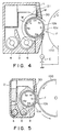
- Figure 4 is a sectional view of a developing apparatus according to an embodiment of the present invention.
- Figure 5 is a sectional view of the developing apparatus illustrating behavior of the developer.
- Figure 6 is a partly sectional view of a longitudinal end portion of the developing sleeve in a developing apparatus according to an embodiment of the present invention.
- Figure 7 illustrates magnetic brush formed adjacent a longitudinal end of the developing sleeve.
- Figure 8 is a partly sectional view of a part of the developing apparatus according to an embodiment of the present invention.
- Figure 9 is a partly sectional view of a developing apparatus according to a further embodiment of the present invention.
- Figure 10 is a partly sectional view of a developing apparatus according to a yet further embodiment of the present invention.
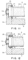
- Figure 11 is a partly sectional view of a part of a developing apparatus according to a further embodiment of the present invention.
- Figure 12 is a partly sectional view of a part of a developing apparatus according to a further embodiment of the present invention.
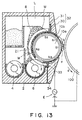
- Figure 13 is a cross-sectional view of a developing apparatus according to a further embodiment of the present invention.
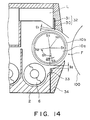
- Figure 14 is a cross-sectional view of a part of the developing apparatus of Figure 13.
- a full-color electrophotographic copying apparatus to which the present invention is applicable.
- a photosensitive drum 100 functioning as an image bearing member and having a surface electrophotographic photosensitive layer. It is rotatable in the direction indicated by an arrow x direction (counterclockwise direction).
- a primary charger A is disposed: to the left of the photosensitive drum 100, a rotary type developing device B is disposed; below the photosensitive drum 100, a transfer device 5 is disposed; and to the light of the photosensitive drum 1, a cleaning device C is disposed.
- the optical system D which functions to project an image of an original O on a transparent platen 7 (glass or the like) onto the photosensitive drum 100 (through a slit) at an exposure station 3 disposed between the primary charger A and the rotary developing device 100
- the optical system D may be of any known type.
- it comprises a first scanning mirror 11, second and third scanning mirrors 12 and 13 movable in the same direction as the first scanning mirror 11 and at a speed which is one half that of the first scanning mirror 11. Since such an optical system D constitutes a known slit exposure optical system, and therefore. the detailed description thereof is omitted for simplicity.
- the original illuminating light source 10 is movable together with the first scanning mirror 11, and a color separation filter 17 is disposed between a fourth fixed mirror 15 and the exposure station 3.
- the color separation filter 17 includes red, green, blue and ND filters are selectively introduced into the optical path.
- the light image by the light reflected by the original O scanned by the first. second and third mirrors 11. 12 and 13 is passed through a lens 14, and is reflected by the fourth fixed mirror 15, and is color-separated by a color separation filter 17. It is imaged on the photosensitive drum 100 at the exposure station.
- an image fixing device I At the right portion in the full-color electrophotographic copying apparatus, there are an image fixing device I and a sheet feeding device 10. Between the image transfer device 5 and the fixing device I and the sheet feeding device J. there are transfer material conveying systems 25 and 35.
- the photosensitive drum 100 is subjected to charging. image exposure. developing, transferring and cleaning operations (image forming process operations) by the primary charger A, the optical system D, the rotary developing device B. the transfer device 5 and the cleaning device C, for each of the separated colors.
- the rotary developing device B includes a rotatable supporting member 300 and developing units supported on the supporting member 300 at 90 degrees intervals.
- the supporting member 300 supports four developing units. more particularly. a developing unit 101Y containing yellow toner, a developing unit 101M containing a magenta toner. a developing unit 101C containing cyan toner and a developing unit 101BK containing black toner. An electrostatic latent image corresponding to each of the colors formed on the surface of the photosensitive drum 100 is visualized with the developer contained in the corresponding developing unit.
- the developing sleeve of a desired developing unit is presented to the predetermined developing position where it is faced to the photosensitive drum 100 to permit developing action by the developing unit.
- the developing sleeve is supplied with a developing bias voltage which is a vibratory voltage such as an AC voltage or a substantially DC biased AC voltage provided by the voltage source E ( Figure 4) so that an altemating or vibratory electric field is formed at the developing position, by which the toner is repeatedly transferred to the photosensitive drum or transferred back to the developing sleeve to finally develop the latent image.
- the waveform of the bias voltage may be sine wave, rectangular wave, triangular wave or the like.
- the black developing unit 101BK is presented to the photosensitive drum 100.
- the developing device may be of a regular development type wherein a dark potential portion of the latent image receives the toner or a reverse-development wherein a light potential portion of the latent image receives the toner.
- a reverse-development type When the reverse-development type is used, the portion of the photosensitive member to receive the toner is exposed to laser beam modulated in accordance with an image signal or LED radiation or the like.
- the visualized image thus provided is transferred onto a transfer material P such as a sheet of paper supplied from the sheet feeding device J, at the image transfer station.
- the transfer device 5 is provided with a transfer drum 5b having a gripper 5a for gripping and retaining the transfer material P on the periphery of the transfer drum 5b.
- the gripper 5a of the transfer drum 5b grips the leading edge of the transfer material P supplied from the transfer material cassette 31 or 32 of the feeding device J through the transfer material conveying system 35. and the transfer drum 5b rotates, carrying the transfer material P to transfer the visualized (toner) color images from the photosensitive drum 100.
- the transfer material P receives the color visualized images sequentially and superposedly, and is released from the gripper 5a and is separated from the transfer drum 5b by a separating pawl. Then. the transfer material P is conveyed by the transfer material conveying system 25 to an image fixing device I, by which the toner image on the transfer material P is heated, fused and fixed on the transfer material P. Thereafter, the transfer material P is discharged to a tray K.
- Figure 4 is a sectional view of one of the developing units shown in Figure 3.
- the image bearing member 100 photosensitive drum
- a developing sleeve 10b is faced to the photosensitive drum 100 at the developing position. It is made of non-magnetic material such as aluminum. stainless steel (SUS 316).
- Substantially left half circumferential surface of the developing sleeve 12 is placed in a developer container 2 through a longitudinal opening thereof. The substantially right half thereof is exposed outside the container 2. It is rotatably supported and is driven to rotate in a direction b.
- a stationary permanent magnet is provided to produce a stationary magnetic field.
- the magnet 10a maintains its position and pose.
- the magnet 10a has five magnetic poles ("N" indicates N-polarity; and "S” indicates S-polarity).
- the magnet 10A is not limitedly a permanent magnet, but may be an electromagnet.
- a developer layer regulating member in the form of a non-magnetic blade 30 is fixed on a wall of the container 2 at its base portion, and the leading edge of the blade 30 is disposed spaced apart from the developing sleeve 10b with a small clearance along the length of the sleeve.
- the non-magnetic blade 30 is made of SUS 316, for example.
- a developer guiding member L has a surface closely disposed to a side of the non-magnetic blade 30 and has a bottom surface functioning as a developer guiding surface M.
- a developer layer thickness regulating portion is constituted by the non-magnetic blade 30, the developer guiding member L or the like.
- the regulating station regulates the thickness of a layer of the developer discharged from the container 2 and carried to the developing station F.
- the thickness of the developer layer on the sleeve 10b is preferably small such that the developer layer is in contact with the drum 100 at the developing station F where the toner is applied from the sleeve 10b to the drum 100.
- the developer layer is preferably regulated into such a thickness that it is not contacted to the drum 100 at the developing station F.
- the developing device is provided with a developer container 2 for containing a developer 8 which may be a one component magnetic developer containing magnetic toner particles each of which is a mixture of a magnetic particle and resin or may be a two component developer which is a mixture of magnetic carrier particles containing as a major component magnetic particles and toner particles.
- a developer 8 which may be a one component magnetic developer containing magnetic toner particles each of which is a mixture of a magnetic particle and resin or may be a two component developer which is a mixture of magnetic carrier particles containing as a major component magnetic particles and toner particles.
- the developer container 2 there are screws 4 and 6 for reciprocating, circulating and stirring the developer within the developer container 2.
- the developer is omitted for the sake of simplicity.
- the developer used for the color image forming apparatus described above is preferably the two component developer containing the non-magnetic toner particles and the magnetic carrier particles.
- the developing sleeve 10b is provided with a shaft projecting outwardly from longitudinal opposite ends thereof (only one end is shown in Figure 6).
- the shaft is rotatably supported on the side wall 2a of the developer container 2 by bearings 12.
- the sleeve 10b is rotationally driven by a motor through an unshown gear train.
- a magnetic pole S1 functions as a main developing magnetic pole, and is effective to erect chains of the developer particles by its magnetic field.
- the chains of the developer develops the electrostatic latent image on the image bearing member 100.
- the repelling magnetic field formed by the cooperation of the same polarity N3 and N2 poles the developer having the development hysteresis on the developing sleeve 10b fall into the developing container 2.
- the developer is sufficiently stirred by the screw 6, it is supplied to the sleeve again.
- the behavior of the developer 8 is shown in Figure 5.
- a plate-like magnetic member 21 is disposed to enclose such a portion of the developing sleeve 10b as is within the container 2, and is mounted on a side wall 2a of the developer container 2.
- the plate-like magnetic member 21 is provided at each of the longitudinal ends of the sleeve 10b, extending along the circumferential direction of the sleeve 10b with a small clearance from the sleeve 10b.
- the magnetic member 21 is within the influence of the magnetic field provided by the magnet 10a. In Figure 6, for example, only one longitudinal end of the sleeve 10b is shown.
- the magnetic member 21 is preferably made of ferromagnetic material such as steel, nickel, cobalt or an alloy of two or more of them, having a thickness (t) of 0.2 - 1 mm. These materials have (1/2)(BH)max of not more than 0.7 J/m 3 , where (BH)max is the maximum of B x H, where B is residual magnetic flux density, and H is coercive force, wherein (BH)max is a maximum energy multiple.
- the gap g from the developing sleeve 10b is not limited, but may be properly selected within the range of 0.3 - 2 mm.
- the magnetic member 21 has a part annular configuration concentric with the developing sleeve 10b and having a width w to provide a uniform gap G from the developing sleeve 10b.
- the configuration is not limited to this, but may be determined properly by one skilled in the art.
- the magnetic plate 21 extends along the periphery of the developing sleeve 10b without contact thereto.
- An angle formed between a side surface of the magnetic plate 21 and a line perpendicular to the circumferential surface of the developing sleeve 10b is not more than 45 degrees in order to assure prevention of the leakage of the developer.
- the magnetic plate 21 extends covering the entire circumferential surface of the developing sleeve 10b, but it is not inevitable. As shown in Figure 4, it may cover a part of the entire circumferential surface of the developing sleeve 10b.
- the magnetic plates 21 is magnetized by the magnetic force of the magnetic roller 10a in the developing sleeve 10b, so that a magnetic circuit is established between the magnetic roller 10a and the magnetic plates 21. This is effective to concentrate the magnetic field to the free edge of the magnetic plate 21 adjacent to the developing sleeve 10b. Therefore, as shown in Figure 7, a high density magnetic brush m of the developer particles is formed in the gap g between the magnetic plate 21 and the developing sleeve 10b.
- the magnetic brush m functions to prevent the developer from leaking along the developing sleeve 10b through the clearance between the developer container side wall 2a and the developing sleeve 10b surface into the bearing 12 and to prevent the developer from scattering externally.
- the magnetic brush m of the developer formed in the gap g between the magnetic plate and the developing sleeve 10b functions as an end seal (where the developer is the two component developer, the brush m is a magnetic brush of the magnetic carrier particles; and where it is a one component developer, the magnetic brush m is the brush of the magnetic toner).
- an auxiliary sealing member 23 is disposed adjacent to the magnetic plate 21.
- the auxiliary sealing member 23 is made of an elastic sheet having an inside edge resiliently contacted to the developing sleeve 10b at a position between the magnetic plate 21 and the bearing 12, while the elastic sheet being bent.
- a preferable example of the auxiliary sealing member 23 is made of polyethylene terephthalate, urethane rubber sheet or the like having a thickness of 0.1 - 0.5 mm, for example.
- the number and arrangement of the magnetic poles of the magnet roller 10a are not limited to those shown in Figure 4. If the number and arrangement of Figure 4 are used, the formation of the magnetic brush of the developer is not so strong in the portion of the gap g adjacent to the portion where the repelling magnetic field is formed by the poles N3 and N2 as the other portions. Therefore, if the developer moves toward the bearing 12 through the portion of the gap g, the developer is caught by a magnet 25 which is an alternative of the auxiliary sealing member.
- the magnet 25 is a part annular permanent magnet extending along the peripheral surface of the developing sleeve 10b in the region where the magnetic plate 21 exists. at a longitudinal position between the magnetic plate 21 and the bearing 12.
- the part annular magnet may be a rubber magnet containing magnetic powder dispersed therein or a plastic magnet or the like.
- the inside surface of the part annular magnet is magnetized to S polarity. and the outer surface side is magnetized to N polarity. It is particularly effective to prevent the leakage of the developer through the region where the repelling magnetic field is formed by the magnetic poles N3 and N2.
- the developer once caught by the magnet 25 is formed into a magnetic brush in the gap between the magnet 25 and the developing sleeve 10b surface, and thereafter, the magnetic brush functions to seal the developer against the possible leakage in the region where the repelling magnetic field is formed by the magnetic poles N3 and N2.
- the weight average particle size of the magnetic carrier particles in the two component developer usable with the developing apparatus according to the present invention is 30 - 100 microns. Preferably, however, it is 35 - 65 microns. and further preferably it is 40 - 65 microns.
- the weight distribution is preferably such that the component of particle size of not more than 26 microns is not more than 2 - 6 %. that the component of the particle size of 35 - 43 microns is 5 - 25 % and that the component of the particle size not less than 74 microns is not more than 2 %.
- the electric resistance of the carrier is not less than 50 7 ohm.cm, preferably not less than 10 8 ohm.cm, and further preferably 10 9 - 10 12 ohm.cm, and is preferably provided by coating ferrite particles (maximum magnetization) 60 emu/g coated with resin material.
- the resistance of the magnetic particle for example ferrite particles or ferrite particles coated with resin material is measured using a sandwich type cell having a measuring electrode area of 4 cm 2 and a clearance of 0.4 cm between electrodes. wherein the weight of 1 kg is applied on one of the electrodes. A voltage E (V/cm) is applied across the electrodes, and the resistance of the magnetic particles is obtained on the basis of the current through the circuit containing the electrodes.
- the preferable toner used in this embodiment satisfy that more than 90 % by volume toner particles are within the range of (1/2)M ⁇ r ⁇ (3/2)M, where M is a volume average particle size, and r is a particle size of a toner particle: and that more than 99 % by volume is within the range of 0 ⁇ r ⁇ 2M.
- the volume average particle size M is preferably not more than 10 microns and not less than 4 microns (for the purpose of higher resolution image formation, preferably not more than 10 microns, and further preferably not more than 8 microns).
- volume distribution and the volume average particle size of the toner are measured in the following manner:
- the measuring device is Callter Counter TA-II (available from Callter) to which an interface (Nikkaki) and CX-i Personal Computer (available from Canon Kabushiki Kaisha. Japan) for outputting number average distribution and volume average distribution.
- a first class natrium chloride is used to prepare 1 % NaCI solution.
- the electrolytic solution (100 - 150 ml) is added with 0.1 - 5 ml of surface active agent (dispersing agent) (preferably alkylbenzene sulfonate) and further added with 0.5 - 50 mg of the material to be measured.
- the electrolytic solution suspending the material is subjected to the dispersing operation approximately 1 - 3 min. using an ultrasonic dispersing device.
- the particle size distribution for the particles having the particle size of 20 - 40 microns, and the volume distribution is obtained therefrom. From the volume distribution, the volume average particle size of the sample material can be obtained.
- the image quality improving effect can not be sufficiently expected even if the average particle size is changed when the toner particles having larger particle sizes increase, it is difficult to remove the image roughness at the portion where the image density is low because the large size toner particles contributable to the scattering of the toner are present at the time of the image transfer, however, the average particle size of the toner is reduced.
- the toner particles having the smaller particle size includes the toner particles stuck to the magnetic particles includes, and therefore, the magnetic particles becomes unable to apply the triboelectric charge efficiently to the toner with the result of increased toner scattering or the foggy background.
- the toner particles having small particle size tends to be fused, and therefore, they are fused on the magnetic particles (carrier) with the result of the foggy background and the toner scattering attributable to the carrier deterioration. For the reasons described above, the sharp volume distribution is desired.
- the toner contains binder resin, coloring agent and additives such as electrification controlling agent as desired. It is preferable that hydrophobic colloidal silica fine particles are added to the toner.
- binder resin materials are styrene-acrylic acid-ester resin, styrene-methacryl acid-ester resin or other styrene copolymer or polyester resin.
- the polyester resin is preferable since it provides a sharp fusing property.
- the binder of which was polyester resin When the small particle size toner having the volume average particle size of not more than 10 microns, the binder of which was polyester resin was used, it had the sharp fusing property, but on the other hand, it was so soft that it was easily agglomerated and fused into a mass with slight stress. In addition, the agglomeration was strong because the particle size was small.
- the AC electric field application at the developing station for the purpose of increasing the developing power the good images without remarkable white spots or white stripes were produced from the start of the operation for a long period (more specifically, several hundreds thousands copies on A4 size sheets).
- the developer containing the toner having the particle size around 10 microns were so influenced by the surface roughness that the toner conveying power is steeply increased.
- the portion A of the sleeve carrying the developer to be supplied to the image formation region of the photosensitive member is sand-blasted to provide the surface roughness Rz of not less than 1.5 microns and not more than 5.0 microns in order to increase the developer conveying power under any ambient condition.
- the sandblasting treatment it may be treated by sand paper or the like (U.S. Patent Nos. 4,377,332 and 4.380.966).
- the sealing effect by the magnetic brush at the end portions is desired. it is not preferable that the developer is moved strongly by the conveying force provided by the developer carrying member at the free ends of the magnetic brush formed by the magnetic plate 21. This is because the end sealing effect is reduced by the strong movement of the developer at the free ends of the magnetic brush adjacent the longitudinal ends of the sleeve. and because the strong movement of the developer separates the toner and the carrier with the result of easily toner scattering.
- the toner having a sharp fusing property using the polyester resin as the binder moves strongly together with the carrier at the same portion adjacent to the ends of the magnetic brush for a long period of time. When the separated toner increases, the toner becomes easily agglomerated around the separated toner. Then, the non-contact type sealing effect is not sufficiently used as the case may be.
- the surface portions B (Figs. 10, 11, 12) of the developer carrying member which is contacted with the high density magnetic brush m functioning as the end seal is made such a smooth surface as has the ten point average roughness Rz of not more than 1 microns. More particularly, the surface roughness in the longitudinally end regions B of the sleeve 10b to which the magnetic member 21 is faced is made so smooth as Rz not more than 1 microns. This suppresses the force applied from the sleeve to the free ends of the magnetic brush and therefore, the end seals function properly for a long period of time, with sufficient stability even if the small size polyester toner having the sharp fusing property is used.
- the auxiliary sealing members 23 and 25 are faced to the regions B.
- the surface portion B at each of the opposite longitudinal ends to which the magnetic brush m is contacted is such a portion that through it.
- the lines of magnetic force from each of the longitudinal end of the magnet 10a to the magnetic plate 21 are concentrated. and it includes at least the closest point between the magnetic plate 21 and the developing sleeve 10b.
- the region B is magnetically influenced to a significant degree by the magnetic permeability of the magnetic member 21 and the magnetic force of the magnet 10a, and therefore, it is as large as possible, provided that the image is not adversely influenced.
- the binder of which was polyester resin When the small particle size toner having the volume average particle size of not more than 10 microns, the binder of which was polyester resin was used, it had the sharp fusing property, but on the other hand, it was so soft that it was easily agglomerated and fused into a mass with slight stress. In addition, the agglomeration was strong because the particle size was small.
- the AC electric field application at the developing station for the purpose of increasing the developing power the good images without remarkable white spots or white stripes were produced from the start of the operation for a long period (more specifically, several hundreds thousands copies on A4 size sheets).
- Toner particles deposited on the magnetic particles with small deposition force the toner not sufficiently charged and the toner charged to the opposite polarity are easily separated from the carrier and are scattered.
- the toner particles for the full-color image formation has a small toner particle size in consideration of the high quality image and the high color mixing property.
- the sharp melting property is desired. Therefore, polyester binder toner is used.
- the toner is excellent in the quality of the image, but involves the drawback that in the changed ambient condition (particularly under the high humidity condition, the triboelectric charging ability of the toner itself changes (decreases) with the result of being easily scattered).
- such toner is easily deteriorated under the strong mechanical stress at the developer discharging outlet of the container and the developer inlet thereof. Therefore, the prevention of the scattering or the deterioration of the toner is prevented at the outlet and the inlet.
- the embodiment of Figure 13 provides the solution to this problem, too.
- the developer container 2 is provided with an opening at a position close to the latent image bearing member 100, and in the opening, the developing sleeve 10b is rotatably disposed.
- a developer layer thickness regulating member 32 is mounted with a predetermined gap from the sleeve.
- a magnetic member 33 is mounted with a predetermined gap from the sleeve 10b.
- the regulating member 32 includes an integrated non-magnetic blade 30 and a magnetic blade 31.
- the non-magnetic blade 30 is made of non-magnetic material such as aluminum, non-magnetic stainless steel or the like.
- the blade 31 is made of magnetic material such as steel or magnetic stainless steel.
- An end of the non-magnetic blade 30 is closer to the sleeve 10b than the end of the magnetic blade 31.
- a predetermined gap is formed from the surface of the developing sleeve 10b and is extended along the length of the sleeve. The gap regulates the quantity of the developer carried on the developing sleeve 10b to the developing station, that is, the thickness of the developer layer formed on the developing sleeve 10b.
- the magnetic blade 31 is influenced by the lines of magnetic force provided by the magnetic pole S2 slightly upstream of the regulating member 32 with respect to the rotational direction of the sleeve 10b to form a magnetic brush, by which the layer thickness regulating function by the non-magnetic blade 30 is assisted, thus reducing the stress applied to the developer during the regulating action.
- the passage of excessive developer can be prevented, and therefore, the toner scattering in the region downstream of the outlet is suppressed.
- both of the non-magnetic toner and the magnetic particles are passed through the gap between the free end of the blade 30 and the surface of the developing sleeve 10b and are carried to the developing station.
- a magnetic member 33 is extended along the length of the sleeve. It may be made of magnetic material such as steel or magnet.
- the magnetic member 33 has a thickness of 0.5 mm and a width of 5 mm made of steel.
- the lines of magnetic force by the magnetic pole N3 does not extend toward the magnetic pole N2, and are significantly concentrated on the opposite polarity magnetic pole S1, and therefore, the magnetic flux density from the magnetic pole N3 to the magnetic pole S1 is increased.
- the erection of the magnetic brush of the developer 8 formed on the developing sleeve adjacent the magnetic pole N3 is large and long toward the magnetic pole S1. and it is of high density, and therefore, it obstructs the developer returning into the developer container 2 having been conveyed on the sleeve 10b from the developing station F. This can result in that the toner is scattered, or that the developer is not properly returned into the developer container.
- the polyester binder toner color toner described in the foregoing
- the brush of the developer having the high density and having large size and length adjacent to the magnetic pole N3 is strongly contacted with and rubbed with the bottom sealing member 34 covering a part of a sleeve with the result that the toner is separated, fused and agglomerated, and that the agglomerations are sequentially enters the developer container 2 and can be deposited on the image.
- the magnetic member 33 is used as in this embodiment, the lines of magnetic force by the magnetic pole N3 are partly concentrated on the magnetic member 33, and then directed to the magnetic pole S1 with large arcuation, and therefore, no strong magnetic flux is not formed from the magnetic pole N3 to the magnetic pole S1.
- the magnetic brush of the developer 8 formed on the sleeve 10b by the corporation between the magnetic pole N3 and the magnetic member 33 is concentrated on the magnetic member 33 so that the magnetic brush provides the magnetic sealing effects to prevent the leakage through the inlet.
- the magnetic brush of the developer extending from the magnetic pole N3 position toward the magnetic pole S1 is small, and therefore, the developer having been conveyed from the developing station F on the sleeve 10b and being returned into the container 2 does not increase in the layer thickness thereof, and the magnetic brush of the developer does not contact the bottom sealing member 34. This is confirmed in the experiments.
- the magnetic brush formed between the magnetic member 33 and the magnetic pole N3 is partly retained on the magnetic member 33 due to the balance between the confining force such as the magnetic confining force or the mirror force or the like and the friction force provided by the rotation of the sleeve 10b, and the other is sequentially taken into the developer container 2. and it falls into the container by the repelling magnetic field.
- the magnetic brush formed between the magnetic pole N3 and the magnetic member 33 acts softly on the developer which has been confined and carried on the sleeve 10b from the developing position and which is being returned into the developer container 2, and therefore, the toner is not separated for scattered by impact, and the toner is not separated or scattered by impact, and the proper returning of the developer into the container is maintained. Thus, the good sealing effect can be maintained.
- ⁇ 1 is an angle formed between the line connecting the rotational center of the sleeve 10b and the center of the magnetic pole N2 and the line connecting the center of the sleeve 10b and the center of the magnetic pole N3
- ⁇ 2 is an angle formed between the line connecting the rotational center of the sleeve 10b and the pole center of the magnetic pole N3 and the line connecting the center of the sleeve 10b and the position where the magnetic member 33 and the sleeve 10b are closest.
- the ⁇ is zero or negative ("negative" means that the magnetic member 33 is upstream of the magnetic pole N3 with respect to the rotational direction of the sleeve 10b)
- the lines of magnetic force by the magnetic pole N3 are strongly concentrated on the magnetic member 33. Therefore.
- the magnetic brush of the developer formed on the sleeve 10b adjacent to the magnetic pole N3 is large and of high density. and therefore, is a bar to the developer which has been carried on the sleeve 10b from the developing position F and which is being returned into the developer container 2, with the result that the developer is not returned, and spilled outside the container.
- the concentration of the magnetic lines of force of the magnetic pole N3 becomes weaker, so that the magnetic sealing effect becomes weaker.
- the amount of the developer 8 (thickness t) on the sleeve 9b is regulated by the gap g 1 , so that the thickness t is generally equal to the gap g 1 .
- Figures 10, 11 and 12 may be incorporated to the apparatus of Figures 13 and 14.
- the present invention is applicable to a monochromatic image forming apparatus as well as the full-color image forming apparatus.
Landscapes
- Physics & Mathematics (AREA)
- General Physics & Mathematics (AREA)
- Dry Development In Electrophotography (AREA)
- Magnetic Brush Developing In Electrophotography (AREA)
Claims (16)
- Entwicklungsgerät mit:dadurch gekennzeichnet, daßeinem Behälter (2) zum Aufnehmen eines Entwicklers (8), der magnetische Teilchen enthält;einem drehbaren Entwicklerträgerelement (10b) mit einer zylindrischen Form, das zumindest teilweise in dem Behälter (2) angeordnet ist, um einem Bildtrageelement (100) an einer Entwicklungsposition (F) zugewandt zu sein und um den darauf befindlichen Entwickler zu der Entwicklungsposition (F) zu tragen;einem Magnet (10a), der an dem Entwicklerträgerelement (10b) angeordnet ist, undeinem magnetischen Element (21), das an einem Endabschnitt des Entwicklerträgerelementes (10b) angeordnet ist und sich entlang einer Umfangsfläche des Entwicklerträgerelementes mit einem dazwischen befindlichen Spalt (g) erstreckt, wobei das magnetische Element (21) mit dem Magnet (10a) zum Ausbilden einer magnetischen Bürste (m) des Entwicklers (8) in dem Spalt (g) zwischen dem magnetischen Element (21) und dem Entwicklerträgerelement (10b) zusammenwirkt,das magnetische Element (21) aus einem ferromagnetischen Material hergestellt ist und plattenartig ist, wobei ein Winkel, der zwischen einer Seitenfläche der Platte (21) und einer radialen Linie, die senkrecht zu der Oberfläche des Entwicklerträgerelementes (10b) steht, gebildet wird, nicht mehr als 45° beträgt und eine Dicke (t) 0,2 - 1 mm beträgt.
- Gerät nach Anspruch 1, wobei das magnetische Element (21) unter einem rechten Winkel zu der Oberfläche des Entwicklerträgerelementes (10b) ausgerichtet ist.
- Gerät nach einem der Ansprüche 1 oder 2,
dadurch gekennzeichnet, daßder Spalt (g) zwischen dem magnetischen Element (21) und dem Entwicklerträgerelement (10b) 0,3 - 2 mm beträgt. - Gerät nach Anspruch 1, 2, oder 3,
dadurch gekennzeichnet, daßein Lager (12) zum drehbaren Stützen des Entwicklerträgerelementes (10b) an dem Ende in Längsrichtung jenseitig des magnetischen Elementes (21) angeordnet ist. - Gerät nach Anspruch 4,
dadurch gekennzeichnet, daßein Hilfsabdichtelement (23, 25) an einer Position zwischen dem magnetischen Element (21) und dem Lager (12) in bezug auf die Längsrichtung des Entwicklerträgerelementes (10b) angeordnet ist. - Gerät nach Anspruch 5,
dadurch gekennzeichnet, daßdas Hilfsabdichtelement ein elastisches Blatt (23) aufweist, das mit dem Entwicklerträgerelement (10b) in Kontakt steht. - Gerät nach Anspruch 5,
dadurch gekennzeichnet, daßdas Hilfsabdichtelement ein Abdichtmagnet (25) ist, der dem Entwicklerträgerelement (10b) mit einem dazwischen befindlichen Spalt zugewandt ist. - Gerät nach Anspruch 5, 6 oder 7,
dadurch gekennzeichnet, daßder Magnet (10a) Magnetpole (N2, N3) mit der gleichen Polarität benachbart zueinander an einer Position hat, die dem Inneren des Entwicklerbehälters (2) entspricht. - Gerät nach einem der Ansprüche 1 bis 8,
dadurch gekennzeichnet, daßdas Entwicklerträgerelement (10b) einen Bereich (A) mit einer rauhen Oberfläche zum Tragen des Entwicklers (8), der zu der Entwicklungsposition (F) zu befördern ist, und einen weniger rauhen Bereich (B) hat, dem das magnetische Element (21) zugewandt ist. - Gerät nach Anspruch 9,
dadurch gekennzeichnet, daßder weniger rauhe Bereich (B) des Entwicklerträgerelementes (10b), dem das magnetische Element (21) zugewandt ist, eine Oberflächenrauheit Rz von nicht mehr als 1 Mikrometer hat. - Gerät nach Anspruch 10,
dadurch gekennzeichnet, daßder Bereich (A) mit der rauhen Oberfläche eine Oberflächenrauheit Rz von mehr als 1,5 Mikrometer hat. - Gerät nach einem der Ansprüche 1 bis 11,
gekennzeichnet durchein zweites magnetisches Element (31), das sich längs des Entwicklerträgerelementes (10b) erstreckt und nahe zu dem Entwicklerträgerelement (10b) an einem Entwicklerauslaß angeordnet ist, an dem die Entwicklerlage aus dem Behälter (2) durch das Entwicklerträgerelement (10b) herausgelassen wird, wobei das zweite magnetische Element (31) innerhalb des Einflusses des durch den Magnet (10a) vorgesehenen Magnetfeldes angeordnet ist; undein drittes magnetisches Element (33), das in enger Nähe zu dem Entwicklerträgerelement (10b) längs von ihm benachbart zu einem Einlaß angeordnet ist, an dem der Entwickler, der durch die Entwicklungsposition (F) getreten ist, in den Behälter (2) durch das Entwicklerträgerelement (10b) eingeführt wird, wobei das dritte magnetische Element (33) sich innerhalb des Einflusses des Magnetfeldes von dem Magnet (10a) befindet. - Gerät nach einem der Ansprüche 1 bis 12, das einen Entwickler (8) aufweist, der magnetische Trägerteilchen und Tonerteilchen enthält, wobei nicht weniger als 90 Prozent der Tonerteilchen eine Teilchengröße haben, die
(1/2) M < r < (3/2) M erfüllt,
und nicht weniger als 99 Volumenprozent der Tonerteilchen
0 < r < 2 M erfüllen,
wobei M eine Durchschnittsgröße der Teilchengröße des Toners ist und nicht mehr als 12 Mikrometer beträgt und r die Teilchengröße eines Tonerteilchens ist. - Gerät nach Anspruch 13,
dadurch gekennzeichnet, daßdie durchschnittliche Teilchengröße der Tonerteilchen nicht mehr als 10 Mikrometer beträgt. - Gerät nach Anspruch 14,
dadurch gekennzeichnet, daßein Binderharz des Tonerteilchens ein Polyesterharzmaterial ist. - Gerät nach einem der Ansprüche 1 bis 15,
gekennzeichnet durcheine Spannungsquelle (E) zum Anlegen einer Entwicklungsvorspannung, die eine Wechselspannungskomponente umfaßt, an dem Entwicklerträgerelement (10b), um ein elektrisches Wechselfeld an der Entwicklungsposition (F) zu erzeugen.
Applications Claiming Priority (13)
| Application Number | Priority Date | Filing Date | Title |
|---|---|---|---|
| JP82849/89 | 1989-03-31 | ||
| JP8284989 | 1989-03-31 | ||
| JP1082849A JP2701162B2 (ja) | 1989-03-31 | 1989-03-31 | 現像装置 |
| JP138953/89 | 1989-05-31 | ||
| JP1138953A JP2505883B2 (ja) | 1989-05-31 | 1989-05-31 | 現像装置 |
| JP13895389 | 1989-05-31 | ||
| JP149889/89 | 1989-06-13 | ||
| JP1149891A JPH0313977A (ja) | 1989-06-13 | 1989-06-13 | 現像装置 |
| JP149891/89 | 1989-06-13 | ||
| JP1149889A JP2951969B2 (ja) | 1989-06-13 | 1989-06-13 | 現像装置 |
| JP14989189 | 1989-06-13 | ||
| JP14988989 | 1989-06-13 | ||
| EP19900303206 EP0390472A3 (de) | 1989-03-31 | 1990-03-27 | Entwicklungsgerät |
Related Parent Applications (2)
| Application Number | Title | Priority Date | Filing Date |
|---|---|---|---|
| EP19900303206 Division EP0390472A3 (de) | 1989-03-31 | 1990-03-27 | Entwicklungsgerät |
| EP90303206.8 Division | 1990-03-27 |
Publications (3)
| Publication Number | Publication Date |
|---|---|
| EP0715227A2 EP0715227A2 (de) | 1996-06-05 |
| EP0715227A3 EP0715227A3 (de) | 1997-01-02 |
| EP0715227B1 true EP0715227B1 (de) | 1999-12-01 |
Family
ID=27466745
Family Applications (3)
| Application Number | Title | Priority Date | Filing Date |
|---|---|---|---|
| EP96200413A Expired - Lifetime EP0715227B1 (de) | 1989-03-31 | 1990-03-27 | Entwicklungsgerät |
| EP94200937A Expired - Lifetime EP0608968B1 (de) | 1989-03-31 | 1990-03-27 | Entwicklungsgerät |
| EP19900303206 Ceased EP0390472A3 (de) | 1989-03-31 | 1990-03-27 | Entwicklungsgerät |
Family Applications After (2)
| Application Number | Title | Priority Date | Filing Date |
|---|---|---|---|
| EP94200937A Expired - Lifetime EP0608968B1 (de) | 1989-03-31 | 1990-03-27 | Entwicklungsgerät |
| EP19900303206 Ceased EP0390472A3 (de) | 1989-03-31 | 1990-03-27 | Entwicklungsgerät |
Country Status (3)
| Country | Link |
|---|---|
| US (1) | US5177536A (de) |
| EP (3) | EP0715227B1 (de) |
| DE (2) | DE69033384T2 (de) |
Families Citing this family (39)
| Publication number | Priority date | Publication date | Assignee | Title |
|---|---|---|---|---|
| US5313233A (en) * | 1989-05-30 | 1994-05-17 | Canon Kabushiki Kaisha | Image forming apparatus |
| US5267003A (en) * | 1992-08-11 | 1993-11-30 | Olivetti Supplies, Inc. | Toner cartridge refilling seal using magnetic material |
| JP2597024Y2 (ja) * | 1992-11-06 | 1999-06-28 | ミノルタ株式会社 | 現像装置 |
| US5525752A (en) * | 1993-01-25 | 1996-06-11 | Canon Kabushiki Kaisha | Developing apparatus |
| JP3237940B2 (ja) * | 1993-01-28 | 2001-12-10 | 東芝テック株式会社 | 現像装置 |
| US5347347A (en) * | 1993-05-25 | 1994-09-13 | Eastman Kodak Company | Apparatus for applying toner to an electrostatic image having improved developer flow |
| US5752140A (en) * | 1993-12-27 | 1998-05-12 | Canon Kabushiki Kaisha | Developing device using development bias having oscillating part and a quiescent part |
| US5669050A (en) * | 1993-12-29 | 1997-09-16 | Canon Kabushiki Kaisha | Developing apparatus using blank pulse bias |
| JPH07199664A (ja) * | 1994-01-05 | 1995-08-04 | Fuji Xerox Co Ltd | 一成分現像装置 |
| JP2960298B2 (ja) * | 1994-03-25 | 1999-10-06 | キヤノン株式会社 | 現像装置 |
| JPH07271137A (ja) * | 1994-03-26 | 1995-10-20 | Canon Inc | 画像形成装置 |
| JP3227071B2 (ja) * | 1994-06-09 | 2001-11-12 | キヤノン株式会社 | 画像形成方法 |
| US5450169A (en) * | 1994-06-23 | 1995-09-12 | Xerox Corporation | Multi-lobe magnetic seals |
| US5592268A (en) * | 1994-07-22 | 1997-01-07 | Brother Kogyo Kabushiki Kaisha | Mechanism to prevent toner leakage from an image forming unit |
| US5552864A (en) * | 1995-01-17 | 1996-09-03 | Xerox Corporation | Magnetic seal with tapered shunts |
| JPH09190045A (ja) * | 1996-01-10 | 1997-07-22 | Canon Inc | 接触帯電装置、及びこれを備えた画像形成装置 |
| JP3372747B2 (ja) * | 1996-02-09 | 2003-02-04 | キヤノン株式会社 | 現像装置 |
| JPH10288887A (ja) * | 1997-04-16 | 1998-10-27 | Canon Inc | 現像装置及びプロセスカートリッジ |
| JP3542473B2 (ja) * | 1997-10-30 | 2004-07-14 | キヤノン株式会社 | 現像装置、プロセスカートリッジ及び画像形成装置 |
| JP3677408B2 (ja) * | 1998-04-20 | 2005-08-03 | 株式会社リコー | 画像形成装置 |
| JP3472178B2 (ja) | 1999-02-18 | 2003-12-02 | キヤノン株式会社 | 現像装置 |
| US6385415B1 (en) * | 2000-05-18 | 2002-05-07 | Nexpress Solutions Llc | Development station for a reproduction apparatus |
| JP2002229336A (ja) * | 2000-12-01 | 2002-08-14 | Ricoh Co Ltd | 現像ローラ、現像装置及び画像形成装置 |
| JP2003122118A (ja) * | 2001-10-09 | 2003-04-25 | Canon Inc | 画像形成装置 |
| KR100421997B1 (ko) * | 2001-11-27 | 2004-03-11 | 삼성전자주식회사 | 전자사진방식 화상형성기의 현상장치 |
| JP4261872B2 (ja) * | 2002-10-29 | 2009-04-30 | キヤノン株式会社 | 現像装置 |
| JP2005084533A (ja) * | 2003-09-10 | 2005-03-31 | Seiko Epson Corp | 現像装置、画像形成装置、コンピュータシステム、及び、シール補助部材 |
| JP4498246B2 (ja) * | 2005-09-07 | 2010-07-07 | キヤノン株式会社 | 現像装置 |
| US7415220B2 (en) * | 2006-05-09 | 2008-08-19 | Xerox Corporation | Local suppression of unwanted toner emissions |
| JP2009080433A (ja) * | 2007-09-27 | 2009-04-16 | Oki Data Corp | 現像剤搬送装置及び画像形成装置 |
| JP4501998B2 (ja) * | 2007-12-13 | 2010-07-14 | 富士ゼロックス株式会社 | 現像装置および画像形成装置 |
| US20100080653A1 (en) * | 2008-09-26 | 2010-04-01 | Lewis Thomas H | Pavement Seal, Installation Machine And Method Of Installation |
| JP2013050526A (ja) * | 2011-08-30 | 2013-03-14 | Canon Inc | 現像装置 |
| JP5948299B2 (ja) | 2013-10-11 | 2016-07-06 | 京セラドキュメントソリューションズ株式会社 | 現像装置及び画像形成装置 |
| US9152089B1 (en) * | 2014-09-30 | 2015-10-06 | Lexmark International, Inc. | Partial internal shunt and partial external shunt assembly for a magnetic roll of a dual component development electrophotographic image forming device |
| US9280094B1 (en) | 2015-02-10 | 2016-03-08 | Lexmark International, Inc. | Trim bar entry geometry for a dual component development electrophotographic image forming device |
| US10054877B2 (en) * | 2016-06-14 | 2018-08-21 | Canon Kabushiki Kaisha | Developing apparatus having varying magnetic flux density and image forming apparatus |
| WO2021112295A1 (ko) * | 2019-12-05 | 2021-06-10 | 김태윤 | 나노분말의 수거 효율 개선을 위한 나노분말 연속제조장치 |
| US11143986B1 (en) | 2020-09-08 | 2021-10-12 | Toshiba Tec Kabushiki Kaisha | Developing device and image forming apparatus |
Family Cites Families (38)
| Publication number | Priority date | Publication date | Assignee | Title |
|---|---|---|---|---|
| US3788275A (en) * | 1972-06-28 | 1974-01-29 | Xerox Corp | Magnetic shielding apparatus |
| US3915121A (en) * | 1973-11-19 | 1975-10-28 | Xerox Corp | Development apparatus |
| GB2006054B (en) * | 1977-09-10 | 1982-12-08 | Canon Kk | Developing apparatus for electrostatic image |
| DE2816621C3 (de) * | 1978-04-17 | 1980-10-09 | Lumoprint Zindler Kg (Gmbh & Co), 2000 Hamburg | Dichtungsanordnung in einer Entwicklungsvorrichtung eines Kopiergeräte |
| CA1138723A (en) * | 1978-07-28 | 1983-01-04 | Tsutomu Toyono | Developing method for developer transfer under electrical bias and apparatus therefor |
| JPS55113074A (en) * | 1979-02-24 | 1980-09-01 | Konishiroku Photo Ind Co Ltd | Developing device for electrophotographic copier |
| US4341179A (en) * | 1979-03-01 | 1982-07-27 | Canon Kabushiki Kaisha | Developing device |
| US4377332A (en) * | 1979-04-20 | 1983-03-22 | Canon Kabushiki Kaisha | Developing device |
| JPS55151673A (en) * | 1979-05-17 | 1980-11-26 | Canon Inc | Developing device |
| JPS56120819A (en) * | 1980-02-28 | 1981-09-22 | Fuji Xerox Co Ltd | Sealing device for bearing |
| JPS5729062A (en) * | 1980-07-29 | 1982-02-16 | Minolta Camera Co Ltd | Magnetic brush developing device |
| JPS5730859A (en) * | 1980-07-31 | 1982-02-19 | Fuji Xerox Co Ltd | Magnetic brush developing device |
| US4380966A (en) * | 1980-10-11 | 1983-04-26 | Canon Kabushiki Kaisha | Development apparatus |
| DE3225883C2 (de) * | 1981-07-10 | 1985-09-05 | Ricoh Co., Ltd., Tokio/Tokyo | Entwicklungseinrichtung für ein Kopiergerät |
| JPS5829479A (ja) * | 1981-08-14 | 1983-02-21 | 松下電工株式会社 | 電気かみそり |
| JPS59170869A (ja) * | 1983-03-17 | 1984-09-27 | Matsushita Electric Ind Co Ltd | 現像装置 |
| US4563978A (en) * | 1983-04-08 | 1986-01-14 | Canon Kabushiki Kaisha | Developing apparatus |
| JPS59193474A (ja) * | 1983-04-18 | 1984-11-02 | Hitachi Metals Ltd | 現像装置 |
| JPS6028673A (ja) * | 1983-07-27 | 1985-02-13 | Fuji Xerox Co Ltd | 電子複写機の現像機 |
| JPS6054149U (ja) * | 1983-09-20 | 1985-04-16 | 株式会社東芝 | 現像装置 |
| JPS60151668A (ja) * | 1984-01-19 | 1985-08-09 | Fuji Xerox Co Ltd | 現像機のサイドシ−ル |
| JPS61172173A (ja) * | 1985-01-25 | 1986-08-02 | Matsushita Electric Ind Co Ltd | 現像装置 |
| JPS6247651A (ja) * | 1985-08-27 | 1987-03-02 | Canon Inc | 画像形成方法 |
| DE3650246T2 (de) * | 1985-09-17 | 1995-07-20 | Canon Kk | Entwicklungsverfahren und Gerät. |
| JPS6273283A (ja) * | 1985-09-27 | 1987-04-03 | Fuji Xerox Co Ltd | 複写機の現像装置 |
| JP2554249B2 (ja) * | 1985-09-30 | 1996-11-13 | キヤノン株式会社 | 現像装置 |
| US4777107A (en) * | 1985-12-27 | 1988-10-11 | Canon Kabushiki Kaisha | Method and apparatus for image development using a two component developer with contact and non-contact development steps alternated by vibration of magnetic particles subject to electric and magnetic fields |
| JPS62143968U (de) * | 1986-03-05 | 1987-09-10 | ||
| US4844008A (en) * | 1986-07-03 | 1989-07-04 | Canon Kabushiki Kaisha | Non-contact developing apparatus utilizing a tangential magnetic field |
| JPS6361277A (ja) * | 1986-09-02 | 1988-03-17 | Fuji Xerox Co Ltd | 一成分現像装置 |
| JPS6270884A (ja) * | 1986-09-30 | 1987-04-01 | Toshiba Corp | 電子複写機の現像装置 |
| JPH0755564Y2 (ja) * | 1986-12-29 | 1995-12-20 | 株式会社リコー | 磁性粉体保持装置 |
| GB2201360B (en) * | 1987-01-30 | 1990-11-21 | Xerox Corp | Cylindrical magnets |
| JPS648211A (en) * | 1987-07-01 | 1989-01-12 | Kobe Steel Ltd | Method for pretreating molten iron |
| EP0314436B1 (de) * | 1987-10-28 | 1993-12-29 | Canon Kabushiki Kaisha | Entwicklungsgerät |
| US4843421A (en) * | 1988-06-24 | 1989-06-27 | Xerox Corporation | System for priming the magnetic brush end seals of copier/printer machines |
| JPH07102737B2 (ja) * | 1989-01-17 | 1995-11-08 | 松下電器産業株式会社 | 通電転写記録方法及び通電ヘッド |
| JP2701162B2 (ja) * | 1989-03-31 | 1998-01-21 | キヤノン株式会社 | 現像装置 |
-
1990
- 1990-03-27 EP EP96200413A patent/EP0715227B1/de not_active Expired - Lifetime
- 1990-03-27 DE DE69033384T patent/DE69033384T2/de not_active Expired - Fee Related
- 1990-03-27 EP EP94200937A patent/EP0608968B1/de not_active Expired - Lifetime
- 1990-03-27 US US07/499,729 patent/US5177536A/en not_active Expired - Lifetime
- 1990-03-27 DE DE69032352T patent/DE69032352T2/de not_active Expired - Fee Related
- 1990-03-27 EP EP19900303206 patent/EP0390472A3/de not_active Ceased
Also Published As
| Publication number | Publication date |
|---|---|
| EP0715227A2 (de) | 1996-06-05 |
| EP0390472A3 (de) | 1991-11-06 |
| EP0608968B1 (de) | 1998-05-27 |
| DE69032352T2 (de) | 1998-10-08 |
| EP0608968A1 (de) | 1994-08-03 |
| US5177536A (en) | 1993-01-05 |
| DE69033384T2 (de) | 2000-05-11 |
| DE69033384D1 (de) | 2000-01-05 |
| EP0390472A2 (de) | 1990-10-03 |
| EP0715227A3 (de) | 1997-01-02 |
| DE69032352D1 (de) | 1998-07-02 |
Similar Documents
| Publication | Publication Date | Title |
|---|---|---|
| EP0715227B1 (de) | Entwicklungsgerät | |
| US5267007A (en) | Magnetic seal for preventing developer from leaking out of the longitudinal ends of a rotatable member | |
| US6708015B2 (en) | Developing device and image forming apparatus using the same | |
| JP2006065317A (ja) | 現像装置 | |
| US20070071506A1 (en) | Developing device and image-forming apparatus | |
| US5351115A (en) | Color electrophotographic method and apparatus employed therefor | |
| JP2505883B2 (ja) | 現像装置 | |
| JPH0313977A (ja) | 現像装置 | |
| JP2002189335A (ja) | 中間転写体クリーニング装置、およびそれを備えるカラー電子写真装置 | |
| US6047149A (en) | Image forming apparatus having a rotatable first developing member, and a fixed second developing member having a housing partially covering the first developing member | |
| JP2951969B2 (ja) | 現像装置 | |
| JPS63177170A (ja) | 現像装置及びそれを用いた画像形成装置 | |
| JP4077202B2 (ja) | 画像形成装置 | |
| JP2003215919A (ja) | 現像装置 | |
| JPH04307572A (ja) | 現像装置 | |
| JP2727094B2 (ja) | 現像剤層形成方法及び現像装置 | |
| JPH09138528A (ja) | 現像剤 | |
| JPH0968863A (ja) | 現像装置 | |
| JP2004280072A (ja) | 画像形成装置及び補給用現像剤キット | |
| JP3674281B2 (ja) | 現像装置 | |
| JPH08286505A (ja) | 現像装置 | |
| JPS62135863A (ja) | 現像装置 | |
| JPS6281674A (ja) | 多色画像形成装置 | |
| JPH02262688A (ja) | 像形成装置 | |
| JP2003162146A (ja) | 現像装置 |
Legal Events
| Date | Code | Title | Description |
|---|---|---|---|
| PUAI | Public reference made under article 153(3) epc to a published international application that has entered the european phase |
Free format text: ORIGINAL CODE: 0009012 |
|
| AC | Divisional application: reference to earlier application |
Ref document number: 390472 Country of ref document: EP |
|
| AK | Designated contracting states |
Kind code of ref document: A2 Designated state(s): DE FR GB IT |
|
| PUAL | Search report despatched |
Free format text: ORIGINAL CODE: 0009013 |
|
| AK | Designated contracting states |
Kind code of ref document: A3 Designated state(s): DE FR GB IT |
|
| 17P | Request for examination filed |
Effective date: 19970514 |
|
| 17Q | First examination report despatched |
Effective date: 19980126 |
|
| GRAG | Despatch of communication of intention to grant |
Free format text: ORIGINAL CODE: EPIDOS AGRA |
|
| GRAG | Despatch of communication of intention to grant |
Free format text: ORIGINAL CODE: EPIDOS AGRA |
|
| GRAH | Despatch of communication of intention to grant a patent |
Free format text: ORIGINAL CODE: EPIDOS IGRA |
|
| GRAH | Despatch of communication of intention to grant a patent |
Free format text: ORIGINAL CODE: EPIDOS IGRA |
|
| GRAA | (expected) grant |
Free format text: ORIGINAL CODE: 0009210 |
|
| AC | Divisional application: reference to earlier application |
Ref document number: 390472 Country of ref document: EP |
|
| AK | Designated contracting states |
Kind code of ref document: B1 Designated state(s): DE FR GB IT |
|
| REF | Corresponds to: |
Ref document number: 69033384 Country of ref document: DE Date of ref document: 20000105 |
|
| ET | Fr: translation filed | ||
| ITF | It: translation for a ep patent filed | ||
| PLBE | No opposition filed within time limit |
Free format text: ORIGINAL CODE: 0009261 |
|
| STAA | Information on the status of an ep patent application or granted ep patent |
Free format text: STATUS: NO OPPOSITION FILED WITHIN TIME LIMIT |
|
| 26N | No opposition filed | ||
| REG | Reference to a national code |
Ref country code: GB Ref legal event code: IF02 |
|
| PGFP | Annual fee paid to national office [announced via postgrant information from national office to epo] |
Ref country code: IT Payment date: 20080320 Year of fee payment: 19 Ref country code: GB Payment date: 20080326 Year of fee payment: 19 |
|
| PGFP | Annual fee paid to national office [announced via postgrant information from national office to epo] |
Ref country code: DE Payment date: 20080331 Year of fee payment: 19 |
|
| PGFP | Annual fee paid to national office [announced via postgrant information from national office to epo] |
Ref country code: FR Payment date: 20080321 Year of fee payment: 19 |
|
| GBPC | Gb: european patent ceased through non-payment of renewal fee |
Effective date: 20090327 |
|
| REG | Reference to a national code |
Ref country code: FR Ref legal event code: ST Effective date: 20091130 |
|
| PG25 | Lapsed in a contracting state [announced via postgrant information from national office to epo] |
Ref country code: DE Free format text: LAPSE BECAUSE OF NON-PAYMENT OF DUE FEES Effective date: 20091001 |
|
| PG25 | Lapsed in a contracting state [announced via postgrant information from national office to epo] |
Ref country code: GB Free format text: LAPSE BECAUSE OF NON-PAYMENT OF DUE FEES Effective date: 20090327 Ref country code: FR Free format text: LAPSE BECAUSE OF NON-PAYMENT OF DUE FEES Effective date: 20091123 |
|
| PG25 | Lapsed in a contracting state [announced via postgrant information from national office to epo] |
Ref country code: IT Free format text: LAPSE BECAUSE OF NON-PAYMENT OF DUE FEES Effective date: 20090327 |