EP0713048A1 - Procédé de recouvrement de la surface intérieure d'un tuyau - Google Patents
Procédé de recouvrement de la surface intérieure d'un tuyau Download PDFInfo
- Publication number
- EP0713048A1 EP0713048A1 EP95307817A EP95307817A EP0713048A1 EP 0713048 A1 EP0713048 A1 EP 0713048A1 EP 95307817 A EP95307817 A EP 95307817A EP 95307817 A EP95307817 A EP 95307817A EP 0713048 A1 EP0713048 A1 EP 0713048A1
- Authority
- EP
- European Patent Office
- Prior art keywords
- pipe
- pig
- resin
- lining
- positive pressure
- Prior art date
- Legal status (The legal status is an assumption and is not a legal conclusion. Google has not performed a legal analysis and makes no representation as to the accuracy of the status listed.)
- Granted
Links
Images


Classifications
-
- F—MECHANICAL ENGINEERING; LIGHTING; HEATING; WEAPONS; BLASTING
- F16—ENGINEERING ELEMENTS AND UNITS; GENERAL MEASURES FOR PRODUCING AND MAINTAINING EFFECTIVE FUNCTIONING OF MACHINES OR INSTALLATIONS; THERMAL INSULATION IN GENERAL
- F16L—PIPES; JOINTS OR FITTINGS FOR PIPES; SUPPORTS FOR PIPES, CABLES OR PROTECTIVE TUBING; MEANS FOR THERMAL INSULATION IN GENERAL
- F16L55/00—Devices or appurtenances for use in, or in connection with, pipes or pipe systems
- F16L55/16—Devices for covering leaks in pipes or hoses, e.g. hose-menders
- F16L55/162—Devices for covering leaks in pipes or hoses, e.g. hose-menders from inside the pipe
- F16L55/164—Devices for covering leaks in pipes or hoses, e.g. hose-menders from inside the pipe a sealing fluid being introduced in the pipe
-
- B—PERFORMING OPERATIONS; TRANSPORTING
- B05—SPRAYING OR ATOMISING IN GENERAL; APPLYING FLUENT MATERIALS TO SURFACES, IN GENERAL
- B05C—APPARATUS FOR APPLYING FLUENT MATERIALS TO SURFACES, IN GENERAL
- B05C7/00—Apparatus specially designed for applying liquid or other fluent material to the inside of hollow work
- B05C7/06—Apparatus specially designed for applying liquid or other fluent material to the inside of hollow work by devices moving in contact with the work
- B05C7/08—Apparatus specially designed for applying liquid or other fluent material to the inside of hollow work by devices moving in contact with the work for applying liquids or other fluent materials to the inside of tubes
-
- F—MECHANICAL ENGINEERING; LIGHTING; HEATING; WEAPONS; BLASTING
- F16—ENGINEERING ELEMENTS AND UNITS; GENERAL MEASURES FOR PRODUCING AND MAINTAINING EFFECTIVE FUNCTIONING OF MACHINES OR INSTALLATIONS; THERMAL INSULATION IN GENERAL
- F16L—PIPES; JOINTS OR FITTINGS FOR PIPES; SUPPORTS FOR PIPES, CABLES OR PROTECTIVE TUBING; MEANS FOR THERMAL INSULATION IN GENERAL
- F16L55/00—Devices or appurtenances for use in, or in connection with, pipes or pipe systems
- F16L55/16—Devices for covering leaks in pipes or hoses, e.g. hose-menders
-
- F—MECHANICAL ENGINEERING; LIGHTING; HEATING; WEAPONS; BLASTING
- F16—ENGINEERING ELEMENTS AND UNITS; GENERAL MEASURES FOR PRODUCING AND MAINTAINING EFFECTIVE FUNCTIONING OF MACHINES OR INSTALLATIONS; THERMAL INSULATION IN GENERAL
- F16L—PIPES; JOINTS OR FITTINGS FOR PIPES; SUPPORTS FOR PIPES, CABLES OR PROTECTIVE TUBING; MEANS FOR THERMAL INSULATION IN GENERAL
- F16L55/00—Devices or appurtenances for use in, or in connection with, pipes or pipe systems
- F16L55/26—Pigs or moles, i.e. devices movable in a pipe or conduit with or without self-contained propulsion means
- F16L55/28—Constructional aspects
- F16L55/30—Constructional aspects of the propulsion means, e.g. towed by cables
- F16L55/38—Constructional aspects of the propulsion means, e.g. towed by cables driven by fluid pressure
Definitions
- the present invention relates to methods of lining the internal surface of a pipe, particularly to methods of lining the internal surface of an existing underground gas pipe, a water pipe, etc. for the purpose of internal surface repair or rehabilitation.
- a valve 126 is opened and an air blower 118 is switched on, so that a necessary amount of resin received in a resin tank 116 is injected into the underground pipe 111 through a resin supply hose 120 and an inlet pipe section 114. Then, the spherical lining pig 112 is inserted into the pipe 111 by temporarily detaching one end of the hose 120 from the inlet pipe section 114. Subsequently, by continually operating the air blower 118, a pressurized air is supplied into the pipe 111 behind the resin A and the lining pig 112 through the same path. In this way, the resin A and the lining pig 112 are driven through the pipe 111 along the entire length thereof, so that the resin lining layer M is formed on the internal surface of the pipe 111.
- suction force (not shown ) is used to force the resin A and the lining pig 112 through the pipe 111, and if such suction force is quite larger in order to overcome various moving resistance as described above, it will be difficult for the resin to fill the corrosion pits or pin holes on the pipe interior surface.
- Fig. 10 fails to perform a resin lining treatment on an existing underground pipe having a branch pipe, as illustrated in Figs. 11 and 12.
- Figs. 11 and 12 since an existing pipe a involves a branch pipe b communicated with the pipe a , a part of lining resin c will flow into the branch pipe b , resulting a problem that a branching position is clogged by the resin, and hence making it impossible to supply gas or water from the pipe a to the pipe b upon the hardening of the resin.
- an air pressure substantially equal to that for pushing the resin c and lining pig d is applied from an open end of the branch pipe b so as to prevent the resin c from enterring the branch pipe b .
- a pressure applied through the open end of the branch pipe b will cause an air way e in the invaded part of the resin c , as shown in Fig. 12. As a result, it will be difficult to completely prevent the resin c from enterring the branch pipe b .
- One method for lining a pipe involving a larger diameter portion is to use two pigs with a necessary amount of resin placed therebetween.
- the front pig is in a spherical shape made of a resilient material having a larger diameter than the pipe inner diameter. While the two pigs are being air-driven through the pipe with the resin carried therebetween, a resin lining layer is formed on the internal surface of the pipe, by means of the rear pig having a smaller diameter than the pipe inner diameter.
- An object of the present invention is to provide an improved pipe lining method capable of avoiding a problem of resin blow-off on a resin lining layer formed on the internal surface of a treated pipe, and eliminating a problem that corrosion pits or pin holes can not be filled with resin.
- Another object of the present invention is to provide an improved pipe lining method capable of successfully lining a pipe involving a branch pipe, without any trouble during lining process.
- a further object of the present invention is to provide an improved pipe lining method capable of successfully lining a pipe involving a larger diameter portion, without a problem of causing any unlined part in the larger diameter portion.
- a method of lining the internal surface of a pipe comprising the steps of injecting a necessary amount of resin into the pipe from an open end thereof, inserting behind the resin a lining pig into the pipe, providing a positive pressure and applying the positive pressure behind the resin and lining pig in the pipe, providing a negative pressure and applying the negative pressure in front of the resin and lining pig in the pipe, keeping the positive pressure and the negative pressure in their predetermined ranges respectively so as to obtain a substantially stabilized pressure differential across the resin and lining pig, and causing the resin and lining pig to move through the pipe along the entire length thereof by means of the substantially stabilized pressure differential, so as to form a resin lining layer on the internal surface of the pipe.
- a method of lining the internal surface of a pipe called main pipe involving a branch pipe comprising the steps of injecting a necessary amount of resin for lining the branch pipe into the branch pipe from an open end thereof, introducing behind the resin a pig apparatus into the branch pipe, applying a positive pressure behind the resin and pig apparatus in the branch pipe to cause the resin and pig apparatus to move forward until the entire internal surface of the branch pipe is lined with the resin by means of the pig apparatus and until the pig apparatus reaches and slightly passes beyond a branching position where the branch pipe is branching from the main pipe, applying a negative pressure behind the pig apparatus in the branch pipe to cause the pig apparatus to stop at the branching position such that the branch pipe is completely isolated from the main pipe, injecting a necessary amount of resin for lining the main pipe into the main pipe from an open end thereof, inserting behind the resin a lining pig into the main pipe, providing a positive pressure and applying the positive pressure behind the resin and
- a method of lining the internal surface of a pipe involving a larger diameter portion comprising the steps of inserting a first pig into the pipe from an open end thereof, said first pig being a spherical body made of a resilient material having a diameter larger than the pipe inner diameter and having a number of grooves formed on the surface thereof for permitting air escape, injecting behind the first pig necessary amount of resin into the pipe, inserting behind the resin a second pig into the pipe, said second pig having a diameter smaller than the pipe inner diameter such that a resin lining layer having a desired thickness may be formed on the internal surface of the pipe, providing a positive pressure and applying the positive pressure behind the second pig in the pipe, and causing the first pig, the resin and the second pig to move through the pipe along the entire length thereof by the positive pressure, so as to form a resin lining layer on the internal surface of the pipe by means of the second pig.
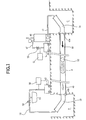
- Fig. 1 is an explanatory view illustrating a method of lining the internal surface of an existing underground pipe, according to the first aspect of the present invention.
- Fig. 2 is an explanatory view illustrating a method of lining the internal surface of an existing underground main pipe involving a branch pipe, according to the second aspect of the present invention.
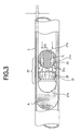
- Fig. 3 is a cross sectional and partially elevational view illustrating a pig apparatus in operation in a branch pipe, according to the second aspect of the present invention.
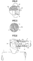
- Fig.4 is an elevational and partially sectional view illustrating a front pig member of the pig apparatus shown in Fig. 3
- Fig. 5 is a cross sectional view illustrating a rear pig member of the pig apparatus shown in Fig. 3.
- Fig. 6 is an elevational and partially sectional view illustrating the operation of the pig apparatus, according to the second aspect of the present invention.
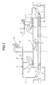
- Fig. 7 is an explanatory view illustrating an airtight test performed on the branch pipe after it has been lined with a resin and isolated from the main pipe, according to the second aspect of the present invention.
- Fig. 8 is an explanatory view illustrating a method of lining the internal surface of an existing underground pipe involving a larger diameter portion, according to the third aspect of the present invention.
- Fig. 9 is an elevational and partially sectional view illustrating a front pig member and a rear pig member used in the method according to the third aspect of the present invention.
- Fig. 10 is an explanatory view illustrating a conventional method of lining the internal surface of an existing underground pipe.
- Fig. 11 is an explanatory view illustrating a conventional method of lining the internal surface of an existing underground pipe involving a branch pipe.
- Fig. 12 is an explanatory view illustrating a conventional method of lining the internal surface of an existing underground pipe involving a branch pipe.
- reference numeral 40 is an existing underground pipe, the internal surface of which is to be coated with a resin for purposes of interior surface repair or rehabilitation.
- a pit B and a pit C are respectively dug to have both ends of the pipe 40 exposed.
- various equipments for the resin lining treatment are arranged and connected in a manner as shown in Fig. 1.
- a pressurized air is supplied through a hose 57 into a resin tank 46, so that a necessary amount of resin received beforehand in the resin tank 46 is introduced into the underground pipe 40 through a hose 41 and an inlet pipe section 54.
- a lining pig 52 is introduced behind the resin A into the pipe 40 through the inlet pipe section 54.
- the resin A and the lining pig 52 begin to move forwardly from one end 40a toward other end 40b of the existing pipe 40.
- a valve 58 is opened and a suction pump 42 is operated, so that a negative pressure ( a suction force ) is applied in front of the resin A in the pipe 40 , by way of a hose 56 and an outlet pipe section 53.
- the resin A and lining pig 52 are forced to move through the pipe 40 by a pressure differential caused by the positive pressure and the negative pressure, the positive pressure being applied behind the resin A and the lining pig 52 is allowed to be greatly lowered, as compared with a conventional method where merely a positive pressure ( a pushing force ) is employed.
- the air blower 48 is provided with a pressure detecting/controlling means 51 to detect the positive pressure within the pipe 40 and control the air blower 48 so that the positive pressure in the pipe 40 may be constantly maintained within a predetermined range.
- the suction pump 42 is also provided with a pressure detecting/controlling means 50 to detect the negative pressure in the pipe 40 and control the suction pump 42 so that the negative pressure in the pipe 40 may be constantly maintained within a predetermined range. Therefore, a pressure differential across the resin A and the lining pig 52 can be constantly maintained within a desired predetermined range, irrespective of various pressure changes possibly occurred within the pipe 40.
- the resin A and the lining pig 52 With the use of thus stabilized pressure differential, the resin A and the lining pig 52 will move in a stabilized speed so as to obtain a stabilized resin lining speed. In this way, it is allowed to form an even resin lining layer having a uniform thickness on the internal surface of the pipe 40. Also, since the positive pressure being applied behind the resin A and the lining pig 52 is greatly lowered as compared with a conventional method which employs a positive pressure only, it becomes possible to prevent a problem of resin blow-off which otherwise will occur on the resin lining layer M which has just been formed on the internal surface of the pipe 40. Besides, with the use of this method, since a negative pressure is also greatly lowered as compared with a conventional method which use a negative pressure ( suction force ) only, it becomes possible for the resin to fill the corrosion pits or pin holes on the pipe interior surface.
- Fig. 2 is an explanatory view illustrating a method of lining the internal surface of an existing underground pipe involving a branch pipe, according to the second aspect of the present invention.
- reference numeral 1 is an existing underground pipe ( hereinafter referred to as main pipe )
- reference numeral 2 is a branch pipe branching from the main pipe I through a service tee 2b.
- the internal surfaces of of both the main pipe 1 and the branch pipe 2 are to be coated with a resin for purposes of interior surface repair and rehabilitation.
- a pit B and a pit C are respectively dug to have both ends of the pipe 1 exposed.
- various equipments for the resin lining treatment are arranged and connected in a manner as shown in Fig. 2.
- a resin tank 4 is connected with an open end la of the pipe I through a hose 3 and an inlet pipe section 9a.
- An air blower 5 is connected with the resin tank 4 through a hose 5a and a valve 7.
- the air blower 5 is provided with a pressure detecting/controlling means 8 for detecting a positive pressure in the pipe 1 and for controlling the operation of the air blower 5 to have the positive pressure in the pipe 1 maintained within a predetermined range.
- a suction pump 11 is connected with the other open end 1b of the pipe 1 through a hose 10, a valve 13 and an outlet pipe section 9b. Also, the suction pump 11 is preferably provided with a pressure detecting/controlling means 14 for detecting a negative pressure in the pipe 1 and for controlling the operation of the suction pump 11 to have the negative pressure in the pipe 1 maintained within a predetermined range.
- a resin receiver 12 is connected with the hose 10 to recover extra resin from the resin lining operation.
- a resin cassette 21 which is filled with a necessary amount of resin for coating the internal surface of the branch pipe 2.
- the other end of the resin cassette 21 is connected through a change-over means 22, to the air blower 5 via a hose 23 ( involving a valve 25 ) and the hose 5a, and to the suction pump 11 via a hose 24 ( involving a valve 26 ) and the hose lla. Therefore, by properly operating the change-over means 22, it is possible to apply either a positive pressure or a negative pressure into the branch pipe 2 through the resin cassette 21.
- a pig apparatus 27 is provided to perform a resin lining treatment in the branch pipe 2.
- the pig apparatus 27 comprises a front ball-like pig member 27a and a rear ball-like pig member 27b, both of which are connected with each other by elongate flexible means 28 such as a rope.
- Each of the pig members 27a and 27b has an appropriate outer diameter such that a resin lining layer having a thickness j may be formed on the internal surface of the branch pipe 2.
- the front ball-like pig member 27a has, around its rear portion at a position offset from the center point of the ball, an reversible skirt-like diaphragm 29 which is made of a cloth, a leather, a synthetic leather or other materials. Further, the reversible skirt-like diaphragm 29 is constructed such that the diaphragm 29 will be reversed at the moment the front ball-like pig member 27a is changed in its moving direction.
- the rear ball-like pig member 27b has a plurality of through holes 31 which are horizontally formed through the pig member 27b.
- each of the through holes 31 includes a large diameter portion 31a and a small diameter portion 31b, as shown in Fig. 3.
- Each of the large diameter portions 31a contains a ball member 30 having a diameter larger than that of the small diameter portion 31b, and has an annular opening 31c on the ball surface which allows air passing but stops the ball member 30.
- each of the through holes 31 including the large diameter portion 31a and a small diameter portion 31b, together with the ball member 30 and the annular opening 31c, constitute a kind of valve means, such that when the rear ball-like pig member 27b is moving forwardly the valve means are opened, whereas when the rear pig member 27b is moving backwardly the valve means are closed.
- a positive pressure is applied behind the pig apparatus 27, the valve means are opened so that the pig apparatus 27 as a whole will move forwardly.
- a negative pressure a suction force
- the resin cassette 21 loaded with a necessary amount of resin A' for lining the internal surface of the branch pipe 2 and loaded with the pig apparatus 27 for such lining treatment is connected with the open end 2a of the branch pipe 2.
- the change-over means 22 is operated and the valve 25 is opened such that the resin cassette 21 becomes communicated with the air blower 5.
- the resin A' together with the pig apparatus 27 are introduced into the branch pipe 2 and moved forward therethrough, so that a resin lining layer having a thickness j is formed on the internal surface of the branch pipe 2, as shown in Fig. 3.
- the pig apparatus 27 will stop automatically because the resin A is used up and an air way is formed therethrough so that the positive pressure from behind is no longer effective on the pig apparatus 27.
- the change-over means 22 is operated again and the valve 26 is opened such that the resin cassette 21 becomes communicated with the suction pump 11,
- a negative pressure (a suction force ) is applied on the pig apparatus 27 through the hose 24 and the resin cassette 21, in such an appropriate extent that the pig apparatus 27 is slightly drawn back and stopped in a position shown by the solid line in Fig.
- the resin A and the lining pig 6 will move in a stabilized speed so as to obtain a stabilized resin lining speed. In this way, it is allowed to form an even resin lining layer having a uniform thickness on the internal surface of the pipe 1.
- the change-over means 22 is operated once more and valve 25 is opened again to have the branch pipe 2 communicated with the air blower 5.
- the air blower 5 By operating the air blower 5, a positive pressure is applied behind the pig apparatus 27 in the branch pipe 2, so that the pig apparatus 27 drops into the main pipe 1 and is removed therefrom through the outlet pipe section 9b.
- Fig. 7 is an explanatory view illustrating an airtight test on the branch pipe 2 which has already been lined with the resin. In practice, such airtight test may be performed at the same time while the main pipe I is being treated in the lining process. As shown in Fig. 7, an airtight test unit including a pressure gauge 32 ( automatically recording type ) and a connecting section 33, is connected with the open end 2a of the branch pipe 2.
- a pressure gauge 32 automatically recording type
- connecting section 33 is connected with the open end 2a of the branch pipe 2.
- a pressure condition ( negative pressure ) within the branch pipe 2 can be correctly read on the pressure gauge 32 and be recorded thereon. In this way, it is possible to know whether there is a leakage in the branch pipe 2 or not, so as to determined whether the lining treatment on the branch pipe 2 is completed.
- Fig. 8 is an explanatory view illustrating a method of lining the internal surface of an existing underground pipe 60 involving a larger diameter portion 62.
- a first or front pig 63 is introduced into the pipe 60 from an open end thereof, then a necessary amount of resin A for lining the internal surface of the pipe 60 is injected behind the first pig 63 into the pipe 60.
- a second or rear pig 64 is inserted behind the resin A into the pipe 60.
- a positive pressure is provided and applied behind the second pig 64 in the pipe 60, so that the first pig 63, the resin A and the second pig 64 are forced to move through the pipe 60 along the entire length thereof.
- a resin lining layer 60a is formed on the internal surface of the pipe 60, by means of the second pig 64.
- the first pig 63 is a spherical body made of a resilient material having a diameter i larger than the pipe inner diameter h and having a number of grooves 65 formed on the spherical surface thereof in a predetermined arrangement.
- the second pig 64 has a diameter g smaller than the pipe inner diameter h , such that a resin lining layer having a desired thickness f may be formed on the internal surface of the pipe 60.
- the first pig 63 when the first pig 63, the resin A and the second pig 64 are moving through the pipe 60 ( have not yet arrived at a larger diameter portion 62 such as a expansion joint ), the first pig 63 is moving with itself under a compressed condition.
- the pig 63 and the resin A arrive at the larger diameter portion 62, although the first pig 63 will still get into a tight contact with the interior surface of the larger diameter portion 62, some residual air remaining in the inner corners of the larger diameter portion 62 is allowed to smoothly escape forwardly, by way of the many grooves 65 formed on the surface of the first pig 63. In this way, the larger diameter portion 62 is completely filled with the resin A, thus its interior surface may be properly coated with the resin.
Landscapes
- Engineering & Computer Science (AREA)
- General Engineering & Computer Science (AREA)
- Mechanical Engineering (AREA)
- Chemical & Material Sciences (AREA)
- Combustion & Propulsion (AREA)
- Physics & Mathematics (AREA)
- Fluid Mechanics (AREA)
- Application Of Or Painting With Fluid Materials (AREA)
- Protection Of Pipes Against Damage, Friction, And Corrosion (AREA)
- Pipe Accessories (AREA)
- Coating Apparatus (AREA)
- Rigid Pipes And Flexible Pipes (AREA)
Priority Applications (1)
| Application Number | Priority Date | Filing Date | Title |
|---|---|---|---|
| EP97200935A EP0789180B1 (fr) | 1994-11-14 | 1995-11-02 | Méthode de revêtement de la surface intérieure d'un tuyau |
Applications Claiming Priority (6)
| Application Number | Priority Date | Filing Date | Title |
|---|---|---|---|
| JP6279253A JP2807754B2 (ja) | 1994-11-14 | 1994-11-14 | 既設管の内面ライニング装置 |
| JP279253/94 | 1994-11-14 | ||
| JP7194695A JPH08267005A (ja) | 1995-03-29 | 1995-03-29 | 既設配管の修理工法 |
| JP71946/95 | 1995-03-29 | ||
| JP26749195A JP3705551B2 (ja) | 1995-10-16 | 1995-10-16 | 既設配管系の更生修理工法 |
| JP267491/95 | 1995-10-16 |
Related Child Applications (1)
| Application Number | Title | Priority Date | Filing Date |
|---|---|---|---|
| EP97200935A Division EP0789180B1 (fr) | 1994-11-14 | 1995-11-02 | Méthode de revêtement de la surface intérieure d'un tuyau |
Publications (2)
| Publication Number | Publication Date |
|---|---|
| EP0713048A1 true EP0713048A1 (fr) | 1996-05-22 |
| EP0713048B1 EP0713048B1 (fr) | 1999-03-24 |
Family
ID=27300818
Family Applications (2)
| Application Number | Title | Priority Date | Filing Date |
|---|---|---|---|
| EP97200935A Expired - Lifetime EP0789180B1 (fr) | 1994-11-14 | 1995-11-02 | Méthode de revêtement de la surface intérieure d'un tuyau |
| EP95307817A Expired - Lifetime EP0713048B1 (fr) | 1994-11-14 | 1995-11-02 | Procédé de recouvrement de la surface intérieure d'un tuyau |
Family Applications Before (1)
| Application Number | Title | Priority Date | Filing Date |
|---|---|---|---|
| EP97200935A Expired - Lifetime EP0789180B1 (fr) | 1994-11-14 | 1995-11-02 | Méthode de revêtement de la surface intérieure d'un tuyau |
Country Status (5)
| Country | Link |
|---|---|
| US (3) | US5609186A (fr) |
| EP (2) | EP0789180B1 (fr) |
| CA (1) | CA2162436C (fr) |
| DE (2) | DE69508526T2 (fr) |
| ES (2) | ES2131774T3 (fr) |
Cited By (6)
| Publication number | Priority date | Publication date | Assignee | Title |
|---|---|---|---|---|
| US6880195B1 (en) | 1999-04-17 | 2005-04-19 | P.A.C.T. Engineering (Scotland) Limited | Pipe cleaning device |
| EP1773510A2 (fr) * | 2004-06-18 | 2007-04-18 | Plastocor, Inc. | Systeme et procede de chemisage de tubes |
| WO2008081441A1 (fr) * | 2007-01-01 | 2008-07-10 | Curapipe System Ltd. | Procédé de réparation de fuite dans des canalisations |
| CN102494221A (zh) * | 2011-12-07 | 2012-06-13 | 中联重科股份有限公司 | 弹性阻尼器、布料臂架及混凝土布料设备 |
| GB2529723A (en) * | 2014-09-01 | 2016-03-02 | Schlumberger Holdings | Corrosion inhibition |
| US11235347B2 (en) | 2015-07-10 | 2022-02-01 | Plastocor, Inc. | System and method for coating tubes |
Families Citing this family (19)
| Publication number | Priority date | Publication date | Assignee | Title |
|---|---|---|---|---|
| CA2184338C (fr) * | 1995-09-06 | 2000-11-14 | Shigeru Toyoda | Procede de reparation in situ de canalisations |
| US5779948A (en) * | 1996-03-11 | 1998-07-14 | Perkins, Deceased; Alfred G. | Method of lining a pipeline using a constant extrusion pressure |
| JP3300268B2 (ja) * | 1997-12-10 | 2002-07-08 | 東京瓦斯株式会社 | 既設管路の更生修理工法 |
| NL1010201C2 (nl) * | 1998-09-28 | 2000-03-30 | Brubek B V | Werkwijze en inrichting voor het aanbrengen van een beschermende film van bijvoorbeeld olie aan de binnenzijde van een metalen pijp. |
| US6746000B2 (en) | 1999-01-29 | 2004-06-08 | Ichimatsu Denki Koji Co., Ltd. | Line-inserting method, line for inserting and optical transmission line for inserting |
| GB0100876D0 (en) * | 2001-01-12 | 2001-02-21 | Lattice Intellectual Property | Lining Pipes |
| GB2372055B (en) * | 2001-02-07 | 2004-09-22 | Petroleo Brasileiro Sa | Method of diminishing the cross section of an opening of a hollow device located in a flow pipe |
| US20060257559A1 (en) * | 2005-05-11 | 2006-11-16 | Warren Danny R | Method and system for insitu repair of interior water pipes |
| JP4842869B2 (ja) * | 2007-03-28 | 2011-12-21 | 株式会社湘南合成樹脂製作所 | 管路を流体で満たすための補助具および管路に流体を注入するための流体注入方法 |
| US20100205757A1 (en) * | 2009-02-18 | 2010-08-19 | Munden Bruce A | Bypass pig |
| US8025738B2 (en) * | 2009-02-18 | 2011-09-27 | Misc B.V. | Method of treating a tubular string using a pigtrain |
| US20100205822A1 (en) * | 2009-02-18 | 2010-08-19 | Munden Bruce A | Method of drying a tubular string to prevent bedwrap corrosion |
| US8328969B2 (en) | 2011-01-04 | 2012-12-11 | Gearhart Stephen V | Method and system for curing pipe liners using microwave energy |
| WO2016019451A1 (fr) | 2014-08-08 | 2016-02-11 | Envirologics Engineering Inc. | Procédé et appareil pour revêtir l'intérieur d'une canalisation de manière homogène |
| US11009171B2 (en) | 2014-12-18 | 2021-05-18 | Curapipe System Ltd. | Systems, compositions and methods for curing leakages in pipes |
| EP3640517B1 (fr) * | 2014-12-18 | 2021-09-22 | Curapipe System Ltd. | Procédé de durcissement de fuites dans des tuyaux |
| CN104879599B (zh) * | 2015-04-29 | 2016-11-30 | 中国建筑第二工程局有限公司 | 一种管道气动通球装置及通球试验方法 |
| CN106764247B (zh) * | 2016-11-23 | 2018-10-12 | 中国计量大学 | 压力管道内球形检测器运动控制方法 |
| US20230102801A1 (en) * | 2021-09-29 | 2023-03-30 | Exotex, Inc. | Pipe reconditioning system |
Citations (5)
| Publication number | Priority date | Publication date | Assignee | Title |
|---|---|---|---|---|
| US4397890A (en) * | 1982-01-29 | 1983-08-09 | Osaka Gas Company, Limited | Method of lining pipes |
| FR2536498A1 (fr) * | 1982-11-19 | 1984-05-25 | Hakko Co | Piston racleur pour la reparation de parties interieures d'un pipe-line |
| US5230842A (en) * | 1989-02-21 | 1993-07-27 | Munde Bruce A | Interior pipeline coating process |
| JPH05228437A (ja) * | 1992-02-19 | 1993-09-07 | Tokyo Gas Co Ltd | 吸引ライニングによる管路の補修工法 |
| EP0593264A1 (fr) * | 1992-10-14 | 1994-04-20 | Tokyo Gas Co., Ltd. | Procédé de revêtement de la surface intérieure d'un tuyau |
Family Cites Families (14)
| Publication number | Priority date | Publication date | Assignee | Title |
|---|---|---|---|---|
| US3041204A (en) * | 1959-03-24 | 1962-06-26 | Leland W Green | Internal conduit coating method and apparatus |
| US3640299A (en) * | 1969-10-06 | 1972-02-08 | Acf Ind Inc | Subsea wellhead control system |
| US3662045A (en) * | 1970-04-24 | 1972-05-09 | Kenneth Tierling | Method for providing a cement sheathed plastic liner within a flowline |
| US4440194A (en) * | 1980-02-29 | 1984-04-03 | Osaka Gas Company, Limited | Moving body and method of performing work within pipes with use of same |
| DE3046608C2 (de) * | 1980-12-11 | 1983-11-17 | diga - die gasheizung GmbH, 4300 Essen | Molch zum Auskleiden von Rohrleitungen |
| US4456401A (en) * | 1981-11-09 | 1984-06-26 | Finic, B.V. | Method and apparatus for relining underground passageway |
| US4602974A (en) * | 1981-12-31 | 1986-07-29 | Eric Wood | Method of sealing pipe |
| JPS5949870A (ja) * | 1982-09-11 | 1984-03-22 | Kankyo Kaihatsu:Kk | 既設埋設管補強、補修装置のパツカ− |
| JPS5962375A (ja) * | 1982-09-30 | 1984-04-09 | Suriibondo:Kk | 覆土導管の漏洩孔シール方法 |
| JPS60253626A (ja) * | 1984-05-30 | 1985-12-14 | Nippon Telegr & Teleph Corp <Ntt> | 地下管路の補修用ピグ装置 |
| JPS62186968A (ja) * | 1986-02-13 | 1987-08-15 | Osaka Bosui Kensetsushiya:Kk | 異径管路内面のライニング装置 |
| JPH0729078B2 (ja) * | 1986-12-05 | 1995-04-05 | 大阪瓦斯株式会社 | 管内面ライニング用物体 |
| US4985196B1 (en) * | 1987-10-30 | 1997-11-18 | Pipe Liners Inc | Pipe liner process |
| US5202157A (en) * | 1990-08-28 | 1993-04-13 | Mitsui Petrochemical Industries, Ltd. | Method for lining internal surfaces of pipelines |
-
1995
- 1995-11-01 US US08/548,300 patent/US5609186A/en not_active Expired - Fee Related
- 1995-11-02 EP EP97200935A patent/EP0789180B1/fr not_active Expired - Lifetime
- 1995-11-02 DE DE69508526T patent/DE69508526T2/de not_active Expired - Fee Related
- 1995-11-02 EP EP95307817A patent/EP0713048B1/fr not_active Expired - Lifetime
- 1995-11-02 ES ES95307817T patent/ES2131774T3/es not_active Expired - Lifetime
- 1995-11-02 DE DE69522464T patent/DE69522464T2/de not_active Expired - Fee Related
- 1995-11-02 ES ES97200935T patent/ES2160886T3/es not_active Expired - Lifetime
- 1995-11-08 CA CA002162436A patent/CA2162436C/fr not_active Expired - Fee Related
-
1996
- 1996-07-19 US US08/685,026 patent/US5740838A/en not_active Expired - Fee Related
- 1996-07-19 US US08/685,028 patent/US5873390A/en not_active Expired - Fee Related
Patent Citations (5)
| Publication number | Priority date | Publication date | Assignee | Title |
|---|---|---|---|---|
| US4397890A (en) * | 1982-01-29 | 1983-08-09 | Osaka Gas Company, Limited | Method of lining pipes |
| FR2536498A1 (fr) * | 1982-11-19 | 1984-05-25 | Hakko Co | Piston racleur pour la reparation de parties interieures d'un pipe-line |
| US5230842A (en) * | 1989-02-21 | 1993-07-27 | Munde Bruce A | Interior pipeline coating process |
| JPH05228437A (ja) * | 1992-02-19 | 1993-09-07 | Tokyo Gas Co Ltd | 吸引ライニングによる管路の補修工法 |
| EP0593264A1 (fr) * | 1992-10-14 | 1994-04-20 | Tokyo Gas Co., Ltd. | Procédé de revêtement de la surface intérieure d'un tuyau |
Non-Patent Citations (1)
| Title |
|---|
| PATENT ABSTRACTS OF JAPAN vol. 017, no. 685 (C - 1142) 15 December 1993 (1993-12-15) * |
Cited By (14)
| Publication number | Priority date | Publication date | Assignee | Title |
|---|---|---|---|---|
| US6880195B1 (en) | 1999-04-17 | 2005-04-19 | P.A.C.T. Engineering (Scotland) Limited | Pipe cleaning device |
| US8359996B2 (en) | 2004-06-18 | 2013-01-29 | Plastocor, Inc. | System and method for coating tubes |
| EP1773510A2 (fr) * | 2004-06-18 | 2007-04-18 | Plastocor, Inc. | Systeme et procede de chemisage de tubes |
| EP1773510A4 (fr) * | 2004-06-18 | 2007-10-24 | Plastocor Inc | Systeme et procede de chemisage de tubes |
| US7717056B2 (en) | 2004-06-18 | 2010-05-18 | Plastocor, Inc. | System and method for coating tubes |
| WO2008081441A1 (fr) * | 2007-01-01 | 2008-07-10 | Curapipe System Ltd. | Procédé de réparation de fuite dans des canalisations |
| US9045648B2 (en) | 2007-01-01 | 2015-06-02 | Curapipe System Ltd. | Method of repairing leakage in pipelines |
| US9738798B2 (en) | 2007-01-01 | 2017-08-22 | Curapipe System Ltd. | Method of repairing leakage in pipelines |
| CN102494221A (zh) * | 2011-12-07 | 2012-06-13 | 中联重科股份有限公司 | 弹性阻尼器、布料臂架及混凝土布料设备 |
| CN102494221B (zh) * | 2011-12-07 | 2014-04-16 | 中联重科股份有限公司 | 弹性阻尼器、布料臂架及混凝土布料设备 |
| GB2529723A (en) * | 2014-09-01 | 2016-03-02 | Schlumberger Holdings | Corrosion inhibition |
| GB2529723B (en) * | 2014-09-01 | 2017-04-05 | Schlumberger Holdings | A method of corrosion inhibition of metal |
| US10794527B2 (en) | 2014-09-01 | 2020-10-06 | Schlumberger Technology Corporation | Corrosion inhibition |
| US11235347B2 (en) | 2015-07-10 | 2022-02-01 | Plastocor, Inc. | System and method for coating tubes |
Also Published As
| Publication number | Publication date |
|---|---|
| DE69522464D1 (de) | 2001-10-04 |
| DE69522464T2 (de) | 2001-12-13 |
| CA2162436C (fr) | 2000-01-25 |
| US5609186A (en) | 1997-03-11 |
| DE69508526D1 (de) | 1999-04-29 |
| US5740838A (en) | 1998-04-21 |
| CA2162436A1 (fr) | 1996-05-15 |
| US5873390A (en) | 1999-02-23 |
| EP0789180A2 (fr) | 1997-08-13 |
| EP0713048B1 (fr) | 1999-03-24 |
| EP0789180A3 (fr) | 1997-09-24 |
| EP0789180B1 (fr) | 2001-08-29 |
| ES2131774T3 (es) | 1999-08-01 |
| DE69508526T2 (de) | 1999-07-08 |
| ES2160886T3 (es) | 2001-11-16 |
Similar Documents
| Publication | Publication Date | Title |
|---|---|---|
| US5609186A (en) | Methods of lining the internal surface of a pipe | |
| US5439033A (en) | Method of lining a branch pipe | |
| EP0624749B1 (fr) | Procédé de réparation de conduites | |
| US4556580A (en) | Method of repairing pipes laid underground | |
| WO1991010555A1 (fr) | Ameliorations relatives a la doublure de conduites et canalisations | |
| US5983948A (en) | Method of repairing an existing pipeline including a main pipe and a branch pipe | |
| GB2215806A (en) | Lining pipes | |
| JP3231472B2 (ja) | 配管の更生方法 | |
| CA2184338C (fr) | Procede de reparation in situ de canalisations | |
| JP2977602B2 (ja) | 管路内面のライニング方法 | |
| JP3352816B2 (ja) | 厚膜ライニング工法 | |
| JPH0663504A (ja) | 多岐配管の管路内面のライニング方法 | |
| JP3117895B2 (ja) | 既設配管の修理工法 | |
| JPS6110632A (ja) | 既設配管の補修施工法 | |
| JP3608718B2 (ja) | 分岐管路の内壁面更生方法及びその装置 | |
| JP3167253B2 (ja) | 既設配管の更生修理工法 | |
| JPH08267005A (ja) | 既設配管の修理工法 | |
| JPS61103568A (ja) | 既設配管の管内面補修工法 | |
| JPH0346192B2 (fr) | ||
| JPH0649182B2 (ja) | 管内面のライニング補修工法 | |
| JPS5938028B2 (ja) | 既設埋設管等の漏洩防止工法 | |
| JPH0260395B2 (fr) | ||
| JPH09225398A (ja) | 既設管路のライニング工法 | |
| JPH0321225B2 (fr) | ||
| JPS6226834B2 (fr) |
Legal Events
| Date | Code | Title | Description |
|---|---|---|---|
| PUAI | Public reference made under article 153(3) epc to a published international application that has entered the european phase |
Free format text: ORIGINAL CODE: 0009012 |
|
| 17P | Request for examination filed |
Effective date: 19951128 |
|
| AK | Designated contracting states |
Kind code of ref document: A1 Designated state(s): DE ES FR GB IT |
|
| 17Q | First examination report despatched |
Effective date: 19961030 |
|
| GRAG | Despatch of communication of intention to grant |
Free format text: ORIGINAL CODE: EPIDOS AGRA |
|
| GRAG | Despatch of communication of intention to grant |
Free format text: ORIGINAL CODE: EPIDOS AGRA |
|
| GRAH | Despatch of communication of intention to grant a patent |
Free format text: ORIGINAL CODE: EPIDOS IGRA |
|
| GRAH | Despatch of communication of intention to grant a patent |
Free format text: ORIGINAL CODE: EPIDOS IGRA |
|
| GRAA | (expected) grant |
Free format text: ORIGINAL CODE: 0009210 |
|
| AK | Designated contracting states |
Kind code of ref document: B1 Designated state(s): DE ES FR GB IT |
|
| XX | Miscellaneous (additional remarks) |
Free format text: TEILANMELDUNG 97200935.1 EINGEREICHT AM 01/04/97. |
|
| ET | Fr: translation filed | ||
| REF | Corresponds to: |
Ref document number: 69508526 Country of ref document: DE Date of ref document: 19990429 |
|
| REG | Reference to a national code |
Ref country code: ES Ref legal event code: FG2A Ref document number: 2131774 Country of ref document: ES Kind code of ref document: T3 |
|
| PLBE | No opposition filed within time limit |
Free format text: ORIGINAL CODE: 0009261 |
|
| STAA | Information on the status of an ep patent application or granted ep patent |
Free format text: STATUS: NO OPPOSITION FILED WITHIN TIME LIMIT |
|
| 26N | No opposition filed | ||
| REG | Reference to a national code |
Ref country code: GB Ref legal event code: IF02 |
|
| PGFP | Annual fee paid to national office [announced via postgrant information from national office to epo] |
Ref country code: GB Payment date: 20041027 Year of fee payment: 10 |
|
| PGFP | Annual fee paid to national office [announced via postgrant information from national office to epo] |
Ref country code: DE Payment date: 20041028 Year of fee payment: 10 |
|
| PGFP | Annual fee paid to national office [announced via postgrant information from national office to epo] |
Ref country code: FR Payment date: 20041109 Year of fee payment: 10 |
|
| PGFP | Annual fee paid to national office [announced via postgrant information from national office to epo] |
Ref country code: ES Payment date: 20041214 Year of fee payment: 10 |
|
| PG25 | Lapsed in a contracting state [announced via postgrant information from national office to epo] |
Ref country code: IT Free format text: LAPSE BECAUSE OF NON-PAYMENT OF DUE FEES;WARNING: LAPSES OF ITALIAN PATENTS WITH EFFECTIVE DATE BEFORE 2007 MAY HAVE OCCURRED AT ANY TIME BEFORE 2007. THE CORRECT EFFECTIVE DATE MAY BE DIFFERENT FROM THE ONE RECORDED. Effective date: 20051102 Ref country code: GB Free format text: LAPSE BECAUSE OF NON-PAYMENT OF DUE FEES Effective date: 20051102 |
|
| PG25 | Lapsed in a contracting state [announced via postgrant information from national office to epo] |
Ref country code: ES Free format text: LAPSE BECAUSE OF NON-PAYMENT OF DUE FEES Effective date: 20051103 |
|
| PG25 | Lapsed in a contracting state [announced via postgrant information from national office to epo] |
Ref country code: DE Free format text: LAPSE BECAUSE OF NON-PAYMENT OF DUE FEES Effective date: 20060601 |
|
| GBPC | Gb: european patent ceased through non-payment of renewal fee |
Effective date: 20051102 |
|
| PG25 | Lapsed in a contracting state [announced via postgrant information from national office to epo] |
Ref country code: FR Free format text: LAPSE BECAUSE OF NON-PAYMENT OF DUE FEES Effective date: 20060731 |
|
| REG | Reference to a national code |
Ref country code: FR Ref legal event code: ST Effective date: 20060731 |
|
| REG | Reference to a national code |
Ref country code: ES Ref legal event code: FD2A Effective date: 20051103 |