EP0706906A2 - Verfahren und Vorrichtung zum Steuern der Dämpfungskraft der Radaufhängung eines Fahrzeugs - Google Patents
Verfahren und Vorrichtung zum Steuern der Dämpfungskraft der Radaufhängung eines Fahrzeugs Download PDFInfo
- Publication number
- EP0706906A2 EP0706906A2 EP95115893A EP95115893A EP0706906A2 EP 0706906 A2 EP0706906 A2 EP 0706906A2 EP 95115893 A EP95115893 A EP 95115893A EP 95115893 A EP95115893 A EP 95115893A EP 0706906 A2 EP0706906 A2 EP 0706906A2
- Authority
- EP
- European Patent Office
- Prior art keywords
- road wheel
- sprung mass
- wheel position
- right road
- denotes
- Prior art date
- Legal status (The legal status is an assumption and is not a legal conclusion. Google has not performed a legal analysis and makes no representation as to the accuracy of the status listed.)
- Withdrawn
Links
- 238000013016 damping Methods 0.000 title claims abstract description 155
- 238000000034 method Methods 0.000 title claims abstract description 9
- 239000000725 suspension Substances 0.000 title claims description 62
- 239000006096 absorbing agent Substances 0.000 claims abstract description 130
- 230000035939 shock Effects 0.000 claims abstract description 130
- 238000012546 transfer Methods 0.000 claims abstract description 129
- 230000006870 function Effects 0.000 claims description 106
- 230000001133 acceleration Effects 0.000 claims description 89
- 230000006835 compression Effects 0.000 claims description 44
- 238000007906 compression Methods 0.000 claims description 44
- 238000012937 correction Methods 0.000 claims description 19
- 230000004044 response Effects 0.000 claims description 10
- GNFTZDOKVXKIBK-UHFFFAOYSA-N 3-(2-methoxyethoxy)benzohydrazide Chemical compound COCCOC1=CC=CC(C(=O)NN)=C1 GNFTZDOKVXKIBK-UHFFFAOYSA-N 0.000 claims description 4
- FGUUSXIOTUKUDN-IBGZPJMESA-N C1(=CC=CC=C1)N1C2=C(NC([C@H](C1)NC=1OC(=NN=1)C1=CC=CC=C1)=O)C=CC=C2 Chemical compound C1(=CC=CC=C1)N1C2=C(NC([C@H](C1)NC=1OC(=NN=1)C1=CC=CC=C1)=O)C=CC=C2 FGUUSXIOTUKUDN-IBGZPJMESA-N 0.000 claims description 2
- 230000006399 behavior Effects 0.000 abstract description 17
- 238000012545 processing Methods 0.000 description 18
- 239000012530 fluid Substances 0.000 description 11
- 239000008186 active pharmaceutical agent Substances 0.000 description 8
- 238000004364 calculation method Methods 0.000 description 5
- 238000010586 diagram Methods 0.000 description 5
- 101710179734 6,7-dimethyl-8-ribityllumazine synthase 2 Proteins 0.000 description 4
- 101710178035 Chorismate synthase 2 Proteins 0.000 description 4
- 101710152694 Cysteine synthase 2 Proteins 0.000 description 4
- 101710186609 Lipoyl synthase 2 Proteins 0.000 description 4
- 101710122908 Lipoyl synthase 2, chloroplastic Proteins 0.000 description 4
- 101710101072 Lipoyl synthase 2, mitochondrial Proteins 0.000 description 4
- 238000004891 communication Methods 0.000 description 4
- 230000000149 penetrating effect Effects 0.000 description 4
- 230000002093 peripheral effect Effects 0.000 description 4
- 230000005540 biological transmission Effects 0.000 description 2
- 230000003247 decreasing effect Effects 0.000 description 2
- 238000001914 filtration Methods 0.000 description 2
- 238000004519 manufacturing process Methods 0.000 description 2
- 238000004088 simulation Methods 0.000 description 2
- 238000012360 testing method Methods 0.000 description 2
- 230000009466 transformation Effects 0.000 description 2
- 238000013459 approach Methods 0.000 description 1
- 230000008859 change Effects 0.000 description 1
- 238000010276 construction Methods 0.000 description 1
- 230000008602 contraction Effects 0.000 description 1
- 230000003111 delayed effect Effects 0.000 description 1
- 230000026058 directional locomotion Effects 0.000 description 1
- 230000000694 effects Effects 0.000 description 1
- 238000009313 farming Methods 0.000 description 1
- 230000005484 gravity Effects 0.000 description 1
- 238000009434 installation Methods 0.000 description 1
- 230000033001 locomotion Effects 0.000 description 1
- 230000008569 process Effects 0.000 description 1
Images











Classifications
-
- B—PERFORMING OPERATIONS; TRANSPORTING
- B60—VEHICLES IN GENERAL
- B60G—VEHICLE SUSPENSION ARRANGEMENTS
- B60G17/00—Resilient suspensions having means for adjusting the spring or vibration-damper characteristics, for regulating the distance between a supporting surface and a sprung part of vehicle or for locking suspension during use to meet varying vehicular or surface conditions, e.g. due to speed or load
- B60G17/015—Resilient suspensions having means for adjusting the spring or vibration-damper characteristics, for regulating the distance between a supporting surface and a sprung part of vehicle or for locking suspension during use to meet varying vehicular or surface conditions, e.g. due to speed or load the regulating means comprising electric or electronic elements
- B60G17/018—Resilient suspensions having means for adjusting the spring or vibration-damper characteristics, for regulating the distance between a supporting surface and a sprung part of vehicle or for locking suspension during use to meet varying vehicular or surface conditions, e.g. due to speed or load the regulating means comprising electric or electronic elements characterised by the use of a specific signal treatment or control method
- B60G17/0182—Resilient suspensions having means for adjusting the spring or vibration-damper characteristics, for regulating the distance between a supporting surface and a sprung part of vehicle or for locking suspension during use to meet varying vehicular or surface conditions, e.g. due to speed or load the regulating means comprising electric or electronic elements characterised by the use of a specific signal treatment or control method involving parameter estimation, e.g. observer, Kalman filter
-
- B—PERFORMING OPERATIONS; TRANSPORTING
- B60—VEHICLES IN GENERAL
- B60G—VEHICLE SUSPENSION ARRANGEMENTS
- B60G17/00—Resilient suspensions having means for adjusting the spring or vibration-damper characteristics, for regulating the distance between a supporting surface and a sprung part of vehicle or for locking suspension during use to meet varying vehicular or surface conditions, e.g. due to speed or load
- B60G17/015—Resilient suspensions having means for adjusting the spring or vibration-damper characteristics, for regulating the distance between a supporting surface and a sprung part of vehicle or for locking suspension during use to meet varying vehicular or surface conditions, e.g. due to speed or load the regulating means comprising electric or electronic elements
- B60G17/016—Resilient suspensions having means for adjusting the spring or vibration-damper characteristics, for regulating the distance between a supporting surface and a sprung part of vehicle or for locking suspension during use to meet varying vehicular or surface conditions, e.g. due to speed or load the regulating means comprising electric or electronic elements characterised by their responsiveness, when the vehicle is travelling, to specific motion, a specific condition, or driver input
-
- B—PERFORMING OPERATIONS; TRANSPORTING
- B60—VEHICLES IN GENERAL
- B60G—VEHICLE SUSPENSION ARRANGEMENTS
- B60G17/00—Resilient suspensions having means for adjusting the spring or vibration-damper characteristics, for regulating the distance between a supporting surface and a sprung part of vehicle or for locking suspension during use to meet varying vehicular or surface conditions, e.g. due to speed or load
- B60G17/015—Resilient suspensions having means for adjusting the spring or vibration-damper characteristics, for regulating the distance between a supporting surface and a sprung part of vehicle or for locking suspension during use to meet varying vehicular or surface conditions, e.g. due to speed or load the regulating means comprising electric or electronic elements
- B60G17/0152—Resilient suspensions having means for adjusting the spring or vibration-damper characteristics, for regulating the distance between a supporting surface and a sprung part of vehicle or for locking suspension during use to meet varying vehicular or surface conditions, e.g. due to speed or load the regulating means comprising electric or electronic elements characterised by the action on a particular type of suspension unit
-
- B—PERFORMING OPERATIONS; TRANSPORTING
- B60—VEHICLES IN GENERAL
- B60G—VEHICLE SUSPENSION ARRANGEMENTS
- B60G17/00—Resilient suspensions having means for adjusting the spring or vibration-damper characteristics, for regulating the distance between a supporting surface and a sprung part of vehicle or for locking suspension during use to meet varying vehicular or surface conditions, e.g. due to speed or load
- B60G17/06—Characteristics of dampers, e.g. mechanical dampers
- B60G17/08—Characteristics of fluid dampers
-
- F—MECHANICAL ENGINEERING; LIGHTING; HEATING; WEAPONS; BLASTING
- F16—ENGINEERING ELEMENTS AND UNITS; GENERAL MEASURES FOR PRODUCING AND MAINTAINING EFFECTIVE FUNCTIONING OF MACHINES OR INSTALLATIONS; THERMAL INSULATION IN GENERAL
- F16F—SPRINGS; SHOCK-ABSORBERS; MEANS FOR DAMPING VIBRATION
- F16F9/00—Springs, vibration-dampers, shock-absorbers, or similarly-constructed movement-dampers using a fluid or the equivalent as damping medium
- F16F9/32—Details
- F16F9/44—Means on or in the damper for manual or non-automatic adjustment; such means combined with temperature correction
- F16F9/46—Means on or in the damper for manual or non-automatic adjustment; such means combined with temperature correction allowing control from a distance, i.e. location of means for control input being remote from site of valves, e.g. on damper external wall
- F16F9/466—Throttling control, i.e. regulation of flow passage geometry
- F16F9/467—Throttling control, i.e. regulation of flow passage geometry using rotary valves
- F16F9/468—Throttling control, i.e. regulation of flow passage geometry using rotary valves controlling at least one bypass to main flow path
-
- B—PERFORMING OPERATIONS; TRANSPORTING
- B60—VEHICLES IN GENERAL
- B60G—VEHICLE SUSPENSION ARRANGEMENTS
- B60G2206/00—Indexing codes related to the manufacturing of suspensions: constructional features, the materials used, procedures or tools
- B60G2206/01—Constructional features of suspension elements, e.g. arms, dampers, springs
- B60G2206/40—Constructional features of dampers and/or springs
- B60G2206/41—Dampers
-
- B—PERFORMING OPERATIONS; TRANSPORTING
- B60—VEHICLES IN GENERAL
- B60G—VEHICLE SUSPENSION ARRANGEMENTS
- B60G2400/00—Indexing codes relating to detected, measured or calculated conditions or factors
- B60G2400/10—Acceleration; Deceleration
- B60G2400/102—Acceleration; Deceleration vertical
-
- B—PERFORMING OPERATIONS; TRANSPORTING
- B60—VEHICLES IN GENERAL
- B60G—VEHICLE SUSPENSION ARRANGEMENTS
- B60G2400/00—Indexing codes relating to detected, measured or calculated conditions or factors
- B60G2400/20—Speed
- B60G2400/204—Vehicle speed
-
- B—PERFORMING OPERATIONS; TRANSPORTING
- B60—VEHICLES IN GENERAL
- B60G—VEHICLE SUSPENSION ARRANGEMENTS
- B60G2400/00—Indexing codes relating to detected, measured or calculated conditions or factors
- B60G2400/20—Speed
- B60G2400/206—Body oscillation speed; Body vibration frequency
-
- B—PERFORMING OPERATIONS; TRANSPORTING
- B60—VEHICLES IN GENERAL
- B60G—VEHICLE SUSPENSION ARRANGEMENTS
- B60G2500/00—Indexing codes relating to the regulated action or device
- B60G2500/10—Damping action or damper
-
- B—PERFORMING OPERATIONS; TRANSPORTING
- B60—VEHICLES IN GENERAL
- B60G—VEHICLE SUSPENSION ARRANGEMENTS
- B60G2500/00—Indexing codes relating to the regulated action or device
- B60G2500/10—Damping action or damper
- B60G2500/11—Damping valves
-
- B—PERFORMING OPERATIONS; TRANSPORTING
- B60—VEHICLES IN GENERAL
- B60G—VEHICLE SUSPENSION ARRANGEMENTS
- B60G2600/00—Indexing codes relating to particular elements, systems or processes used on suspension systems or suspension control systems
- B60G2600/18—Automatic control means
- B60G2600/184—Semi-Active control means
-
- B—PERFORMING OPERATIONS; TRANSPORTING
- B60—VEHICLES IN GENERAL
- B60G—VEHICLE SUSPENSION ARRANGEMENTS
- B60G2600/00—Indexing codes relating to particular elements, systems or processes used on suspension systems or suspension control systems
- B60G2600/60—Signal noise suppression; Electronic filtering means
- B60G2600/602—Signal noise suppression; Electronic filtering means high pass
-
- B—PERFORMING OPERATIONS; TRANSPORTING
- B60—VEHICLES IN GENERAL
- B60G—VEHICLE SUSPENSION ARRANGEMENTS
- B60G2600/00—Indexing codes relating to particular elements, systems or processes used on suspension systems or suspension control systems
- B60G2600/60—Signal noise suppression; Electronic filtering means
- B60G2600/604—Signal noise suppression; Electronic filtering means low pass
-
- B—PERFORMING OPERATIONS; TRANSPORTING
- B60—VEHICLES IN GENERAL
- B60G—VEHICLE SUSPENSION ARRANGEMENTS
- B60G2800/00—Indexing codes relating to the type of movement or to the condition of the vehicle and to the end result to be achieved by the control action
- B60G2800/70—Estimating or calculating vehicle parameters or state variables
Definitions
- the present invention relates to apparatus and method for optimally controlling a damping force characteristic of a suspension system of an automotive vehicle, the suspension system having four shock absorbers, each shock absorber being interposed between an sprung mass of the vehicle body and an unsprung mass of a corresponding one of front left and right and rear left and right road wheels.
- a Japanese Patent Application First Publication No. Hesei 4-191109 exemplifies a previously proposed suspension system for controlling a damping force of each shock absorber interposed between a sprung mass of a vehicle body and an unsprung mass of a corresponding one of front left and right road wheels and rear left and right road wheels.
- the previously proposed suspension system includes: an actuator which is so arranged and constructed between the vehicle body and rear road wheels as to enable to increase and decrease a supporting force of a vehicle body on the rear road wheel; vibration input detecting means for detecting a vibration input from each of the front road wheels due to a passage of the vehicle on a road surface convex and recess; vehicle speed detecting means for detecting a vehicle speed; and controlling means for controlling an operation of the actuator on the basis of the inputs from the respective detecting means.
- the controlling means calculates a time point at which the rear road wheels will pass on the same road surface convex and recess which has given the vibration inputs exceeding a predetermined value on the basis of the output vehicle speed of the vehicle speed detecting means when determining that the vibration inputs from the front road wheels have exceeded the predetermined value and is so arranged and constructed as to operate the actuator so that, at that time point, the vibration inputs from the rear road wheels are relieved. That is to say, the previously proposed suspension system carries out a, so-called, preview control such that a timing at which the vibration inputs from the front road wheels are used as correction signals on the respective rear road wheel positioned shock absorbers is delayed (retarded) according to the vehicle speed.
- the preview control such as to refer to the vibration input on the vehicle body at the time of the passages of the front road wheels on the road surface convex and recess is carried out when the rear road wheels pass on the same road surface convex and recess. Consequently, when the rear road wheel passes on the same road surface convex and recess, the vibration input on the vehicle body can be reduced as compared with the vibration input on the vehicle body during the passage of the front road wheels on the road surface convex and recess.
- sensors used to detect the vibration input are individually and independently installed at the respective road wheel attached positions of the front and rear road wheels.
- sensors used to determine sprung mass vertical velocities and relative velocities between the sprung mass and unsprung mass are required to be individually and independently installed at the respective road wheel positions of the front and rear road wheels, its system configuration becomes complex, it is difficult for such sensors as described above to be mounted in the vehicle, and its system structure manufacturing cost becomes accordingly high.
- an apparatus for a vehicular suspension system said suspension system having a plurality of front and rear left and right road wheel positioned shock absorbers, each shock absorber being interposed between a sprung mass of a vehicle body and an unsprung mass of a corresponding one of front left and right road wheels and rear left and right road wheels, said apparatus comprising: a) damping force characteristic varying means for operatively varying a damping force characteristic of each corresponding one of the respective shock absorbers; b) front road wheel position vehicular behavior determining means for determining a vehicular behavior at a front road wheel position of the vehicle body and outputting a first signal indicative of the vehicular behavior at the front road wheel position; c) rear road wheel position vehicular behavior estimating means for estimating the vehicular behavior at a rear road wheel position of the vehicle body from said first signal using a predetermined transfer function between a front road wheel position and a rear road wheel position and outputting a second signal indicative of the vehicular behavior at the rear road
- a method for controlling a damping force characteristic for each of a plurality of vehicular front and rear left and right road wheel positioned shock absorbers constituting a vehicular suspension system each of said shock absorbers being interposed between a sprung mass of a vehicle body and an unsprung mass of a corresponding one of front left and right road wheels and rear left and right road wheels, said method comprising the steps of: a) detecting sprung mass vertical accelerations at front left and right road wheel positions using front road wheel position sprung mass vertical acceleration detecting means; b) converting the detected front left and right road wheel position sprung mass vertical accelerations into corresponding sprung mass vertical velocities at the front left and right road wheel positions, respectively; c) estimating relative velocities between the sprung mass and the unsprung mass at the front left and right road wheel positions from the detected sprung mass vertical accelerations at the step a) at the front left and right road wheel positions, respectively, using a first predetermined transfer function; d)
- Fig. 1 shows a whole system configuration of a vehicular suspension system damping force characteristic controlling apparatus in a first preferred embodiment according to the present invention.
- shock absorbers SA FL , SA FR , SA RL , and SA RR denoted by SA since all shock absorbers (having the mutually same structures) are interposed between given parts of a vehicular body (sprung mass) and respective road (tire) wheels (unsprung mass).
- the road wheels comprise front left road wheel, front right road wheel, rear left road wheel, and rear right road wheel of the vehicle. It is noted that the above-described given parts of the vehicular body indicate front left and right road wheel positions and rear left and right road wheel positions.
- two vertical (.i.e., upward and downward) sprung mass acceleration (G, G; gravity) sensors 1 FL and 1 FR are attached onto given parts (also called, tower positions) of the vehicular body adjacent to the front left and right road wheel side shock absorbers SA (namely, SA FL and SA FR ), each being provided to detect a vertical sprung mass acceleration acted upon the sprung mass (vehicle body).
- a vehicle speed sensor 2 is provided which detects a vehicle speed of the vehicle.
- a control unit 4 is installed at a given part of the vehicle to receive signals derived from the two acceleration sensors 1 FR and 1 FL and from the vehicle speed sensor 2, processes these signals, and outputs finally drive signals to respective actuators (,i.e., stepping motors 3) for the respective four shock absorbers SA (SA FR , SA FL , SA RL , and SA RR ).
- Fig. 2 shows a circuit block diagram of the vehicular shock absorber damping force controlling apparatus in the first embodiment according to the present invention shown in Fig. 1.
- control unit 4 is installed on a portion of the vehicular body near to a driver's seat.
- the control unit 4 includes: an input interface circuit 4a; a CPU (Central Processing Unit) 4b; a memory 4bb having a ROM (Read Only Memory) and a RAM (Random Access Memory); an output interface 4aa, and actuator driver circuits 4c; and a common bus.
- CPU Central Processing Unit
- memory 4bb having a ROM (Read Only Memory) and a RAM (Random Access Memory)
- output interface 4aa and actuator driver circuits 4c
- a common bus a common bus.
- control unit 4 is provided with the respective drivers 4c connected between the output interface 4aa and the corresponding stepping motors 3.
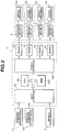
- the control unit 4 shown in Fig. 2 is provided with a signal processing circuit in terms of its hardware structure as shown in Fig. 13.
- the signal processing circuit derives each control signal V (including each target damping force characteristic position P) used to perform a damping force characteristic control for each shock absorber SA.
- the explanation of Fig. 13 will be described later.
- Fig. 3 show a cross sectional view of each shock absorber SA shown in Figs. 1 and 2.
- the shock absorber SA as shown in Fig. 3, includes: a cylinder 30, a (movable) piston 31 defining an upper portion chamber A and a lower portion chamber B; an outer envelope 33 in which a reservoir chamber 32 is formed on an outer peripheral end of the cylinder 30; a base 34 which defines the lower portion chamber B and the reservoir chamber 32; a guide member 35 which guides a sliding motion of a piston rod 7 with the other end of which the movable piston 31 is linked; a suspension spring 36 interposed between the outer envelope 33 and vehicle body; and a bumper rubber 37.
- Each stepping motor 3 shown in Figs. 1 and 2 is installed in an upper position of the corresponding one of the shock absorbers SA, as shown in Fig. 3, so as to operatively rotate an adjuster 40 (refer to Fig. 4) via a control rod 70 in response to a rotation drive signal from the corresponding one of the actuator drivers (circuits) 4c.
- a rotating shaft of the corresponding one of the stepping motors 3 is mechanically connected to the corresponding adjuster 40 within each shock absorbers SA via the control rod 70.
- Fig. 4 shows an enlarged cross sectional view representing a part of the piston assembly 31 and its surrounding part of each of the shock absorbers SA.
- the piston 31 is formed with penetrating holes 31a and 31b therethrough.
- the piston 31 is provided with a compression phase attenuation valve 20 and an extension phase attenuating valve 12, both of the valves 20, 12 respectively opening and closing the respective penetrating holes 31a and 31b.
- a stud 38 is spirally meshed with and fixed to a bound stopper 41 spirally meshed with and fixed to a tip end of the piston rod 7.
- the stud 38 is penetrated through the piston 31.
- the stud 38 is formed with a communication hole 39 so as to communicate the upper portion chamber A and the lower portion chamber B, the communication hole 39 forming flow passages (an extension phase second flow passage E, extension phase third flow passage F, bypass flow passage G, and compression phase second flow passage J as will be described later).
- the adjuster 40 which changes flow passage cross sectional areas of the above-described flow passages is provided within the communication hole 39.
- an extension stroke side (phase) check valve 17 and a compression (or contraction) stroke side (compression phase) check valve 22 are also installed on an outer periphery of the stud 38, which enable and disable the fluid flow through the above-described flow passages formed by the communication hole 39 in accordance with a direction of the flow of the fluid.
- the adjuster 40 is rotatable by means of the corresponding one of the actuators (stepping motors) 3 via the control rod 70.
- the stud 38 is formed with a first port 21, a second port 13, a third port 18, a fourth port 14, and fifth port 16, respectively, in an upper order.
- the adjuster 40 is formed with a hollow portion 19, a first lateral hole 24, and a second lateral hole 25, both lateral holes communicating the internal and external portions of the adjuster 40.
- a longitudinal groove 23 is formed on an outer peripheral portion.
- four flow passages are formed between the upper portion chamber A and lower portion chamber B as the fluid flow passages when the piston stroke indicates the extension phase: that is to say, 1) an extension stroke side (phase) first flow passage D such that the fluid passes the penetrating hole 31b, a valve opened internal side of the extension stroke side (phase) attenuation valve 12, and reaches the lower portion chamber B; 2) an extension stroke side (phase) second flow passage E in which the fluid flows through the second port 13, the longitudinal groove 23, the fourth port 14, a valve opened outer peripheral side of the extension stroke side (phase) attenuation valve 12, and reaches the lower portion chamber B; 3) an extension stroke side (phase) third flow passage F in which the fluid passes through the second port 13, the longitudinal groove 23, and the fifth port 16; and 4) a bypass flow passage G in which the fluid passes through the third port 18, the second lateral hole 25, and the hollow portion 19 and reaches the lower portion chamber B.
- the three fluid flow passages through which the fluid can be caused to flow during the compression stroke side (phase) of the piston 31 include: 1) a compression stroke side (phase) first flow passage H in which the fluid flows through the penetrating hole 31a and valve opened compression stroke side (phase) attenuation valve 20; 2) a compression stroke side (phase) second flow passage J in which the hollow portion 19, the first lateral hole 24, the first port 21, and the opened compression stroke side (phase) check valve 22 and reaches the upper portion chamber A; and 3) the bypass passage G in which the fluid flows through the hollow portion 19, the second lateral hole 25, and the third port 18.
- the shock absorber SA is so arranged and constructed as to be enabled to change the damping force characteristics at a multiple stage in its damping characteristic, as shown in Fig. 5, either in the extension phase or compression phase when the adjuster 40 is pivoted according to the rotation of the corresponding one of the stepping motors 3.
- Fig. 6 shows relationships between the rotated position of the adjuster 40 and damping force characteristics at both the extension stroke (phase) and compression phase with respect to the piston 31.
- the damping force coefficient at the extension stroke side (phase) can be changed at the multiple stage from a maximum hard to a minimum hard characteristic but the compression stroke side is fixed at a soft position (hereinafter, referred to as an extension stroke side (phase) hard region HS).
- the damping force coefficient at the compression stroke side (phase) is only changeable to a hard region from the maximum hard to the minimum hard characteristic at the multiple stages and the damping force characteristic at in the compression stroke side is fixed to the soft position (hereinafter, referred to as a compression hard region (compression phase hard) SH).
- Fig. 10 shows the damping force characteristic of the representative shock absorber SA when the adjuster 40 is positioned at 1 of Fig. 6.
- Fig. 11 shows that when the adjuster 40 is positioned at 2 of Fig. 6.
- Fig. 12 shows that when the adjuster 40 is positioned at 3 of Fig. 6.
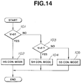
- Fig. 14 shows an operational flowchart for explaining the content of the damping force characteristic control operation for each shock absorber SA executed in the control unit 4.
- the routine goes to a step 104 in which the damping force characteristic of the corresponding one of the shock absorbers SA is set to as the compression phase hard region SH.
- the routine goes to a step 105, namely, if the CPU 4b determines that the value of the control signal V gives zero, the corresponding one of the shock absorbers SA is set to as each of the respective extension and compression phases being in the soft region SS.
- Fig. 15A through 15E show integrally a timing chart for explaining the operation of the control unit 4 and shock absorber(s) SA in the case of the first embodiment.
- each shock absorber SA is controlled in the soft region SS. That is to say, each shock absorber SA, at this time, is controlled in the SS mode in which both of the extension phase and compression phase exhibit the predetermined fixed low damping force characteristics.
- the corresponding one of the shock absorbers SA is controlled so that the extension phase hard region HS is provided and the compression phase is fixed at a predetermined low (soft) damping force characteristic.
- the damping force characteristic at the extension phase is increased to provide a target damping force characteristic position P T in proportion to the magnitude of the control signal V .
- the compression phase hard region SH is provided so that the extension phase damping force characteristic is fixed to the low predetermined damping force characteristic and the damping force characteristic at the compression phase is varied to provide a target damping force characteristic position P C in proportion to the value of the control signal V.
- a symbol a of Fig. 15C denotes a region in which the direction of the control signal V formed on the basis of the sprung mass vertical velocity ⁇ x and relative velocity ( ⁇ x - ⁇ x 0) is inverted from the negative value (downward) to the positive value (upward).
- the relative velocity ( ⁇ x - ⁇ x 0) still provides the negative value (the phase of the shock absorber SA is at the compression phase) so that the corresponding shock absorber SA is controlled at the extension phase hard region HS on the basis of the direction of the control signal V and the phase of the corresponding shock absorber SA is at the extension phase.
- the extension phase from which the piston 31 of the shock absorber SA is moved away provides the hard characteristic which is proportional to the value of the control signal V.
- a region b denotes a region in which the direction (direction discriminating sign) of the control signal V is still positive (upward value) and the relative velocity ( ⁇ x - ⁇ x 0) is switched from the negative value to the positive value (the phase with respect to the piston of the corresponding shock absorber SA is the extension phase).
- the shock absorber SA is controlled in the mode of the extension phase hard region HS on the basis of the direction of the control signal V, the stroke direction of the corresponding shock absorber SA is the extension phase.
- the extension phase side of the shock absorber SA provides the hard characteristic proportional to the value of the control signal V.
- a region c denotes a region in which the control signal V is inverted from the positive value (upward) to the negative value (downward) and the relative velocity ( ⁇ x - ⁇ x 0) still indicates positive (the phase of the corresponding one of the shock absorbers SA is extension phase).
- this region c since the corresponding shock absorber SA is controlled to the compression phase hard region SH on the basis of the direction (direction discriminating sign) of the control signal V, this region c provides the phase (in this region c, the extension phase is provided with the soft (predetermined low damping force) characteristic.
- a region d denotes a region in which the control signal V is still at the negative value (downward) and the relative velocity ( ⁇ x - ⁇ x 0) is changed from the positive value to the negative value (the phase at which the piston of the corresponding shock absorber SA is at the extension phase side).
- the corresponding shock absorber SA is controlled at the compression phase hard region SH on the basis of the direction of the control signal. Hence, the stroke (phase) of the corresponding shock absorber SA is at the compression phase.
- the compression phase provides the hard characteristic proportional to the value of the control signal V.
- the damping force characteristic position P T or P C at the phase to which the control is switched has already been switched to the hard characteristic side at the previous regions a and c. Consequently, the switching from the soft characteristic to the hard characteristic has been carried out without delay in time.
- Fig. 13 shows the configuration of the signal processing circuit for forming the control signal V and for deriving the target damping force characteristic position P based on the control signal.
- velocity converting filters including two first-order low pass filters LPF (L.P.F.) (dotted lines of Figs. 16A and 16B) or two phase advance compensation filters (PCF, or P.C.F.) in the low pass filter types (solid lines of Figs. 16A and 16B) are used to convert the sprung mass vertical accelerations G FL and G FR at the front left and right road wheel positioned parts of the vehicle body into corresponding sprung mass vertical velocities at the front left and right road wheel positioned vehicle body.
- the gain characteristic and phase characteristic of both of each of the first-order low pass filters LPFs and both of each of the phase advance compensation filters PCFs are shown in Figs. 16A and 16B.
- phase advance compensation filters PCFs are used in place of the first-order low pass filters LPFs, the corresponding sprung mass vertical accelerations (G) detected by the sprung mass G sensors 1 FL and 1 FR can be converted into the velocity phases in a relatively wide frequency range.
- the control unit 4 carries out a band pass filtering using two band pass filters (BPFs) in order to cut off the signal components other than a target frequency band to be controlled from the passed sprung mass velocity signals from the first-order low pass filters provided at the block B1.
- BPFs band pass filters
- the two band pass filters BPFs at the block B2 extract the front left and right road wheel positioned sprung mass vertical velocities ⁇ x ( ⁇ x FL , ⁇ x FR ) at the front road wheel positioned vehicle body with a vehicular sprung mass resonance frequency band as a center of target.
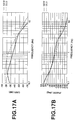
- Figs. 17A and 17B show the gain characteristics (Fig. 17A) and the phase characteristics (Fig. 17B) due to the difference in combinations of the filters at the block B1 and block B2.
- Figs. 17A and 17B denote the gain and phase characteristics when each phase compensation filter PCF and each second-order band pass filter BPF sorely connected to the corresponding one of the phase advance compensation filter PCF are used as the velocity converting filter and the band pass filter BPF at the blocks B1 and B2 (NEW).
- Figs. 17A and 17B denote the gain (Fig. 17A) and phase characteristics (Fig. 17B) of the combination of each first-order low pass filter (LPF) and each first-order band pass filter (BPF) ( connected in series to the corresponding one of the low pass filters LPFs) which are used for the velocity converting filter at the block B1 and for the band pass filter at the block B2 (OLD).
- LPF first-order low pass filter
- BPF band pass filter
- each of the phase advance compensation filters P.C.F. and each of the second-order band pass filters can have a smaller value of gradient in the phase at the target control frequency band, the target control frequency band corresponding to the sprung mass resonance frequency band as compared with the combination of each of the first-order low pass filters and each of the first-order band pass filters.
- each of the band pass filters at the block B2 may comprise the combination (mutually series connected) of a low pass filter and a high-pass filter.
- front road wheel positioned relative velocity signals ( ⁇ x - ⁇ x 0) [( ⁇ x - ⁇ x 0) FL , ( ⁇ x - ⁇ x 0) FR ] at the front left and right road wheel positioned sprung mass and unsprung mass are derived from the front left and right road wheel positioned vertical accelerations G FL and G FR , respectively, using the following transfer function G 5(S) from the sprung mass vertical accelerations at the front left and right road wheel positions detected by the above-described sprung mass vertical acceleration (G) sensors 1 FL and 1 FR .
- Fig. 18 shows an explanatory view of a transfer function calculation model used in the first embodiment.
- x1 denotes a front road wheel side (position) sprung mass input (input variable)
- x2 denotes a front road wheel side (position) sprung mass input (variable)
- x3 denotes a front road wheel side (position) road surface (vibration) input (variable)
- x4 denotes a rear road wheel side (position) sprung mass input (variable)
- m1 denotes a front road wheel side (position) sprung mass
- m2 denotes a front road wheel side (position) unsprung mass
- c1 denotes an attenuation coefficient of a front road wheel side (position) suspension system (constituted by the front left and right road wheel positioned shock absorbers)
- c2 denotes an attenuation coefficient of each one of the front left and right road wheels
- k1 denotes a spring constant of the front road wheel side suspension system
- k2 denotes a spring constant of each of the front road wheels
- x5
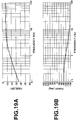
- Figs. 19A and 19B show the gain characteristic and phase characteristic of the above-defined transfer function G 5(S) .
- control signals V FL and V FR used to control the damping force characteristics for the front left and right road wheel positioned shock absorbers SA FL and SA FR are derived using the following equation (2) on the basis of the respective front road wheel positioned sprung mass vertical velocities (signals) ⁇ x ( ⁇ x FL , ⁇ x FR ) derived at the block B2 and the respective relative velocities ( ⁇ x - ⁇ x 0) [( ⁇ x - ⁇ x 0) FL , ( ⁇ x - ⁇ x 0) FR )] between the sprung mass and unsprung mass at the front left and right road wheel positions.
- control unit 4 calculates the target damping force characteristic positions P (P FL , P FR ) in proportion to the corresponding control signals V FL and V FR , respectively, using the following equation (3).
- V (g) ⁇ x/( ⁇ x - ⁇ x 0 ) and (3).
- P (V/V H ) ⁇ P MAX
- V H denotes a threshold value of the proportional control of the damping force characteristic
- P MAX denotes a maximum damping force characteristic position
- a minute threshold value X min is set and when an absolute value of the relative velocity is equal to or below the minute threshold value X min (namely,
- the delay time R is the result of subtraction of a system response delay time ⁇ from the delay transfer function which is derived from the vehicle speed S V and a wheel base length W B and which corresponds to a time delay from the time at which the front road wheel side road surface input x3 occurs to the time at which the rear road wheel side road surface input x 3' occurs.
- the delay time R is set which is the subtraction of the system response delay time ⁇ from the division of W B /S V , the control force for the rear road wheel positioned shock absorbers can be generated with the system response delay canceled.
- the delay processing is carried out before the branched stage of the sprung mass vertical acceleration signals G FR and G FL to the block B1 so that the capacity of memory areas in the memory 4bb used during its programming, namely, the memory capacity of the RAM can be reduced.
- the rear left and right road wheel side (positioned) sprung mass vertical acceleration signals G RL and G RR and the corresponding positioned relative velocity signals ( ⁇ x - ⁇ x 0) RL ( ⁇ x - ⁇ x 0) between the sprung mass and unsprung mass are estimated (calculated) on the basis of the following transfer functions G R(S) and G U(S) from (he front left and right road wheel positioned sprung mass vertical acceleration signals G FL and G FR which are passed through the delay processing at the block B5.
- transfer function calculation model refer to Fig. 18. (4).
- G U(S) G 1(S) X G 2(S) x
- G 1(S) denotes the transfer function from one of the front road wheel positions up to the road surface
- G 2(S) denotes a delay transfer function in a input timing difference between the vehicle body at one of the front road wheel positions and that at one of the rear road wheel positions
- G 3(S) denotes the transfer function from the road surface up to one of the rear road wheel positioned sprung mass
- G 4(S) denotes the transfer function from the road surface up to one of the rear road wheel positioned relative velocities.
- Figs. 20A and 20B show the gain and phase characteristics of the above-described transfer function G R(S) .
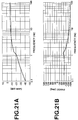
- Figs. 21A and 22B show the gain and phase characteristics of the above-described transfer function G U(S) .
- the velocity converting filters are used at a block B7 to convert the estimated rear left and right road wheel positioned sprung mass acceleration signals G RL and G RR into the corresponding rear left and right road wheel positioned sprung mass vertical velocity signals.
- the band pass filtering operation is carried out for the rear road wheel left and right road wheel positioned vertical velocity signals in order to cut off the frequency components other than the target frequency band to be controlled, in the same way as carried out at the block B2. That is to say, at the block B8, these band pass filters BPFs used at the block B8 serves to extract the rear left and right road wheel positioned sprung mass vertical velocity signals ⁇ x ( ⁇ x RL , ⁇ x RR ) in the vehicle body sprung mass resonance frequency band which is the target of control.
- control signals V RL and V RR for the rear left and right road wheel positioned shock absorbers SA RL and SA RR are formed on the basis of the rear left and right road wheel positioned sprung mass vertical velocity signals ⁇ x ( ⁇ x RL , ⁇ x RR ) derived at the block B8 and on the basis of the rear left and right road wheel positioned relative velocity signals between the sprung mass and unsprung mass ( ⁇ x - ⁇ x 0) [( ⁇ x - ⁇ x0) RL , ( ⁇ x - ⁇ x 0) RR ] using the above-described equation (2) and the target damping force characteristic positions P (P RL , P RR ) for the respective stepping motors 3 for the rear left and right road wheel positioned shock absorbers SA RL and SA RR are calculated using the equation (3) which are proportional to the control signals V RL and V RR .
- the suspension system damping force controlling apparatus in the first embodiment has the following advantages:
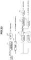
- the velocity converting filters are used to convert the front left and right road wheel position sprung mass vertical acceleration signals G FL and G FR at the front left and right road wheel positions detected by the two front road wheel positioned sprung mass vertical acceleration (G) sensors 1 FL and 1 FR into the corresponding sprung mass vertical velocity signals, respectively, in the same manner as carried out at the block B1 shown in Fig. 13.
- the band pass filters (BPFs) (representatively expressed as BPF in Fig. 23) are used to cut off the frequency components other than the target frequency band to perform the control of the damping force characteristics of the rear left and right road wheel positioned shock absorbers SA RL and SA RR , in the same manner as carried out at the block B2 shown in Fig. 13, so that the sprung mass vertical velocity signals ⁇ x FL and ⁇ x FR at the rear left and right road wheel positions are derived.
- BPFs band pass filters
- the relative velocity signals between the sprung mass and the unsprung mass at the front left and right road wheel positions ( ⁇ x - ⁇ x 0) FL and ( ⁇ x - ⁇ x 0) FR are calculated (estimated) using the transfer function G 5(S) from the respectively corresponding sprung mass vertical accelerations at the front left and right road wheel positions up to the relative velocities between the sprung mass and the unsprung mass at the respectively corresponding front left and right road wheel positions (these are transfer routes) from the signals described below: that is to say, from the front left and right road wheel positioned vertical acceleration signals G FL and G FR detected by the two front road wheel positioned vertical acceleration (G) sensors 1 FL and 1 FR .
- the sprung mass vertical acceleration signals G RL and G RR at the rear left and right road wheel position sprung mass are calculated on the basis of a vertical transfer function G gr(S) with the road surface input as its transfer route shown in the following equation (6) and on the basis of a sprung mass forward/rearward transfer function G gb(S) with the vehicle body sprung mass as its transfer route shown in the following equation (7) from the front left and right road wheel position sprung mass vertical acceleration signals G FL and G FR .
- G gb(S) x 4b(S) /x 1(S)
- G gr1(S) denotes a transfer function from one of the front left and right road wheel position sprung mass vertical accelerations up to the road surface input of one of the front left and right road wheels
- G gr2(S) denotes a transfer function from the road surface input of one of the rear left and right road wheels up to the corresponding one of the rear road wheel position sprung mass vertical accelerations
- x 4r denotes a state variable in the vertical direction at the rear road wheel side transmitted from the corresponding rear road wheel road surface input
- x 4b denotes a state variable in the vertical direction at the rear road wheel side transmitted from the front road wheel side via a transfer route defined in the vehicular forward/rearward (longitudinal) direction (,i.e., front left road wheel side ⁇ rear left road wheel side, front right road wheel side ⁇ rear right road wheel side).
- the velocity converting filters are used to convert the calculated sprung mass vertical acceleration signals G RL and G RR at the rear left and right road wheel positions into the sprung mass vertical velocity signals at the rear left and right road wheel positions, respectively.
- the band pass filters BPF is used to extract the sprung mass vertical velocity signal ⁇ x RL and ⁇ x RR at the rear left and right road wheel positions with the sprung mass resonance frequency band as the target, respectively.
- the relative velocity signals between the sprung mass and the unsprung mass at the rear left and right road wheel positions denoted by ( ⁇ x - ⁇ x0) RL and ( ⁇ x - ⁇ x 0) RR are calculated from the calculated sprung mass vertical acceleration signals G RL and G RR at the rear left and right road wheel positions at the block C4 using a transfer function G rr(S) (G rr(S) is approximately equal to G U(S) ) from each of the rear road wheel sprung mass vertical accelerations up to the relative velocity at the corresponding one of the rear left and right road wheel positions.
- the sprung mass vertical acceleration signals G RL and G RR at the rear left and right road wheel positions are respectively derived from the sprung mass vertical acceleration signals G FL and G FR at the front left and right road wheel positions using the transfer function G gb(S) in the direction of the sprung mass forward/rearward direction with the vehicle body sprung mass as the transfer route thereof in addition to the transfer function G gr(S) in the vertical direction with the road surface input as the transfer route thereof.
- the structure of the signal processing circuit shown in Fig. 24 is generally the same as that in the case of the second embodiment shown in Fig. 23.
- the sprung mass vertical acceleration signals G RL and G RR at the rear left and right road wheel positions are calculated using a sprung mass diagonal direction transfer function G d(S) with the sprung mass as its transfer route as shown in the following equation (9) in addition to the vertical direction transfer function G gr(S) with the road surface input as its transfer route and the sprung mass forward/rearward direction transfer function G gb(S) with the sprung mass as the transfer route thereof (used in the case of the second embodiment).
- Fig. 25 shows the transfer function calculation model in the case of the third embodiment.
- x 1L denotes the state variable of the front left road wheel position sprung mass
- x 1R denotes the state variable of the front right road wheel side sprung mass
- x 4L denotes the state variable of the rear left road wheel position sprung mass caused by the front right road wheel input
- x 4R denotes the state variable of the rear right road wheel position sprung mass caused by the front left road wheel input
- x 4d denotes the state variable of the vertical direction at the rear road wheel positions transmitted from the front road wheel positions via the transfer route in the diagonal direction with respect to the vehicle body (front right road wheel side ⁇ rear left road wheel side and front left road wheel side ⁇ rear right road wheel side) and is derived using the above-described transfer function G d(S) .
- the sprung mass vertical G sensors are installed on the sprung mass at the front left and right road wheel positions
- the number of installations of the sprung mass vertical G sensors are arbitrary.
- the present invention is applicable to the suspension system having a single vertical G (sprung mass vertical acceleration) sensor installed at the front road wheel position, for eXample, a generally center of the front left and right road wheel positions.
- shock absorbers as having the damping force characteristic varying means (adjuster) whose damping force characteristics are controlled such that when the damping force characteristic at either one of the extension and compression phases is variably controlled, the damping force characteristic at the other phase of either of the extension and compression phase is controlled to provide the low damping force characteristic
- the present invention is applicable to a vehicular suspension system having such shock absorbers that the damping force characteristics at both of the extension and compression phases are variably controlled.
- approximation functions or approximation filters such as lower order transfer functions, normally used band pass filters (BPFs) or high pass filters (HPFs) may be used whose gain and phase characteristics are not varied in the frequency band requiring the control of the damping force characteristics of the respective shock absorbers.
- BPFs band pass filters
- HPFs high pass filters
- the control signal may be derived using a correction value KU derived from an inverse of the relative velocity ( ⁇ x - ⁇ x 0) as described in the equation (11) in order to prevent the control signal from being diverged to the infinite.
- a inverse proportional map shown in Fig. 26 may be used.
- KU max denotes a maximum value of KU fixed when the corresponding relative velocity ( ⁇ x - ⁇ x0) is equal to or below a predetermined lower limit threshold value S min .
- S min a predetermined lower limit threshold value
- the correction value KU is fixed at a certain value.
- the above-described equation (3) is used to derive the target damping force characteristic position P from the corresponding control signal V
- a dead zone V NC may be provided for the control signal V in order to prevent the target damping force characteristic position P from being in a hunting phenomenon due to minute upward and downward directional movements of the control signal in the vicinity to zero.
- the gain g of the equation (2) used to derive the control signal V may be varied according to the vehicle speed detected by the vehicle speed sensor 2.
- the signal processing circuit in the control unit 4 described in the first embodiment shown in Fig. 13 is incorporated although the other structures are generally the same as those in the first embodiment.
- each vertical velocity signal ⁇ x is compared with zero.
- the extension phase is varied in the hard damping force characteristic with the compression phase fixed to the soft damping force characteristic, i.e., in the HS control mode.
- ⁇ denotes a constant at the extension phase
- K denotes a gain variably set according to the corresponding sprung mass relative velocity ( ⁇ x - ⁇ x 0).
- the compression phase damping force characteristic is controlled at the hard region with the extension phase characteristic fixed to the soft damping force characteristic.
- ⁇ denotes a compression phase constant
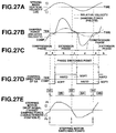
- Figs. 27A through 27E show integrally a timing chart indicating a switching operation of control regions mainly in the representative shock absorber SA from among the damping force characteristic control operations.
- Figs. 27A through 27E the sprung mass vertical velocity ⁇ x is taken as shown in Fig. 27A and the target damping force characteristic position P T at the extension phase of each shock absorber SA (the drive signal for each corresponding one of the stepping motors 3) P T is at the plus side (positive) as shown in Fig. 27E and the target damping force characteristic position at the compression phase of each shock absorber P C (the drive signal for each corresponding one of the stepping motors 3) is at the minus side (negative).
- Figs. 27B, 27C, and 27D are generally the same as those explained in the first embodiment with reference to Figs. 15B, 15C, and 15D, respectively. Therefore the detailed explanations for Figs. 27B, 27C, and 27D are omitted here.
- Kr denotes a gain determined according to each of the rear left and right road wheel position relative velocities between the sprung mass and unsprung mass (( ⁇ x - ⁇ x 0) RL , ( ⁇ x - ⁇ x0) RR ).
- the CPU 4b in the control unit 4 determines whether each of the front road wheel side relative velocities V Rf [( ⁇ x - ⁇ x 0) FL , ( ⁇ x - ⁇ x0) FR exceeds a predetermined threshold value V RD .
- the routine goes to a step 203 in which a correction control flag (Flag) is set to 1. Thereafter, the routine goes to a step 204 in which a counting time of a timer (Time) is reset to zero and, then, at a step 205, the timer is set to ON.
- a correction control flag Flag
- routine goes to a step 206. If NO, namely, each of the front road wheel side relative velocity V Rf is not exceeded the predetermined threshold value V RD , the routine jumps to the step 206.
- the CPU 4b determines whether the correction control flag (Flag) is set to 1. If YES at the step 206, the routine goes to a step 207. If NO at the step 206, the routine goes to a step 211 in which the extension phase target damping force characteristic position P is set to the damping force characteristic position P T at the extension phase at the basic control so that the associated stepping motor 3 is normally controlled.
- the correction control flag Flag
- the CPU 4b determines whether the time of the timer (Time) is below a preset correction control ON time duration TH. If YES at the step 207, namely, Timer ⁇ TH, the routine goes to a step 209 in which the correction control flag Flag is reset to zero and the routine goes to the step 211 to return to the normal basic damping force characteristic control (refer to a time TH4 of Fig. 29).
- the CPU 4b determines whether the damping force characteristic position P T at the extension phase during the basic damping force characteristic control operation is below an extension phase limit position P D set at a predetermined hard characteristic.
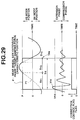
- the routine goes to a step 210 in which the extension phase target damping force characteristic position P for the respective rear road wheel side positioned shock absorbers SA RL and SA RR are set to the respective extension phase limit positions P D so that the corresponding stepping motors 3 can speedily be driven so as to hole the corresponding positions P D (refer to TH1 and TH3 of Fig. 29).
- This is one routine.
- P T ⁇ P0 NO at the step 208, the routine goes to the step 211 in which the target damping force characteristic position P held at the position P D is switched to the damping force characteristic position P T and the associated stepping motor 3 is driven to approach to the target position P T .
- the extension phase target damping force characteristic positions P are set to the extension phase limit positions P D which are the predetermined hard characteristic in the correction control mode.
- the switching control to the extension phase hard control region HS is started. Thereafter, at a time point where the rear road wheels are about to pass the projection by a predetermined delay, the switching to the extension phase hard region HS is already completed or is about to a state where the switching thereto is about to be completed.
- the damping force characteristics at the rear left and right shock absorbers are controlled in proportion to the sprung mass vertical velocities at a time point wherein the rear road wheels pass the projection on the same road surface so that the damping force characteristics at the extension phases are still in the soft characteristics.
- the compression phase soft characteristics at the rear left and right shock absorbers SA RL and SA RR cause the transmission of the road surface input onto the vehicle body to be suppressed without the time delay from a point of time at an initial stage of which the rear road wheels pass the projection on the road surface.
- the extension hard characteristics of the rear left and right road wheel shock absorbers SA RL and SA RR cause the abrupt drop of the unsprung mass to be suppressed without the time delay at the time point wherein the rear road wheels have passed the projection. Consequently, the unsprung mass huntings can be prevented due to the passage of the projection on the road surface.
- the rear road wheel side damping force characteristic control based on the relative velocity signals between the sprung mass and unsprung mass detected and determined at the rear road wheel side cannot achieve the initially desired control effect due to a delay in a control responsive characteristic for the abrupt vehicular behavior when the rear road wheels pass such a projection on the road surface as described above.
- the damping force characteristic positions are expressed in their numerical values so that the numerical values becomes larger as the damping force characteristics at the extension phases give harder characteristics.
- the target damping force characteristic position P T at the time of the basic control is below the extension phase limit position P D .
- the correction control such that the extension hard characteristic is set to the extension phase limit position P D (the step 210 of Fig. 28).
- the target damping force characteristic position P T exceeds the extension phase the extension phase limit position P D
- the target position P is set as the target damping force characteristic position P T (refer to the step 211 of Fig. 28).
- TH W B /(Sv/3.6) + ⁇ t
- W B denotes the wheel base length (meter)
- Sv denotes the vehicle speed (Km/h)
- ⁇ t sec. denotes a constant time from a time at which the vibration input when the front road wheel side relative velocities V Rf at the front road wheel position exceed the predetermined threshold value V RD is inputted to those at the rear road wheel position to a time at which the rear road wheel side unsprung mass huntings are settled ( ⁇ t > 0).
Landscapes
- Engineering & Computer Science (AREA)
- Mechanical Engineering (AREA)
- General Engineering & Computer Science (AREA)
- Vehicle Body Suspensions (AREA)
Applications Claiming Priority (4)
| Application Number | Priority Date | Filing Date | Title |
|---|---|---|---|
| JP245951/94 | 1994-10-12 | ||
| JP24595194A JP3358117B2 (ja) | 1994-10-12 | 1994-10-12 | 車両懸架装置 |
| JP291622/94 | 1994-11-25 | ||
| JP6291622A JPH08142626A (ja) | 1994-11-25 | 1994-11-25 | 車両懸架装置 |
Publications (2)
| Publication Number | Publication Date |
|---|---|
| EP0706906A2 true EP0706906A2 (de) | 1996-04-17 |
| EP0706906A3 EP0706906A3 (de) | 1997-07-02 |
Family
ID=26537493
Family Applications (1)
| Application Number | Title | Priority Date | Filing Date |
|---|---|---|---|
| EP95115893A Withdrawn EP0706906A3 (de) | 1994-10-12 | 1995-10-09 | Verfahren und Vorrichtung zum Steuern der Dämpfungskraft der Radaufhängung eines Fahrzeugs |
Country Status (4)
| Country | Link |
|---|---|
| US (2) | US5794168A (de) |
| EP (1) | EP0706906A3 (de) |
| KR (1) | KR0145228B1 (de) |
| CN (1) | CN1129646A (de) |
Cited By (3)
| Publication number | Priority date | Publication date | Assignee | Title |
|---|---|---|---|---|
| GB2308105A (en) * | 1995-02-14 | 1997-06-18 | Unisia Jecs Corp | Automotive vehicle suspension control system |
| GB2297952B (en) * | 1995-02-14 | 1997-09-03 | Unisia Jecs Corp | Automotive vehicle suspension control system |
| EP2484547A4 (de) * | 2009-09-30 | 2017-09-13 | Mitsubishi Nichiyu Forklift Co., Ltd. | Vorrichtung zur steuerung eines elektrofahrzeugs sowie elektrofahrzeug und gabelstapler damit |
Families Citing this family (40)
| Publication number | Priority date | Publication date | Assignee | Title |
|---|---|---|---|---|
| JP3098425B2 (ja) * | 1996-05-22 | 2000-10-16 | 株式会社豊田中央研究所 | 車両のばね上ばね下相対速度算出装置 |
| JPH10278529A (ja) * | 1997-04-08 | 1998-10-20 | Unisia Jecs Corp | 車両懸架装置 |
| WO2000027659A1 (en) * | 1998-11-11 | 2000-05-18 | Kenmar Company Trust | Enhanced computer optimized adaptive air spring suspension |
| US6115658A (en) * | 1999-01-04 | 2000-09-05 | Lord Corporation | No-jerk semi-active skyhook control method and apparatus |
| US6233510B1 (en) * | 1999-10-15 | 2001-05-15 | Meritor Heavy Vehicle Technology, Llc | Method and system for predicting road profile |
| US6266586B1 (en) * | 1999-12-08 | 2001-07-24 | Allain Gagnon | Vehicle wheel vibration monitoring system |
| KR100534700B1 (ko) * | 2003-08-13 | 2006-01-09 | 현대자동차주식회사 | 자동차의 서스펜션 및 그 제어방법 |
| KR100715594B1 (ko) * | 2003-10-15 | 2007-05-10 | 주식회사 만도 | 전자제어 현가 장치의 감쇠력 제어 방법 |
| CN100478201C (zh) * | 2004-04-27 | 2009-04-15 | 田纳科自动化操作有限公司 | 半主动车辆悬架系统 |
| KR100993168B1 (ko) * | 2004-11-22 | 2010-11-10 | 주식회사 만도 | 차량의 가변 댐퍼 제어방법 |
| RU2412839C2 (ru) * | 2006-10-19 | 2011-02-27 | Тойота Дзидося Кабусики Кайся | Устройство управления гашением колебаний транспортного средства |
| US8839920B2 (en) | 2008-04-17 | 2014-09-23 | Levant Power Corporation | Hydraulic energy transfer |
| JP2010064590A (ja) * | 2008-09-10 | 2010-03-25 | Hitachi Cable Ltd | 移動体の運動制御用センサシステムおよび運動制御システム |
| JP5246269B2 (ja) * | 2008-12-25 | 2013-07-24 | トヨタ自動車株式会社 | 減衰力制御装置 |
| CA2801334C (en) | 2010-06-03 | 2020-03-10 | Polaris Industries Inc. | Electronic throttle control |
| EP3643918B1 (de) | 2010-06-16 | 2023-08-02 | ClearMotion, Inc. | Integrierter stromerzeugender dämpfer |
| JP5634893B2 (ja) * | 2011-01-21 | 2014-12-03 | 本田技研工業株式会社 | 能動型振動騒音制御装置 |
| US8985594B2 (en) * | 2012-01-11 | 2015-03-24 | Toyota Jidosha Kabushiki Kaisha | Vehicle |
| CN104080629B (zh) * | 2012-01-25 | 2016-06-01 | 日产自动车株式会社 | 车辆的控制装置和车辆的控制方法 |
| US9205717B2 (en) | 2012-11-07 | 2015-12-08 | Polaris Industries Inc. | Vehicle having suspension with continuous damping control |
| JP5648870B2 (ja) * | 2013-01-08 | 2015-01-07 | 株式会社安川電機 | モータ制御装置、モータ制御方法及び機械システム |
| US9702349B2 (en) | 2013-03-15 | 2017-07-11 | ClearMotion, Inc. | Active vehicle suspension system |
| WO2014145018A2 (en) | 2013-03-15 | 2014-09-18 | Levant Power Corporation | Active vehicle suspension improvements |
| US9174508B2 (en) | 2013-03-15 | 2015-11-03 | Levant Power Corporation | Active vehicle suspension |
| US9809078B2 (en) | 2013-03-15 | 2017-11-07 | ClearMotion, Inc. | Multi-path fluid diverter valve |
| EP3825156A1 (de) | 2013-04-23 | 2021-05-26 | ClearMotion, Inc. | Aktive aufhängung mit strukturellem aktuator |
| JP6003931B2 (ja) * | 2014-03-11 | 2016-10-05 | トヨタ自動車株式会社 | 車両状態推定装置、車両制御装置及び車両状態推定方法 |
| US9702424B2 (en) | 2014-10-06 | 2017-07-11 | ClearMotion, Inc. | Hydraulic damper, hydraulic bump-stop and diverter valve |
| CN107406094B (zh) | 2014-10-31 | 2020-04-14 | 北极星工业有限公司 | 用于控制车辆的系统和方法 |
| CN104950667A (zh) * | 2015-03-25 | 2015-09-30 | 华东交通大学 | 一种应用在列车主动悬挂系统上的多速率预测控制方法 |
| JP6245217B2 (ja) * | 2015-05-19 | 2017-12-13 | トヨタ自動車株式会社 | 車両の状態量推定装置 |
| US9452657B1 (en) | 2015-12-22 | 2016-09-27 | Ford Global Technologies, Llc | Height determination for two independently suspended wheels using a height sensor for only one wheel |
| CA3043481C (en) | 2016-11-18 | 2022-07-26 | Polaris Industries Inc. | Vehicle having adjustable suspension |
| US10406884B2 (en) | 2017-06-09 | 2019-09-10 | Polaris Industries Inc. | Adjustable vehicle suspension system |
| US10987987B2 (en) | 2018-11-21 | 2021-04-27 | Polaris Industries Inc. | Vehicle having adjustable compression and rebound damping |
| US12397878B2 (en) | 2020-05-20 | 2025-08-26 | Polaris Industries Inc. | Systems and methods of adjustable suspensions for off-road recreational vehicles |
| MX2022015902A (es) | 2020-07-17 | 2023-01-24 | Polaris Inc | Suspensiones ajustables y operacion de vehiculo para vehiculos recreativos todoterreno. |
| JP7281498B2 (ja) * | 2021-03-22 | 2023-05-25 | 本田技研工業株式会社 | 電動サスペンション装置 |
| JP7838540B2 (ja) * | 2023-08-24 | 2026-04-01 | トヨタ自動車株式会社 | サスペンション制御システム |
| CN118494094B (zh) * | 2024-06-19 | 2026-01-13 | 中国第一汽车股份有限公司 | 双阀减振器控制方法、装置、系统、模块和车辆 |
Citations (1)
| Publication number | Priority date | Publication date | Assignee | Title |
|---|---|---|---|---|
| JPH04191109A (ja) | 1990-11-26 | 1992-07-09 | Mitsubishi Motors Corp | 車両用アクティブサスペンション |
Family Cites Families (21)
| Publication number | Priority date | Publication date | Assignee | Title |
|---|---|---|---|---|
| JPS61163011A (ja) * | 1985-01-14 | 1986-07-23 | Nissan Motor Co Ltd | 電子制御ショックアブソ−バ装置 |
| USRE33626E (en) * | 1985-01-16 | 1991-07-02 | Toyota Jidosha Kabushiki Kaisha | Rear suspension controller |
| JP2748546B2 (ja) * | 1989-05-12 | 1998-05-06 | トヨタ自動車株式会社 | 車両振動制御装置 |
| DE3935376A1 (de) * | 1989-10-24 | 1991-04-25 | Bosch Gmbh Robert | Verfahren und vorrichtung zur fahrwerkregelung |
| US5024460A (en) * | 1989-12-26 | 1991-06-18 | General Motors Corporation | Output filter and method for on/off semi-active suspension control |
| JP2937405B2 (ja) * | 1990-04-24 | 1999-08-23 | マツダ株式会社 | 車両のサスペンション装置 |
| JPH0463712A (ja) * | 1990-06-07 | 1992-02-28 | Mazda Motor Corp | 車両のサスペンション装置 |
| US5097419A (en) * | 1990-06-08 | 1992-03-17 | Monroe Auto Equipment Company | Method and apparatus for dynamic leveling |
| JPH04201710A (ja) * | 1990-11-30 | 1992-07-22 | Atsugi Unisia Corp | サスペンション装置 |
| US5235529A (en) * | 1991-05-06 | 1993-08-10 | General Motors Corporation | Real time suspension control with digital all-pass, high-pass filter |
| JPH0550826A (ja) * | 1991-08-19 | 1993-03-02 | Mazda Motor Corp | 車両のサスペンシヨン装置 |
| DE4133666C2 (de) * | 1991-10-11 | 2001-07-05 | Bosch Gmbh Robert | System zur Erzeugung von Signalen zur Steuerung oder Regelung eines in seinen Bewegungsabläufen steuerbaren oder regelbaren Fahrwerkes |
| JP2845029B2 (ja) * | 1992-05-15 | 1999-01-13 | 日産自動車株式会社 | サスペンション制御装置 |
| JPH06247117A (ja) * | 1993-02-23 | 1994-09-06 | Unisia Jecs Corp | 車両懸架装置 |
| JP3182021B2 (ja) * | 1993-03-22 | 2001-07-03 | 株式会社ユニシアジェックス | 車両懸架装置 |
| JP3075501B2 (ja) * | 1993-09-13 | 2000-08-14 | 株式会社ユニシアジェックス | 車両懸架装置 |
| JP3110219B2 (ja) * | 1993-09-13 | 2000-11-20 | 株式会社ユニシアジェックス | 車両懸架装置 |
| EP0659598A1 (de) * | 1993-12-21 | 1995-06-28 | Unisia Jecs Corporation | Vorrichtung und Verfahren zum Regeln der Dämpfungscharakteristiken von Fahrzeugstossdämpfern |
| EP0672548B1 (de) * | 1994-02-24 | 2000-05-31 | Unisia Jecs Corporation | Vorrichtung und Verfahren zum Regeln der Dämpfungscharakteristiken von Fahrzeugstossdämpfern |
| US5510988A (en) * | 1994-12-19 | 1996-04-23 | General Motors Corporation | Vehicle chassis control system |
| US5696677A (en) * | 1995-03-27 | 1997-12-09 | General Motors Corporation | Vehicle chassis control |
-
1995
- 1995-10-09 EP EP95115893A patent/EP0706906A3/de not_active Withdrawn
- 1995-10-10 US US08/541,706 patent/US5794168A/en not_active Expired - Fee Related
- 1995-10-12 KR KR1019950035046A patent/KR0145228B1/ko not_active Expired - Fee Related
- 1995-10-12 CN CN95118281A patent/CN1129646A/zh active Pending
-
1997
- 1997-10-09 US US08/947,854 patent/US5832398A/en not_active Expired - Fee Related
Patent Citations (1)
| Publication number | Priority date | Publication date | Assignee | Title |
|---|---|---|---|---|
| JPH04191109A (ja) | 1990-11-26 | 1992-07-09 | Mitsubishi Motors Corp | 車両用アクティブサスペンション |
Cited By (5)
| Publication number | Priority date | Publication date | Assignee | Title |
|---|---|---|---|---|
| GB2308105A (en) * | 1995-02-14 | 1997-06-18 | Unisia Jecs Corp | Automotive vehicle suspension control system |
| GB2297952B (en) * | 1995-02-14 | 1997-09-03 | Unisia Jecs Corp | Automotive vehicle suspension control system |
| GB2308105B (en) * | 1995-02-14 | 1997-09-03 | Unisia Jecs Corp | Automotive vehicle suspension control system |
| US5802478A (en) * | 1995-02-14 | 1998-09-01 | Unisia Jecs Corporation | Automotive vehicle suspension control system |
| EP2484547A4 (de) * | 2009-09-30 | 2017-09-13 | Mitsubishi Nichiyu Forklift Co., Ltd. | Vorrichtung zur steuerung eines elektrofahrzeugs sowie elektrofahrzeug und gabelstapler damit |
Also Published As
| Publication number | Publication date |
|---|---|
| US5832398A (en) | 1998-11-03 |
| KR0145228B1 (ko) | 1998-08-01 |
| EP0706906A3 (de) | 1997-07-02 |
| KR960013717A (ko) | 1996-05-22 |
| US5794168A (en) | 1998-08-11 |
| CN1129646A (zh) | 1996-08-28 |
Similar Documents
| Publication | Publication Date | Title |
|---|---|---|
| EP0706906A2 (de) | Verfahren und Vorrichtung zum Steuern der Dämpfungskraft der Radaufhängung eines Fahrzeugs | |
| EP0704327A2 (de) | Verfahren und Vorrichtung zum Steuern der Dämpfungskraft der Radaufhängung eines Fahrzeugs | |
| EP0672548B1 (de) | Vorrichtung und Verfahren zum Regeln der Dämpfungscharakteristiken von Fahrzeugstossdämpfern | |
| US5944763A (en) | Control apparatus and method for vehicular suspension system | |
| US6092011A (en) | Apparatus and method for controlling damping force characteristic of vehicular shock absorber | |
| US6067491A (en) | Suspension control system and method for cab over type truck | |
| US5377107A (en) | System and method for controlling damping force characteristic of shock absorber applicable to automotive suspension | |
| EP0752331B1 (de) | Steuerung für eine Radaufhängung eines Kraftfahrzeugs | |
| US5510985A (en) | System for controlling damping force characteristic of shock absorber of vehicle | |
| US5572426A (en) | Apparatus and method for controlling damping force characteristic of vehicular shock absorber | |
| US5515273A (en) | System and method for controlling damping force characteristic of shock absorber of vehicle | |
| US5488556A (en) | Apparatus and method for independently controlling damping force characteristic of vehicular shock absorber | |
| EP0734891B1 (de) | Verfahren und Vorrichtung zum Steuern einer Radaufhängung | |
| US6073066A (en) | Suspension control system and method for cab over type truck | |
| JP2954411B2 (ja) | 車両懸架装置 | |
| JP3069574B2 (ja) | 車両懸架装置 | |
| JP3189685B2 (ja) | 減衰力可変式ショックアブソーバの制御装置 | |
| JP3358117B2 (ja) | 車両懸架装置 | |
| JP3075494B2 (ja) | 車両懸架装置 | |
| JP3016525B2 (ja) | 車両懸架装置 | |
| JP3144712B2 (ja) | 車両懸架装置 | |
| JPH11198624A (ja) | 車両挙動演算装置および車両懸架装置 | |
| JP3144732B2 (ja) | 車両懸架装置 | |
| JPH05286325A (ja) | 車両懸架装置 | |
| JP3066396B2 (ja) | 車両懸架装置 |
Legal Events
| Date | Code | Title | Description |
|---|---|---|---|
| PUAI | Public reference made under article 153(3) epc to a published international application that has entered the european phase |
Free format text: ORIGINAL CODE: 0009012 |
|
| 17P | Request for examination filed |
Effective date: 19951009 |
|
| AK | Designated contracting states |
Kind code of ref document: A2 Designated state(s): DE FR GB |
|
| PUAL | Search report despatched |
Free format text: ORIGINAL CODE: 0009013 |
|
| AK | Designated contracting states |
Kind code of ref document: A3 Designated state(s): DE FR GB |
|
| STAA | Information on the status of an ep patent application or granted ep patent |
Free format text: STATUS: THE APPLICATION IS DEEMED TO BE WITHDRAWN |
|
| 18D | Application deemed to be withdrawn |
Effective date: 20000503 |