EP0679331B1 - Verfahren zum automatischen Melken von Tieren und Vorrichtung zu deren Anwendung - Google Patents
Verfahren zum automatischen Melken von Tieren und Vorrichtung zu deren Anwendung Download PDFInfo
- Publication number
- EP0679331B1 EP0679331B1 EP95200969A EP95200969A EP0679331B1 EP 0679331 B1 EP0679331 B1 EP 0679331B1 EP 95200969 A EP95200969 A EP 95200969A EP 95200969 A EP95200969 A EP 95200969A EP 0679331 B1 EP0679331 B1 EP 0679331B1
- Authority
- EP
- European Patent Office
- Prior art keywords
- milk
- teat
- vacuum
- space
- line
- Prior art date
- Legal status (The legal status is an assumption and is not a legal conclusion. Google has not performed a legal analysis and makes no representation as to the accuracy of the status listed.)
- Expired - Lifetime
Links
- 241001465754 Metazoa Species 0.000 title claims description 27
- 238000000034 method Methods 0.000 title claims description 27
- 210000002445 nipple Anatomy 0.000 claims description 181
- 239000008267 milk Substances 0.000 claims description 125
- 235000013336 milk Nutrition 0.000 claims description 124
- 210000004080 milk Anatomy 0.000 claims description 124
- 239000007788 liquid Substances 0.000 claims description 112
- 230000010349 pulsation Effects 0.000 claims description 66
- XLYOFNOQVPJJNP-UHFFFAOYSA-N water Substances O XLYOFNOQVPJJNP-UHFFFAOYSA-N 0.000 claims description 30
- 238000004140 cleaning Methods 0.000 claims description 20
- 210000003608 fece Anatomy 0.000 claims description 13
- 239000010871 livestock manure Substances 0.000 claims description 13
- 210000000481 breast Anatomy 0.000 claims description 10
- 239000002253 acid Substances 0.000 claims description 8
- 230000000249 desinfective effect Effects 0.000 claims description 6
- 239000000463 material Substances 0.000 claims description 6
- 241000283690 Bos taurus Species 0.000 claims description 5
- 230000004936 stimulating effect Effects 0.000 claims description 5
- 239000012459 cleaning agent Substances 0.000 claims description 4
- ZAMOUSCENKQFHK-UHFFFAOYSA-N Chlorine atom Chemical compound [Cl] ZAMOUSCENKQFHK-UHFFFAOYSA-N 0.000 claims description 3
- 229910052801 chlorine Inorganic materials 0.000 claims description 3
- 239000000460 chlorine Substances 0.000 claims description 3
- 210000000078 claw Anatomy 0.000 claims description 3
- 239000003599 detergent Substances 0.000 claims description 3
- 235000020244 animal milk Nutrition 0.000 claims description 2
- 238000004891 communication Methods 0.000 claims description 2
- 238000005070 sampling Methods 0.000 claims description 2
- 101100327917 Caenorhabditis elegans chup-1 gene Proteins 0.000 description 7
- 239000008237 rinsing water Substances 0.000 description 3
- 238000009835 boiling Methods 0.000 description 2
- 230000002950 deficient Effects 0.000 description 2
- 230000000694 effects Effects 0.000 description 2
- 239000000203 mixture Substances 0.000 description 2
- MFSIEROJJKUHBQ-UHFFFAOYSA-N O.[Cl] Chemical compound O.[Cl] MFSIEROJJKUHBQ-UHFFFAOYSA-N 0.000 description 1
- 238000006073 displacement reaction Methods 0.000 description 1
- 230000007613 environmental effect Effects 0.000 description 1
- 230000000977 initiatory effect Effects 0.000 description 1
- 238000005259 measurement Methods 0.000 description 1
- 108090000623 proteins and genes Proteins 0.000 description 1
- 102000004169 proteins and genes Human genes 0.000 description 1
- 230000000638 stimulation Effects 0.000 description 1
- 239000000126 substance Substances 0.000 description 1
Images


Classifications
-
- A—HUMAN NECESSITIES
- A01—AGRICULTURE; FORESTRY; ANIMAL HUSBANDRY; HUNTING; TRAPPING; FISHING
- A01J—MANUFACTURE OF DAIRY PRODUCTS
- A01J5/00—Milking machines or devices
- A01J5/017—Automatic attaching or detaching of clusters
- A01J5/0175—Attaching of clusters
-
- A—HUMAN NECESSITIES
- A01—AGRICULTURE; FORESTRY; ANIMAL HUSBANDRY; HUNTING; TRAPPING; FISHING
- A01J—MANUFACTURE OF DAIRY PRODUCTS
- A01J5/00—Milking machines or devices
- A01J5/007—Monitoring milking processes; Control or regulation of milking machines
-
- A—HUMAN NECESSITIES
- A01—AGRICULTURE; FORESTRY; ANIMAL HUSBANDRY; HUNTING; TRAPPING; FISHING
- A01J—MANUFACTURE OF DAIRY PRODUCTS
- A01J5/00—Milking machines or devices
- A01J5/007—Monitoring milking processes; Control or regulation of milking machines
- A01J5/0075—Monitoring milking processes; Control or regulation of milking machines with a specially adapted stimulation of the teats
-
- A—HUMAN NECESSITIES
- A01—AGRICULTURE; FORESTRY; ANIMAL HUSBANDRY; HUNTING; TRAPPING; FISHING
- A01J—MANUFACTURE OF DAIRY PRODUCTS
- A01J5/00—Milking machines or devices
- A01J5/04—Milking machines or devices with pneumatic manipulation of teats
- A01J5/08—Teat-cups with two chambers
-
- A—HUMAN NECESSITIES
- A01—AGRICULTURE; FORESTRY; ANIMAL HUSBANDRY; HUNTING; TRAPPING; FISHING
- A01J—MANUFACTURE OF DAIRY PRODUCTS
- A01J7/00—Accessories for milking machines or devices
- A01J7/02—Accessories for milking machines or devices for cleaning or sanitising milking machines or devices
- A01J7/025—Teat cup cleaning, e.g. by rinse jetters or nozzles
-
- A—HUMAN NECESSITIES
- A01—AGRICULTURE; FORESTRY; ANIMAL HUSBANDRY; HUNTING; TRAPPING; FISHING
- A01J—MANUFACTURE OF DAIRY PRODUCTS
- A01J7/00—Accessories for milking machines or devices
- A01J7/04—Accessories for milking machines or devices for treatment of udders or teats, e.g. for cleaning
Definitions
- the present invention relates to a method and implement of automatically milking animals, such as cows, in which use is made of teat cups, each of which is provided with a liner made of a flexible material, by means of which the teat space of a teat cup is separated from the pulsation space that is provided to create therein a pulsating vacuum stimulating the milk yield.
- teat cups each of which is provided with a liner made of a flexible material
- the method according to the invention is characterized in that, when a teat cup is being disconnected, in the pulsation space a fixed vacuum is maintained and in the teat space the vacuum is neutralized, and when a teat cup is being connected to a teat, the pulsation space is kept at an approximately atmospheric pressure, while air is extracted from the teat space.
- connecting a teat cup it applies that, as soon as a predetermined vacuum has been detected in a teat space or in a milk line being in communication with this space, or after a predetermined period of time has elapsed, the approximately atmospheric pressure in the pulsation space is replaced by a pulsating vacuum, whereat the teat cup is capable of further embracing the teat.
- the pulsating vacuum in the pulsation space is replaced by a fixed vacuum which is maintained until at least the vacuum existing in the teat space has been removed.
- the pressure in the pulsation space can be controlled by means of a pulsator under electronic or computer control. Especially when the teat cups are simultaneously connected and disconnected, a single pulsator will be sufficient.
- each teat cup goes with a pulsator of its own. Because the pressure in the pulsation space is kept at a constant value during connection and disconnection, whereas use is made of an alternating vacuum in the pulsation space during milking, it is important that the suction stroke and/or idle stroke and/or the vacuum level of a pulsator is controllable by electronic or computer means.
- a rinsing circuit which includes the teat cups, the milk line and the milk jar, with a rinsing liquid being sucked through the teat cups via separate rinse jetters by the vacuum provided in the milk jar.
- the supply of rinsing liquid through the teat cups can vary to a large extent, which is felt to be disadvantageous.
- this problem is solvable by releasing and closing the rinsing liquid supply lines of the individual rinse jetters either directly by a computer or by means of an electronically controlled or computer-controlled pulsator.
- pre-rinsing by means of water of approximately 32° C to 42° C, especially of about 37° C, can take place in the rinsing circuit. At this temperature, fatty materials in the milk residues present in the various parts of the milking implement can be removed, while the proteins in these milk residues are prevented from solidifying.
- the rinsing circuit may be closed, while therein hot water containing a detergent or cleaning agent is fed, i.e. through the circuit comprising the teat cups, the milk lines connected thereto and a collecting element, such as a milk jar, into which these milk lines discharge.
- the water temperature is then preferably between 20° C and 70° C, and more particularly between 40° C and 50° C.
- the rinsing liquid is drawn in from a rinsing liquid tank by the vacuum applied in the milk jar, and it is pumped back therefrom into the rinsing liquid tank again.
- the rinsing circuit there may be included one or a plurality of temperature sensors, by means of which, using a computer and an adjustable hot-water supply or a heater element in the tank from which the rinsing liquid is put into circulation, the rinsing liquid temperature is kept constant at least during rinsing.
- the rinsing circuit may be open, while therein during a certain time, preferably in the order of two or five minutes, hot water or steam is fed, i.e. through the circuit comprising the teat cups, the milk lines connected thereto and a collecting element, such as a milk jar, into which these milk lines discharge.
- water having a temperature which is between 70° C and 100° C, and preferably more than 80° C can then be led from e.g. a water heater, through the rinsing circuit which includes the milking apparatus, to the sewer.
- the invention also relates to an implement for automatically milking animals, such as cows, in which the method as set forth hereinbefore can be applied.
- the implement is provided with teat cups and a collecting element, such as a milk claw or a milk jar, into which the milk obtained from each udder quarter is fed via separate milk lines, while also each of the teat cups is provided with a liner made of a flexible material, by means of which the teat space of a teat cup is separated from the pulsation space provided to apply therein a pulsating vacuum stimulating the milk yield.
- the implement is then characterized in that for each teat cup there is provided an electronically controlled or computer-controlled pulsator to control the pressure in the pulsation space of a relevant teat cup, such that, when a teat cup is being disconnected, in the pulsation space a vacuum is maintained and in the teat space the vacuum is neutralized, and, when a teat cup is being connected to a teat, the pulsation space is kept at an approximately atmospheric pressure, while air is extracted from the teat space.
- an electronically controlled or computer-controlled pulsator to control the pressure in the pulsation space of a relevant teat cup, such that, when a teat cup is being disconnected, in the pulsation space a vacuum is maintained and in the teat space the vacuum is neutralized, and, when a teat cup is being connected to a teat, the pulsation space is kept at an approximately atmospheric pressure, while air is extracted from the teat space.
- a vacuum sensor whose output signals are supplied to a computer which, as soon as a predetermined vacuum detected by the vacuum sensor has been found in the milk line, causes the approximately atmospheric pressure in the pulsation space to be replaced by a pulsation vacuum.
- a flow sensor whose output signals are supplied to a computer which, as soon as the milk flow obtained has fallen to below a predetermined value detected by the flow sensor, causes the pulsating vacuum in the pulsation space to be replaced by a fixed vacuum which is maintained until at least the vacuum in the teat space has been removed.
- the implement further comprises a rinsing circuit including rinse jetters, which circuit permits at least the teat cups to be included, while each of the rinsing liquid supply lines of the individual rinse jetters is provided with a shut-off element which is operated directly by the computer or is operated by means of a pulsator under electronic or computer control, with the rinsing liquid flow being led through the teat cups by means of said shut-off elements.
- each shut-off element When there is provided a separate pulsator for each teat cup, each shut-off element will consequently be operated by one of these pulsators, while the computer control of the pulsators sees to it that the system of shut-off elements successively opens and closes the rinsing liquid supply line to the individual rinse jetters.
- the vacuum in the teat space or in the milk line connected thereto can be measured permanently by means of vacuum sensors included in the individual milk lines, with the vacuum sensor output signals being supplied to the computer which ensures that the pressure in the milk lines is kept constant by means of a computer-controlled shut-off element in each of the milk lines.
- a particularly advantageous embodiment of the implement for automatically milking is obtained when it is also provided with a milking robot for both automatically connecting the teat cups to an animal's teats and for automatically disconnecting same therefrom.
- the rinsing circuit comprises a first supply line for a pre-rinsing liquid and a second supply line for a further rinsing liquid from the rinsing liquid tank, said first and second supply lines being connected to a rinsing line of the rinsing circuit.
- the invention also relates to an implement for automatically milking animals, such as cows, in which the method as set forth hereinbefore can be applied, which implement is provided with teat cups and a collecting element, such as a milk claw or a milk jar, into which the milk obtained from each udder quarter is fed via milk lines, as well as a rinsing circuit for cleaning at least the teat cups, the collecting element and the milk lines, and a rinsing liquid tank and rinsing lines, this implement being characterized in that the rinsing circuit comprises a first supply line for a pre-rinsing liquid and a second supply line for a further rinsing liquid from the rinsing liquid tank, said first and second supply lines being connected to a rinsing line of the rinsing circuit.
- the rinsing liquid tank can be filled with pre-rinsing liquid prior to, or during cleaning, while subsequently the rinsing liquid can be warmed up to a temperature of between 70° C and 100° C for hot-cleaning.
- the temperature-control means for the pre-rinsing liquid of the first supply line comprise a thermostat with a supply line for hot and cold water.
- the thermostat can be designed as a mixing tap which is adjustable by means of an operator and/or a computer, the arrangement being such that pre-rinsing takes place by water of approximately 37° C.
- the temperature-control means for the second supply line comprise a heater element and a thermostat.
- the rinsing circuit can be supplied with (pre-)rinsing liquid via the first or via the second supply line, because the first supply line and the second supply line are provided with computer-controlled cocks.
- the rinsing liquid tank comprises a sensor to determine the level of the rinsing liquid in the rinsing liquid tank.
- a supply line suitable for supplying a base and/or an acid to the rinsing liquid tank is provided, the supply line comprising a computer-controlled cock.
- the supply line(s) for base and/or acid is/are provided with (a) Venturi element(s).
- a Venturi element in relation to e.g. a displacement pump is that a Venturi element is inexpensive and does not comprise any moving parts which, as is the case with a pump, are liable to wear, which causes that, by comparison with a Venturi element, a pump is less reliable than a Venturi element.
- a rinsing liquid supply line is connected to the first supply line for the supply of rinsing liquid to a cleaning implement for cleaning of cleaning elements, with the aid of which the udder and/or teats of an animal are cleaned, while further in the rinsing liquid line there is included a Venturi element connected, via a further line, to a tank containing a disinfecting liquid, such as chlorine.
- a computer-controlled cock included in the further line whether or not a disinfecting liquid is added to the rinsing liquid.
- the Venturi element is adjustable, the arrangement being such that the flow rate of the line connected to the Venturi element is controllable.
- a pulsating vacuum is mostly simultaneously applied to the pulsation space of the teat cup through a pulsation line and a pulsator.
- the pulsation line becomes leaky due to e.g. wear or kicking by the animal, or in the worst case, when it gets loose from the teat cup and may come into contact with the floor of the cow-shed, it is possible that, because a vacuum still exists in the pulsation line, dirt, such as manure, present on the floor is sucked into the vacuum circuit via the pulsation line.
- a manure separator is included in the pulsation line.
- the manure separator is included and disposed before the pulsator(s), so that the pulsator(s) is/are not in direct danger of being clogged.
- a manure separator is included in each of the four pulsation lines.
- the manure separator comprises a vessel to which the pulsation line, interrupted by the vessel, is connected at the top. Vacuum exists in the vessel just like in the pulsation line, so that manure possibly sucked in through one part of the pulsation line falls into the vessel and, consequently, does not arrive at the other part of the pulsation line.
- the vessel should be exchanged or cleaned after a certain time lapse.
- a milk-level sensor is provided in the milk jar, while near the bottom thereof an air line is connected thereto, by means of which air line it is possible to blow air bubbles through the milk collected in the milk jar in order that the milk is appropriately mixed, while there is provided a milk sampling apparatus connected to the milk discharge line of the milk jar, by means of which apparatus one or a plurality of milk samples can be drawn from a quantity of milk pre-defined by means of the milk-level sensor, so that each milk sample comprises roughly the same quantity of milk, irrespective of the animal's milk yield.
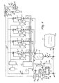
- the teat cups are indicated by the reference number 1. These teat cups are each provided with a liner made of a flexible material, by means of which the teat space of a teat cup is separated from the pulsation space.
- the teat cups 1 are capable of being automatically connected to, and disconnected from an animal's teats by means of a (non-shown) milking robot.
- a milk line 2 is connected to the teat space of each of the teat cups 1. All these milk lines 2 discharge into a milk jar 3.
- the milk jar 3 communicates with a milk tank 7 through a cock 4, a pump 5 and a cock 6.
- each teat cup 1 there is provided a pulsator 8, which produces a milk-yield stimulating, pulsating vacuum in the pulsation space of the respective teat cup 1 during milking.
- Each of the pulsators 8 is connected to a vacuum balance tank 9, wherein a stabilized vacuum is generated by means of a motor-driven pump 10.
- a shut-off element 11 In each of the milk lines 2 connected to the teat cups 1 there is included a shut-off element 11, a vacuum sensor 12 and a flow sensor 13 in that order.
- the implement further comprises a computer 14, by means of which the various parts of the implement for automatic milking are controlled, while it should be specially mentioned that the pulsators 8 are under electronic or computer control, and the sensors 12 and 13 send their acquired information concerning the vacuum or the milk flow in the respective lines to the computer 14.
- the suction stroke, the idle stroke and the vacuum level of the pulsators 8 are computer-controllable. This means that the parameters relevant to the milking, i.e. the pulsation rate, the pulsation ratio and the vacuum level are computer-controlled and attunable to the milk yield from the individual udder quarters of each animal.
- shut-off elements 11 When the teat cups are to be connected, a vacuum is created in the milk jar 3 by means of the vacuum balance tank 9 and, consequently, air is sucked in through the teat space of the respective teat cups and milk lines, of course, insofar as these have been released by the shut-off elements 11.
- the shut-off elements 11 When the teat cups are being connected simultaneously, then the shut-off elements 11 will release the respective milk lines simultaneously; when, however, the teat cups are being connected successively, then the shut-off elements 11 will also release the respective milk lines successively.
- the pulsation frequency can be higher than during a further stage of the milking.
- the flow sensor 13 will issue a signal to the computer 14 which then effects that the pulsator 8 replaces the pulsating vacuum in the pulsation space of the teat cup 1 by a fixed vacuum, so that the liner of the teat cup 1 is sucked against the wall of the teat cup.
- This fixed vacuum will then be of the same magnitude or somewhat less than the vacuum in the milk line 2.
- the vacuum in the teat space can subsequently be removed and the teat cup be disconnected.
- Such a difference in pressure is created across the liner of the teat cups, through the computer-controlled pressure in the pulsation space relative to the pressure in the teat space, that the wear of this liner is restricted considerably.
- the pulsators 8 can also fulfil a function during the rinsing of the teat cups 1.
- the implement is provided with a rinsing circuit 15 comprising a rinsing liquid tank 16, a common rinsing liquid supply line 17, separate rinsing liquid supply lines 18 each being connected to the common rinsing liquid supply line 17, and, connected to the individual rinsing liquid supply lines 18, rinse jetters 19 to which the teat cups 1 can be connected.
- the milk jar 3 is capable of being connected to the rinsing liquid tank 16 again through the cock 6 and a return line 20.
- a "shortened" rinsing circuit through the milk jar 3 can be realized directly by means of the rinsing liquid line 21.
- a heater element 22 in the rinsing liquid tank 16 water of preferably between 40 and 50° C and containing a detergent or cleaning agent can be sucked in, by the vacuum existing in the milk jar 3, via the common rinsing liquid supply line 17, the individual rinsing liquid supply lines 18, the rinse jetters 19, the teat cups 1 and the milk lines 2.
- This rinsing liquid is pumped back again to the rinsing liquid tank 16 via the cock 4, the pump 5, and the cock 6.
- a shut-off element 23 is included in each of the rinsing liquid supply lines 18.
- Each shut-off element 23 is under the control of a pulsator 8.
- the pulsators 8 can be controlled by the computer 14 such that the shut-off elements 23 connected to the respective pulsators successively release and close the rinsing liquid supply lines 18 so as to lead the rinsing liquid successively in time through the respective teat cups 1.
- an open rinsing circuit can also be utilized.
- the temperature of the rinsing liquid is kept as constant as possible during rinsing.
- temperature sensors 24 and 25 are included in the rinsing circuit 15. These temperature sensors communicate with the computer 14, which in its turn controls the heater element 22 in the rinsing liquid tank 16.
- the drawing includes various computer-controlled cocks 26, 27, and 28 (not mentioned before) which are of importance to the initiation and termination of the rinsing of the teat cups, the milk lines and the milk jar and to the draining of the rinsing liquid, either directly or through the rinsing liquid tank 16 to the sewer.
- Figure 2 represents a second exemplary embodiment of the invention, wherein corresponding parts of Figure 1 are indicated by the same reference numbers.
- a first supply line 29 for rinsing liquid such as water
- a computer-controlled cock 30 is included in the first supply line 29.
- the first supply line 29 comprises a thermostatically controlled cock 31, to which a hot-water line 32 and a cold-water line 33 are connected.
- thermostatically controlled cock 31 For pre-rinsing the milk lines, teat cups and milk jar, with the aid of the computer 14 the thermostatically controlled cock 31 is set to a rinsing liquid temperature of between 32° C and 42° C, preferably about 37° C, and the computer-controlled cock 30 is opened for approximately 5 to 7 minutes.
- a second supply line 34 for a further rinsing liquid is connected to the rinsing liquid supply line.
- the second supply line 34 also includes a cock 35 controlled by the computer 14.
- the further rinsing liquid is hot water, which is allowed to flow into the rinsing liquid tank 16 via a line branched off from the hot-water line 32, when the computer-controlled cock 37 included in the line 36 is opened by a signal from the computer 14.
- Connected to the line 36 are also lines 38, permitting a base or an acid to be added to the hot water.
- the lines 38 also include computer-controlled cocks 39.
- the rinsing liquid tank 16 comprises a heater element 22 controlled by a thermostat 40 enabling water to be heated to a temperature of about 78° C, which is a temperature very suitable for hot-cleaning.
- the rinsing liquid tank comprises liquid-level sensors 41, which issue a signal to the computer 14 if no or insufficient water is present in the rinsing liquid tank.
- the rinsing circuit in the vicinity of the milk jar 3 there is also included a temperature sensor 24, with the aid of which the rinsing liquid temperature can be measured, which measurement is issued to the computer 14.
- the temperature sensor 24 is preferably provided at the end of the rinsing circuit, i.e. remotely from the first and second supply lines, so that at the end of the rinsing circuit it can be checked whether the desired and/or minimum temperature of the (pre-)rinsing liquid has been reached there, too. If the minimum temperature has not been reached, in the event of pre-rinsing the computer issues a signal to the thermostatically controlled cock 31, or in the event of main-rin-sing, to the thermostat 40, until the desired minimum temperature of the (pre-)rinsing liquid is obtained.
- the rinsing circuit For the purpose of draining the rinsing liquid into e.g. the sewer, the rinsing circuit comprises two further computer-controlled cocks 42. Possibly infected milk or fore-milk can be discharged into the sewer upon the opening of the computer-controlled cock 6.
- the computer-controlled cock 6 is preferably disposed close by the milk jar 3.
- Figure 3 represents a third exemplary embodiment of the invention, wherein corresponding parts of Figures 1 and 2 are indicated by the same reference numbers.
- the computer-controlled cock 30 is designed as a three-way cock.
- a rinsing liquid line 43 connected to the three-way cock 30 enables rinsing liquid supplied via the first supply line 29 to be applied to a cleaning implement 44 for cleaning of cleaning elements 45, by means of which the udder and/or the teats of an animal are cleaned.
- the cleaning elements 45 are designed as two cleaning rolls 46 disposed at a certain distance from each other and which can be put under the animal's udder by means of a (non-shown) robot. During cleaning, the teats being in between the cleaning rolls 46 driven in mutually opposite directions are rubbed clean.
- a Venturi element 47 is included in the rinsing liquid line 43.
- This Venturi element 47 comprises a cylindrical housing 48 provided with an inlet nipple 49 and an outlet nipple 50.
- the inlet nipple 49 extends in the cylindrical housing 48 as far as the outlet nipple 50 and has a tapered end part 51.
- a tank 54 containing disinfecting liquid, such as chlorine, is connected to the cylindrical housing 48 through a further nipple 52 and a further line 53.
- a computer-controlled cock 55 is included in the further line 53. If it is desired to clean the cleaning elements 45 with a chlorine-water mixture, such a mixture can be obtained by opening the computer-controlled cock 55. Water flowing through the Venturi element 47 makes that in the cylindrical housing 48 there is created a vacuum, as a result of which the disinfecting liquid present in the tank 54 is sucked into the cylindrical housing 48 and is mixed with water.
- the addition of acid or base to the rinsing liquid tank 16 takes place in a similar way as the addition of disinfecting liquid to the rinsing liquid line 43.
- the line 36 branches into a first line 56 and a second line 57, both of which end in the rinsing liquid tank 16.
- a Venturi element 47 In the first line 56 and in the second line 57 there is included a Venturi element 47, while computer-controlled cocks 58 are included in both lines 56 and 57.
- a tank 60 containing a basic liquid is connected to the Venturi element 47 included in the first line 56, while through a line 61, a tank 62 containing an acid is connected to the Venturi element 47 included in the second line 57. Furthermore, computer-controlled cocks 63 are included in the lines 59 and 61.
- Each of the teat cups 1 is also provided with a pulsation line 64, which includes a manure separator 65.
- the manure separator 65 comprises a vessel 66 to which, near the top, interrupted by the vessel 66, the pulsator line 64 is connected.
- the manure separator 65 is disposed in the pulsation line 64 between the teat cup 1 and the pulsator 8.
Landscapes
- Life Sciences & Earth Sciences (AREA)
- Animal Husbandry (AREA)
- Environmental Sciences (AREA)
- Dairy Products (AREA)
- Housing For Livestock And Birds (AREA)
- Cleaning In General (AREA)
- Feeding And Watering For Cattle Raising And Animal Husbandry (AREA)
Claims (40)
- Verfahren zum automatischen Melken von Tieren wie z. B. Kühen, bei dem Zitzenbecher verwendet werden, von denen jeder mit einer Auskleidung aus einem flexiblen Material versehen ist, durch die der Zitzenraum eines Zitzenbechers von dem Pulsierraum getrennt ist, der zum Erzeugen eines pulsierenden Vakuum dient, das den Milchfluß anregt,
dadurch gekennzeichnet, daß beim Abnehmen eines Zitzenbechers in dem Pulsierraum ein gleichbleibendes Vakuum aufrechterhalten wird und in dem Zitzenraum das Vakuum ausgeglichen wird und beim Anschließen eines Zitzenbechers an eine Zitze in dem Pulsierraum ein annähernd atmosphärischer Druck herrscht, während aus dem Zitzenraum Luft abgesaugt wird. - Verfahren nach Anspruch 1,
dadurch gekennzeichnet, daß nach Feststellen eines vorgegebenen Vakuums in einem Zitzenraum oder in einer mit diesem Raum verbundenen Milchleitung oder nach Verstreichen eines vorgegebenen Zeitraumes der annähernd atmosphärische Druck in dem Pulsierraum von einem pulsierenden Vakuum abgelöst wird, wobei der Zitzenbecher die Zitze weiter umschließt. - Verfahren nach Anspruch 1 oder 2,
dadurch gekennzeichnet, daß das pulsierende Vakuum in dem Pulsierraum nach Abfallen des Milchflusses unter einen vorgegebenen Wert von einem gleichbleibenden Vakuum abgelöst wird, das aufrechterhalten wird, bis zumindest das im Zitzenraum herrschende Vakuum beseitigt worden ist. - Verfahren nach einem der vorhergehenden Ansprüche,
dadurch gekennzeichnet, daß während des Anschließens der Zitzenbecher sowie während des Melkens und während des Abnehmens der Zitzenbecher der Druck in dem Pulsierraum mit Hilfe eines elektronisch gesteuerten oder rechnergesteuerten Pulsators gesteuert werden kann. - Verfahren nach einem der vorhergehenden Ansprüche,
dadurch gekennzeichnet, daß die Zitzenbecher einzeln angeschlossen und abgenommen werden, wobei der Druck in dem Pulsierraum jedes Zitzenbechers während des Anschließens der Zitzenbecher an die Zitzen, während des Melkens und während des Abnehmens der Zitzenbecher mit Hilfe von separaten, elektronisch gesteuerten oder rechnergesteuerten Pulsatoren gesteuert wird. - Verfahren nach einem der vorhergehenden Ansprüche,
dadurch gekennzeichnet, daß die Zitzenbecher mit Hilfe eines Melkroboters automatisch an die Zitzen eines Tieres angeschlossen und von ihnen abgenommen werden. - Verfahren nach Anspruch 4 oder 5,
dadurch gekennzeichnet, daß der Ansaugtakt und/oder Leertakt und/oder der Evakuierungsgrad eines Pulsators durch elektronische Vorrichtungen oder einen Computer gesteuert werden. - Verfahren nach Anspruch 7,
dadurch gekennzeichnet, daß das Pulsierverhältnis und/oder die Pulsierfrequenz und/oder der Evakuierungsgrad eines Pulsators für jedes Tier einzeln von einem Computer gesteuert werden. - Verfahren nach einem der vorhergehenden Ansprüche,
dadurch gekennzeichnet, daß während des Melkens das Vakuum in einem Zitzenraum oder in einer mit diesem Raum verbundenen Milchleitung ständig gemessen und mit Hilfe eines Computers auf einem konstanten Wert gehalten wird. - Verfahren nach einem der vorhergehenden Ansprüche,
dadurch gekennzeichnet, daß, wenn zumindest die Zitzenbecher an einen Spülkreislauf angeschlossen sind und über separate Spülflüssigkeits-Sprühvorrichtungen eine Spülflüssigkeit durch die Zitzenbecher geleitet wird, die Spülflüssigkeits-Zuführleitungen der einzelnen Spülflüssigkeits-Sprühvorrichtungen entweder direkt von einem Computer oder mit Hilfe eines elektronisch gesteuerten oder rechnergesteuerten Pulsators geöffnet und geschlossen werden. - Verfahren nach Anspruch 10,
dadurch gekennzeichnet, daß die einzelnen Spülflüssigkeits-Zuführleitungen der Spülflüssigkeits-Sprühvorrichtungen zeitlich nacheinander geöffnet und geschlossen werden. - Verfahren nach Anspruch 10 oder 11,
dadurch gekennzeichnet, daß alle Spülflüssigkeits-Zuführleitungen der Spülflüssigkeits-Sprühvorrichtungen durch separate Pulsatoren geöffnet und geschlossen werden. - Verfahren nach einem der Ansprüche 10 bis 12,
dadurch gekennzeichnet, daß in dem Spülkreislauf mittels Wasser von etwa 32°C bis 42°C, insbesondere von etwa 37°C, ein Vorspülen durchgeführt wird. - Verfahren nach einem der Ansprüche 10 bis 13,
dadurch gekennzeichnet, daß der Spülkreislauf geschlossen wird, wenn warmes Wasser mit einem Waschmittel oder Reinigungsmittel eingeleitet wird, und zwar in den Kreislauf mit den Zitzenbechern, den daran angeschlossenen Milchleitungen und einem Aufnahmeelement, wie z. B. einem Milchgefäß, in das diese Milchleitungen münden. - Verfahren nach Anspruch 14,
dadurch gekennzeichnet, daß die Wassertemperatur 20°C bis 70°C und vorzugsweise 40°C bis 50°C beträgt. - Verfahren nach Anspruch 14 oder 15,
dadurch gekennzeichnet, daß in dem Spülkreislauf ein oder mehrere Temperatursensoren angeordnet ist/sind, mit deren Hilfe unter Verwendung eines Computers und einer einstellbaren Warmwasserzufuhr oder eines Heizelementes in dem Tank, von dem aus die Spülflüssigkeit in Umlauf gebracht wird, die Spülflüssigkeitstemperatur zumindest während des Spülens konstant gehalten wird. - Verfahren nach einem der Ansprüche 10 bis 13,
dadurch gekennzeichnet, daß der Spülkreislauf geöffnet ist, wenn während eines bestimmten Zeitraumes, der vorzugsweise in der Größenordnung von zwei oder fünf Minuten liegt, heißes Wasser oder Dampf eingeleitet wird, und zwar in den Kreislauf mit den Zitzenbechern, den daran angeschlossenen Milchleitungen und einem Aufnahmeelement, wie z. B. einem Milchgefäß, in das diese Milchleitungen münden. - Verfahren nach Anspruch 17,
dadurch gekennzeichnet, daß die Wassertemperatur 70°C bis 100°C und vorzugsweise mehr als 80°C beträgt. - Vorrichtung zum automatischen Melken von Tieren, wie z. B. Kühen, bei der das Verfahren nach einem der vorhergehenden Ansprüche angewendet werden kann, wobei die Vorrichtung mit Zitzenbechern (1) und einem Aufnahmeelement (3), wie z. B. einem Milchsammelstück oder einem Milchgefäß, versehen ist, in das die von jedem Euterviertel eines Tieres gewonnene Milch über separate Milchleitungen (2) eingeleitet wird, wobei auch jeder der Zitzenbecher (1) mit einer Auskleidung aus einem flexiblen Material versehen ist, durch die der Zitzenraum eines Zitzenbechers (1) von dem Pulsierraum getrennt wird, in dem ein den Milchfluß anregendes pulsierendes Vakuum erzeugt wird,
dadurch gekennzeichnet, daß für jeden Zitzenbecher (1) ein elektronisch gesteuerter oder rechnergesteuerter Pulsator (8) vorgesehen ist, um den Druck in dem Pulsierraum eines betreffenden Zitzenbechers (1) zu steuern, so daß beim Abnehmen eines Zitzenbechers in dem Pulsierraum ein gleichbleibendes Vakuum aufrechterhalten wird und in dem Zitzenraum das Vakuum ausgeglichen wird und beim Anschließen eines Zitzenbechers an eine Zitze in dem Pulsierraum ein annähernd atmosphärischer Druck herrscht, während aus dem Zitzenraum Luft abgesaugt wird. - Vorrichtung nach Anspruch 19,
dadurch gekennzeichnet, daß in der an einen Zitzenbecher (1) angeschlossenen Milchleitung ein Vakuumsensor (12) angeordnet ist, dessen Ausgangssignale an einen Computer (14) gegeben werden, der nach Feststellen eines vorgegebenen, von dem Vakuumsensor (12) detektierten Vakuums in der Milchleitung dafür sorgt, daß der annähernd atmosphärische Druck in dem Pulsierraum von einem pulsierenden Vakuum abgelöst wird. - Vorrichtung nach Anspruch 19 oder 20,
dadurch gekennzeichnet, daß in der mit einem Zitzenbecher (1) verbundenen Milchleitung ein Strömungssensor (13) angeordnet ist, dessen Ausgangssignale an einen Computer (14) gegeben werden,
der dafür sorgt, daß nach Abfallen des Milchflusses unter einen vorgegebenen Wert, was von dem Strömungssensor (13) detektiert wird, das pulsierende Vakuum in dem Pulsierraum von einem gleichbleibenden Vakuum abgelöst wird, das aufrechterhalten wird, bis zumindest das im Zitzenraum herrschende Vakuum ausgeglichen worden ist. - Vorrichtung nach einem der Ansprüche 19 bis 21,
dadurch gekennzeichnet, daß die Vorrichtung einen Spülkreislauf (15) mit Spülflüssigkeits-Sprühvorrichtungen (19) umfaßt, wobei zumindest die Zitzenbecher (1) in den Kreislauf integriert werden können, wobei jede der Spülflüssigkeits-Zuführleitungen (18) der einzelnen Spülflüssigkeits-Sprühvorrichtungen (19) mit einem Absperrelement (23) versehen ist, das direkt von dem Computer (14) oder mit Hilfe eines elektronisch gesteuerten oder rechnergesteuerten Pulsators (8) betätigt wird, wobei der Spülflüssigkeitsfluß durch die Zitzenbecher (1) von diesen Absperrelementen (23) gesteuert wird. - Vorrichtung nach einem der Ansprüche 19 bis 22,
dadurch gekennzeichnet, daß während des Melkens das Vakuum in dem Zitzenraum oder in der daran angeschlossenen Milchleitung ständig mit Hilfe von Vakuumsensoren (12) gemessen werden kann, die in den einzelnen Milchleitungen (2) angeordnet sind, wobei die Ausgangssignale des Vakuumsensors (12) an den Computer (14) gegeben werden, der dafür sorgt, daß der Druck in den Milchleitungen mit Hilfe eines rechnergesteuerten Absperrelementes (11) in jeder der Milchleitungen (2) konstant gehalten wird. - Vorrichtung nach einem der Ansprüche 19 bis 23,
dadurch gekennzeichnet, daß sie mit einem Melkroboter zum automatischen Anschließen der Zitzenbecher (1) an eine Tierzitze und zum automatischen Abnehmen derselben von dieser versehen ist. - Vorrichtung nach einem der Ansprüche 19 bis 24,
dadurch gekennzeichnet, daß der Spülkreislauf (15) eine erste Zuführleitung (29) für eine Vorspülflüssigkeit und eine zweite Zuführleitung (34) für eine weitere Spülflüssigkeit aus dem Spülflüssigkeitstank (16) umfaßt, wobei die erste und die zweite Zuführleitung (29, 34) mit einer Spülflüssigkeitsleitung (21) des Spülkreislaufes verbunden sind. - Vorrichtung nach Anspruch 25,
dadurch gekennzeichnet, daß Vorrichtungen (31; 22, 40) zur Temperatursteuerung vorhanden sind, mit deren Hilfe es möglich ist, die Temperatur der Spülflüssigkeit einzustellen, die in die erste und die zweite Zuführleitung (29, 34) eingeleitet wird. - Vorrichtung nach Anspruch 26,
dadurch gekennzeichnet, daß die Temperatursteuerungsvorrichtung für die erste Zuführleitung (29) einen Thermostaten (31) mit einer Warmwasser-Zuführleitung (32) und einer Kaltwasser-Zuführleitung (33) umfaßt. - Vorrichtung nach Anspruch 26 oder 27,
dadurch gekennzeichnet, daß die Temperatursteuerungsvorrichtung (22, 40) für die zweite Zuführleitung (34) ein Heizelement (22) und einen Thermostaten (40) umfaßt. - Vorrichtung nach einem der Ansprüche 25 bis 28,
dadurch gekennzeichnet, daß die erste Zuführleitung (29) und die zweite Zuführleitung (34) mit rechnergesteuerten Hähnen (30, 35) versehen sind. - Vorrichtung nach einem der Ansprüche 25 bis 29,
dadurch gekennzeichnet, daß der Spülflüssigkeitstank (16) mit einem Füllstandssensor (41) für die Spülflüssigkeit versehen ist. - Vorrichtung nach einem der Ansprüche 25 bis 30,
dadurch gekennzeichnet, daß eine Zuführleitung (59, 61) zum Zuführen einer Lauge und/oder einer Säure zu dem Spülflüssigkeitstank (16) vorhanden ist, wobei die Zuführleitung einen rechnergesteuerten Hahn (63) aufweist. - Vorrichtung nach Anspruch 31,
dadurch gekennzeichnet, daß die Zuführleitung(en) (59, 61) für Lauge und/oder Säure mit (einem) Venturielement(en) (47) versehen ist/sind. - Vorrichtung nach einem der Ansprüche 25 bis 32,
dadurch gekennzeichnet, daß eine Spülflüssigkeits-Zuführleitung (43) mit der ersten Zuführleitung (29) zum Zuführen von Spülflüssigkeit zu einer Reinigungsvorrichtung (44) zum Reinigen von Reinigungselementen verbunden ist, mittels derer das Euter und/oder die Zitzen eines Tieres gereinigt werden, wobei ferner in der Spülflüssigkeitsleitung (43) ein Venturielement (47) angeordnet ist, das über eine weitere Leitung (53) mit einem Tank (54) verbunden ist, der eine Desinfektionsflüssigkeit, wie z. B. Chlor, enthält. - Vorrichtung nach Anspruch 33,
dadurch gekennzeichnet, daß ein rechnergesteuerter Hahn (55) in der weiteren Leitung (53) angeordnet ist. - Vorrichtung nach einem der Ansprüche 32 bis 34,
dadurch gekennzeichnet, daß das Venturielement (47) einstellbar ist, wobei die Anordnung so getroffen ist, daß die Strömungsgeschwindigkeit in der mit dem Venturielement (47) verbundenen Leitung steuerbar ist. - Vorrichtung nach einem der vorhergehenden Ansprüche,
dadurch gekennzeichnet, daß ein Dungseparator (65) in der Pulsierleitung (64) angeordnet ist. - Vorrichtung nach Anspruch 36,
dadurch gekennzeichnet, daß der Dungseparator (65) einen Behälter umfaßt, mit dem die Pulsierleitung (64), unterbrochen durch den Behälter, an der Oberseite verbunden ist. - Vorrichtung nach Anspruch 36 oder 37,
dadurch gekennzeichnet, daß ein Dungseparator (65) in jeder der vier Pulsierleitungen (64) angeordnet ist. - Vorrichtung nach einem der Ansprüche 36 bis 38,
dadurch gekennzeichnet, daß der/die Dungseparator(en) (65) vor dem/den Pulsator(en) (8) in der/den Pulsierleitung(en) (64) angeordnet ist/sind. - Vorrichtung nach einem der vorhergehenden Ansprüche,
dadurch gekennzeichnet, daß ein Milchfüllstandssensor in dem Milchgefäß (3) angeordnet ist, wobei nahe dessen Boden eine Luftleitung angeschlossen ist, mittels der Luftblasen in die in dem Milchgefäß (3) gesammelte Milch eingeleitet werden können, um die Milch in geeigneter Weise zu mischen, wobei eine mit der Milchabflußleitung des Milchgefäßes (3) verbundene Milchprobenentnahmevorrichtung vorhanden ist, mittels der eine oder mehrere Milchproben von einer Milchmenge entnommen werden können, die mittels des Milchfüllstandssensors zuvor definiert wurde, so daß jede Milchprobe ungefähr dieselbe Milchmenge aufweist, unabhängig von der Milchleistung des Tieres.
Priority Applications (2)
| Application Number | Priority Date | Filing Date | Title |
|---|---|---|---|
| EP06077043A EP1754411B1 (de) | 1994-04-27 | 1995-04-18 | Verfahren zum automatischen Melken von Tieren und Vorrichtung zu dessen Anwendung |
| EP01204523A EP1186229B1 (de) | 1994-04-27 | 1995-04-18 | Verfahren zum automatischen Melken von Tieren |
Applications Claiming Priority (6)
| Application Number | Priority Date | Filing Date | Title |
|---|---|---|---|
| NL9400675 | 1994-04-27 | ||
| NL9400675 | 1994-04-27 | ||
| NL9401837 | 1994-11-04 | ||
| NL9401837 | 1994-11-04 | ||
| NL9401937 | 1994-11-21 | ||
| NL9401937A NL9401937A (nl) | 1994-04-27 | 1994-11-21 | Werkwijze voor het automatisch melken van dieren en inrichting waarin deze werkwijze kan worden toegepast. |
Related Child Applications (1)
| Application Number | Title | Priority Date | Filing Date |
|---|---|---|---|
| EP01204523A Division EP1186229B1 (de) | 1994-04-27 | 1995-04-18 | Verfahren zum automatischen Melken von Tieren |
Publications (3)
| Publication Number | Publication Date |
|---|---|
| EP0679331A2 EP0679331A2 (de) | 1995-11-02 |
| EP0679331A3 EP0679331A3 (de) | 1995-12-27 |
| EP0679331B1 true EP0679331B1 (de) | 2002-06-26 |
Family
ID=27352456
Family Applications (3)
| Application Number | Title | Priority Date | Filing Date |
|---|---|---|---|
| EP01204523A Revoked EP1186229B1 (de) | 1994-04-27 | 1995-04-18 | Verfahren zum automatischen Melken von Tieren |
| EP95200969A Expired - Lifetime EP0679331B1 (de) | 1994-04-27 | 1995-04-18 | Verfahren zum automatischen Melken von Tieren und Vorrichtung zu deren Anwendung |
| EP06077043A Expired - Lifetime EP1754411B1 (de) | 1994-04-27 | 1995-04-18 | Verfahren zum automatischen Melken von Tieren und Vorrichtung zu dessen Anwendung |
Family Applications Before (1)
| Application Number | Title | Priority Date | Filing Date |
|---|---|---|---|
| EP01204523A Revoked EP1186229B1 (de) | 1994-04-27 | 1995-04-18 | Verfahren zum automatischen Melken von Tieren |
Family Applications After (1)
| Application Number | Title | Priority Date | Filing Date |
|---|---|---|---|
| EP06077043A Expired - Lifetime EP1754411B1 (de) | 1994-04-27 | 1995-04-18 | Verfahren zum automatischen Melken von Tieren und Vorrichtung zu dessen Anwendung |
Country Status (6)
| Country | Link |
|---|---|
| US (2) | US5651329A (de) |
| EP (3) | EP1186229B1 (de) |
| AU (2) | AU694480B2 (de) |
| DE (2) | DE69535420T2 (de) |
| DK (3) | DK1754411T3 (de) |
| NL (1) | NL9401937A (de) |
Cited By (1)
| Publication number | Priority date | Publication date | Assignee | Title |
|---|---|---|---|---|
| WO2014070087A1 (en) | 2012-11-01 | 2014-05-08 | Delaval Holding Ab | Method, computer program, and computer program product for controlling the milking by a milking device, and a milking arrangement |
Families Citing this family (83)
| Publication number | Priority date | Publication date | Assignee | Title |
|---|---|---|---|---|
| NL9400305A (nl) * | 1994-02-28 | 1995-10-02 | Gascoigne Melotte Bv | Inrichting voor het meten van de complexe impedantie van melk, alsmede melkklauw met een dergelijke inrichting. |
| NL9401937A (nl) * | 1994-04-27 | 1995-12-01 | Maasland Nv | Werkwijze voor het automatisch melken van dieren en inrichting waarin deze werkwijze kan worden toegepast. |
| SE9401685D0 (sv) * | 1994-05-17 | 1994-05-17 | Tetra Laval Holdings & Finance | Metod för mjölkning av djur |
| NL9401681A (nl) * | 1994-10-12 | 1996-05-01 | Maasland Nv | Werkwijze en inrichting voor het automatisch melken van dieren, zoals koeien. |
| SE505351C2 (sv) * | 1995-05-17 | 1997-08-11 | Alfa Laval Agri Ab | Sätt att övervaka funktionen hos en mjölkningsmaskin jämte mjölkningsmaskin |
| SE504429C2 (sv) * | 1995-05-17 | 1997-02-10 | Tetra Laval Holdings & Finance | Sätt att styra mjölkning med hjälp av spengummits abrupta rörelse jämte mjölkningsmaskin med avkännare härför |
| EP0797915B2 (de) * | 1996-03-29 | 2005-08-31 | Maasland N.V. | Vorrichtung zum Melken von Tieren |
| JP3382808B2 (ja) * | 1997-02-07 | 2003-03-04 | 株式会社日立ユニシアオートモティブ | 燃料供給装置 |
| NL1006473C2 (nl) * | 1997-07-04 | 1999-01-05 | Maasland Nv | Inrichting voor het automatisch melken van dieren. |
| NL1006586C2 (nl) * | 1997-07-15 | 1999-01-18 | Maasland Nv | Constructie met een inrichting voor het melken van dieren, alsmede een werkwijze daarvoor. |
| NL1007727C2 (nl) * | 1997-12-08 | 1999-06-09 | Maasland Nv | Spoelvloeistofreinigingsinrichting voor het reinigen van althans een deel van een melkmachine. |
| AU744154B2 (en) * | 1997-12-19 | 2002-02-14 | Waikato Milking Systems Nz Limited | Milking machines and use thereof |
| NL1010323C2 (nl) * | 1998-10-15 | 2000-04-18 | Maasland Nv | Werkwijze voor het automatisch melken van dieren en volautomatische melkmachine met een melkrobot geschikt voor het uitvoeren van de werkwijze. |
| DE19900274B4 (de) * | 1999-01-07 | 2009-01-29 | Werner Happel | Verfahren zur Anpassung der Melkanlage an eine Herde von Tieren |
| SE517346C2 (sv) * | 1999-09-15 | 2002-05-28 | Delaval Holding Ab | Mjölkningsanordning med tvätt och sköljning av olika delar och med intervallstyrning |
| SE517344C2 (sv) * | 1999-09-15 | 2002-05-28 | Delaval Holding Ab | Anordning och förfarande för att styra vakuumnivån vid varje spenkopp i beroende av mjölkflödet från respektive spenkopp |
| US6439156B1 (en) * | 2000-11-13 | 2002-08-27 | Dec International, Inc. | Milking vacuum fluctuation filter |
| SE521033C2 (sv) * | 2001-01-12 | 2003-09-23 | Delaval Holding Ab | Förfarande och anordning för att automatiskt mjölka djur samt datorprogram för detta |
| DE10129475B4 (de) * | 2001-06-21 | 2016-11-10 | Gea Farm Technologies Gmbh | Verfahren zum Melken eines Tieres, insbesondere einer Kuh |
| SE520170C2 (sv) * | 2001-09-20 | 2003-06-03 | Delaval Holding Ab | Arrangemang och förfarande för transport av mjölk i en mjölkningsanläggning |
| US7607404B2 (en) | 2001-11-28 | 2009-10-27 | Delaval Holding Ab | Vacuum system communication |
| SE0202988D0 (sv) * | 2002-03-15 | 2002-10-10 | Delaval Holding Ab | A method and an arrangement at a dairy farm |
| US6619227B1 (en) | 2002-04-04 | 2003-09-16 | Danaher Controls | Milking equipment wash monitoring system and method |
| SE0201215D0 (sv) * | 2002-04-23 | 2002-04-23 | Delaval Holding Ab | A device and a method for sampling of milk |
| NL1020782C2 (nl) * | 2002-06-06 | 2003-12-09 | Lely Entpr Ag | Werkwijze en inrichting voor het automatisch melken van een dier. |
| NL1020784C2 (nl) * | 2002-06-06 | 2003-12-09 | Lely Entpr Ag | Inrichting voor het automatisch melken van een dier. |
| NL1020785C2 (nl) * | 2002-06-06 | 2003-12-09 | Lely Entpr Ag | Inrichting voor het melken van dieren. |
| NL1020783C2 (nl) * | 2002-06-06 | 2003-12-09 | Lely Entpr Ag | Werkwijze en inrichting voor het automatisch melken van een dier. |
| US20040069203A1 (en) * | 2002-10-11 | 2004-04-15 | Timothy Fleming | Foam and inflatable collar assemblies for watercraft |
| US6767408B2 (en) * | 2002-12-18 | 2004-07-27 | Hydrite Chemical Co. | Monitoring device and method for operating clean-in-place system |
| US7841296B2 (en) | 2003-02-07 | 2010-11-30 | Global Tech Systems, Inc. | Controller for monitoring and controlling pulsators in a milking system |
| US6990924B2 (en) * | 2003-02-07 | 2006-01-31 | Global Tech Systems Inc | Controller for monitoring and controlling pulsators in a milking system |
| US7051673B2 (en) * | 2003-02-07 | 2006-05-30 | Global Tech Systems, Inc. | Pulsator controller for monitoring and controlling a designated pulsator in a milking system and method of using same |
| SE0301934L (sv) * | 2003-06-30 | 2005-02-22 | Delaval Holding Ab | Mjölkningsanordning och förfarande för hantering av en mjölkningsanordning |
| NL1024295C2 (nl) * | 2003-09-15 | 2005-03-16 | Lely Entpr Ag | Werkwijze voor het melken van een dier en inrichting hiervoor. |
| GB0408968D0 (en) * | 2004-04-22 | 2004-05-26 | Duke James R J | Milking equipment |
| NL1025819C2 (nl) * | 2004-03-26 | 2005-09-27 | Lely Entpr Ag | Werkwijze en inrichting voor het melken van een melkdier. |
| NL1033100C2 (nl) * | 2006-12-21 | 2008-06-24 | Maasland Nv | Melkbekerreinigingsinrichting en -werkwijze. |
| NL1025818C2 (nl) * | 2004-03-26 | 2005-10-03 | Lely Entpr Ag | Inrichting en werkwijze voor het melken van een melkdier. |
| US8540821B2 (en) | 2004-03-26 | 2013-09-24 | Maasland N.V. | Teat cup cleaning device and method |
| US8025029B2 (en) | 2004-06-12 | 2011-09-27 | Gea Farm Technologies, Inc. | Automatic dairy animal milker unit backflusher and teat dip applicator system and method |
| US8342125B2 (en) * | 2004-06-12 | 2013-01-01 | Gea Farm Technologies, Inc. | Safety valve for an automatic dairy animal milker unit backflusher and teat dip applicator |
| US8033247B2 (en) | 2004-06-12 | 2011-10-11 | Gea Farm Technologies, Inc. | Automatic dairy animal milker unit backflusher and teat dip applicator system and method |
| US8117989B2 (en) | 2008-06-27 | 2012-02-21 | Gea Farm Technologies, Inc. | Milk tube dome with flow controller |
| US10874084B2 (en) | 2004-06-12 | 2020-12-29 | Gea Farm Technologies, Inc. | Safety valve for a dairy system component |
| DE102004059089A1 (de) * | 2004-07-15 | 2006-02-02 | Agrar GbR Schmidt & Fenzel (Vertretungsberechtigter Gesellschafter: Herr Jörg Schmidt, 14547 Beelitz) | Melkanlage |
| NL1030474C2 (nl) * | 2005-11-21 | 2007-05-22 | Maasland Nv | Werkwijze voor het stimuleren van de spenen van het uier van een dier, pulsator en werkwijze voor het controleren van het melkproces aan de hand van het pulsatievacuüm. |
| DE102006038484A1 (de) * | 2006-08-16 | 2008-02-21 | Westfaliasurge Gmbh | Verfahren und Vorrichtung zum Desinfizieren von Melkzeug |
| DK1935235T3 (da) * | 2006-12-21 | 2010-05-31 | Maasland Nv | Pattekoprengøringsindretning og fremgangsmåde forbundet dermed |
| SE0800092L (sv) * | 2007-04-13 | 2008-10-14 | Delaval Holding Ab | Optimal tömning av slutenheten under provtagning i vms |
| NL1034963C2 (nl) * | 2007-05-24 | 2008-11-25 | Maasland Nv | Melkbekerreinigingsinrichting en -werkwijze. |
| SE531745C2 (sv) † | 2007-06-01 | 2009-07-28 | Delaval Holding Ab | Förfarande och arrangemang för rengöring av mjölkningssystem med flera mjölkningsstationer |
| SE532738C2 (sv) * | 2008-01-30 | 2010-03-30 | Delaval Holding Ab | Arrangemang och metod vid mjölkprovtagning vid mjölkning av ett djur |
| EP2111750A1 (de) * | 2008-04-25 | 2009-10-28 | Lely Patent N.V. | Verfahren zur Durchführung eines tierbezogenen Vorgangs und Gerät zur Durchführung des Verfahrens |
| NL1035773C2 (nl) * | 2008-07-28 | 2010-01-29 | Lely Patent Nv | Afsluiter voor melkinstallatie. |
| EP2355652B2 (de) * | 2008-11-10 | 2021-03-17 | GEA Farm Technologies GmbH | Verfahren und Vorrichtung zum automatischen inkontaktbringen eines Fluids mit den Zitzen eines Tieres |
| WO2010069811A2 (en) * | 2008-12-18 | 2010-06-24 | Delaval Holding Ab | Diskarrangemang |
| US11723341B2 (en) | 2009-09-04 | 2023-08-15 | Gea Farm Technologies, Inc. | Safety valve for an automated milker unit backflushing and teat dip applicator system |
| US8770146B2 (en) | 2009-09-04 | 2014-07-08 | Gea Farm Technologies, Inc. | Methods and apparatus for applying teat dip to a dairy animal |
| NL1037523C2 (nl) | 2009-12-02 | 2011-06-06 | Lely Patent Nv | Melkinrichting, en werkwijze voor reinigen daarvan. |
| US20120097107A1 (en) | 2010-02-22 | 2012-04-26 | Gea Farm Technologies, Inc. | Dairy animal milking preparation system and methods |
| WO2011102911A2 (en) | 2010-02-22 | 2011-08-25 | Gea Farm Technologies, Inc. | Dairy harvesting facility with milk line protection system an methods |
| EP2632247B1 (de) | 2010-10-26 | 2017-04-26 | DeLaval Holding AB | Steuersystem und verfahren für melkeinheiten eines melkstandes |
| US8671884B2 (en) * | 2011-04-27 | 2014-03-18 | Lanny Gehm | Milking machine attachment aid |
| DK3202257T3 (da) | 2011-04-28 | 2020-07-13 | Technologies Holdings Corp | Malkeboks med mange holdere til patte- eller rengøringskopper |
| DE102011075138A1 (de) | 2011-05-03 | 2012-11-08 | Leibniz-Institut für Agrartechnik Potsdam-Bornim e.V.(ATB) | Verfahren und Kit zum automatischen Melken von Tieren |
| KR101190058B1 (ko) * | 2012-01-19 | 2012-10-12 | 조용석 | 착유기 자동 점검 장치 및 방법 |
| GB201213231D0 (en) | 2012-07-25 | 2012-09-05 | An Udder Company Ltd | Milking equipment |
| DE102013114595B4 (de) | 2013-12-20 | 2026-01-15 | Gea Farm Technologies Gmbh | Sicherheitsventil |
| US9526224B2 (en) | 2013-12-20 | 2016-12-27 | Gea Farm Technologies Gmbh | Safety valve device |
| US20150296736A1 (en) * | 2014-04-17 | 2015-10-22 | Milkline Srl | Method implemented by a computer for the control of milking operations on automated systems |
| NL2012793B1 (nl) * | 2014-05-09 | 2016-02-24 | Lely Patent Nv | Melksysteem. |
| NL2012792B1 (nl) * | 2014-05-09 | 2016-02-24 | Lely Patent Nv | Melkinrichting. |
| NL2012789B1 (nl) | 2014-05-09 | 2016-02-24 | Lely Patent Nv | Melkinrichting. |
| US10258016B2 (en) * | 2014-05-09 | 2019-04-16 | Delaval Holding Ab | Cleaning system and method for an automatic milking system |
| NL2015944B1 (nl) * | 2015-12-11 | 2017-07-05 | Lely Patent Nv | Melkinrichting. |
| DE102016103674A1 (de) * | 2016-03-01 | 2017-09-07 | Gea Farm Technologies Gmbh | Reinigungsverfahren für Melkanlagen und Reinigungsvorrichtung |
| US9901068B2 (en) * | 2016-04-21 | 2018-02-27 | Technologies Holdings Corp. | Solenoid actuated shutoff valve |
| DE102016108300A1 (de) | 2016-05-04 | 2017-11-09 | Gea Farm Technologies Gmbh | Sicherheitsventil |
| US10542723B2 (en) | 2016-07-21 | 2020-01-28 | Lanny Gehm | Milking system |
| EP3703490A1 (de) | 2017-11-03 | 2020-09-09 | GEA Farm Technologies, Inc. | Sicherheitsventilanordnung für ein automatisches melksystem |
| US11825807B2 (en) | 2019-11-08 | 2023-11-28 | Delaval Holding Ab | Milking system |
| WO2023034254A1 (en) * | 2021-08-31 | 2023-03-09 | Gea Farm Technologies, Inc. | Milking system and methods with pre- and post-dip in the teat liner |
Family Cites Families (27)
| Publication number | Priority date | Publication date | Assignee | Title |
|---|---|---|---|---|
| US3479008A (en) * | 1967-06-07 | 1969-11-18 | Zero Manufacturing Co | Self-cleaning valve for vacuum milking system |
| NL7014273A (de) * | 1969-10-06 | 1971-04-08 | ||
| US3696790A (en) * | 1970-01-08 | 1972-10-10 | Zero Manufacturing Co | Teat cup assembly |
| US4011838A (en) * | 1976-03-25 | 1977-03-15 | Alfa-Laval Ab | Electronic milker |
| GB1594087A (en) * | 1977-03-25 | 1981-07-30 | Philips E M | Milking machine pulsator valves |
| US4175514A (en) * | 1977-05-19 | 1979-11-27 | Frank F. Souza, Inc. | Automatic milking machine control and cleansing |
| FR2424700A1 (fr) * | 1978-05-03 | 1979-11-30 | Abrahamson John | Procede et appareil de traite du lait |
| US4222346A (en) * | 1978-11-29 | 1980-09-16 | Reisgies Rolf W | Milk line back flushing method and apparatus |
| US4445522A (en) * | 1982-09-23 | 1984-05-01 | Bender Machine Works, Inc. | Apparatus for cleaning liquid conveying system and control valve assembly therefor |
| EP0131646B1 (de) * | 1983-07-19 | 1989-05-31 | Biomelktechnik Hoefelmayr & Co. | Lufteinlassventil für den Einlass von Luft in die Milchabführleitung eines Melkbechers oder Sammelstücks |
| US4516592A (en) * | 1984-02-29 | 1985-05-14 | Alfa-Laval, Inc. | Milker unit washer |
| US4572105A (en) * | 1984-09-20 | 1986-02-25 | Alfa-Laval, Inc. | Backflushing system |
| FR2595197B1 (fr) * | 1986-03-07 | 1988-11-18 | Cemagref | Installation de traite automatique |
| GB8807999D0 (en) * | 1988-04-06 | 1988-05-05 | Ambic Equip Ltd | Improvements in/relating to automatic milking apparatus |
| DE8809131U1 (de) * | 1988-07-16 | 1988-09-01 | Westfalia Separator Ag, 4740 Oelde | Melkzeug |
| US5272997A (en) * | 1989-02-27 | 1993-12-28 | C. Van Der Lely N.V. | Milking apparatus |
| NL193553C (nl) * | 1989-02-27 | 2003-01-10 | Lely Entpr Ag | Melkinstallatie. |
| US5275124A (en) * | 1989-02-27 | 1994-01-04 | C. Van Der Lely N.V. | Milking apparatus |
| NL9101636A (nl) * | 1991-09-27 | 1993-04-16 | Lely Nv C Van Der | Werkwijze voor het automatisch melken van dieren. |
| US5568788A (en) * | 1990-02-27 | 1996-10-29 | C. Van Der Lely N.V. | Implement for and a method of milking animals automatically |
| DE4113699A1 (de) * | 1991-04-26 | 1992-10-29 | Dieter Dipl Ing Schillingmann | Melkmaschine |
| CA2068834A1 (en) * | 1991-05-17 | 1992-11-18 | Pieter A. Oosterling | Milking cup and a milking set provided with one or more such milking cups and an automatic milking apparatus |
| NL9200258A (nl) * | 1991-10-04 | 1993-05-03 | Lely Nv C Van Der | Werkwijze voor het reinigen van melkbekers en/of het nabehandelen van de spenen van een gemolken dier, inrichting voor het melken van dieren voor het toepassen van deze werkwijze(n), en spoelwerktuig toegepast in een dergelijke inrichting. |
| NL9200091A (nl) * | 1992-01-17 | 1993-08-16 | Lely Nv C Van Der | Melkmachine. |
| US5218924A (en) * | 1992-03-19 | 1993-06-15 | Dec International, Inc. | Milking system with variable pressure source |
| NL9300918A (nl) * | 1993-05-28 | 1994-12-16 | Lely Nv C Van Der | Inrichting voor het melken van dieren. |
| NL9401937A (nl) * | 1994-04-27 | 1995-12-01 | Maasland Nv | Werkwijze voor het automatisch melken van dieren en inrichting waarin deze werkwijze kan worden toegepast. |
-
1994
- 1994-11-21 NL NL9401937A patent/NL9401937A/nl not_active Application Discontinuation
-
1995
- 1995-04-18 DK DK06077043.5T patent/DK1754411T3/da active
- 1995-04-18 EP EP01204523A patent/EP1186229B1/de not_active Revoked
- 1995-04-18 EP EP95200969A patent/EP0679331B1/de not_active Expired - Lifetime
- 1995-04-18 DK DK95200969T patent/DK0679331T3/da active
- 1995-04-18 DE DE69535420T patent/DE69535420T2/de not_active Expired - Lifetime
- 1995-04-18 DE DE69527168T patent/DE69527168T2/de not_active Expired - Lifetime
- 1995-04-18 DK DK01204523T patent/DK1186229T3/da active
- 1995-04-18 EP EP06077043A patent/EP1754411B1/de not_active Expired - Lifetime
- 1995-04-24 AU AU17625/95A patent/AU694480B2/en not_active Ceased
- 1995-04-27 US US08/428,484 patent/US5651329A/en not_active Expired - Lifetime
-
1997
- 1997-04-03 US US08/826,525 patent/US5881669A/en not_active Expired - Lifetime
-
1998
- 1998-07-06 AU AU74175/98A patent/AU713282B2/en not_active Ceased
Cited By (2)
| Publication number | Priority date | Publication date | Assignee | Title |
|---|---|---|---|---|
| WO2014070087A1 (en) | 2012-11-01 | 2014-05-08 | Delaval Holding Ab | Method, computer program, and computer program product for controlling the milking by a milking device, and a milking arrangement |
| US9339003B2 (en) | 2012-11-01 | 2016-05-17 | Delaval Holding Ab | Method, computer program, and computer program product for controlling the milking by a milking device, and a milking arrangement |
Also Published As
| Publication number | Publication date |
|---|---|
| EP1754411B1 (de) | 2011-07-13 |
| EP1186229B1 (de) | 2007-03-07 |
| DE69527168T2 (de) | 2003-02-06 |
| DE69527168D1 (de) | 2002-08-01 |
| DE69535420D1 (de) | 2007-04-19 |
| EP1186229A2 (de) | 2002-03-13 |
| NL9401937A (nl) | 1995-12-01 |
| DE69535420T2 (de) | 2007-11-29 |
| US5881669A (en) | 1999-03-16 |
| EP1186229A3 (de) | 2003-04-23 |
| EP1754411A3 (de) | 2009-03-18 |
| AU713282B2 (en) | 1999-11-25 |
| AU694480B2 (en) | 1998-07-23 |
| AU7417598A (en) | 1998-09-03 |
| EP1754411A2 (de) | 2007-02-21 |
| EP0679331A2 (de) | 1995-11-02 |
| DK0679331T3 (da) | 2002-10-14 |
| EP0679331A3 (de) | 1995-12-27 |
| DK1186229T3 (da) | 2007-07-09 |
| US5651329A (en) | 1997-07-29 |
| AU1762595A (en) | 1995-11-02 |
| DK1754411T3 (da) | 2011-08-15 |
Similar Documents
| Publication | Publication Date | Title |
|---|---|---|
| EP0679331B1 (de) | Verfahren zum automatischen Melken von Tieren und Vorrichtung zu deren Anwendung | |
| EP0944301B1 (de) | Vorrichtung zum automatischen melken von tieren | |
| EP0761091B1 (de) | Verfahren zum Reinigen eines Milchleitungssystem | |
| US5080040A (en) | Milking plant | |
| EP0527509A2 (de) | Verfahren zum Reinigen der Titzen von weiblichen Tieren, Melkverfahren und Melkbecher zur Verwendung bei obengenannten Verfahren | |
| JP3653100B2 (ja) | 動物搾乳装置 | |
| US20020119574A1 (en) | Method and apparatus for cleaning a milk line system | |
| US2915072A (en) | Milk pipe line washing system | |
| AU724419B2 (en) | A method of automatically milking animals and an implement for applying same | |
| EP0666475B1 (de) | Konstruktion zum Melken von Tieren | |
| NL1010827C2 (nl) | Werkwijze en inrichting voor het melken van dieren. |
Legal Events
| Date | Code | Title | Description |
|---|---|---|---|
| PUAI | Public reference made under article 153(3) epc to a published international application that has entered the european phase |
Free format text: ORIGINAL CODE: 0009012 |
|
| AK | Designated contracting states |
Kind code of ref document: A2 Designated state(s): BE DE DK FR GB IT NL SE |
|
| PUAL | Search report despatched |
Free format text: ORIGINAL CODE: 0009013 |
|
| AK | Designated contracting states |
Kind code of ref document: A3 Designated state(s): BE DE DK FR GB IT NL SE |
|
| 17P | Request for examination filed |
Effective date: 19960603 |
|
| 17Q | First examination report despatched |
Effective date: 19990310 |
|
| GRAG | Despatch of communication of intention to grant |
Free format text: ORIGINAL CODE: EPIDOS AGRA |
|
| GRAG | Despatch of communication of intention to grant |
Free format text: ORIGINAL CODE: EPIDOS AGRA |
|
| GRAH | Despatch of communication of intention to grant a patent |
Free format text: ORIGINAL CODE: EPIDOS IGRA |
|
| GRAH | Despatch of communication of intention to grant a patent |
Free format text: ORIGINAL CODE: EPIDOS IGRA |
|
| GRAA | (expected) grant |
Free format text: ORIGINAL CODE: 0009210 |
|
| AK | Designated contracting states |
Kind code of ref document: B1 Designated state(s): BE DE DK FR GB IT NL SE |
|
| PG25 | Lapsed in a contracting state [announced via postgrant information from national office to epo] |
Ref country code: IT Free format text: LAPSE BECAUSE OF FAILURE TO SUBMIT A TRANSLATION OF THE DESCRIPTION OR TO PAY THE FEE WITHIN THE PRESCRIBED TIME-LIMIT;WARNING: LAPSES OF ITALIAN PATENTS WITH EFFECTIVE DATE BEFORE 2007 MAY HAVE OCCURRED AT ANY TIME BEFORE 2007. THE CORRECT EFFECTIVE DATE MAY BE DIFFERENT FROM THE ONE RECORDED. Effective date: 20020626 |
|
| REG | Reference to a national code |
Ref country code: GB Ref legal event code: FG4D |
|
| REF | Corresponds to: |
Ref document number: 69527168 Country of ref document: DE Date of ref document: 20020801 |
|
| REG | Reference to a national code |
Ref country code: DK Ref legal event code: T3 |
|
| ET | Fr: translation filed | ||
| PLBQ | Unpublished change to opponent data |
Free format text: ORIGINAL CODE: EPIDOS OPPO |
|
| PLBI | Opposition filed |
Free format text: ORIGINAL CODE: 0009260 |
|
| PLBF | Reply of patent proprietor to notice(s) of opposition |
Free format text: ORIGINAL CODE: EPIDOS OBSO |
|
| 26 | Opposition filed |
Opponent name: PROLION B.V Effective date: 20030326 |
|
| NLR1 | Nl: opposition has been filed with the epo |
Opponent name: PROLION B.V |
|
| PLBB | Reply of patent proprietor to notice(s) of opposition received |
Free format text: ORIGINAL CODE: EPIDOSNOBS3 |
|
| PLCK | Communication despatched that opposition was rejected |
Free format text: ORIGINAL CODE: EPIDOSNREJ1 |
|
| PLBN | Opposition rejected |
Free format text: ORIGINAL CODE: 0009273 |
|
| STAA | Information on the status of an ep patent application or granted ep patent |
Free format text: STATUS: OPPOSITION REJECTED |
|
| 27O | Opposition rejected |
Effective date: 20051208 |
|
| NLR2 | Nl: decision of opposition |
Effective date: 20051208 |
|
| PGFP | Annual fee paid to national office [announced via postgrant information from national office to epo] |
Ref country code: FR Payment date: 20090417 Year of fee payment: 15 |
|
| PGFP | Annual fee paid to national office [announced via postgrant information from national office to epo] |
Ref country code: BE Payment date: 20090528 Year of fee payment: 15 |
|
| PGFP | Annual fee paid to national office [announced via postgrant information from national office to epo] |
Ref country code: GB Payment date: 20090429 Year of fee payment: 15 |
|
| BERE | Be: lapsed |
Owner name: *MAASLAND N.V. Effective date: 20100430 |
|
| GBPC | Gb: european patent ceased through non-payment of renewal fee |
Effective date: 20100418 |
|
| REG | Reference to a national code |
Ref country code: FR Ref legal event code: ST Effective date: 20101230 |
|
| PG25 | Lapsed in a contracting state [announced via postgrant information from national office to epo] |
Ref country code: GB Free format text: LAPSE BECAUSE OF NON-PAYMENT OF DUE FEES Effective date: 20100418 Ref country code: BE Free format text: LAPSE BECAUSE OF NON-PAYMENT OF DUE FEES Effective date: 20100430 |
|
| PG25 | Lapsed in a contracting state [announced via postgrant information from national office to epo] |
Ref country code: FR Free format text: LAPSE BECAUSE OF NON-PAYMENT OF DUE FEES Effective date: 20100430 |
|
| PGFP | Annual fee paid to national office [announced via postgrant information from national office to epo] |
Ref country code: DK Payment date: 20120425 Year of fee payment: 18 Ref country code: NL Payment date: 20120426 Year of fee payment: 18 |
|
| PGFP | Annual fee paid to national office [announced via postgrant information from national office to epo] |
Ref country code: DE Payment date: 20130429 Year of fee payment: 19 Ref country code: SE Payment date: 20130429 Year of fee payment: 19 |
|
| REG | Reference to a national code |
Ref country code: NL Ref legal event code: V1 Effective date: 20131101 |
|
| REG | Reference to a national code |
Ref country code: DK Ref legal event code: EBP Effective date: 20130430 |
|
| PG25 | Lapsed in a contracting state [announced via postgrant information from national office to epo] |
Ref country code: NL Free format text: LAPSE BECAUSE OF NON-PAYMENT OF DUE FEES Effective date: 20131101 |
|
| PG25 | Lapsed in a contracting state [announced via postgrant information from national office to epo] |
Ref country code: DK Free format text: LAPSE BECAUSE OF NON-PAYMENT OF DUE FEES Effective date: 20130430 |
|
| REG | Reference to a national code |
Ref country code: DE Ref legal event code: R119 Ref document number: 69527168 Country of ref document: DE |
|
| REG | Reference to a national code |
Ref country code: SE Ref legal event code: EUG |
|
| PG25 | Lapsed in a contracting state [announced via postgrant information from national office to epo] |
Ref country code: DE Free format text: LAPSE BECAUSE OF NON-PAYMENT OF DUE FEES Effective date: 20141101 Ref country code: SE Free format text: LAPSE BECAUSE OF NON-PAYMENT OF DUE FEES Effective date: 20140419 |
|
| REG | Reference to a national code |
Ref country code: DE Ref legal event code: R119 Ref document number: 69527168 Country of ref document: DE Effective date: 20141101 |