EP0664984A2 - Differentialauszug für Schubladen - Google Patents
Differentialauszug für Schubladen Download PDFInfo
- Publication number
- EP0664984A2 EP0664984A2 EP94120260A EP94120260A EP0664984A2 EP 0664984 A2 EP0664984 A2 EP 0664984A2 EP 94120260 A EP94120260 A EP 94120260A EP 94120260 A EP94120260 A EP 94120260A EP 0664984 A2 EP0664984 A2 EP 0664984A2
- Authority
- EP
- European Patent Office
- Prior art keywords
- rail
- pull
- differential
- drawer
- fastened
- Prior art date
- Legal status (The legal status is an assumption and is not a legal conclusion. Google has not performed a legal analysis and makes no representation as to the accuracy of the status listed.)
- Granted
Links
- 230000008878 coupling Effects 0.000 claims abstract description 51
- 238000010168 coupling process Methods 0.000 claims abstract description 51
- 238000005859 coupling reaction Methods 0.000 claims abstract description 51
- 230000037431 insertion Effects 0.000 claims abstract description 17
- 238000003780 insertion Methods 0.000 claims abstract description 17
- 235000008331 Pinus X rigitaeda Nutrition 0.000 claims description 3
- 235000011613 Pinus brutia Nutrition 0.000 claims description 3
- 241000018646 Pinus brutia Species 0.000 claims description 3
- 235000004443 Ricinus communis Nutrition 0.000 claims 1
- 240000000528 Ricinus communis Species 0.000 claims 1
- 238000010586 diagram Methods 0.000 description 7
- 230000006835 compression Effects 0.000 description 6
- 238000007906 compression Methods 0.000 description 6
- 239000000463 material Substances 0.000 description 3
- 229910000831 Steel Inorganic materials 0.000 description 2
- 230000000694 effects Effects 0.000 description 2
- 239000010959 steel Substances 0.000 description 2
- 239000006096 absorbing agent Substances 0.000 description 1
- 229910052782 aluminium Inorganic materials 0.000 description 1
- XAGFODPZIPBFFR-UHFFFAOYSA-N aluminium Chemical compound [Al] XAGFODPZIPBFFR-UHFFFAOYSA-N 0.000 description 1
- 238000013016 damping Methods 0.000 description 1
- 229910052751 metal Inorganic materials 0.000 description 1
- 239000002184 metal Substances 0.000 description 1
- 230000035939 shock Effects 0.000 description 1
- 229910001220 stainless steel Inorganic materials 0.000 description 1
- 239000010935 stainless steel Substances 0.000 description 1
- 230000007704 transition Effects 0.000 description 1
Images


Classifications
-
- A—HUMAN NECESSITIES
- A47—FURNITURE; DOMESTIC ARTICLES OR APPLIANCES; COFFEE MILLS; SPICE MILLS; SUCTION CLEANERS IN GENERAL
- A47B—TABLES; DESKS; OFFICE FURNITURE; CABINETS; DRAWERS; GENERAL DETAILS OF FURNITURE
- A47B88/00—Drawers for tables, cabinets or like furniture; Guides for drawers
- A47B88/40—Sliding drawers; Slides or guides therefor
- A47B88/49—Sliding drawers; Slides or guides therefor with double extensible guides or parts
- A47B88/493—Sliding drawers; Slides or guides therefor with double extensible guides or parts with rollers, ball bearings, wheels, or the like
-
- A—HUMAN NECESSITIES
- A47—FURNITURE; DOMESTIC ARTICLES OR APPLIANCES; COFFEE MILLS; SPICE MILLS; SUCTION CLEANERS IN GENERAL
- A47B—TABLES; DESKS; OFFICE FURNITURE; CABINETS; DRAWERS; GENERAL DETAILS OF FURNITURE
- A47B88/00—Drawers for tables, cabinets or like furniture; Guides for drawers
- A47B88/40—Sliding drawers; Slides or guides therefor
- A47B88/453—Actuated drawers
- A47B88/46—Actuated drawers operated by mechanically-stored energy, e.g. by springs
- A47B88/467—Actuated drawers operated by mechanically-stored energy, e.g. by springs self-closing
-
- A—HUMAN NECESSITIES
- A47—FURNITURE; DOMESTIC ARTICLES OR APPLIANCES; COFFEE MILLS; SPICE MILLS; SUCTION CLEANERS IN GENERAL
- A47B—TABLES; DESKS; OFFICE FURNITURE; CABINETS; DRAWERS; GENERAL DETAILS OF FURNITURE
- A47B2210/00—General construction of drawers, guides and guide devices
- A47B2210/0002—Guide construction for drawers
- A47B2210/0064—Guide sequencing or synchronisation
- A47B2210/007—Three slide synchronisation
-
- A—HUMAN NECESSITIES
- A47—FURNITURE; DOMESTIC ARTICLES OR APPLIANCES; COFFEE MILLS; SPICE MILLS; SUCTION CLEANERS IN GENERAL
- A47B—TABLES; DESKS; OFFICE FURNITURE; CABINETS; DRAWERS; GENERAL DETAILS OF FURNITURE
- A47B2210/00—General construction of drawers, guides and guide devices
- A47B2210/0002—Guide construction for drawers
- A47B2210/0064—Guide sequencing or synchronisation
- A47B2210/0072—Coordinating mechanisms for sequential drawer slides, e.g. by cable
-
- A—HUMAN NECESSITIES
- A47—FURNITURE; DOMESTIC ARTICLES OR APPLIANCES; COFFEE MILLS; SPICE MILLS; SUCTION CLEANERS IN GENERAL
- A47B—TABLES; DESKS; OFFICE FURNITURE; CABINETS; DRAWERS; GENERAL DETAILS OF FURNITURE
- A47B2210/00—General construction of drawers, guides and guide devices
- A47B2210/0002—Guide construction for drawers
- A47B2210/0064—Guide sequencing or synchronisation
- A47B2210/0083—Drawer symmetric movement on opposite telescopic rails
-
- A—HUMAN NECESSITIES
- A47—FURNITURE; DOMESTIC ARTICLES OR APPLIANCES; COFFEE MILLS; SPICE MILLS; SUCTION CLEANERS IN GENERAL
- A47B—TABLES; DESKS; OFFICE FURNITURE; CABINETS; DRAWERS; GENERAL DETAILS OF FURNITURE
- A47B2210/00—General construction of drawers, guides and guide devices
- A47B2210/02—Drawers with hollow lateral walls in two parts
Definitions
- the invention relates to a differential pull-out for drawers or the like.
- a mounting rail to be fastened to a furniture body With a mounting rail to be fastened to a furniture body, a pull-out rail to be fastened to the drawer and a middle rail arranged in between on each side of the drawer, the weight of the drawers between the rails by means of rollers od.
- a deflection roller is arranged, and a control cable, which is attached to the mounting rail and on the pull-out rail, is guided over the deflection rollers.
- Various full pull-outs for drawers are known in which the drawer can be completely pulled out of the furniture body and is nevertheless held by the rails of the full pull-out.
- a device is provided to ensure that the rails run differentially with respect to one another.
- This device can consist, for example, of a gearwheel mounted on the central rail, which meshes with toothed racks on the pull-out rail and the mounting rail.
- a simplified version would be the arrangement of a friction wheel on the middle rail.
- a particularly precise guidance of the middle rail is achieved by a control cable which is fastened to the mounting rail and the pull-out rail and which runs on both sides of the middle rail and is guided at the front and rear ends via band guides of the middle rail.
- a control cable which is fastened to the mounting rail and the pull-out rail and which runs on both sides of the middle rail and is guided at the front and rear ends via band guides of the middle rail.
- control cable has two free ends which can be coupled in a manner known per se by a receiving part and an insertion part which have rack-like profiles, the receiving part or the insertion part being able to be coupled to the mounting rail and in that two Further coupling parts which can be coupled to one another via rack-like profiles are provided, one of which is designed as a cable coupling part fastened to the control cable and one as a rail coupling part fastened to the pull-out rail.
- a known pull-in device for the drawer is arranged on the mounting rail or on the pull-out rail, which comprises a spring-loaded driver, which can be moved in a linear guideway and can be locked at the two ends of the guideway and that the central rail has a pin or the like, which the driver engages in the rear entry area of the differential pull-out.
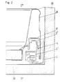
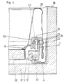
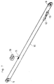
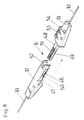
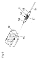
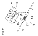
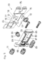
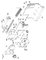
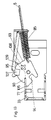
- Fig. 1 shows a diagram and pulled apart the parts of the differential pull-out and the drawer frame; 2 shows a vertical section through one side of the drawer; 3 shows a diagram of the central rail; 4 shows a vertical section through the drawer frame and the differential pull-out in the rear area; 5 shows a diagram of a pull-out rail with adapter; Fig. 6 shows diagrammatically and pulled apart the rear rollers and the rear adapter; 7 shows a diagram of the control cable and the two clutches; 8 shows a diagram of the cable coupling; FIG. 9 shows a diagram of the coupling which connects the control cable to the pull-out rail, the coupling being indicated from the front; FIG. 10 shows the same diagram as FIG.
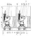
- FIG. 12 shows the same view as FIG. 11 of a further exemplary embodiment of a fastening device for the front panel and FIGS. 13 to 15 show side views of the fastening device according to FIG. 12.
- the drawer is formed by the two metal drawer frames 28 of the front panel 39, the drawer base 38 and the rear wall 27.
- the mounting rail 2 is fastened to the body side wall 36 in the usual manner via a fastening web 40.
- the drawer bottom 38 rests on a horizontal web 41 of the pull-out rail 15.
- In the horizontal web 41 there are tabs 42 with a pinecone profile that can be expressed from the horizontal web 41 and can be pressed into a groove or the like of the drawer base 38 and thus anchor the drawer base 38 on the pull-out rail 15.
- the central rail 5 is located between the pull-out rail 15 and the mounting rail 2.
- the central rail 5 has a lower profile 5 ', in which there is a carriage 3 in which rollers are mounted.
- the middle rail 5 is therefore guided in relation to the mounting rail 2 via the rollers mounted in the carriage 3.
- the middle rail 5 is provided with an upper, partially U-shaped profile 5 ′′.
- the rollers 22, 23, which are mounted on the rear adapter 18 of the pull-out rail 15, run on the catwalks 43, 44 of this profile 5 ′′.
- the catwalk 45 of the pull-out rail 15 runs on the roller 6 mounted on the lower profile 5 'of the central rail 5.
- the central rail 5 has a front and a rear cable pulley 9 for the control cable 10, which is mounted on the cable pulleys 9 of the central rail 5.
- the control cable 10 which is formed, for example, by a wire or plastic cable, has a snap-type cable coupling 8.
- the cable coupling 8 consists of two coupling parts, namely a receiving part 12 and an insertion part 13, which are connected to the cable ends of the control cable 10.
- the receiving part 12 is designed as a housing. It has two rack-like profiles 46 on the inside. The side walls are provided with openings 47, which give the housing of the receiving part 12 a certain elasticity.
- the insertion part 13 has a finger-like projecting web 48, which is also provided with rack-like profiles 49, which correspond to the rack-like profiles 46 of the receiving part 12. The web 48 can be inserted into the housing of the receiving part 12 until the control cable 10 is tensioned.
- the teeth 50, 51 of the rack-like profiles 46, 49 are designed like pine cones and counter to one another in order to facilitate the insertion of the web 48 of the insertion part 13 into the housing of the receiving part 12.
- the receiving part 12 is provided with a U-shaped recess 52.
- the insertion part 13 has a side hook 53 with which it can be inserted into an opening 14 in the mounting rail 2.
- the insertion part 13 can thus be anchored to the mounting rail 2 via the hook 53.
- guide pins 54 are formed on the insertion part 13, which also protrude into the opening 14 and improve the fit of the hook 53 in the opening 14.
- a special coupling is also provided.
- This consists of an outer rail coupling part 19 and an inner cable coupling part 11.
- the outer rail coupling part 19 is fastened to the pull-out rail 15 by means of screws or rivets 20 which protrude through fastening holes. It includes the inner cable coupling part 11 like pliers.
- the inner cable coupling part 11 is torpedo-shaped and can be pressed into a trough-shaped recess 55 of the outer rail coupling part 19.
- a slot-like opening 120 is provided, which widens in a circle at both ends. This increases the elasticity of the rail coupling part 19 made of plastic.
- the rack-like profile 56 On the wall of the trough-shaped recess, two rack-like profiles are provided, which correspond to the rack-like profile 56 of the cable coupling part 11.
- the teeth 57 of the rack-like profile 56 are designed annular.
- the cross section of the teeth 57 is either like a pine cone or the cross section corresponds to an isosceles triangle.
- the teeth 57 can be rounded on the outer edge.
- the cable coupling part 11 is approximately cylindrical or torpedo-shaped and has a frustoconical end section 58 on both sides.
- the rail coupling part 19 In order to connect the coupling parts 11, 19 to one another, the rail coupling part 19, as shown in FIG. 9, can be pushed onto the cable coupling part 11 from the front or, as shown in FIG.
- a roller 6 is mounted on tabs 59 by means of a rent 7.
- the runway 45 of the pull-out rail 15 runs on the roller 6.
- Three adapters 16, 17, 18 are attached to the running rail 15.
- two rollers 22, 23 are supported by rivets 21.
- the rollers 22, 23 are guided in the upper profile 5 ′′ of the middle rail 5 and are located inside the adapter 18. They are mounted one behind the other.
- the front roller 22 is narrower than the rear roller 23 and is supported on the web 43 of the upper profile 5 ′′ of the center rail 5 when the drawer is moved.
- the web 44 of the profile 5 ′′ of the central rail 5 is U-shaped with a lateral limiting web 60. Between this limiting web 60 and the vertical web 61, which runs at the top with the same slope as the limiting web 60, the roller 23 is fed properly. This ensures lateral guidance of the pull-out rail 15 and thus the drawer. Since the roller 22 is supported on the lower horizontal web 43 and the roller 23 on the upper horizontal web 44, there is no change in the direction of rotation of the rollers 22, 23 during pulling out or pushing in of the drawer and thus smooth running of the drawer is achieved.
- a headstock 4 made of plastic material is attached at the front end of the lower profile 5 'of the center rail 5.
- the headstock 4 has an opening 62 in which the roller 6 is mounted.
- the roller 6 is supported on a rivet 7, which is held in flanges 67.
- the headstock 4, which overlaps the front end of the lower profile 5 'of the central rail 5, is provided with a rail web 63 which has a straight section 63' and a front, downwardly bent section 63 ''.
- All three adapters 16, 17, 18 have retaining webs 64 projecting downwards.
- the drawer frames 28 are double-walled with an outer wall 65 and an inner wall 66.
- the outer wall 65 has, at its lower edge, a retaining web 67 which is angled inwards and upward, with which it can be suspended in the retaining webs 64 of the adapters 16, 17, 18.
- the inner wall 66 has a horizontal web 68 which rests on the drawer base 38 when the drawer is mounted and a vertical side web 69 which rests on the side of the drawer base 38.
- the transition from the horizontal web 68 to the inner wall 66 is rounded.
- drawer frame 28 is neither welded or grooved to the adapters 16, 17, 18, nor to the pull-out rail 15, drawer frames made of any material can be hung into the adapters 16, 17, 18, from plastic frames to aluminum frames to steel frames made of a stainless steel material.
- the furniture manufacturer is therefore given the possibility of equipping drawers with very different prices with the differential pull-out according to the invention.
- the foremost adapter 16 is provided with a holding plate 70 to which a supporting part 32, 33 of a fastening device 30, 31 for the front panel 39 can be screwed.
- the front panel 39 is pressed onto the dowels 71 of the front panel fastening 30 when the drawer is assembled.
- the fastening device 30 is fully mounted on the pull-out rail 15.
- a holding part 34 is fastened to the front panel 39 and the supporting part 33 is fastened to the holding plate 70 by means of a screw 72.
- Both the support part 33 of the fastening device 31 and the support part 32 of the fastening device 30 are provided with a lateral guide wall 73 which bears against a corresponding guide wall 74 of the holding plate 70.
- the support part 32 of the fastening device 30 has a slot 75 which is open to the rear and through which the fastening screw 72 projects, which can be screwed into a nut thread 76 in the holding plate 70.
- the fastening device 30 has a holding part 80 which is fastened to the front panel 39 with dowels 71.
- the support part 32 which is stamped from a steel sheet, has a tab 76 which projects at a right angle from the support part 32.
- the support part 32 has a horizontal web 77, each with a slot 78 open to the rear. Pins 79 of the holding part 80 are guided in the slots 78.
- the holding part 80 is provided with a recess 81.
- An adjustment screw 82 for the lateral adjustment of the front panel 39 is also mounted in the holding part 80. When the fitting is mounted, the upper edge 83 of the support part 32 protrudes into an annular groove 84 of the adjusting screw 82, so that the holding part 81 is moved laterally with respect to the supporting part 32 by turning the adjusting screw 82.
- the flange 76 of the supporting part 32 projects into the recess 81 of the holding part 80.
- a compression spring 85 is mounted in the recess 81 and is supported on the one hand on the web 86 of the holding part 80 and on the other hand on the tab 76 of the supporting part 32.
- the holding part 80 is pressed backwards by the compression spring 6 and thus the front panel 39 is drawn to the front edges of the drawer frames 28.
- the drawer If the drawer is pushed into the furniture body with too much momentum, the front panel 39 strikes the front edges of the side walls 36 of the furniture body. However, the drawer can continue to move with the drawer frames 28, the pull-out rails 15 and the supporting parts 32 against the pressure of the compression springs 85 relative to the holding parts 80, so that a damping effect occurs and the hold of the dowels 71 in the front panel 39 is not excessively stressed. If the run-in energy is destroyed, the drawer frames 28 are over the supporting part 32 and the holding plates 70 pressed by the compression springs 85 on the front panel 28.
- the fastening device 30 When assembling the drawer, the fastening device 30 according to the invention is completely mounted in the drawer frame 28.
- the holding part 80 is pressed by the compression spring 85 into the rear end position.
- the outer wall 65 of the front panel 28 is provided in the area of the fastening device 30, 33 with a recess 87, which enables tools to be accessed on the fastening device 30, 33.
- the recess 87 is covered by a removable cover plate 29.
- the holding part 80 is pressed out of the drawer frame 28 somewhat by means of a press ram which engages in the recess 81 and bears against the web 89 of the holding part 80, the stop face 88 being just in front of the end face of the drawer frame 28
- the front panel 39 can be pressed onto the dowels 71 of the holding part 80. If the front panel 39 is anchored on the dowels 71 of the holding part 80, the ram is pulled out of the recess 81 and the compression spring 85 presses the holding part 80 into the drawer frame 28 so that the front panel 39 fits snugly against the end face of the drawer frame 17.
- the fastening device 31 has a support part 33, which in turn is fastened to the holding plate 70 of the adapter 16 by means of a screw 72.
- a rocker arm 90 is mounted on the support part 33.
- the support part 33 again has an angled tab 76 at the back, on which the spring 85 is supported.
- the angled tab 76 is provided with a cross slot 91 through protrudes a rod 92 which carries the spring 85 and which acts directly on the rocker arm 90.
- the support part 33 is fastened by means of the screw 72, which projects through a vertical slot 93 in the support part 32 and which can be screwed into the holding plate 70.
- the tilt segment 90 has an upper notch 93 and a lower notch 94.
- the locking bolt 95 which is supported at its rear end by means of a punched slot 96 on the rod 92 and which has a locking web 97 at the front, which engages in the notch 93 of the rocker arm 90 when the front panel 39 is fastened.
- the holding part 34 is attached directly to the front panel 39.
- the adjusting screw 82 for the lateral adjustment is stored in it.
- the support part 32 has an upper and a lower horizontal web 77, between which the holding part 34 can be inserted.
- a side plate 98 is plugged onto the webs 77, into which pins 99 of the webs 77 project.
- the support part 33 and the side plate 98 have punched holes 101 through which the pin 102, which forms the axis of the tilting segment 90, projects.
- the holding part 34 is provided with a hook 100.
- the tilting segments 90 are in the position shown in FIG. 13, ie it becomes acted upon by the spring 85 in a clockwise direction and rotated until the nose 105 abuts the web 77.
- the nose 100 engages in the notch 94 and rotates the tilting segment 90 counterclockwise.
- the tilting segment 90 is also rotated counterclockwise by the spring 85 and thus the holding part 34 is drawn into the supporting part 33 and the front panel 39 is pressed against the drawer frame 28.
- the tilt segment 90 is provided with a cross slot 108.
- the locking bolt 95 has a lateral web 107 which laterally engages over the tilting segment 90. If the front panel 39 is now to be detached from the drawer frame 28, a Phillips screwdriver is inserted into the Phillips 108. As a result, the locking bolt 95 is raised because the screwdriver strikes the side bar 107. At the same time, the locking flange 97 is lifted out of the notch 93 of the rocker arm 90 and the rocker arm 90 is thus released. Now, when the Phillips screwdriver protrudes into the Phillips, the rocker arm 90 can be turned clockwise, whereby the holding part 34 is released.
- a shock absorber effect also occurs when the drawer is pushed too forcefully into the furniture body. If the front panel 39 abuts the side walls 36 of the piece of furniture, the drawer frames 28 and the pull-out rails 15 can be raised against the action of the spring 85 as far from the front panel 39 as the distance between the locking flange 97 and the stop surface 109 on the rocker arm 90 allows. The pull-out rails 15 and the drawer frame 28 are then pressed against the front panel 39 again by the spring 85.
- the holding part 34 can also be connected to a coupling part 103 for a front panel.
- a front panel 39 which lies against the front of the drawer frames 28, the front plate is located between the two drawer frames 28 and closes with them at the front.
- the front plate 104 does not protrude beyond the body side walls 36 and the furniture body can be closed with doors.
- the rearmost adapter 18 carries a coupling part 25 for the rear wall 27.
- the coupling part 25 is provided with pins 105 which protrude into punched holes 106 from angled tabs 107 of the rear wall 27.
- the coupling part 25 has a downwardly projecting, preferably resilient hook 108 which hooks into the adapter 18 when the coupling part is mounted.
- the rear wall 27 is also provided with a lower horizontal web 109 on which the drawer bottom 38 rests.
Landscapes
- Engineering & Computer Science (AREA)
- Mechanical Engineering (AREA)
- Drawers Of Furniture (AREA)
Abstract
Description
- Die Erfindung bezieht sich auf einen Differentialauszug für Schubladen od. dgl. mit einer an einem Möbelkorpus zu befestigenden Tragschiene, einer an der Schublade zu befestigender Ausziehschiene und einer dazwischen angeordneten Mittelschiene an jeder Seite der Schublade, wobei das Gewicht der Schubladen zwischen den Schienen mittels Laufrollen od. dgl. übertragen wird, und vorzugsweise am vorderen und am hinteren Ende der Mittelschiene je eine Umlenkrolle angeordnet ist, und ein Steuerseil, das an der Tragschiene und an der Ausziehschiene befestigt ist, über die Umlenkrollen geführt ist.
- Es sind verschiedene Vollauszüge für Schubladen bekannt, bei denen die Schublade zur Gänze aus dem Möbelkorpus herausgezogen werden kann und dennoch von den Schienen des Vollauszugs gehalten wird. Bei den Differentialauszügen ist dabei eine Einrichtung vorhanden, die sicherstellen soll, daß die Schienen in bezug aufeinander differential ablaufen. Diese Einrichtung kann beispielsweise aus einem an der Mittelschiene montierten Zahnrad bestehen, das mit Zahnstangen an der Ausziehschiene und der Tragschiene kämmt. Eine vereinfachte Ausführung wäre die Anordnung eines Reibrades an der Mittelschiene.
- Eine besonders exakte Führung der Mittelschiene wird durch ein Steuerseil erreicht, das an der Tragschiene und der Ausziehschiene befestigt ist und das an beiden Seiten der Mittelschiene verläuft und bei vorderen und hinteren Ende über Bandführungen der Mittelschiene geführt ist. Ein derartiger Differentialauszug ist in der DE-A1-29 04 116 beschrieben.
- Ein ähnlicher Differentialauszug, bei dem das Steuerseil über Rollen geführt ist, ist aus der US-PS-4,025,138 bekannt.
- Aufgabe der Erfindung ist es, eine Steuerung für einen Differentialauszug mit einem Steuerriemen zu schaffen, bei der die Ausziehschienen leicht von den Mittelschienen abgehoben werden können. Eine weitere Aufgabe der Erfindung ist es, die Voraussetzung zu schaffen, daß das Steuerseil gespannt werden kann und daß die Frontblende satt an die Möbelseitenwände gedrückt wird.
- Die erfindungsgemäße Aufgabe wird dadurch gelöst, daß das Steuerseil zwei freie Enden aufweist, die in an sich bekannter Weise durch einen Aufnahmeteil und einen Einsteckteil, die zahnstangenartige Profile aufweisen, kuppelbar sind, wobei der Aufnahmeteil oder der Einsteckteil mit der Tragschiene kuppelbar ist und daß zwei weitere miteinander über zahnstangenartige Profile kuppelbare Kupplungsteile vorgesehen sind, von denen einer als am Steuerseil befestigter Seilkupplungsteil und einer als an der Ausziehschiene befestigter Schienenkupplungsteil ausgeführt ist.
- Um zu erreichen, daß die geschlossene Schublade immer zur Gänze in den Möbelkorpus gezogen wird, ist in einem Ausführungsbeispiel der Erfindung vorgesehen, daß an der Tragschiene oder an der Ausziehschiene eine an sich bekannte Einzugsvorrichtung für die Schublade angeordnet ist, die einen federbeaufschlagten Mitnehmer umfaßt, der in einer linearen Führungsbahn verfahrbar und an den beiden Enden der Führungsbahn arretierbar ist und daß die Mittelschiene einen Zapfen od. dgl. aufweist, an dem der Mitnehmer im hinteren Einfahrbereich des Differentialauszuges angreift.
- Nachfolgend wird ein Ausführungsbeispiel der Erfindung anhand der Figuren der beiliegenden Zeichnungen eingehend beschrieben.
- Die Fig. 1 zeigt schaubildlich und auseinandergezogen die Teile des Differentialauszuges und der Schubladenzarge; die Fig. 2 zeigt einen Vertikalschnitt durch eine Seite der Schublade; die Fig. 3 zeigt ein Schaubild der Mittelschiene; die Fig. 4 zeigt einen Vertikalschnitt durch die Schubladenzarge und den Differentialauszug im hinteren Bereich; die Fig. 5 zeigt ein Schaubild einer Ausziehschiene mit Adapter; die Fig. 6 zeigt schaubildlich und auseinandergezogen die hinteren Laufrollen und den hinteren Adapter; die Fig. 7 zeigt ein Schaubild des Steuerseiles und der beiden Kupplungen; die Fig. 8 zeigt ein Schaubild der Seilkupplung; die Fig. 9 zeigt ein Schaubild der Kupplung, die das steuerseil mit der Ausziehschiene verbindet, wobei das Einkuppeln von vorne angedeutet ist; die Fig. 10 zeigt ein gleiches Schaubild wie die Fig. 9, wobei das Einkuppeln des Kupplungsteiles der Ausziehschiene von oben angedeutet ist; die Fig. 11 zeigt schaubildlich und auseinandergezogen eine Befestigungsvorrichtung für die Frontblende; die Fig. 12 zeigt dieselbe Ansicht wie die Fig. 11 eines weiteren Ausführungsbeispieles einer Befestigungsvorrichtung für die Frontblende und die Fig. 13 bis 15 zeigen Seitenansichten der Befestigungsvorrichtung nach Fig. 12.
- Die Schublade wird von den beiden metallischen Schubladenzargen 28 der Frontblende 39 dem Schubladenboden 38 und der Rückwand 27 gebildet.
- Innerhalb der Schubladenzarge 28 befinden sich drei Adapter 16, 17, 18, die an der Ausziehschiene 15 befestigt, beispielsweise mit dieser verschweißt sind.
- Die Tragschiene 2 ist in üblicher Art und Weise über einen Befestigungssteg 40 an der Korpusseitenwand 36 befestigt. Der Schubladenboden 38 liegt auf einem Horizontalsteg 41 der Ausziehschiene 15 auf. Im Horizontalsteg 41 befinden sich aus dem Horizontalsteg 41 ausdrückbare Lappen 42 mit Tannenzapfenprofil, die in eine Nut od. dgl. des Schubladenbodens 38 eindrückbar sind und so den Schubladenboden 38 auf der Ausziehschiene 15 verankern.
- Zwischen der Ausziehschiene 15 und der Tragschiene 2 befindet sich die Mittelschiene 5. Die Mittelschiene 5 weist ein unteres Profil 5' auf, in dem sich ein Laufwagen 3, in dem Laufrollen gelagert sind, befindet.
- Die Mittelschiene 5 wird daher in bezug auf die Tragschiene 2 über die in dem Laufwagen 3 gelagerten Laufrollen geführt.
- Weiters ist die Mittelschiene 5 mit einem oberen teilweise U-förmigen Profil 5'' versehen. Auf den Laufstegen 43, 44 dieses Profils 5'' laufen die Laufrollen 22, 23 ab, die am hinteren Adapter 18 der Ausziehschiene 15 gelagert sind. Der Laufsteg 45 der Ausziehschiene 15 läuft an der am unteren Profil 5' der Mittelschiene 5 gelagerten Laufrolle 6 ab.
- Die Mittelschiene 5 weist eine vordere und eine hintere Seilrolle 9 für das Steuerseil 10 auf, das auf den Seilrollen 9 der Mittelschiene 5 gelagert ist.
- Das Steuerseil 10, das beispielsweise von einem Draht- oder Kunststoffseil gebildet wird, weist eine schnapperartige Seilkupplung 8 auf. Die Seilkupplung 8 besteht aus zwei Kupplungsteilen, nämlich einem Aufnahmeteil 12 und einem Einsteckteil 13, die mit den Seilenden des Steuerseiles 10 verbunden sind. Der Aufnahmeteil 12 ist dabei als Gehäuse ausgebildet. Er weist innen zwei zahnstangenartige Profile 46 auf. Die Seitenwände sind mit Durchbrechungen 47 versehen, die dem Gehäuse des Aufnahmeteiles 12 eine gewisse Elastizität verleihen. Der Einsteckteil 13 weist einen fingerartig vorspringenden Steg 48 auf, der ebenso mit zahnstangenartigen Profilen 49 versehen ist, die mit den zahnstangenartigen Profilen 46 des Aufnahmeteiles 12 korrespondieren. Der Steg 48 ist in das Gehäuse des Aufnahmeteiles 12 so weit einschiebbar, bis das Steuerseil 10 gespannt ist. Die Zähne 50, 51 der zahnstangenartigen Profile 46, 49 sind tannenzapfenartig und einander entgegengerichtet ausgebildet, um das Einschieben des Steges 48 des Einsteckteiles 13 in das Gehäuse des Aufnahmeteiles 12 zu erleichtern.
- An seinem dem Einsteckteil 13 zugewandten Ende ist der Aufnahmeteil 12 mit einer U-förmigen Aussparung 52 versehen.
- Der Einsteckteil 13 weist einen seitlichen Haken 53 auf, mit dem er in eine Öffnung 14 in der Tragschiene 2 einsteckbar ist. Der Einsteckteil 13 ist somit über den Haken 53 an der Tragschiene 2 verankerbar.
- Zu beiden Seiten des Hakens 53 sind Führungszapfen 54 am Einsteckteil 13 ausgebildet, die ebenfalls in die Öffnung 14 ragen und den Sitz des Hakens 53 in der Öffnung 14 verbessern.
- Um den Steuerriemen 10 mit der Ausziehschiene 15 zu verbinden, ist ebenfalls eine besondere Kupplung vorgesehen. Diese besteht aus einem äußeren Schienenkupplungsteil 19 und einem inneren Seilkupplungsteil 11. Der äußere Schienenkupplungsteil 19 ist an der Ausziehschiene 15 mittels Schrauben oder Nieten 20, die durch Befestigungslöcher ragen, befestigt. Er umfaßt den inneren Seilkupplungsteil 11 zangenartig. Der innere Seilkupplungsteil 11 ist torpedoförmig und in eine muldenförmige Aussparung 55 des äußeren Schienenkupplungsteiles 19 eindrückbar. Es ist eine schlitzartige Durchbrechung 120 vorgesehen, die sich an den beiden Enden kreisförmig erweitert. Dadurch wird die Elastizität des aus Kunststoff gefertigten Schienenkupplungsteiles 19 erhöht.
- An der Wand der muldenförmigen Aussparung sind zwei zahnstangenartige Profile vorgesehen, die mit dem zahnstangenartigen Profil 56 des Seilupplungsteiles 11 korrespondieren. Die Zähne 57 des zahnstangenartigen Profils 56 sind ringförmig ausgeführt. Der Querschnitt der Zähne 57 ist entweder tannenzapfenartig oder der Querschnitt entspricht einem gleichschenkeligen Dreieck. An der äußeren Kante können die Zähne 57 abgerundet sein. Der Seilkupplungsteil 11 ist, wie aus den Figuren der Zeichnungen ersichtlich, annähernd zylindrisch bzw. torpedoförmig ausgeführt und weist an beiden Seiten einen kegelstumpfförmigen Endabschnitt 58 auf. Um die Kupplungsteile 11, 19 miteinander zu verbinden, kann der Schienenkupplungsteil 19, wie in der Fig. 9 gezeigt, von vorne auf den Seilkupplungsteil 11 augeschoben werden oder er kann, wie in der Fig. 10 gezeigt, von oben auf den Seilkupplungsteil 11 aufgedrückt werden. Um den Schienenkupplungsteil 19 in bezug auf den Seilkupplungsteil 11 so genau zu positionieren, daß die Frontblende 39 von der Einzugsvorrichtung 1 satt an die Seitenwände 36 des Möbelkorpus gedrückt wird, kann die Schublade mit den Ausziehschienen 15 und dem Schienenkupplungsteil 19 relativ zum Seilkupplungsteil 11 nach vorne gezogen werden, bis ein Anschlag zwischen den beiden Kupplungsteilen 11, 19 eine weitere Relativbewegung verhindert. Beim Herausnehmen der Schublade aus dem Möbelkorpus wird die Schublade angehoben und der Schienenkupplungsteil 19 nach oben vom Seilupplungsteil 11 abgehoben.
- Beim vorderen Ende des unteren Profils 5' der Mittelschiene 5 ist eine Laufrolle 6 mittels einer Miete 7 auf Laschen 59 gelagert. Auf der Laufrolle 6 läuft der Laufsteg 45 der Ausziehschiene 15 ab.
- An der Laufschiene 15 sind drei Adapter 16, 17, 18 befestigt. Am hintersten Adapter 18 sind zwei Laufrollen 22, 23 mittels Nieten 21 gelagert. Die Laufrollen 22, 23 sind im oberen Profil 5'' der Mittelschiene 5 geführt und befinden sich im Inneren des Adapters 18. Sie lagern hintereinander.
- Die vordere Laufrolle 22 ist schmäler als die hintere Laufrolle 23 und stützt sich beim Verfahren der Schublade am Steg 43 des oberen Profils 5'' der Mittelschiene 5 ab.
- Der Steg 44 des Profils 5'' der Mittelschiene 5 ist U-förmig mit einem seitlichen Begrenzungssteg 60 ausgeführt. Zwischen diesem Begrenzungssteg 60 und dem Vertikalsteg 61, der oben mit der gleichen Schräge wie der Begrenzungssteg 60 verläuft, ist die Laufrolle 23 satt geführt. Dadurch ist eine seitliche Führung der Ausziehschiene 15 und somit der Schublade gewährleistet. Da sich die Laufrolle 22 am unteren Horizontalsteg 43 abstützt und die Laufrolle 23 am oberen Horizontalsteg 44, kommt es während des Ausziehens oder Einschiebens der Schublade zu keiner Änderung der Drehrichtung der Laufrollen 22, 23 und somit wird ein ruhiger Lauf der Schublade erzielt.
- Beim vorderen Ende des unteren Profiles 5' der Mittelschiene 5 ist ein Auflaufbock 4 aus Kunststoffmaterial befestigt. Der Auflaufbock 4 weist eine Öffnung 62 auf, in der die Laufrolle 6 gelagert ist. Die Laufrolle 6 lagert auf einer Niete 7, die in Flanschen 67 gehalten ist. Der Auflaufbock 4, der das vordere Ende des unteren Profils 5' der Mittelschiene 5 übergreift, ist mit einem Schienensteg 63 versehen, der einen geraden Abschnitt 63' und einen vorderen, nach unten gebogenen Abschnitt 63'' aufweist.
- Beim Einhängen der Schublade werden die Ausziehschienen 15 mit ihren Laufstegen 45 auf den Schienensteg 63 geführt, wodurch das Einhängen der Schublade wesentlich erleichtert wird.
- Alle drei Adapter 16, 17, 18 weisen nach unten ragende Haltestege 64 auf.
- Die Schubladenzargen 28 sind doppelwandig mit einer äußeren Wand 65 und einer inneren Wand 66 ausgeführt. Die äußere Wand 65 weist an ihrem unteren Rand einen hakenartig nach innen, oben abgewinkelten Haltesteg 67 auf, mit dem sie in die Haltestege 64 der Adapter 16, 17, 18 einhängbar ist.
- Die innere Wand 66 weist einen Horizontalsteg 68 auf, der bei montierter Schublade auf dem Schubladenboden 38 aufliegt und einen vertikalen Seitensteg 69, der seitlich am Schubladenboden 38 anliegt. Der Übergang vom Horizontalsteg 68 zur inneren Wand 66 ist abgerundet.
- Dadurch, daß die Schubladenzarge 28 weder mit den Adaptern 16, 17, 18, noch mit der Ausziehschiene 15 verschweißt oder vernutet ist, können Schubladenzargen aus beliebigem Material in die Adapter 16, 17, 18 eingehängt werden, und zwar angefangen von Kunststoffzargen über Aluminiumzargen bis zu Stahlzargen aus einem Nirostamaterial. Dem Möbelhersteller ist daher die Möglichkeit gegeben, auch preislich sehr unterschiedliche Schubladen mit dem erfindungsgemäßen Differentialauszug auszurüsten.
- Der vorderste Adapter 16 ist mit einer Halteplatte 70 versehen, an der ein Tragteil 32, 33 einer Befestigungsvorrichtung 30, 31 für die Frontblende 39 anschraubbar ist.
- Mit einer Befestigungsvorrichtung 30 wird die Frontblende 39 beim Zusammenbau der Schublade auf die Dübel 71 der Frontblendenbefestigung 30 aufgepreßt. Die Befestigungsvorrichtung 30 ist dabei zur Gänze an der Ausziehschiene 15 montiert.
- Bei der Frontblendenbefestigung 31 wird ein Halteteil 34 an der Frontblende 39 befestigt und der Tragteil 33 wird mittels einer Schraube 72 an der Halteplatte 70 befestigt. Sowohl der Tragteil 33 der Befestigungsvorrichtung 31 als auch der Tragteil 32 der Befestigungsvorrichtung 30 ist mit einer seitlichen Führungswand 73 versehen, die an einer korrespondierenden Führungswand 74 der Halteplatte 70 anliegt.
- Der Tragteil 32 der Befestigungsvorrichtung 30 weist einen nach hinten offenen Schlitz 75 auf, durch den die Befestigungsschraube 72 ragt, die in ein Muttergewinde 76 in der Halteplatte 70 einschraubbar ist.
- Die erfindungsgemäße Befestigungsvorrichtung 30 weist einen Halteteil 80 auf, der mit Dübeln 71 an der Frontblende 39 befestigt ist. Der Tragteil 32, der aus einem Stahlblech gestanzt ist, weist einen Lappen 76 auf, der im rechten Winkel vom Tragteil 32 absteht. Oben und unten weist der Tragteil 32 einen horizontalen Steg 77 mit je einen nach hinten offenen Schlitz 78 auf. In den Schlitzen 78 sind Zapfen 79 des Halteteiles 80 geführt. Der Halteteil 80 ist mit einer Ausnehmung 81 versehen. Im Halteteil 80 ist noch eine Verstellschraube 82 für die Seitenverstellung der Frontblende 39 gelagert. Bei montiertem Beschlag ragt der obere Rand 83 des Tragteiles 32 in eine Ringnut 84 der Verstellschraube 82, sodaß durch Verdrehen der Verstellschraube 82 der Halteteil 81 in bezug auf den Tragteil 32 seitlich bewegt wird.
- Bei montierter Befestigungsvorrichtung 30 ragt der Flansch 76 des Tragteiles 32 in die Ausnehmung 81 des Halteteiles 80. Eine Druckfeder 85 lagert in der Ausnehmung 81 und stützt sich einerseits am Steg 86 des Halteteiles 80 und andererseits am Lappen 76 des Tragteiles 32 ab. Durch die Druckfeder 6 wird der Halteteil 80 nach hinten gedrückt und somit die Frontblende 39 an die Stirnkanten der Schubladenzargen 28 gezogen.
- Wird die Schublade mit zuviel Schwung in den Möbelkorpus hineingeschoben, so schlägt die Frontblende 39 an den Stirnkanten der Seitenwände 36 des Möbelkorpus an. Die Schublade kann sich jedoch mit den Schubladenzargen 28, den Ausziehschienen 15 und den Tragteilen 32 gegen den Druck der Druckfedern 85 relativ zu den Halteteilen 80 weiterbewegen, sodaß ein Dämpfungseffekt auftritt und der Halt der Dübel 71 in der Frontblende 39 nicht übermäßig beansprucht wird. Ist die Einlaufenergie vernichtet, werden die Schubladenzargen 28 über den Tragteil 32 und die Halteplatten 70 von den Druckfedern 85 an die Frontblende 28 gedrückt.
- Beim Zusammenbau der Schublade wird die erfindungsgemäße Befestigungsvorrichtung 30 zur Gänze in der Schubladenzarge 28 montiert. Der Halteteil 80 wird von der Druckfeder 85 in die hintere Endstellung gedrückt.
- Die äußere Wand 65 der Frontblende 28 ist im Bereich der Befestigungsvorrichtung 30, 33 mit einer Ausnehmung 87 vesehen, die den Zugriff von Werkzeugen an der Befestigungsvorrichtung 30, 33 ermöglicht. Die Ausnehmung 87 wird von einer abnehmbaren Abdeckplatte 29 abgedeckt.
- Zur Montage der Frontblende 39 wird der Halteteil 80 mittels eines Preßstempels, der in die Ausnehmung 81 eingreift und an dem Steg 89 des Halteteiles 80 anliegt, aus der Schubladenzarge 28 etwas herausgedrückt, die Anschlagfläche 88 liegt dabei knapp vor der Stirnfläche der Schubladenzarge 28. In dieser Situation kann die Frontblende 39 auf die Dübel 71 des Halteteiles 80 gepreßt werden. Ist die Frontblende 39 auf den Dübeln 71 des Halteteiles 80 verankert, wird der Preßstempel aus der Ausnehmung 81 herausgezogen und die Druckfeder 85 drückt den Halteteil 80 so weit in die Schubladenzarge 28, daß die Frontblende 39 satt an der Stirnfläche der Schubladenzarge 17 anliegt.
- Die Befestigungsvorrichtung 31 weist einen Tragteil 33 auf, der wiederum mittels einer Schraube 72 an der Halteplatte 70 des Adapters 16 befestigt ist. Auf dem Tragteil 33 ist ein Kipphebel 90 gelagert. Der Tragteil 33 weist hinten wieder eine abgewinkelte Lasche 76 auf, an der sich die Feder 85 abstützt. Die abgewinkelte Lasche 76 ist mit einem Kreuzschlitz 91 versehen, durch den eine Stange 92 ragt, die die Feder 85 trägt und die den Kipphebel 90 unmittelbar beaufschlagt.
- Der Tragteil 33 ist mittels der Schraube 72, die durch ein vertikales Langloch 93 im Tragteil 32 ragt und die in die Halteplatte 70 einschraubbar ist, befestigt.
- Das Kippsegment 90 weist eine obere Einkerbung 93 und eine untere Einkerbung 94 auf.
- Oberhalb des Kipphebels 90 befindet sich der Sperriegel 95, der an seinem hinteren Ende mittels eines ausgestanzten Schlitzes 96 auf der Stange 92 lagert und der vorne einen Arretiersteg 97 aufweist, der bei befestigter Frontblende 39 in der Einkerbung 93 des Kipphebels 90 einrastet.
- Der Halteteil 34 ist unmittelbar an der Frontblende 39 befestigt. In ihm lagert die Verstellschraube 82 für die Seitenverstellung.
- Der Tragteil 32 weist einen oberen und einen unteren Horizontalsteg 77 auf, zwischen die der Halteteil 34 einschiebbar ist. Auf die Stege 77 ist eine Seitenplatte 98 aufgesteckt, in die Zapfen 99 der Stege 77 ragen. Der Tragteil 33 und die Seitenplatte 98 weisen Stanzlöcher 101 auf, durch die der Stift 102 ragt, der die Achse des Kippsegementes 90 bildet.
- Der Halteteil 34 ist mit einem Haken 100 versehen.
- Bevor die Frontblende 39 auf die Schubladenzargen 28 aufgedrückt und die Halteteile 34 in die Tragteile 33 eingeschoben wurden, befinden sich die Kippsegmente 90 in der in der Fig. 13 gezeigten Stellung, d.h. es wird von der Feder 85 im Uhrzeigersinn beaufschlagt und so weit gedreht, bis die Nase 105 am Steg 77 anliegt.
- Wird der Halteteil 34 in den Tragteil 33 eingeschoben, rastet die Nase 100 in der Einkerbung 94 ein und dreht das Kippsegment 90 entgegen dem Uhrzeigersinn. Wenn die Feder 85 die Totpunktstellung überwunden hat, wird das Kippsegment 90 von der Feder 85 ebenfalls entgegen dem Uhrzeigersinn gedreht und somit der Halteteil 34 in den Tragteil 33 hineingezogen und die Frontblende 39 an die Schubladenzarge 28 gedrückt.
- Das Kippsegment 90 ist mit einem Kreuzschlitz 108 versehen. Der Sperriegel 95 weist einen seitlichen Steg 107 auf, der das Kippsegment 90 seitlich übergreift. Soll nun die Frontblende 39 von der Schubladenzarge 28 gelöst werden, wird ein Kreuzschlitzschraubenzieher in den Kreuzschlitz 108 eingeführt. Dadurch wird der Sperriegel 95 angehoben, da der Schraubenzieher am Seitensteg 107 anschlägt. Gleichzeitig wird der Sperrflansch 97 aus der Einkerbung 93 des Kipphebels 90 gehoben und der Kipphebel 90 somit freigestellt. Nun kann der Kipphebel 90, wenn der Kreuzschraubenzieher in den Kreuzschlitz ragt, im Uhrzeigersinn gedreht werden, wodurch der Halteteil 34 freigegeben wird.
- Bei einer zu kräftig in den Möbelkorpus eingeschobenen Schublade tritt ebenfalls ein Stoßdämpfereffekt auf. Wenn die Frontblende 39 an den Seitenwänden 36 des Möbels anstößt, können sich die Schubladenzargen 28 und die Ausziehschienen 15 entgegen der Wirkung der Feder 85 so weit von der Frontblende 39 abheben, wie es der Abstand zwischen dem Sperrflansch 97 und der Anschlagfläche 109 am Kipphebel 90 zuläßt. Anschließend werden die Ausziehschienen 15 und die Schubladenzarge 28 von der Feder 85 wieder an die Frontblende 39 gedrückt.
- Der Halteteil 34 kann auch mit einem Kupplungsteil 103 für eine Frontplatte verbunden sein. Zum Unterschied von einer Frontblende 39, die vorne stirnseitig an den Schubladenzargen 28 anliegt, befindet sich die Frontplatte zwischen den beiden Schubladenzargen 28 und schließt vorne mit ihnen ab. Dadurch ragt die Frontplatte 104 nicht über die Korpusseitenwände 36 hinaus und der Möbelkorpus kann mit Türen verschlossen werden.
- Der hinterste Adapter 18 trägt einen Kupplungsteil 25 für die Rückwand 27. Der Kupplungsteil 25 ist mit Zapfen 105 versehen, die in Stanzlöcher 106 von abgewinkelten Laschen 107 der Rückwand 27 ragen.
- Weiters weist der Kupplungsteil 25 einen nach unten auskragenden, vorzugsweise federnden Haken 108 auf, der bei montiertem Kupplungsteil beim Adapter 18 einhakt.
- Die Rückwand 27 ist noch mit einem unteren Horizontalsteg 109 versehen, auf dem der Schubladenboden 38 aufliegt.
Claims (15)
- Differentialauszug für Schubladen od. dgl. mit einer an einem Möbelkorpus zu befestigenden Tragschiene, einer an der Schublade zu befestigender Ausziehschiene und einer dazwischen angeordneten Mittelschiene an jeder Seite der Schublade, wobei das Gewicht der Schubladen zwischen den Schienen mittels Laufrollen od. dgl. übertragen wird, und vorzugsweise am vorderen und am hinteren Ende der Mittelschiene je eine Umlenkrolle angeordnet ist, und ein Steuerseil, das an der Tragschiene und an der Ausziehschiene befestigt ist, über die Umlenkrollen geführt ist, dadurch gekennzeichnet, daß das Steuerseil (10) zwei freie Enden aufweist, die in an sich bekannter Weise durch einen Aufnahmeteil (12) und einen Einsteckteil (13), die zahnstangenartige Profile (46, 49) aufweisen, kuppelbar sind, wobei der Aufnahmeteil (12) oder der Einsteckteil (13) mit der Tragschiene (2,15) kuppelbar ist und daß zwei weitere miteinander über zahnstangenartige Profile kuppelbare Kupplungsteile vorgesehen sind, von denen einer als am Steuerseil (10) befestigter Seilkupplungsteil (11) und einer als an der Ausziehschiene (15) befestigter Schienenkupplungsteil (19) ausgeführt ist.
- Differentialauszug nach Anspruch 1, dadurch gekennzeichnet, daß der Aufnahmeteil (12) oder der Einsteckteil (13) mit der Tragschiene (2) kuppelbar ist.
- Differentialauszug nach Anspruch 1, wobei der Einsteckteil (13) einen vorspringenden Steg (48) mit mindestens dem zahnstangenartigen Profil (49) aufweist, der in den Aufnahmeteil (12) einsteckbar ist, dadurch gekennzeichnet, daß der Aufnahmeteil (12) ein Gehäuse mit einer Einstecköffnung und zwei Durchbrechungen (47) an einander gegenüberliegenden Wänden aufweist, wobei an mindestens einer Gehäusewand das zahnstangenartige Profil (46) ausgebildet ist.
- Differentialauszug nach Anspruch 3, dadurch gekennzeichnet, daß das Gehäuse des Aufnahmeteiles (12) an seinem Einsteckende mit einer U-förmigen Aussparung (52) versehen ist.
- Differentialauszug nach einem der Ansprüche 1 bis 4, dadurch gekennzeichnet, daß der Einsteckteil (13) einen seitlichen Haken (53) aufweist, der in ein Stanzloch (14) in der Tragschiene (2) einsteckbar ist.
- Differentialauszug nach Anspruch 4, dadurch gekennzeichnet, daß beidseitig des Hakens (53) Führungszapfen (54) angeordnet sind, die in das Stanzloch (14) ragen.
- Differentialauszug nach Anspruch 1, dadurch gekennzeichnet, daß der Seilkupplungsteil (11) zylinderförmig und die Zähne des zahnstangenartigen Profils (56) ringförmig ausgeführt sind.
- Differentialauszug nach Anspruch 7, dadurch gekennzeichnet, daß der Seilkupplungsteil (11) an seinen beiden Enden kegelstumpfförmig ausgeführt ist.
- Differentialauszug nach Anspruch 7, dadurch gekennzeichnet, daß der Schienenkupplungsteil (19) eine muldenförmige Aussparung (55) aufweist, in die der Seilkupplungsteil (11) drückbar ist.
- Differentialauszug nach Anspruch 7, dadurch gekennzeichnet, daß die Zähne (57) des zahnstangenartigen Profils (56) im Querschnitt ein Tannenzapfenprofil oder ein gleichschenkeliges Dreieck beschreiben.
- Differentialauszug nach Anspruch 7 oder 10, dadurchgekennzeichnet, daß die Zähne (57) im Querschnitt abgerundet sind.
- Differentialauszug nach Anspruch 9, dadurch gekennzeichnet, daß der Boden der muldenförmigen Aussparung (55) eine oder mehrere Durchbrechungen (120) aufweist.
- Differentialauszug nah Anspruch 9, dadurch gekennzeichnet, daß der Seilkupplungsteil (11) von unten in die muldenförmige Aussparung (55) des Seilkupplungsteiles (19) drückbar ist.
- Differentialauszug nach einem der Ansprüche 1 bis 13, dadurch gekennzeichnet, daß an der Tragschiene (2) oder an der Ausziehschiene (15) eine an sich bekannte Einzugsvorrichtung (1) für die Schublade angeordnet ist, die einen federbeaufschlagten Mitnehmer (121) umfaßt, der in einer linearen Führungsbahn verfahrbar und an den beiden Enden der Führungsbahn arretierbar ist und daß die Mittelschiene (5) einen Zapfen od.dgl. aufweist, an dem der Mitnehmer (121) im hinteren Einfahrbereich des Differentialauszuges angreift.
- Differentialauszug für Schubladen od. dgl. mit einer an einem Möbelkorpus zu befestigenden Tragschiene, einer an der Schublade zu befestigender Ausziehschiene und einer dazwischen angeordneten Mittelschiene an jeder Seite der Schublade, wobei das Gewicht der Schubladen zwischen den Schienen mittels Laufrollen od. dgl. übertragen wird und wobei vorzugsweise am vorderen und am hinteren Ende der Mittelschiene je eine Umlenkrolle angeordnet ist, und ein Steuerseil, das an der Tragschiene und an der Ausziehschiene befestigt ist, über die Umlenkrollen geführt sind, dadurch gekennzeichnet, daß an der Tragschiene (2) oder an der Ausziehschiene (15) eine an sich bekannte Einzugsvorrichtung (1) für die Schublade angeordnet ist, die einen federbeaufschlagten Mitnehmer (121) umfaßt, der in einer linearen Führungsbahn verfahrbar und an den beiden Enden der Führungsbahn arretierbar ist und daß die Mittelschiene (5) einen Zapfen od.dgl. aufweist, an dem der Mitnehmer (121) im hinteren Einfahrbereich des Differentialauszuges angreift.
Applications Claiming Priority (3)
| Application Number | Priority Date | Filing Date | Title |
|---|---|---|---|
| AT0007594A AT401715B (de) | 1994-01-17 | 1994-01-17 | Differentialauszug für schubladen |
| AT7594 | 1994-01-17 | ||
| AT75/94 | 1994-01-17 |
Publications (3)
| Publication Number | Publication Date |
|---|---|
| EP0664984A2 true EP0664984A2 (de) | 1995-08-02 |
| EP0664984A3 EP0664984A3 (de) | 1997-02-05 |
| EP0664984B1 EP0664984B1 (de) | 2000-03-22 |
Family
ID=3480868
Family Applications (1)
| Application Number | Title | Priority Date | Filing Date |
|---|---|---|---|
| EP94120260A Expired - Lifetime EP0664984B1 (de) | 1994-01-17 | 1994-12-21 | Differentialauszug für Schubladen |
Country Status (7)
| Country | Link |
|---|---|
| US (1) | US5564807A (de) |
| EP (1) | EP0664984B1 (de) |
| JP (1) | JP2791753B2 (de) |
| AT (2) | AT401715B (de) |
| CA (1) | CA2140212A1 (de) |
| DE (1) | DE59409231D1 (de) |
| ES (1) | ES2144482T3 (de) |
Cited By (10)
| Publication number | Priority date | Publication date | Assignee | Title |
|---|---|---|---|---|
| NL1003665C2 (nl) * | 1996-07-23 | 1998-01-28 | Thomas Regout B V | Overuittrekbare diferentiële ladegeleider. |
| EP0820712B1 (de) * | 1996-07-26 | 2001-05-30 | Julius Blum Gesellschaft m.b.H. | Vollauszugsführung für Schubladen |
| WO2008028811A1 (de) * | 2006-09-08 | 2008-03-13 | Paul Hettich Gmbh & Co. Kg | Schubkasten |
| WO2008028808A1 (de) * | 2006-09-08 | 2008-03-13 | Paul Hettich Gmbh & Co. Kg | Verbindungseinrichtung an einem schubkasten |
| DE202008014042U1 (de) * | 2008-10-22 | 2010-03-11 | Paul Hettich Gmbh & Co. Kg | Auszugsführung für ein Möbelteil |
| AT505207B1 (de) * | 2007-04-23 | 2011-08-15 | Blum Gmbh Julius | Einzugsvorrichtung für ein bewegbares möbelteil |
| RU2427303C2 (ru) * | 2006-09-08 | 2011-08-27 | Пауль Хеттих Гмбх Энд Ко. Кг | Выдвижной ящик |
| WO2014032063A1 (de) * | 2012-08-31 | 2014-03-06 | Julius Blum Gmbh | Vorrichtung zum einziehen oder ausstossen eines beweglich gelagerten möbelteils |
| CN108078254A (zh) * | 2016-11-22 | 2018-05-29 | 世塑有限公司 | 抽屉同步构件 |
| AT520402A1 (de) * | 2017-08-17 | 2019-03-15 | Blum Gmbh Julius | Schubladenausziehführung |
Families Citing this family (36)
| Publication number | Priority date | Publication date | Assignee | Title |
|---|---|---|---|---|
| ATA34396A (de) * | 1996-02-26 | 1998-10-15 | Blum Gmbh Julius | Ausziehführungsgarnitur für schubladen |
| US5722749A (en) * | 1996-06-05 | 1998-03-03 | Grass America, Inc. | Self-positioning cabinet rail for a drawer guide |
| US5876103A (en) * | 1996-06-05 | 1999-03-02 | Grass America, Inc. | Self-positioning cabinet rail for a drawer guide |
| AT407002B (de) * | 1997-04-01 | 2000-11-27 | Blum Gmbh Julius | Ausziehführungsgarnitur für schubladen |
| US6273534B1 (en) | 1999-11-05 | 2001-08-14 | Spacesaver Corporation | Shelving accessory mounting system for a cabinet assembly |
| ITMC20000049A1 (it) * | 2000-06-06 | 2001-12-06 | Compagnucci Spa | Componente polivalente per cesti metallici scorrevoli, collocati all'interno di mobili. |
| US6619771B2 (en) | 2001-12-06 | 2003-09-16 | Grass America, Inc. | Self-positioning cabinet rail for a drawer guide |
| DE20209416U1 (de) * | 2002-06-17 | 2003-10-30 | Alfit AG, Götzis | Anordnung für die Verbindung einer Schubladenzarge mit dem Boden einer Schublade |
| EP1622486A4 (de) * | 2003-05-13 | 2009-02-25 | Grass Gmbh | Schubladenschliessmechanismus |
| US6932200B2 (en) * | 2003-05-13 | 2005-08-23 | Grass America Inc. | Shock absorber and mounting system for a drawer slide |
| EP1793702B1 (de) * | 2004-09-30 | 2010-04-07 | Horst Lautenschläger | Möbelschublade |
| DE102005007001A1 (de) * | 2005-02-16 | 2006-08-17 | Lautenschläger, Horst | Einrichtung zur Aufnahme einer Schublade |
| US20060226748A1 (en) * | 2005-04-08 | 2006-10-12 | Merillat Industries, Llc | Drawer guide support bracket |
| WO2007068019A1 (de) * | 2005-12-15 | 2007-06-21 | Julius Blum Gmbh | Möbel mit wenigstens einem ersten und einem zweiten möbelteil |
| DE102007005948A1 (de) * | 2007-02-06 | 2008-08-07 | BSH Bosch und Siemens Hausgeräte GmbH | Kältegerät mit Teleskopauszug |
| AT505208B1 (de) * | 2007-04-23 | 2011-08-15 | Blum Gmbh Julius | Antrieb mit einem zugmittel und einer kupplung für ein bewegbares möbelteil |
| WO2010017505A1 (en) * | 2008-08-07 | 2010-02-11 | Accuride International Inc. | A synchronizing/stabilizing system and self moving mechanism for drawer applications |
| MY151706A (en) * | 2009-08-12 | 2014-06-30 | Harn Marketing Sdn Bhd | Drawer assembly |
| TW201117701A (en) * | 2009-11-03 | 2011-05-16 | Inventec Corp | Rail device and server |
| TW201117702A (en) * | 2009-11-04 | 2011-05-16 | Inventec Corp | Rail apparatus and server |
| DE102010060583A1 (de) * | 2010-11-16 | 2012-05-16 | Paul Hettich Gmbh & Co. Kg | Auszugsführung für ein Auszugsteil eines Möbels |
| DE102010060720A1 (de) * | 2010-11-22 | 2012-05-24 | Paul Hettich Gmbh & Co. Kg | Trageinrichtung zur Festlegung einer Frontblende |
| AT510018B1 (de) * | 2010-11-23 | 2012-01-15 | Blum Gmbh Julius | Vorrichtung zur anbringung eines funktionsteiles an einer schiene einer schubladenausziehführung |
| AT511417B1 (de) * | 2011-04-27 | 2018-08-15 | Blum Gmbh Julius | Schubladenseitenwand mit einer innenwand und einer aussenwand |
| US8876232B2 (en) | 2011-10-27 | 2014-11-04 | Rsi Home Products Management, Inc. | Drawer glide mechanism |
| US12193567B2 (en) | 2012-03-02 | 2025-01-14 | American Woodmark Management Company | Drawer glide mechanism |
| US8764135B1 (en) * | 2013-03-18 | 2014-07-01 | Nan Juen International Co., Ltd. | Linking mechanism |
| DE102013113672A1 (de) * | 2013-06-14 | 2014-12-18 | Paul Hettich Gmbh & Co. Kg | Auszugssystem |
| CN103504836B (zh) * | 2013-08-30 | 2016-04-06 | 伍志勇 | 抽屉 |
| WO2015171945A1 (en) | 2014-05-09 | 2015-11-12 | Rsi Home Products Management, Inc. | Drawer glide mechanism |
| DE202014104929U1 (de) * | 2014-10-16 | 2016-01-19 | Grass Gmbh | Zarge für eine Schublade mit einem Zargenkörper sowie Schublade und Möbel mit einer Schublade |
| DE102016111857B4 (de) * | 2016-06-29 | 2025-01-30 | Paul Hettich Gmbh & Co. Kg | Verfahren zur Montage eines Schubelementes und Bausatz zur verschiebbaren Lagerung eines Schubelementes, Möbel und Haushaltsgerät |
| US11202504B2 (en) * | 2017-10-12 | 2021-12-21 | Segos | Sliding device |
| AT520822B1 (de) * | 2018-02-01 | 2019-08-15 | Blum Gmbh Julius | Schubladenseitenwand |
| DE202020107093U1 (de) * | 2020-12-09 | 2022-03-10 | Grass Gmbh | Möbelschublade |
| WO2026041722A1 (de) | 2024-08-20 | 2026-02-26 | Peka-Metall Ag | Synchronisierte auszugvorrichtung |
Family Cites Families (19)
| Publication number | Priority date | Publication date | Assignee | Title |
|---|---|---|---|---|
| US2267043A (en) * | 1939-12-22 | 1941-12-23 | Owen D Premo | Pulley slide |
| GB660567A (en) * | 1947-05-22 | 1951-11-07 | William Lawrence & Company Ltd | Improvements in or relating to collapsible or knock-down furniture |
| US3078129A (en) * | 1960-06-22 | 1963-02-19 | Otto A Beeck | Band controlled extension slide |
| US3545833A (en) * | 1969-02-14 | 1970-12-08 | Instrument Systems Corp | Progressive slide assembly |
| US3687505A (en) * | 1971-06-11 | 1972-08-29 | Fall Herbert S | Slide with synchronizing cable drive |
| US3722964A (en) * | 1971-07-07 | 1973-03-27 | Oxford Pendaflex Corp | Extensible drawer support |
| US4025138A (en) * | 1975-02-20 | 1977-05-24 | Halle Industries Inc. | Progressive slide assemblies |
| US3980364A (en) * | 1975-06-04 | 1976-09-14 | Amerock Corporation | Roller bracket assembly for drawers |
| US4199200A (en) * | 1978-08-29 | 1980-04-22 | Amerock Corporation | Roller bracket assembly for drawers |
| DE2844850A1 (de) * | 1978-10-14 | 1980-04-30 | Grass Alfred Metallwaren | Fuehrungsschiene fuer schubladen mit einstellanordnung |
| DE2904116A1 (de) * | 1979-02-03 | 1980-08-07 | Standard Praezision Gmbh | Teleskopschiene |
| DE3335700A1 (de) * | 1983-10-01 | 1985-04-11 | Günter 7144 Asperg Grötzinger | Keilriemen |
| JPH0617347Y2 (ja) * | 1984-07-24 | 1994-05-02 | 北川工業株式会社 | 板材保持具 |
| DE4019124C2 (de) * | 1990-06-15 | 1994-06-01 | Grass Ag | Vollauszug |
| AT401851B (de) * | 1991-01-21 | 1996-12-27 | Blum Gmbh Julius | Beschlag |
| US5275064A (en) * | 1992-06-12 | 1994-01-04 | General Devices Co., Inc. | Extensible platform with cable drive system |
| DE4226812B4 (de) * | 1992-08-13 | 2004-10-21 | Grass Gmbh | Schubladenführung mit Vollauszug und Zugmittel |
| AT401713B (de) * | 1993-06-29 | 1996-11-25 | Blum Gmbh Julius | Differentialauszug für schubladen od. dgl. |
| ES2124437T3 (es) * | 1994-01-17 | 1999-02-01 | Blum Gmbh Julius | Cajon. |
-
1994
- 1994-01-17 AT AT0007594A patent/AT401715B/de not_active IP Right Cessation
- 1994-12-21 AT AT94120260T patent/ATE190814T1/de not_active IP Right Cessation
- 1994-12-21 ES ES94120260T patent/ES2144482T3/es not_active Expired - Lifetime
- 1994-12-21 EP EP94120260A patent/EP0664984B1/de not_active Expired - Lifetime
- 1994-12-21 DE DE59409231T patent/DE59409231D1/de not_active Expired - Lifetime
-
1995
- 1995-01-12 JP JP7018845A patent/JP2791753B2/ja not_active Expired - Fee Related
- 1995-01-13 US US08/372,373 patent/US5564807A/en not_active Expired - Fee Related
- 1995-01-13 CA CA002140212A patent/CA2140212A1/en not_active Abandoned
Cited By (17)
| Publication number | Priority date | Publication date | Assignee | Title |
|---|---|---|---|---|
| WO1998003099A1 (en) * | 1996-07-23 | 1998-01-29 | Thomas Regout B.V. | Over-extendible differential drawer guide |
| US6231143B1 (en) | 1996-07-23 | 2001-05-15 | Thomas Regout B.V. | Over-extendible differential drawer guide |
| CZ298152B6 (cs) * | 1996-07-23 | 2007-07-11 | Thomas Regout B. V. | Zásuvkové vodítko roztazitelného typu |
| NL1003665C2 (nl) * | 1996-07-23 | 1998-01-28 | Thomas Regout B V | Overuittrekbare diferentiële ladegeleider. |
| EP0820712B1 (de) * | 1996-07-26 | 2001-05-30 | Julius Blum Gesellschaft m.b.H. | Vollauszugsführung für Schubladen |
| WO2008028811A1 (de) * | 2006-09-08 | 2008-03-13 | Paul Hettich Gmbh & Co. Kg | Schubkasten |
| WO2008028808A1 (de) * | 2006-09-08 | 2008-03-13 | Paul Hettich Gmbh & Co. Kg | Verbindungseinrichtung an einem schubkasten |
| JP2010502328A (ja) * | 2006-09-08 | 2010-01-28 | ポール ヘティッヒ ゲーエムベーハー ウント ツェーオー. カーゲー | 引出しの接続デバイス |
| RU2427303C2 (ru) * | 2006-09-08 | 2011-08-27 | Пауль Хеттих Гмбх Энд Ко. Кг | Выдвижной ящик |
| US8344670B2 (en) | 2007-04-23 | 2013-01-01 | Julius Blum Gmbh | Coupling for a movable furniture part |
| AT505207B1 (de) * | 2007-04-23 | 2011-08-15 | Blum Gmbh Julius | Einzugsvorrichtung für ein bewegbares möbelteil |
| DE202008014042U1 (de) * | 2008-10-22 | 2010-03-11 | Paul Hettich Gmbh & Co. Kg | Auszugsführung für ein Möbelteil |
| WO2014032063A1 (de) * | 2012-08-31 | 2014-03-06 | Julius Blum Gmbh | Vorrichtung zum einziehen oder ausstossen eines beweglich gelagerten möbelteils |
| CN108078254A (zh) * | 2016-11-22 | 2018-05-29 | 世塑有限公司 | 抽屉同步构件 |
| AT520402A1 (de) * | 2017-08-17 | 2019-03-15 | Blum Gmbh Julius | Schubladenausziehführung |
| US11013320B2 (en) | 2017-08-17 | 2021-05-25 | Julius Blum Gmbh | Drawer pull-out guide |
| AT17935U1 (de) * | 2017-08-17 | 2023-08-15 | Blum Gmbh Julius | Schubladenausziehführung |
Also Published As
| Publication number | Publication date |
|---|---|
| US5564807A (en) | 1996-10-15 |
| JPH07213359A (ja) | 1995-08-15 |
| ATA7594A (de) | 1996-04-15 |
| ES2144482T3 (es) | 2000-06-16 |
| AT401715B (de) | 1996-11-25 |
| JP2791753B2 (ja) | 1998-08-27 |
| EP0664984B1 (de) | 2000-03-22 |
| ATE190814T1 (de) | 2000-04-15 |
| DE59409231D1 (de) | 2000-04-27 |
| CA2140212A1 (en) | 1995-07-18 |
| EP0664984A3 (de) | 1997-02-05 |
Similar Documents
| Publication | Publication Date | Title |
|---|---|---|
| EP0664984B1 (de) | Differentialauszug für Schubladen | |
| EP0267477B1 (de) | Befestigungsvorrichtung für einstellbare Frontblenden von Schubladen | |
| AT404664B (de) | Vorrichtung zur befestigung der frontblende einer schublade an schubladenzargen | |
| EP0439748B1 (de) | Befestigungsvorrichtung für die Frontblende einer Schublade | |
| AT402778B (de) | Vorrichtung zur befestigung der frontblende einer schublade an schubladenzargen | |
| EP0862873B1 (de) | Befestigungsbeschlag und Schublade mit einem solchen Beschlag | |
| EP0636327A1 (de) | Vorrichtung zur Befestigung der Frontblende einer Schublade an Schubladenzargen | |
| EP0637213B1 (de) | Befestigungsbeschlag für schubladen-frontblenden | |
| AT401714B (de) | Differentialauszug für schubladen od. dgl. | |
| AT398516B (de) | Schubkastenauszug | |
| AT648U1 (de) | Ausziehführung für schubladen | |
| DE9204845U1 (de) | Montagebeschlag für Schubladen | |
| AT399261B (de) | Frontblendenhalterung für schubladen | |
| EP1647206A2 (de) | Teleskopierbare Auszugschiene für ein ausziehbares Möbelteil | |
| EP2064972B1 (de) | Schrankauszug mit einem ausziehbaren Tragteil und an diesem befestigbarer Möbelfront | |
| AT400796B (de) | Schubladenbausatz | |
| DE19707741A1 (de) | Möbelscharnier | |
| EP0809956A2 (de) | Auszugeinrichtung für ein in einem Schrankelement einschieb- und ausziehbaren Einbauteil | |
| DE29813478U1 (de) | Schiebetürenanordnung für Möbel | |
| DE69400686T2 (de) | Unsichtbarer Halter zur Wandbefestigung von Regalen | |
| AT400795B (de) | Schublade | |
| DE2821101C3 (de) | Auszugführung für in einem Gestell gehaltene Schubladen o.dgl | |
| AT404665B (de) | Befestigungsvorrichtung einer frontblende einer schublade | |
| AT398263B (de) | Auszugschiene mit einer integrierten seitenzarge | |
| EP0093107B1 (de) | Vorrichtung zur Befestigung von Gegenständen an einem Träger |
Legal Events
| Date | Code | Title | Description |
|---|---|---|---|
| PUAI | Public reference made under article 153(3) epc to a published international application that has entered the european phase |
Free format text: ORIGINAL CODE: 0009012 |
|
| AK | Designated contracting states |
Kind code of ref document: A2 Designated state(s): AT CH DE ES FR GB IT LI |
|
| PUAL | Search report despatched |
Free format text: ORIGINAL CODE: 0009013 |
|
| AK | Designated contracting states |
Kind code of ref document: A3 Designated state(s): AT CH DE ES FR GB IT LI |
|
| 17P | Request for examination filed |
Effective date: 19970521 |
|
| 17Q | First examination report despatched |
Effective date: 19980313 |
|
| GRAG | Despatch of communication of intention to grant |
Free format text: ORIGINAL CODE: EPIDOS AGRA |
|
| GRAG | Despatch of communication of intention to grant |
Free format text: ORIGINAL CODE: EPIDOS AGRA |
|
| GRAH | Despatch of communication of intention to grant a patent |
Free format text: ORIGINAL CODE: EPIDOS IGRA |
|
| GRAH | Despatch of communication of intention to grant a patent |
Free format text: ORIGINAL CODE: EPIDOS IGRA |
|
| GRAA | (expected) grant |
Free format text: ORIGINAL CODE: 0009210 |
|
| AK | Designated contracting states |
Kind code of ref document: B1 Designated state(s): AT CH DE ES FR GB IT LI |
|
| REF | Corresponds to: |
Ref document number: 190814 Country of ref document: AT Date of ref document: 20000415 Kind code of ref document: T |
|
| REG | Reference to a national code |
Ref country code: CH Ref legal event code: EP |
|
| REF | Corresponds to: |
Ref document number: 59409231 Country of ref document: DE Date of ref document: 20000427 |
|
| ITF | It: translation for a ep patent filed | ||
| REG | Reference to a national code |
Ref country code: CH Ref legal event code: NV Representative=s name: ISLER & PEDRAZZINI AG |
|
| GBT | Gb: translation of ep patent filed (gb section 77(6)(a)/1977) |
Effective date: 20000515 |
|
| REG | Reference to a national code |
Ref country code: ES Ref legal event code: FG2A Ref document number: 2144482 Country of ref document: ES Kind code of ref document: T3 |
|
| ET | Fr: translation filed | ||
| PG25 | Lapsed in a contracting state [announced via postgrant information from national office to epo] |
Ref country code: AT Free format text: LAPSE BECAUSE OF NON-PAYMENT OF DUE FEES Effective date: 20001221 |
|
| PLBE | No opposition filed within time limit |
Free format text: ORIGINAL CODE: 0009261 |
|
| STAA | Information on the status of an ep patent application or granted ep patent |
Free format text: STATUS: NO OPPOSITION FILED WITHIN TIME LIMIT |
|
| 26N | No opposition filed | ||
| PGFP | Annual fee paid to national office [announced via postgrant information from national office to epo] |
Ref country code: CH Payment date: 20011217 Year of fee payment: 8 |
|
| PGFP | Annual fee paid to national office [announced via postgrant information from national office to epo] |
Ref country code: FR Payment date: 20011218 Year of fee payment: 8 |
|
| PGFP | Annual fee paid to national office [announced via postgrant information from national office to epo] |
Ref country code: GB Payment date: 20011219 Year of fee payment: 8 |
|
| REG | Reference to a national code |
Ref country code: GB Ref legal event code: IF02 |
|
| PGFP | Annual fee paid to national office [announced via postgrant information from national office to epo] |
Ref country code: ES Payment date: 20021212 Year of fee payment: 9 |
|
| PG25 | Lapsed in a contracting state [announced via postgrant information from national office to epo] |
Ref country code: GB Free format text: LAPSE BECAUSE OF NON-PAYMENT OF DUE FEES Effective date: 20021221 |
|
| PG25 | Lapsed in a contracting state [announced via postgrant information from national office to epo] |
Ref country code: LI Free format text: LAPSE BECAUSE OF NON-PAYMENT OF DUE FEES Effective date: 20021231 Ref country code: CH Free format text: LAPSE BECAUSE OF NON-PAYMENT OF DUE FEES Effective date: 20021231 |
|
| GBPC | Gb: european patent ceased through non-payment of renewal fee |
Effective date: 20021221 |
|
| REG | Reference to a national code |
Ref country code: CH Ref legal event code: PL |
|
| PG25 | Lapsed in a contracting state [announced via postgrant information from national office to epo] |
Ref country code: FR Free format text: LAPSE BECAUSE OF NON-PAYMENT OF DUE FEES Effective date: 20030901 |
|
| REG | Reference to a national code |
Ref country code: FR Ref legal event code: ST |
|
| PG25 | Lapsed in a contracting state [announced via postgrant information from national office to epo] |
Ref country code: ES Free format text: LAPSE BECAUSE OF NON-PAYMENT OF DUE FEES Effective date: 20031222 |
|
| REG | Reference to a national code |
Ref country code: ES Ref legal event code: FD2A Effective date: 20031222 |
|
| PG25 | Lapsed in a contracting state [announced via postgrant information from national office to epo] |
Ref country code: IT Free format text: LAPSE BECAUSE OF NON-PAYMENT OF DUE FEES;WARNING: LAPSES OF ITALIAN PATENTS WITH EFFECTIVE DATE BEFORE 2007 MAY HAVE OCCURRED AT ANY TIME BEFORE 2007. THE CORRECT EFFECTIVE DATE MAY BE DIFFERENT FROM THE ONE RECORDED. Effective date: 20051221 |
|
| PGFP | Annual fee paid to national office [announced via postgrant information from national office to epo] |
Ref country code: DE Payment date: 20140228 Year of fee payment: 20 |
|
| REG | Reference to a national code |
Ref country code: DE Ref legal event code: R071 Ref document number: 59409231 Country of ref document: DE |
|
| REG | Reference to a national code |
Ref country code: DE Ref legal event code: R071 Ref document number: 59409231 Country of ref document: DE |