EP0650102B1 - Sous-assemblage pour utilisation dans un appareil de développement rotatif modulaire - Google Patents
Sous-assemblage pour utilisation dans un appareil de développement rotatif modulaire Download PDFInfo
- Publication number
- EP0650102B1 EP0650102B1 EP94116812A EP94116812A EP0650102B1 EP 0650102 B1 EP0650102 B1 EP 0650102B1 EP 94116812 A EP94116812 A EP 94116812A EP 94116812 A EP94116812 A EP 94116812A EP 0650102 B1 EP0650102 B1 EP 0650102B1
- Authority
- EP
- European Patent Office
- Prior art keywords
- submodular
- developing
- unit
- developing roller
- photoreceptor drum
- Prior art date
- Legal status (The legal status is an assumption and is not a legal conclusion. Google has not performed a legal analysis and makes no representation as to the accuracy of the status listed.)
- Expired - Lifetime
Links
- 108091008695 photoreceptors Proteins 0.000 claims description 40
- 238000000034 method Methods 0.000 claims description 12
- 238000004873 anchoring Methods 0.000 claims description 10
- 230000007246 mechanism Effects 0.000 claims description 5
- 230000003213 activating effect Effects 0.000 claims description 4
- 230000001105 regulatory effect Effects 0.000 claims description 2
- 238000012546 transfer Methods 0.000 description 9
- 230000008569 process Effects 0.000 description 6
- 230000008901 benefit Effects 0.000 description 3
- 239000003086 colorant Substances 0.000 description 3
- 241000208422 Rhododendron Species 0.000 description 2
- 230000008859 change Effects 0.000 description 2
- 238000012423 maintenance Methods 0.000 description 2
- 238000004519 manufacturing process Methods 0.000 description 2
- 238000012545 processing Methods 0.000 description 2
- 230000004913 activation Effects 0.000 description 1
- 239000000969 carrier Substances 0.000 description 1
- 238000010276 construction Methods 0.000 description 1
- 230000001419 dependent effect Effects 0.000 description 1
- 238000013461 design Methods 0.000 description 1
- 238000010586 diagram Methods 0.000 description 1
- 230000005484 gravity Effects 0.000 description 1
- 230000000717 retained effect Effects 0.000 description 1
- 230000007723 transport mechanism Effects 0.000 description 1
Images


Classifications
-
- G—PHYSICS
- G03—PHOTOGRAPHY; CINEMATOGRAPHY; ANALOGOUS TECHNIQUES USING WAVES OTHER THAN OPTICAL WAVES; ELECTROGRAPHY; HOLOGRAPHY
- G03G—ELECTROGRAPHY; ELECTROPHOTOGRAPHY; MAGNETOGRAPHY
- G03G15/00—Apparatus for electrographic processes using a charge pattern
- G03G15/06—Apparatus for electrographic processes using a charge pattern for developing
- G03G15/08—Apparatus for electrographic processes using a charge pattern for developing using a solid developer, e.g. powder developer
- G03G15/0896—Arrangements or disposition of the complete developer unit or parts thereof not provided for by groups G03G15/08 - G03G15/0894
-
- G—PHYSICS
- G03—PHOTOGRAPHY; CINEMATOGRAPHY; ANALOGOUS TECHNIQUES USING WAVES OTHER THAN OPTICAL WAVES; ELECTROGRAPHY; HOLOGRAPHY
- G03G—ELECTROGRAPHY; ELECTROPHOTOGRAPHY; MAGNETOGRAPHY
- G03G15/00—Apparatus for electrographic processes using a charge pattern
- G03G15/01—Apparatus for electrographic processes using a charge pattern for producing multicoloured copies
- G03G15/0105—Details of unit
- G03G15/0126—Details of unit using a solid developer
-
- G—PHYSICS
- G03—PHOTOGRAPHY; CINEMATOGRAPHY; ANALOGOUS TECHNIQUES USING WAVES OTHER THAN OPTICAL WAVES; ELECTROGRAPHY; HOLOGRAPHY
- G03G—ELECTROGRAPHY; ELECTROPHOTOGRAPHY; MAGNETOGRAPHY
- G03G15/00—Apparatus for electrographic processes using a charge pattern
- G03G15/06—Apparatus for electrographic processes using a charge pattern for developing
- G03G15/08—Apparatus for electrographic processes using a charge pattern for developing using a solid developer, e.g. powder developer
- G03G15/0822—Arrangements for preparing, mixing, supplying or dispensing developer
- G03G15/0865—Arrangements for supplying new developer
- G03G15/0867—Arrangements for supplying new developer cylindrical developer cartridges, e.g. toner bottles for the developer replenishing opening
- G03G15/0868—Toner cartridges fulfilling a continuous function within the electrographic apparatus during the use of the supplied developer material, e.g. toner discharge on demand, storing residual toner, acting as an active closure for the developer replenishing opening
-
- G—PHYSICS
- G03—PHOTOGRAPHY; CINEMATOGRAPHY; ANALOGOUS TECHNIQUES USING WAVES OTHER THAN OPTICAL WAVES; ELECTROGRAPHY; HOLOGRAPHY
- G03G—ELECTROGRAPHY; ELECTROPHOTOGRAPHY; MAGNETOGRAPHY
- G03G15/00—Apparatus for electrographic processes using a charge pattern
- G03G15/06—Apparatus for electrographic processes using a charge pattern for developing
- G03G15/08—Apparatus for electrographic processes using a charge pattern for developing using a solid developer, e.g. powder developer
- G03G15/0822—Arrangements for preparing, mixing, supplying or dispensing developer
- G03G15/0887—Arrangements for conveying and conditioning developer in the developing unit, e.g. agitating, removing impurities or humidity
- G03G15/0889—Arrangements for conveying and conditioning developer in the developing unit, e.g. agitating, removing impurities or humidity for agitation or stirring
-
- G—PHYSICS
- G03—PHOTOGRAPHY; CINEMATOGRAPHY; ANALOGOUS TECHNIQUES USING WAVES OTHER THAN OPTICAL WAVES; ELECTROGRAPHY; HOLOGRAPHY
- G03G—ELECTROGRAPHY; ELECTROPHOTOGRAPHY; MAGNETOGRAPHY
- G03G2215/00—Apparatus for electrophotographic processes
- G03G2215/06—Developing structures, details
- G03G2215/066—Toner cartridge or other attachable and detachable container for supplying developer material to replace the used material
- G03G2215/0685—Toner cartridge or other attachable and detachable container for supplying developer material to replace the used material fulfilling a continuous function within the electrographic apparatus during the use of the supplied developer material, e.g. toner discharge on demand, storing residual toner, not acting as a passive closure for the developer replenishing opening
Definitions
- the present invention relates to a modular unit for use in developing apparatus for image reproduction and, in particular, relates to a submodular unit frame for encasing only a developing roller and a doctor blade adjustably mounted to a main modular unit frame in a rotary developing apparatus for a copier, a facsimile, and the like.
- image reproduction apparatus reproduce images on image-carrying medium by transferring toner or developer to the medium in relation to a given image.
- transfer is typically achieved through the use of a developing unit which places toner or developer on the image-carrying medium via a photoreceptor drum.
- the photoreceptor drum surface is first prepared by an electrophotographic image process to selectively accept toner in relation to the image.
- the developing unit then applies toner onto the photoreceptor drum via a developing roller.
- Toner representing the desired image on the photoreceptor drum is transferred onto an image-carrying medium, such as paper. Further processing of the paper, for example, the application of heat, serves to permanently adhere the toner to the paper.
- rotary developing apparatus having multiple developing units have been proposed for color copiers, color printers and other image-forming apparatus as disclosed, for example, in U.S. Patent Nos. 4,782,360, 4,792,825, 5,258,819, and Japanese Laid Open Publication 4-10070.
- multiple independent developing units are housed in the rotary developing apparatus.
- Each of the multiple developing units are positioned around a cylindrical housing of the rotary developing apparatus and independently apply toner of a different color to a photoreceptor drum.
- To apply toner only one independent developing unit is juxtaposed to the photoreceptor drum at a given time.
- a developing unit containing one of these colors is rotatably positioned to juxtapose the photoreceptor drum to apply toner of the particular color according to a desired image.
- Toner is selectively applied onto the photoreceptor drum across a gap between the drum and developing roller. Toner is uniformly applied to the developing roller in a developing unit. The amount of toner on the developing roller is regulated by a doctor blade. Toner is assisted onto the photoreceptor drum surface by carriers. If the gap is not maintained at a predetermined distance, optimal amounts of toner will not be transferred onto the photoreceptor drum surface. Thus, for accurate image production, a relatively constant gap distance is crucial.
- rotary developing apparatus house multiple developing units which rotate about a single axis. Due to this construction, if the position of the rotary apparatus are moved with respect to a photoreceptor drum, the gap distance will change for all developing units. Moreover, in the past, this type of gross gap adjustment did not provide fine gap adjustment for each developing unit. In addition, this prior gap adjustment technique did not accommodate various kinds of toner which may require different gap distances for optional transfer.
- An electric photographic image forming apparatus is known from US 5,115,259.
- This apparatus comprises a supporting means for supporting a developing means to face it in the developing zone to a photosensitive member without contact thereto.
- the supporting means (supporting member) is relatively movable to the rotary frame by means of an urging spring if screws are loosened.
- Developing rollers are mounted to the supporting member.
- the object of the invention is that a modular rotary developing device shall be provided which allows for an easy adjustment of the gap between a developing roller and a photoconductive drum while a proper functioning of a blade is ensured. Further a method shall be provided which allows for an assembly of such an apparatus.
- the current invention provides advantageously an apparatus and a method for an independent gap adjustment for each developing unit in a rotary developing apparatus.
- the solution provided by the current invention also improves the assembly process as well as the maintenance process of a rotary developing apparatus.
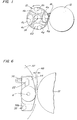
- FIGURE 1 illustrates positional relations among a rotary developing apparatus, developing rollers and a photoreceptor drum.
- FIGURE 2 shows a perspective view of a main modular frame unit providing compartments for each housing a set of modular components.
- FIGURE 3 shows a detailed side view of the rotary developing apparatus as shown in FIGURE 1.
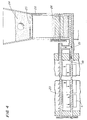
- FIGURE 4 shows a cross-sectional view of a toner transfer mechanism of the rotary developing apparatus.
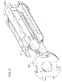
- FIGURE 5 shows a perspective view of one preferred embodiment of a submodular unit according to the current invention.
- FIGURE 6 illustrates an adjustable mechanism for adjusting a gap between a developing roller and a photoreceptor drum.
- FIGURE 7 shows a schematic diagram of gears for activating the developing rollers.
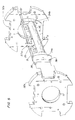
- FIGURE 8 shows an expanded side view of a modular unit frame, a submodular unit and toner transferring mechanisms.
- rotary developing apparatus 10 rotates around axis 14 in a counter- clockwise direction as indicated by an arrow.
- rotary developing apparatus 10 houses four independent developing units 4a-4d, and each developing unit contains a different color toner such as cyan, magenta, yellow and black for color image production.
- Developing rollers 6a-6d are disposed about the circumference of housing 10. As housing 10 rotates, each developing roller is juxtaposed to drum 12. As shown in FIGURE 1, developing roller 6a is rotatably positioned to juxtapose photoreceptor drum 12. This close position to photoreceptor drum 12 defines a developing position.
- the developing roller at the developing position applies toner of a particular color to photoreceptor drum 12 according to a given image.
- Toner on the photoreceptor drum is thereafter transferred to an image forming medium, such as paper (not shown).
- the photoreceptor drum surface is first prepared via an electrophotographic image process to selectively accept toner.
- Each developing unit loads toner onto an associated developing roller.
- Toner loaded onto the developing roller is selectively transferred at the developing position onto the photoreceptor drum over a spacial gap.
- a correct distance for this spacial gap is critical for successful toner transfer.
- Carrier 16 for facilitating this gap transfer is known in the art of electrophotographic image processing. This transfer process repeats for different colors after placing each developing unit at the developing position.
- the transferred toner representing the desired image on the photoreceptor drum is transferred onto the paper.
- FIGURE 2 shows a perspective view of main modular unit frame 3 with pair of side walls 32a, 32b.
- main modular unit frame 3 is placed within the rotary developing apparatus housing (not shown) and divides housing 10 into four compartments for independent developing units.
- Main modular unit frame 3 also provides structural support for housing 10 by connecting each end to side walls 32a and 32b.
- FIGURE 3 shows a more detailed side view of modular developing units 4a-4d.
- Each developing unit has at least a corresponding pair of transport screw shafts 18 and 20 (designated as 18a-18d, 20a-20d in fig. 3), corresponding doctor blade 22 (only blade 22a is designated in fig. 3) and developing roller 6 (designated as rollers 6a-6d in fig. 3).
- a set of the above-described modular components is placed in each of four compartments 3a-3d defined by the structure of main modular unit frame 3 as shown in FIGURE 2.
- toner is loaded onto each developing roller 6a-6d by the corresponding transport screw shaft 18a-18d.
- doctor blades 22a-22d remove excess toner and evenly spread toner on the roller surface.
- the toner Before loading toner onto each developing roller 6a-6d, the toner must first be transported from an external toner cartridge (not shown) to the vicinity of the developing roller by transport screw shafts 18a-18d, as will be described below with respect to FIGURE 4.
- toner transport mechanism includes toner cartridge 24, toner supply unit 28, transport screw shafts 18 and 20, and toner transport duct 21.
- Toner stored in toner supply cartridge 24 is delivered to toner supply unit 28 through opening 25 mainly due to gravity.
- Toner passing into toner supply unit 28 is agitated and further transported to toner transport duct 21 by agitator/transport roller 26.
- Toner on rotating transport screw shaft 18 is pushed forward in transport conduit 21 towards a developing unit.
- developing unit the toner is loaded onto the developing roller (not shown) as previously described. Excess toner is transported back towards toner cartridge 24 by second transport screw shaft 20.
- FIGURE 5 shows an expanded perspective view of a submodular unit.
- submodular unit frame 31 houses doctor blade 22 and developing roller 6 and is adjustably mounted on side plates 32a and 32b by means of adjustable projection 36 and anchoring bore 38.
- three other submodular units are mounted on side plates 32a and 32b.
- Each of submodular units 30a-30d is ultimately placed in the corresponding compartment of the main modular unit frame as shown in FIGURE 3.
- submodular unit frame 31 includes pair of side walls 34a and 34b and backplate 35 extending between side walls 34a and 34b.
- Developing roller 6 is rotatably retained by side walls 34a and 34b while doctor blade 22 is mounted on backplate 35.
- Doctor blade 22 is preferably adjustably mounted to backplate 35 for providing an adjustable gap between the edge of the doctor blade and the developing roller surface. This vertical gap adjustment controls the amount of toner loaded on developing roller 6.
- FIGURE 6 shows that each side wall 34a, 34b of submodular unit frame 30 includes adjustable projection 36 and anchoring bore 38a which provide rotation adjustments around an anchoring axis.
- one end of submodular unit side wall 34 (the side wall 34 in fig. 6 represents one of the side walls 34a or 34b) is anchored to main modular side wall 32 by anchoring bore 38 and anchoring screw 38b.
- the other end of side wall 24 rotates around an axis of anchoring screw 38b in anchoring bore 38b adjusting the spacial gap as indicated by a double headed arrow. This rotation is limited by an elongated slot in adjustable projection 36.
- submodular unit frame 30 is rotated within a compartment of unit frame 3 to adjust the gap between developing roller 6 and the photoreceptor drum, the gap between toner blade 22 and developing roller 6 is kept constant. If doctor blade 22 is not mounted on submodular unit frame 30, the gap between blade 22 and developing roller 6 will change, and consequently the amount of toner loaded on developing roller 6 will be varied.
- the rotation of submodular unit frame 30 adjusts the distance of gap 40 between developing roller 6 at the developing position and photoreceptor drum 12.
- gap distance 40 is specified at 0.57 +/- 0.1 mm for an optimal toner transfer from developing roller 6 to photoreceptor drum 12. While too much gap leads to dropping of toner before reaching photoreceptor drum 12, too little gap also leads to too much toner on photoreceptor drum 12.
- the adjustable range is provided by the slot length in adjustable projection 36 which approximately measures 10 mm.
- the center of developing roller 6 vertically moves approximately +/- 0.2 mm.
- This specification for the gap distance is also suitable for the Ricoh AZALEA copier product line which includes models A166-60, A166-01, A166-02, and A166-03.
- developing roller 6 and photoreceptor drum 12 are rotated in opposite directions. This rotational arrangement also improves the toner transfer between the gap.
- Driving gear 40 is ultimately connected to a motor and drives planetary gear 44 which activates developing roller 10 via intermediate gear 42.
- Planetary gear 44 and developing roller 6 share a common rotational axis, and the radius of these gears is predetermined in such way to accommodate the rotation of the submodular unit for the gap adjustment as described above with respect to FIGURE 6.
- Planetary gear 44 moves around a rotational axis of intermediate gear 42 when the submodular unit is adjustably rotated.
- planetary gear 44 rotates around the circumference of intermediate gear 42 without affecting the activation of developing roller 6.
- FIGURE 8 schematically shows a sequence of assembling the components of the rotary developing apparatus.
- toner transport screw shafts 18 and 20 along with paddles 8 are assembled into the developing unit.
- pre-assembled submodular unit 30 is assembled into main modular unit frame 3.
- pre-assembled submodular unit 30 includes doctor blade 22 and developing roller 6 and a distance of the gap between developing roller 6 and photoreceptor drum 12 is adjusted as submodular unit 30 is mounted. Because of this submodular design, the assembly process as well as the initial gap adjustment is simplified.
- submodular unit 30 Maintenance of the rotary developing apparatus is also facilitated by the above-described submodular unit 30. For example, the subsequent gap adjustment after extended use is individually made for each developing unit. Since submodular unit 30 also accommodates a doctor blade, a constant space between the doctor blade and the developing roller is maintained after the gap adjustment. Additionally, as described above in relation to FIGURE 7, the gap adjustment does not affect the activating gears. Another example of an advantage is that the replacement of the developing roller or a doctor blade is accomplished by swapping the submodular units.
- the above-described submodular concept may be applicable to other components of the modular rotary developing apparatus.
- certain components may be combined into an additional submodular unit in the rotary developing apparatus for the purposes of gaining the above described and other advantages.
Landscapes
- Physics & Mathematics (AREA)
- General Physics & Mathematics (AREA)
- Dry Development In Electrophotography (AREA)
- Color Electrophotography (AREA)
Claims (13)
- Dispositif rotatif modulaire de développement comprenant un tambour photorécepteur (12) destiné au développement d'une image sur un support d'image à l'aide d'un développateur appliqué sélectivement au tambour photorécepteur (12), le dispositif comprenant un châssis principal (3) d'unité modulaire juxtaposé au tambour photorécepteur (12) et plusieurs unités de développement (4a-4d) logées dans le châssis (3), chacune des unités de développement (4a-4d) comprenant :caractérisé en ce qu'une lame de raclage (22) destinée à réguler la quantité de développateur portée par le rouleau de développement (6) est montée sur le châssis (31) d'unité de sous-module si bien que l'espace compris entre le rouleau de développement et la lame de raclage reste constant indépendamment de l'ajustement.un châssis (31) d'unité de sous-module monté sur le châssis principal (3, 32) d'unité modulaire, etun rouleau (6) de développement monté sur le châssis (31) d'unité de sous-module et destiné à appliquer le développateur sur le tambour photorécepteur (12), la position du châssis (31) d'unité de sous-module par rapport au châssis principal (3) d'unité modulaire étant réglable pour l'ajustement d'un espace (40) placé entre le rouleau de développement (6) et le tambour photorécepteur,
- Dispositif selon la revendication 1, dans lequel le châssis (31) d'unité de sous-module comporte en outre :une paire de parois latérales (34a, 34b) destinées à supporter le rouleau de développement (6),une plaque arrière (35) raccordée aux parois latérales pour le support de la lame de raclage (22),un dispositif (38) de fixation placé sur les parois latérales et destiné au montage rotatif d'une première extrémité de la paroi latérale sur le châssis principal (3, 32) d'unité modulaire et délimitant un axe de rotation, etun dispositif réglable (36) placé sur les parois latérales et destiné au montage réglable de l'autre extrémité des parois latérales sur le châssis principal d'unité modulaire, le dispositif réglable limitant la plage de rotation autour de l'axe de rotation et verrouillant les parois latérales à un angle choisi.
- Dispositif selon la revendication 2, dans lequel le dispositif d'ancrage (38) comporte un premier trou taraudé sur le châssis principal d'unité modulaire et un second trou taraudé sur la paroi latérale et une vis fixée au premier trou taraudé et au second trou taraudé.
- Dispositif selon la revendication 3, dans lequel le dispositif réglable (38) comprend un troisième trou taraudé sur le châssis principal d'unité modulaire et un trou allongé formé sur la paroi latérale et une vis fixée au second trou taraudé mais se déplaçant de façon réglable dans le trou allongé.
- Dispositif selon la revendication 4, dans lequel l'axe longitudinal du trou allongé est incliné par rapport à une droite reliant le centre du rouleau de développement (6) au centre du tambour photorécepteur (12).
- Dispositif selon la revendication 1, comprenant en outre plusieurs châssis (31) d'unité de sous-module ayant chacun un rouleau correspondant de développement, les unités de sous-module étant montées chacune de manière réglable sur le châssis principal d'unité modulaire, le châssis principal d'unité modulaire tournant autour d'un axe prédéterminé, l'une des unités de sous-module étant juxtaposée au tambour photorécepteur (12) et délimitant une position de développement, l'unité de sous-module en position de développement étant mobile indépendamment pour l'ajustement d'un espace (40) compris entre le rouleau de développement (6) en position de développement et le tambour photorécepteur (12).
- Dispositif selon la revendication 6, dans lequel l'unité de sous-module en position de développement est tournée de manière réglable autour d'un autre axe prédéterminé pour l'ajustement dudit espace.
- Dispositif selon la revendication 7, comprenant en outre un ensemble de pignons (40, 42, 44, figure 7) destinés à activer le rouleau de développement, le rouleau de développement étant placé indépendamment autour d'un axe de rotation de l'un des pignons, les pignons permettant ainsi l'ajustement de l'espace par maintien de la même distance entre deux pignons quelconques.
- Dispositif selon la revendication 6, dans lequel ledit espace (40) est ajusté afin qu'il élimine pratiquement la chute de développateur par cet espace.
- Dispositif selon la revendication 9, dans lequel le rouleau de développement et le tambour photorécepteur tournent en sens opposés afin que la chute de développateur soit éliminée de façon plus importante.
- Procédé d'assemblage d'un appareil rotatif modulaire de développement selon les revendications 1 à 10, dans lequel un développateur est transporté vers un rouleau de développement par le mécanisme de transport, comprenant les étapes suivantes :a) la disposition du mécanisme de transport dans l'unité modulaire principale,b) la disposition du rouleau de développement et de la lame de raclage dans l'unité de sous-module,c) la disposition de l'unité de sous-module assemblée dans l'étape b) dans l'unité principale modulaire assemblée dans l'étape a), etd) la disposition de l'unité principale modulaire assemblée dans l'étape c) en position adjacente au tambour photorécepteur.
- Procédé d'ajustement d'une unité de sous-module d'un appareil rotatif de développement selon les revendications 1 à 10, comprenant les étapes suivantes :a) l'exposition de l'unité de sous-module dans l'unité principale modulaire afin qu'un opérateur puisse avoir accès à l'unité de sous-module,b) le desserrage d'une vis réglable sur l'unité de sous-module, l'unité de sous-module étant montée de façon réglable sur l'unité principale modulaire par cette vis,c) l'ajustement de l'espace compris entre le rouleau de développement et le tambour photorécepteur, etd) le serrage de la vis réglable pour la stabilisation de l'unité de sous-module.
- Procédé selon la revendication 12, dans lequel l'étape c) est exécutée par rotation d'une première extrémité de l'unité de sous-module autour d'un axe prédéterminé à l'autre extrémité de l'unité de sous-module afin que ledit espace soit ajustée à l'autre extrémité rotative.
Applications Claiming Priority (4)
| Application Number | Priority Date | Filing Date | Title |
|---|---|---|---|
| JP266660/93 | 1993-10-25 | ||
| JP5266660A JPH07121027A (ja) | 1993-10-25 | 1993-10-25 | 現像装置 |
| JP5296658A JPH07152239A (ja) | 1993-11-26 | 1993-11-26 | トナー補給装置及び現像装置 |
| JP296658/93 | 1993-11-26 |
Publications (3)
| Publication Number | Publication Date |
|---|---|
| EP0650102A2 EP0650102A2 (fr) | 1995-04-26 |
| EP0650102A3 EP0650102A3 (fr) | 1995-05-24 |
| EP0650102B1 true EP0650102B1 (fr) | 1999-03-31 |
Family
ID=26547538
Family Applications (2)
| Application Number | Title | Priority Date | Filing Date |
|---|---|---|---|
| EP94116812A Expired - Lifetime EP0650102B1 (fr) | 1993-10-25 | 1994-10-25 | Sous-assemblage pour utilisation dans un appareil de développement rotatif modulaire |
| EP94116806A Expired - Lifetime EP0654713B1 (fr) | 1993-10-25 | 1994-10-25 | Cartouche de fourniture de toner pour un dispositif de développement rotatif |
Family Applications After (1)
| Application Number | Title | Priority Date | Filing Date |
|---|---|---|---|
| EP94116806A Expired - Lifetime EP0654713B1 (fr) | 1993-10-25 | 1994-10-25 | Cartouche de fourniture de toner pour un dispositif de développement rotatif |
Country Status (4)
| Country | Link |
|---|---|
| US (2) | US5768662A (fr) |
| EP (2) | EP0650102B1 (fr) |
| DE (2) | DE69420677T2 (fr) |
| ES (2) | ES2129561T3 (fr) |
Families Citing this family (21)
| Publication number | Priority date | Publication date | Assignee | Title |
|---|---|---|---|---|
| JPH07333978A (ja) * | 1994-06-05 | 1995-12-22 | Ricoh Co Ltd | 回転型現像装置 |
| US5828934A (en) * | 1995-06-07 | 1998-10-27 | Konica Corporation | Driving device of developing units and toner replenishing units for use in image forming apparatus |
| JPH09114179A (ja) * | 1995-10-16 | 1997-05-02 | Ricoh Co Ltd | カラー画像形成装置 |
| JPH09230694A (ja) * | 1996-02-27 | 1997-09-05 | Canon Inc | 電子写真画像形成装置 |
| EP0807866A1 (fr) * | 1996-05-17 | 1997-11-19 | Agfa-Gevaert N.V. | Dispositif de développement électrostatographique comprenant un réservoir de dosage de toner |
| KR100310126B1 (ko) * | 1997-06-06 | 2002-02-19 | 이토가 미찌야 | 감광체드럼이통합된회전형현상유니트 |
| JP3421545B2 (ja) * | 1997-08-04 | 2003-06-30 | 株式会社日立製作所 | 現像装置及びそれを備えた画像形成装置 |
| JP3677408B2 (ja) * | 1998-04-20 | 2005-08-03 | 株式会社リコー | 画像形成装置 |
| US6226481B1 (en) | 1998-12-07 | 2001-05-01 | Ricoh Company, Ltd. | Image forming apparatus with control over developing unit during an idle running of an intermediate image transfer body |
| US6301460B1 (en) * | 2000-09-21 | 2001-10-09 | Hewlett-Packard Company | All-in-one toner cartridge |
| US6510305B1 (en) * | 2000-11-28 | 2003-01-21 | Xerox Corporation | Toner transport apparatus using flexible augers |
| JP4329297B2 (ja) * | 2002-03-01 | 2009-09-09 | コニカミノルタビジネステクノロジーズ株式会社 | カラー画像形成装置 |
| US6963713B2 (en) * | 2002-04-24 | 2005-11-08 | Canon Kabushiki Kaisha | Developer supply container with a plurality of feeding projections |
| US6987942B2 (en) * | 2002-04-24 | 2006-01-17 | Canon Kabushiki Kaisha | Toner supply kit |
| WO2004081673A1 (fr) * | 2003-03-10 | 2004-09-23 | Sharp Kabushiki Kaisha | Cuve de reception de revelateur et dispositif de formation d'images |
| JP4681833B2 (ja) * | 2003-09-19 | 2011-05-11 | 株式会社リコー | 画像形成装置 |
| JP4037390B2 (ja) * | 2004-07-07 | 2008-01-23 | シャープ株式会社 | 現像剤供給装置及びそれを備えた画像形成装置 |
| US7457570B2 (en) * | 2004-08-06 | 2008-11-25 | Ricoh Company, Ltd. | Image forming apparatus including a magnetic brush developing system using a two-component developer comprising toner and carrier |
| US7177574B2 (en) * | 2004-11-29 | 2007-02-13 | Kabushiki Kaisha Toshiba | Image forming apparatus and developing gap adjusting method in image forming apparatus |
| US7386249B2 (en) * | 2005-06-07 | 2008-06-10 | Lexmark International, Inc. | Roller with mechanical properties influenced by rotation |
| JP5007755B2 (ja) | 2010-06-07 | 2012-08-22 | ブラザー工業株式会社 | 画像形成装置 |
Citations (1)
| Publication number | Priority date | Publication date | Assignee | Title |
|---|---|---|---|---|
| US4782360A (en) * | 1986-01-13 | 1988-11-01 | Sharp Kabushiki Kaisha | Rotary type developing apparatus |
Family Cites Families (28)
| Publication number | Priority date | Publication date | Assignee | Title |
|---|---|---|---|---|
| US3953121A (en) * | 1974-10-29 | 1976-04-27 | Xerox Corporation | Articulated development apparatus |
| JPS58126554A (ja) * | 1982-01-25 | 1983-07-28 | Canon Inc | 現像装置 |
| JPS59223468A (ja) * | 1983-06-03 | 1984-12-15 | Fuji Xerox Co Ltd | 複写機の現像器支持機構 |
| JPS60150073A (ja) * | 1984-01-18 | 1985-08-07 | Toshiba Corp | 像形成装置 |
| US4743938A (en) * | 1984-10-16 | 1988-05-10 | Canon Kabushiki Kaisha | Color image forming apparatus |
| JPS61103175A (ja) * | 1984-10-26 | 1986-05-21 | Canon Inc | 回転現像装置 |
| JPS61259282A (ja) * | 1985-05-14 | 1986-11-17 | Canon Inc | 現像装置 |
| JPH0736088B2 (ja) * | 1985-11-07 | 1995-04-19 | 株式会社リコー | 多色現像装置 |
| JPS62163073A (ja) * | 1986-01-13 | 1987-07-18 | Sharp Corp | 回転式現像装置 |
| JPS62163071A (ja) * | 1986-01-13 | 1987-07-18 | Sharp Corp | 回転式現像装置の現像ユニツト交換装置 |
| JPS62163072A (ja) * | 1986-01-13 | 1987-07-18 | Sharp Corp | 回転式現像装置 |
| GB2194179B (en) * | 1986-04-24 | 1990-03-14 | Ricoh Kk | Rotary multicolor developing apparatus |
| US4772916A (en) * | 1986-07-16 | 1988-09-20 | Canon Kabushiki Kaisha | Multi-color image forming apparatus |
| JPH0743551B2 (ja) * | 1986-09-20 | 1995-05-15 | 株式会社リコー | 回転型現像装置 |
| JPH0746242B2 (ja) * | 1986-09-20 | 1995-05-17 | 株式会社リコー | 回転型現像装置 |
| US4792825A (en) * | 1986-09-20 | 1988-12-20 | Ricoh Company, Ltd. | Rotary developing device for image-forming apparatus |
| JPH0746243B2 (ja) * | 1986-09-20 | 1995-05-17 | 株式会社リコー | 画像形成装置の回転型現像装置 |
| JP2729372B2 (ja) * | 1986-09-20 | 1998-03-18 | 株式会社リコー | 画像形成装置の回転型現像装置 |
| JPH07117783B2 (ja) * | 1986-09-20 | 1995-12-18 | 株式会社リコー | 画像形成装置の回転型現像装置 |
| US4894684A (en) * | 1987-03-10 | 1990-01-16 | Canon Kabushiki Kaisha | Image forming apparatus with developing device accommodating apparatus |
| US5030997A (en) * | 1988-07-28 | 1991-07-09 | Universal Developer And Manufacturing Co. | Toner dispenser for xerographic machines |
| JPH0266582A (ja) * | 1988-08-31 | 1990-03-06 | Mita Ind Co Ltd | 画像形成装置の多色現像装置 |
| JPH02205863A (ja) * | 1989-02-03 | 1990-08-15 | Minolta Camera Co Ltd | 現像装置 |
| US5109254A (en) * | 1989-08-25 | 1992-04-28 | Ricoh Company, Ltd. | Developing apparatus |
| JPH0450975A (ja) * | 1990-06-15 | 1992-02-19 | Canon Inc | 画像形成装置 |
| JP2983310B2 (ja) * | 1991-01-29 | 1999-11-29 | 株式会社リコー | 画像形成装置の回転型現像装置 |
| JP3222913B2 (ja) * | 1992-02-27 | 2001-10-29 | 株式会社リコー | 回転型現像装置を用いた画像形成装置 |
| JP3187522B2 (ja) * | 1992-04-30 | 2001-07-11 | 株式会社リコー | 回転型現像装置を用いた画像形成装置 |
-
1994
- 1994-10-25 ES ES94116812T patent/ES2129561T3/es not_active Expired - Lifetime
- 1994-10-25 DE DE69420677T patent/DE69420677T2/de not_active Expired - Fee Related
- 1994-10-25 EP EP94116812A patent/EP0650102B1/fr not_active Expired - Lifetime
- 1994-10-25 US US08/328,477 patent/US5768662A/en not_active Expired - Fee Related
- 1994-10-25 US US08/328,478 patent/US5612769A/en not_active Expired - Lifetime
- 1994-10-25 DE DE69417507T patent/DE69417507T2/de not_active Expired - Fee Related
- 1994-10-25 EP EP94116806A patent/EP0654713B1/fr not_active Expired - Lifetime
- 1994-10-25 ES ES94116806T patent/ES2137298T3/es not_active Expired - Lifetime
Patent Citations (1)
| Publication number | Priority date | Publication date | Assignee | Title |
|---|---|---|---|---|
| US4782360A (en) * | 1986-01-13 | 1988-11-01 | Sharp Kabushiki Kaisha | Rotary type developing apparatus |
Also Published As
| Publication number | Publication date |
|---|---|
| EP0650102A2 (fr) | 1995-04-26 |
| EP0654713B1 (fr) | 1999-09-15 |
| DE69420677T2 (de) | 2000-03-02 |
| ES2137298T3 (es) | 1999-12-16 |
| EP0650102A3 (fr) | 1995-05-24 |
| US5768662A (en) | 1998-06-16 |
| DE69417507D1 (de) | 1999-05-06 |
| ES2129561T3 (es) | 1999-06-16 |
| DE69417507T2 (de) | 1999-08-12 |
| EP0654713A1 (fr) | 1995-05-24 |
| DE69420677D1 (de) | 1999-10-21 |
| US5612769A (en) | 1997-03-18 |
Similar Documents
| Publication | Publication Date | Title |
|---|---|---|
| EP0650102B1 (fr) | Sous-assemblage pour utilisation dans un appareil de développement rotatif modulaire | |
| US7158735B2 (en) | Process cartridge, mounting method of electrophotographic photosensitive drum and replacing method of the photosensitive drum | |
| JPH11109742A (ja) | プロセスカートリッジ及び電子写真画像形成装置 | |
| US5138372A (en) | Image forming apparatus and an image member cartridge | |
| JPH046030Y2 (fr) | ||
| US7233756B2 (en) | Image forming apparatus including gravity-operated opening and closing member for discharging excess developer | |
| JP3225360B2 (ja) | 画像形成装置 | |
| JPH10105019A (ja) | プロセスカートリッジ及び電子写真画像形成装置 | |
| JP3057124B2 (ja) | 現像装置の位置決め機構 | |
| JP3135671B2 (ja) | 電子写真装置 | |
| KR100337844B1 (ko) | 전자사진프로세서의토너교반장치 | |
| JP3217526B2 (ja) | 現像装置及び画像形成装置 | |
| JP3146213B2 (ja) | カラー画像記録装置 | |
| KR200158207Y1 (ko) | 현상기의 토너 보급 규제장치 | |
| KR200246737Y1 (ko) | 화상형성장치의토너량공급조절장치 | |
| JP2000347472A (ja) | 画像形成装置 | |
| JPH07181797A (ja) | 画像形成装置 | |
| JP3458868B2 (ja) | 回転型現像装置 | |
| JP2003167412A (ja) | 画像形成装置 | |
| JPH0377973A (ja) | カラー画像形成装置 | |
| JP2024005392A (ja) | 現像装置および画像形成装置 | |
| JP2813203B2 (ja) | 回転現像装置 | |
| KR100362565B1 (ko) | 현상기의토너공급조절장치 | |
| JP2003167433A (ja) | 現像カートリッジ及び画像形成装置 | |
| JP2767786B2 (ja) | 現像装置 |
Legal Events
| Date | Code | Title | Description |
|---|---|---|---|
| PUAI | Public reference made under article 153(3) epc to a published international application that has entered the european phase |
Free format text: ORIGINAL CODE: 0009012 |
|
| PUAL | Search report despatched |
Free format text: ORIGINAL CODE: 0009013 |
|
| 17P | Request for examination filed |
Effective date: 19941025 |
|
| AK | Designated contracting states |
Kind code of ref document: A2 Designated state(s): DE ES FR GB IT |
|
| AK | Designated contracting states |
Kind code of ref document: A3 Designated state(s): DE ES FR GB IT |
|
| 17Q | First examination report despatched |
Effective date: 19961119 |
|
| GRAG | Despatch of communication of intention to grant |
Free format text: ORIGINAL CODE: EPIDOS AGRA |
|
| GRAG | Despatch of communication of intention to grant |
Free format text: ORIGINAL CODE: EPIDOS AGRA |
|
| GRAH | Despatch of communication of intention to grant a patent |
Free format text: ORIGINAL CODE: EPIDOS IGRA |
|
| GRAH | Despatch of communication of intention to grant a patent |
Free format text: ORIGINAL CODE: EPIDOS IGRA |
|
| GRAA | (expected) grant |
Free format text: ORIGINAL CODE: 0009210 |
|
| ITF | It: translation for a ep patent filed | ||
| AK | Designated contracting states |
Kind code of ref document: B1 Designated state(s): DE ES FR GB IT |
|
| REF | Corresponds to: |
Ref document number: 69417507 Country of ref document: DE Date of ref document: 19990506 |
|
| REG | Reference to a national code |
Ref country code: ES Ref legal event code: FG2A Ref document number: 2129561 Country of ref document: ES Kind code of ref document: T3 |
|
| ET | Fr: translation filed | ||
| PLBE | No opposition filed within time limit |
Free format text: ORIGINAL CODE: 0009261 |
|
| STAA | Information on the status of an ep patent application or granted ep patent |
Free format text: STATUS: NO OPPOSITION FILED WITHIN TIME LIMIT |
|
| 26N | No opposition filed | ||
| REG | Reference to a national code |
Ref country code: GB Ref legal event code: IF02 |
|
| PGFP | Annual fee paid to national office [announced via postgrant information from national office to epo] |
Ref country code: DE Payment date: 20081027 Year of fee payment: 15 |
|
| PGFP | Annual fee paid to national office [announced via postgrant information from national office to epo] |
Ref country code: ES Payment date: 20081030 Year of fee payment: 15 |
|
| PGFP | Annual fee paid to national office [announced via postgrant information from national office to epo] |
Ref country code: IT Payment date: 20081028 Year of fee payment: 15 |
|
| PGFP | Annual fee paid to national office [announced via postgrant information from national office to epo] |
Ref country code: FR Payment date: 20081014 Year of fee payment: 15 |
|
| PGFP | Annual fee paid to national office [announced via postgrant information from national office to epo] |
Ref country code: GB Payment date: 20081022 Year of fee payment: 15 |
|
| REG | Reference to a national code |
Ref country code: FR Ref legal event code: ST Effective date: 20100630 |
|
| PG25 | Lapsed in a contracting state [announced via postgrant information from national office to epo] |
Ref country code: FR Free format text: LAPSE BECAUSE OF NON-PAYMENT OF DUE FEES Effective date: 20091102 Ref country code: DE Free format text: LAPSE BECAUSE OF NON-PAYMENT OF DUE FEES Effective date: 20100501 |
|
| PG25 | Lapsed in a contracting state [announced via postgrant information from national office to epo] |
Ref country code: GB Free format text: LAPSE BECAUSE OF NON-PAYMENT OF DUE FEES Effective date: 20091025 |
|
| REG | Reference to a national code |
Ref country code: ES Ref legal event code: FD2A Effective date: 20110310 |
|
| PG25 | Lapsed in a contracting state [announced via postgrant information from national office to epo] |
Ref country code: IT Free format text: LAPSE BECAUSE OF NON-PAYMENT OF DUE FEES Effective date: 20091025 |
|
| PG25 | Lapsed in a contracting state [announced via postgrant information from national office to epo] |
Ref country code: ES Free format text: LAPSE BECAUSE OF NON-PAYMENT OF DUE FEES Effective date: 20110309 |
|
| PG25 | Lapsed in a contracting state [announced via postgrant information from national office to epo] |
Ref country code: ES Free format text: LAPSE BECAUSE OF NON-PAYMENT OF DUE FEES Effective date: 20091026 |