EP0626715A2 - Lampe luminescente pour insertion - Google Patents
Lampe luminescente pour insertion Download PDFInfo
- Publication number
- EP0626715A2 EP0626715A2 EP94107826A EP94107826A EP0626715A2 EP 0626715 A2 EP0626715 A2 EP 0626715A2 EP 94107826 A EP94107826 A EP 94107826A EP 94107826 A EP94107826 A EP 94107826A EP 0626715 A2 EP0626715 A2 EP 0626715A2
- Authority
- EP
- European Patent Office
- Prior art keywords
- light source
- hollow body
- source according
- series resistor
- base
- Prior art date
- Legal status (The legal status is an assumption and is not a legal conclusion. Google has not performed a legal analysis and makes no representation as to the accuracy of the status listed.)
- Granted
Links
Images
Classifications
-
- H—ELECTRICITY
- H01—ELECTRIC ELEMENTS
- H01J—ELECTRIC DISCHARGE TUBES OR DISCHARGE LAMPS
- H01J5/00—Details relating to vessels or to leading-in conductors common to two or more basic types of discharge tubes or lamps
- H01J5/50—Means forming part of the tube or lamps for the purpose of providing electrical connection to it
-
- H—ELECTRICITY
- H01—ELECTRIC ELEMENTS
- H01J—ELECTRIC DISCHARGE TUBES OR DISCHARGE LAMPS
- H01J61/00—Gas-discharge or vapour-discharge lamps
- H01J61/02—Details
- H01J61/56—One or more circuit elements structurally associated with the lamp
-
- H—ELECTRICITY
- H01—ELECTRIC ELEMENTS
- H01J—ELECTRIC DISCHARGE TUBES OR DISCHARGE LAMPS
- H01J61/00—Gas-discharge or vapour-discharge lamps
- H01J61/64—Cathode glow lamps
-
- H—ELECTRICITY
- H01—ELECTRIC ELEMENTS
- H01R—ELECTRICALLY-CONDUCTIVE CONNECTIONS; STRUCTURAL ASSOCIATIONS OF A PLURALITY OF MUTUALLY-INSULATED ELECTRICAL CONNECTING ELEMENTS; COUPLING DEVICES; CURRENT COLLECTORS
- H01R33/00—Coupling devices specially adapted for supporting apparatus and having one part acting as a holder providing support and electrical connection via a counterpart which is structurally associated with the apparatus, e.g. lamp holders; Separate parts thereof
- H01R33/05—Two-pole devices
- H01R33/06—Two-pole devices with two current-carrying pins, blades or analogous contacts, having their axes parallel to each other
- H01R33/09—Two-pole devices with two current-carrying pins, blades or analogous contacts, having their axes parallel to each other for baseless lamp bulb
Definitions
- the invention relates to a light source, in particular a glow lamp for plugging into a socket, in particular for use in electrical installation devices, such as electrical switches, buttons, dimmers and the like, with a hollow body, preferably made of glass, with electrodes arranged therein, the connecting wires of which Underside of the hollow glass body are isolated from each other and serve as connection contacts for mating contacts located in the socket and with a series resistor, which is interposed between the glow lamp and an electrical supply network.
- a light source in particular a glow lamp for plugging into a socket, in particular for use in electrical installation devices, such as electrical switches, buttons, dimmers and the like
- a hollow body preferably made of glass, with electrodes arranged therein, the connecting wires of which Underside of the hollow glass body are isolated from each other and serve as connection contacts for mating contacts located in the socket and with a series resistor, which is interposed between the glow lamp and an electrical supply network.
- the light sources are usually used in a socketed form.
- the light sources provided with a hollow body which surrounds the light source can have a base molded thereon which is inserted into the respective device, or an additional plug-in base is required in which the light sources are used.
- the connecting wires led out of the hollow body are bent at their ends and serve as connecting contacts which ensure the current connection when inserted into the socket with the mating contacts located there.
- the cabbage body formed from glass is provided on its underside with a protective cap which receives its underside and the series resistor connected to it. Furthermore, the other connecting wire led out of the hollow glass body and the free end of the series resistor, both of which serve as connecting contacts, are also isolated from one another through the protective cap, where they are bent back in the same way, thereby forming the desired contact surface on the one hand and on the other hand, prevent the protective cap from sliding off the hollow body.
- the series resistor is cylindrical, with connecting wires each connecting to the end faces.
- Such a series resistor is known as a commercially available carbon film or metal film resistor.
- the protective cap is made of insulating material, advantageously of injection-molded thermoplastic and is adapted with its end facing away from the hollow body to the geometry of the plug-in base and is designed to be insertable therein.
- each light source is used only with the required series resistor, so that malfunctions or interruptions in operation are practically excluded. Furthermore, due to the configuration according to the invention, a space-saving design is achieved, so that the inventive Light source can also be used in devices with limited space.
- the invention offers the advantage that a cost-effective replacement in the event of defects in lamps or in the event of a change in the illuminance of the respective lamp is possible, since only the lamp body but not the base is to be replaced.
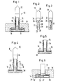
- FIG. 1 shows an electrical light source 10, which here is designed in particular as a glow lamp, which consists of the actual light or lamp part 12 and an associated base 14.
- the base 14 is inserted into an electrical device 16 shown only schematically in longitudinal section here.
- the electrical connection of the base 14 to the electrical device 16 is established with the aid of contact tabs 18 which protrude from the base and which cooperate with electrical conductors which are not shown here in the electrical device 16. Further details of the base 14 are shown in FIGS. 4 to 6.
- the light source 12 shown in FIG. 1 is shown in side view in FIG. It consists of a hollow body 20 made of glass, on the underside 22 of which a protective cap 24 made of injection-molded thermoplastic is attached. Furthermore, on the underside 22 of the light source 20, lead wires 25, 26 are led out insulated from one another. While the first connecting wire 25 is passed through the protective cap 24 and is likewise led outward again at the lower end of the protective cap 24 and forms a connecting contact 27 there, the second connecting wire 26 with an electrical resistor 30 is led out from the underside 22 of the light source 20 connected, the free end 29 led out of the protective cap 24 to form a terminal contact 28 on the diametrically opposite side of the terminal contact 27.
- the light source 10 which is inserted into an electrical device 16 according to FIG. 1, is shown in longitudinal section in a single representation, with the use of lights or lamps and the attached protective cap 24 only the contours are shown.
- the plug-in base 14 consists of a tube-like upper part 34 which connects centrally to a lower part 36 which is approximately square in cross section.
- the upper part 34 is provided at a certain height, which is adapted to the installation conditions of the relevant electrical device 16, in which the light source is to be installed, with latching lugs 35, which ensure that the recess provided in the electrical device 16 is provided for this purpose imported base 14 can not return.
- the contacts on the base 14, i. H. the contact tabs 18 protruding from the lower part 36 of the base 14 are arranged in a resilient manner, as can be seen in particular from FIG. 6.
- the contact lugs 18 are connected via flat conductors to counter contacts 19 in the interior of the upper part 34 of the base 14. These counter contacts 19 are used to make contact with the connection contacts 27, 28 of the lighting or lamp unit 12 designed as a plug insert.
- each mating contact 19 has a preferred contact point, so as to connect with the contacts 27, 28 of the light or lamp unit 12.
- the cause of the resilient yielding is shown in FIG. 6 shown below.
- the preferably spring-hard contact material, for. B. spring bronze, formed contact lugs 18 are in the rest position shown in Figures 4 and 5 on the upper inner surface of the lower part 36, where it acts on a molded on the lower inner surface of the lower part 36 cam 37. If the plug insert 14, as shown in FIG. 1 and FIG. 6, is inserted into an electrical device 16, the contact lugs 18 come into operative connection with the connection contacts of the electrical device 16 provided for this purpose, which are not shown here, and are repositioned on the end face due to the geometric conditions applied below so that they bend downward, as shown in Figure 6. With the help of this spring action, a high degree of contact reliability is achieved, so that only a low contact resistance results.
- the socket 14 is also made as an injection molded part made of thermoplastic and consists of the above-mentioned upper part 34 and the lower part 36.
- the lower part 36 is also made in two parts and consists of a cover part 38 to which the upper part 34 connects, a trough-like receiving part 39, which the cover part 38 together with the electrical conductors 18, 19 arranged therein.
- the cover part 38 is captively connected to the receiving part 39 by means of a film hinge, not shown here. In this way the risk of one of the two parts being lost is reduced.
Applications Claiming Priority (2)
| Application Number | Priority Date | Filing Date | Title |
|---|---|---|---|
| DE4317491A DE4317491A1 (de) | 1993-05-26 | 1993-05-26 | Glimmlampe zum Einstecken |
| DE4317491 | 1993-05-26 |
Publications (3)
| Publication Number | Publication Date |
|---|---|
| EP0626715A2 true EP0626715A2 (fr) | 1994-11-30 |
| EP0626715A3 EP0626715A3 (fr) | 1995-11-29 |
| EP0626715B1 EP0626715B1 (fr) | 1999-01-07 |
Family
ID=6488942
Family Applications (1)
| Application Number | Title | Priority Date | Filing Date |
|---|---|---|---|
| EP94107826A Expired - Lifetime EP0626715B1 (fr) | 1993-05-26 | 1994-05-20 | Source lumineuse |
Country Status (4)
| Country | Link |
|---|---|
| EP (1) | EP0626715B1 (fr) |
| AT (1) | ATE175518T1 (fr) |
| DE (2) | DE4317491A1 (fr) |
| ES (1) | ES2129087T3 (fr) |
Cited By (2)
| Publication number | Priority date | Publication date | Assignee | Title |
|---|---|---|---|---|
| WO1997015940A2 (fr) * | 1995-10-26 | 1997-05-01 | Philips Electronics N.V. | Ampoule electrique a culot |
| EP1126495A2 (fr) * | 2000-02-04 | 2001-08-22 | ABBPATENT GmbH | Illumination d'un dispositif d'installation électrique/électronique |
Families Citing this family (2)
| Publication number | Priority date | Publication date | Assignee | Title |
|---|---|---|---|---|
| DE19628755A1 (de) * | 1996-07-17 | 1998-01-22 | Abb Patent Gmbh | Beleuchtungseinsatz |
| DE19739022A1 (de) * | 1997-09-06 | 1999-03-11 | Hella Kg Hueck & Co | Reflektorleuchte |
Citations (13)
| Publication number | Priority date | Publication date | Assignee | Title |
|---|---|---|---|---|
| US2285875A (en) * | 1940-05-24 | 1942-06-09 | Ohio Carbon Company | Electric lamp assembly |
| US2558747A (en) * | 1945-10-22 | 1951-07-03 | William B Greenlee | Electric lighting system |
| US2561151A (en) * | 1948-09-02 | 1951-07-17 | Ohio Carbon Company | Electrode and resistor assembly unit |
| FR1046935A (fr) * | 1951-11-27 | 1953-12-09 | Cie Ind De Tubes Et Lampes Ele | Lampe de multiple téléphonique |
| DE919960C (de) * | 1951-05-12 | 1954-11-08 | Siemens Ag | Glimmlampe |
| US2740111A (en) * | 1952-08-21 | 1956-03-27 | Etc Inc | Combined signal lamp and resistor |
| FR1204037A (fr) * | 1958-04-12 | 1960-01-22 | Perfectionnements aux petites lampes au néon et autres gaz rares dans le but d'en augmenter l'éclat | |
| DE1106417B (de) * | 1959-06-13 | 1961-05-10 | Hanning Robert | Elektrische Kleinlampe, insbesondere Glimmlampe |
| FR2016561A1 (fr) * | 1968-08-29 | 1970-05-08 | Philips Nv | |
| DE7223900U (fr) * | 1973-11-08 | Patent-Treuhand-Ges Fuer Elektr Gluehlampen Mbh | ||
| US4101187A (en) * | 1977-06-30 | 1978-07-18 | Collier Ben C | Socket for wedge base bulbs |
| EP0075304A1 (fr) * | 1981-09-21 | 1983-03-30 | Patent-Treuhand-Gesellschaft für elektrische Glühlampen mbH | Lumière indicatrice |
| EP0520694A2 (fr) * | 1991-06-28 | 1992-12-30 | MARRIOT INTERNATIONAL Co. Ltd. | Ensemble de support pour ampoule électrique |
Family Cites Families (13)
| Publication number | Priority date | Publication date | Assignee | Title |
|---|---|---|---|---|
| DE673993C (de) * | 1937-11-23 | 1939-04-01 | Patra Patent Treuhand | Elektrische Kathodenglimmlichtlampe von Zwerglampengroesse |
| NL169406B (nl) * | 1951-05-13 | Yoshida Kogyo Kk | Verstelbare bevestigingsinrichting. | |
| DE1465255A1 (de) * | 1964-02-20 | 1969-02-06 | Busch Jaeger Duerener Metall | Isolierstoff-Fassung fuer eine- oder Gluehlampe fuer elektrische Installationsgeraete |
| DE1589301A1 (de) * | 1967-09-08 | 1970-03-05 | Patra Patent Treuhand | Zwergglimmlampe |
| DE1981364U (de) * | 1968-01-09 | 1968-03-21 | Hochkoepper & Co P | Installationsapparat mit kontrollampe. |
| DE7124134U (de) * | 1971-06-23 | 1971-10-14 | Baer Elektrowerke Kg | Sperrvorrichtung fuer elektrische steckdosen |
| DE8411762U1 (de) * | 1984-04-14 | 1984-07-26 | Hurst & Schröder GmbH, 5980 Werdohl | Elektrische Signalleuchte |
| DE3536006A1 (de) * | 1985-10-09 | 1987-04-09 | Bbc Brown Boveri & Cie | Glimmlampeneinsatz fuer elektrische installationsgeraete |
| DE3629025A1 (de) * | 1986-08-27 | 1988-03-10 | Oktalite Ges Fuer Beleuchtungs | Beleuchtungsvorrichtung unter verwendung einer punktartigen lichtquelle |
| DE3704467C2 (de) * | 1987-02-13 | 1997-02-20 | Georg J Klug | Lichtquelle mit den Außenabmessungen einer Kleinglühlampe |
| GB8729594D0 (en) * | 1987-12-18 | 1988-02-03 | A F Bulgin & Co Plc | Electrical connector |
| DE8913269U1 (fr) * | 1989-11-09 | 1990-03-08 | Telebox Gerhard Mueller, 8911 Puergen, De | |
| SU1762324A1 (ru) * | 1990-04-09 | 1992-09-15 | В.И.Калабурдин | Выключатель с подсвечивающим устройством |
-
1993
- 1993-05-26 DE DE4317491A patent/DE4317491A1/de not_active Withdrawn
-
1994
- 1994-05-20 AT AT94107826T patent/ATE175518T1/de active
- 1994-05-20 EP EP94107826A patent/EP0626715B1/fr not_active Expired - Lifetime
- 1994-05-20 DE DE59407577T patent/DE59407577D1/de not_active Expired - Lifetime
- 1994-05-20 ES ES94107826T patent/ES2129087T3/es not_active Expired - Lifetime
Patent Citations (13)
| Publication number | Priority date | Publication date | Assignee | Title |
|---|---|---|---|---|
| DE7223900U (fr) * | 1973-11-08 | Patent-Treuhand-Ges Fuer Elektr Gluehlampen Mbh | ||
| US2285875A (en) * | 1940-05-24 | 1942-06-09 | Ohio Carbon Company | Electric lamp assembly |
| US2558747A (en) * | 1945-10-22 | 1951-07-03 | William B Greenlee | Electric lighting system |
| US2561151A (en) * | 1948-09-02 | 1951-07-17 | Ohio Carbon Company | Electrode and resistor assembly unit |
| DE919960C (de) * | 1951-05-12 | 1954-11-08 | Siemens Ag | Glimmlampe |
| FR1046935A (fr) * | 1951-11-27 | 1953-12-09 | Cie Ind De Tubes Et Lampes Ele | Lampe de multiple téléphonique |
| US2740111A (en) * | 1952-08-21 | 1956-03-27 | Etc Inc | Combined signal lamp and resistor |
| FR1204037A (fr) * | 1958-04-12 | 1960-01-22 | Perfectionnements aux petites lampes au néon et autres gaz rares dans le but d'en augmenter l'éclat | |
| DE1106417B (de) * | 1959-06-13 | 1961-05-10 | Hanning Robert | Elektrische Kleinlampe, insbesondere Glimmlampe |
| FR2016561A1 (fr) * | 1968-08-29 | 1970-05-08 | Philips Nv | |
| US4101187A (en) * | 1977-06-30 | 1978-07-18 | Collier Ben C | Socket for wedge base bulbs |
| EP0075304A1 (fr) * | 1981-09-21 | 1983-03-30 | Patent-Treuhand-Gesellschaft für elektrische Glühlampen mbH | Lumière indicatrice |
| EP0520694A2 (fr) * | 1991-06-28 | 1992-12-30 | MARRIOT INTERNATIONAL Co. Ltd. | Ensemble de support pour ampoule électrique |
Cited By (4)
| Publication number | Priority date | Publication date | Assignee | Title |
|---|---|---|---|---|
| WO1997015940A2 (fr) * | 1995-10-26 | 1997-05-01 | Philips Electronics N.V. | Ampoule electrique a culot |
| WO1997015940A3 (fr) * | 1995-10-26 | 1997-06-26 | Philips Electronics Nv | Ampoule electrique a culot |
| EP1126495A2 (fr) * | 2000-02-04 | 2001-08-22 | ABBPATENT GmbH | Illumination d'un dispositif d'installation électrique/électronique |
| EP1126495A3 (fr) * | 2000-02-04 | 2003-01-08 | ABB PATENT GmbH | Illumination d'un dispositif d'installation électrique/électronique |
Also Published As
| Publication number | Publication date |
|---|---|
| DE4317491A1 (de) | 1994-12-01 |
| ES2129087T3 (es) | 1999-06-01 |
| EP0626715B1 (fr) | 1999-01-07 |
| DE59407577D1 (de) | 1999-02-18 |
| ATE175518T1 (de) | 1999-01-15 |
| EP0626715A3 (fr) | 1995-11-29 |
Similar Documents
| Publication | Publication Date | Title |
|---|---|---|
| DE2340181C2 (de) | Leuchtenstecker für Leuchtbildsteckplatten | |
| EP1096606A1 (fr) | Borne de connexion | |
| DE3227091C2 (fr) | ||
| DE102017114730B4 (de) | Leuchtmittel und Federkontakt zur elektrischen Verbindung zweier Platinen | |
| DE2441318C2 (de) | Sicherheitsvorrichtung für elektrische Verbindungsvorrichtungen | |
| WO1981001082A1 (fr) | Dispositif de couplage electrique | |
| EP0626715B1 (fr) | Source lumineuse | |
| DE8431386U1 (de) | Adapter für eine einseitig gesockelte Niederdruckentladungslampe | |
| EP1620926B1 (fr) | Ensemble d'etablissement de contact | |
| DE3014490C2 (de) | Elektrischer Schalter mit Beleuchtungseinrichtung | |
| EP0222122B1 (fr) | Unité à lampe à décharge pour appareil d'installation | |
| DE102019116092B3 (de) | Elektrischer Schalter | |
| EP0871266B1 (fr) | Douille de lampe | |
| EP0634764A1 (fr) | Module interrupteur à touche | |
| EP3671869B1 (fr) | Source lumineuse, en particulier pour un appareil d'examen médical, dotée des canaux dans un corps de base et procédé de montage pour une source lumineuse | |
| DE3934785A1 (de) | Lampenhalter- und klemmenplatte, insbesonderefuer haushaltsgeraete | |
| EP1126495B1 (fr) | Illumination d'un dispositif d'installation électrique/électronique | |
| EP0819882B1 (fr) | Insert lumineux | |
| DE2234495C3 (de) | Drucktastenschalter für Einlochbefestigung mit Lampe | |
| DE102018118000B3 (de) | Leuchte, Anordnung, insbesondere Türkontaktschalter, Platine und Verwendung | |
| DE2724718A1 (de) | Elektrische fassungsvorrichtung mit in ruhestellung abgeschirmten kontakten, insbesondere edison-lampenfassungen | |
| WO1994019817A1 (fr) | Commutateur electrique a voyant lumineux | |
| DE4405760A1 (de) | Leuchtmittel sowie beleuchtbarer elektrischer Schalter | |
| DE4408369C2 (de) | Halter für eine Lampe | |
| EP0557753A2 (fr) | Dispositif de protection d'un appareil |
Legal Events
| Date | Code | Title | Description |
|---|---|---|---|
| PUAI | Public reference made under article 153(3) epc to a published international application that has entered the european phase |
Free format text: ORIGINAL CODE: 0009012 |
|
| AK | Designated contracting states |
Kind code of ref document: A2 Designated state(s): AT BE CH DE ES FR GR LI NL SE |
|
| PUAL | Search report despatched |
Free format text: ORIGINAL CODE: 0009013 |
|
| AK | Designated contracting states |
Kind code of ref document: A3 Designated state(s): AT BE CH DE ES FR GR LI NL SE |
|
| 17P | Request for examination filed |
Effective date: 19960313 |
|
| 17Q | First examination report despatched |
Effective date: 19960607 |
|
| GRAG | Despatch of communication of intention to grant |
Free format text: ORIGINAL CODE: EPIDOS AGRA |
|
| GRAG | Despatch of communication of intention to grant |
Free format text: ORIGINAL CODE: EPIDOS AGRA |
|
| GRAH | Despatch of communication of intention to grant a patent |
Free format text: ORIGINAL CODE: EPIDOS IGRA |
|
| GRAH | Despatch of communication of intention to grant a patent |
Free format text: ORIGINAL CODE: EPIDOS IGRA |
|
| GRAA | (expected) grant |
Free format text: ORIGINAL CODE: 0009210 |
|
| AK | Designated contracting states |
Kind code of ref document: B1 Designated state(s): AT BE CH DE ES FR GR LI NL SE |
|
| PG25 | Lapsed in a contracting state [announced via postgrant information from national office to epo] |
Ref country code: GR Free format text: LAPSE BECAUSE OF NON-PAYMENT OF DUE FEES Effective date: 19990107 Ref country code: FR Free format text: LAPSE BECAUSE OF FAILURE TO SUBMIT A TRANSLATION OF THE DESCRIPTION OR TO PAY THE FEE WITHIN THE PRESCRIBED TIME-LIMIT Effective date: 19990107 |
|
| REF | Corresponds to: |
Ref document number: 175518 Country of ref document: AT Date of ref document: 19990115 Kind code of ref document: T |
|
| REG | Reference to a national code |
Ref country code: CH Ref legal event code: EP |
|
| PGFP | Annual fee paid to national office [announced via postgrant information from national office to epo] |
Ref country code: FR Payment date: 19990210 Year of fee payment: 5 |
|
| REF | Corresponds to: |
Ref document number: 59407577 Country of ref document: DE Date of ref document: 19990218 |
|
| PG25 | Lapsed in a contracting state [announced via postgrant information from national office to epo] |
Ref country code: LI Free format text: LAPSE BECAUSE OF NON-PAYMENT OF DUE FEES Effective date: 19990531 Ref country code: CH Free format text: LAPSE BECAUSE OF NON-PAYMENT OF DUE FEES Effective date: 19990531 |
|
| REG | Reference to a national code |
Ref country code: ES Ref legal event code: FG2A Ref document number: 2129087 Country of ref document: ES Kind code of ref document: T3 |
|
| EN | Fr: translation not filed | ||
| PLBE | No opposition filed within time limit |
Free format text: ORIGINAL CODE: 0009261 |
|
| STAA | Information on the status of an ep patent application or granted ep patent |
Free format text: STATUS: NO OPPOSITION FILED WITHIN TIME LIMIT |
|
| 26N | No opposition filed | ||
| REG | Reference to a national code |
Ref country code: CH Ref legal event code: PL |
|
| PGFP | Annual fee paid to national office [announced via postgrant information from national office to epo] |
Ref country code: SE Payment date: 20060512 Year of fee payment: 13 |
|
| PGFP | Annual fee paid to national office [announced via postgrant information from national office to epo] |
Ref country code: BE Payment date: 20060616 Year of fee payment: 13 |
|
| BERE | Be: lapsed |
Owner name: *ABB PATENT G.M.B.H. Effective date: 20070531 |
|
| EUG | Se: european patent has lapsed | ||
| PG25 | Lapsed in a contracting state [announced via postgrant information from national office to epo] |
Ref country code: BE Free format text: LAPSE BECAUSE OF NON-PAYMENT OF DUE FEES Effective date: 20070531 |
|
| PG25 | Lapsed in a contracting state [announced via postgrant information from national office to epo] |
Ref country code: SE Free format text: LAPSE BECAUSE OF NON-PAYMENT OF DUE FEES Effective date: 20070521 |
|
| PGFP | Annual fee paid to national office [announced via postgrant information from national office to epo] |
Ref country code: ES Payment date: 20080529 Year of fee payment: 15 |
|
| REG | Reference to a national code |
Ref country code: ES Ref legal event code: FD2A Effective date: 20090521 |
|
| PG25 | Lapsed in a contracting state [announced via postgrant information from national office to epo] |
Ref country code: ES Free format text: LAPSE BECAUSE OF NON-PAYMENT OF DUE FEES Effective date: 20090521 |
|
| PGFP | Annual fee paid to national office [announced via postgrant information from national office to epo] |
Ref country code: NL Payment date: 20120531 Year of fee payment: 19 |
|
| PGFP | Annual fee paid to national office [announced via postgrant information from national office to epo] |
Ref country code: AT Payment date: 20120511 Year of fee payment: 19 |
|
| PGFP | Annual fee paid to national office [announced via postgrant information from national office to epo] |
Ref country code: DE Payment date: 20130522 Year of fee payment: 20 |
|
| REG | Reference to a national code |
Ref country code: NL Ref legal event code: V1 Effective date: 20131201 |
|
| REG | Reference to a national code |
Ref country code: AT Ref legal event code: MM01 Ref document number: 175518 Country of ref document: AT Kind code of ref document: T Effective date: 20130531 |
|
| PG25 | Lapsed in a contracting state [announced via postgrant information from national office to epo] |
Ref country code: AT Free format text: LAPSE BECAUSE OF NON-PAYMENT OF DUE FEES Effective date: 20130531 |
|
| PG25 | Lapsed in a contracting state [announced via postgrant information from national office to epo] |
Ref country code: NL Free format text: LAPSE BECAUSE OF NON-PAYMENT OF DUE FEES Effective date: 20131201 |
|
| REG | Reference to a national code |
Ref country code: DE Ref legal event code: R071 Ref document number: 59407577 Country of ref document: DE |
|
| PG25 | Lapsed in a contracting state [announced via postgrant information from national office to epo] |
Ref country code: DE Free format text: LAPSE BECAUSE OF EXPIRATION OF PROTECTION Effective date: 20140521 |