EP1620926B1 - Ensemble d'etablissement de contact - Google Patents
Ensemble d'etablissement de contact Download PDFInfo
- Publication number
- EP1620926B1 EP1620926B1 EP04730976A EP04730976A EP1620926B1 EP 1620926 B1 EP1620926 B1 EP 1620926B1 EP 04730976 A EP04730976 A EP 04730976A EP 04730976 A EP04730976 A EP 04730976A EP 1620926 B1 EP1620926 B1 EP 1620926B1
- Authority
- EP
- European Patent Office
- Prior art keywords
- plug
- contact
- plug element
- electrically conductive
- elements
- Prior art date
- Legal status (The legal status is an assumption and is not a legal conclusion. Google has not performed a legal analysis and makes no representation as to the accuracy of the status listed.)
- Expired - Lifetime
Links
- 230000000149 penetrating effect Effects 0.000 claims description 14
- 239000003990 capacitor Substances 0.000 claims description 12
- 239000011241 protective layer Substances 0.000 claims description 9
- 239000002184 metal Substances 0.000 claims description 8
- 239000010410 layer Substances 0.000 claims description 7
- 239000000428 dust Substances 0.000 claims description 2
- 238000007789 sealing Methods 0.000 claims description 2
- 239000011810 insulating material Substances 0.000 claims 1
- 238000009413 insulation Methods 0.000 claims 1
- 239000000049 pigment Substances 0.000 claims 1
- 229920003023 plastic Polymers 0.000 abstract description 8
- 239000004033 plastic Substances 0.000 abstract description 8
- 239000004020 conductor Substances 0.000 abstract description 7
- 239000011324 bead Substances 0.000 description 6
- 230000008719 thickening Effects 0.000 description 4
- 239000012777 electrically insulating material Substances 0.000 description 3
- 230000000295 complement effect Effects 0.000 description 2
- 150000001875 compounds Chemical class 0.000 description 2
- 230000004913 activation Effects 0.000 description 1
- 238000010292 electrical insulation Methods 0.000 description 1
- 238000005538 encapsulation Methods 0.000 description 1
- 230000001747 exhibiting effect Effects 0.000 description 1
- 239000011888 foil Substances 0.000 description 1
- 238000005286 illumination Methods 0.000 description 1
- 238000001746 injection moulding Methods 0.000 description 1
- 238000004020 luminiscence type Methods 0.000 description 1
- 238000004519 manufacturing process Methods 0.000 description 1
- 239000000463 material Substances 0.000 description 1
- 230000002093 peripheral effect Effects 0.000 description 1
- 238000004382 potting Methods 0.000 description 1
- 239000004065 semiconductor Substances 0.000 description 1
Images


Classifications
-
- H—ELECTRICITY
- H01—ELECTRIC ELEMENTS
- H01R—ELECTRICALLY-CONDUCTIVE CONNECTIONS; STRUCTURAL ASSOCIATIONS OF A PLURALITY OF MUTUALLY-INSULATED ELECTRICAL CONNECTING ELEMENTS; COUPLING DEVICES; CURRENT COLLECTORS
- H01R12/00—Structural associations of a plurality of mutually-insulated electrical connecting elements, specially adapted for printed circuits, e.g. printed circuit boards [PCB], flat or ribbon cables, or like generally planar structures, e.g. terminal strips, terminal blocks; Coupling devices specially adapted for printed circuits, flat or ribbon cables, or like generally planar structures; Terminals specially adapted for contact with, or insertion into, printed circuits, flat or ribbon cables, or like generally planar structures
- H01R12/70—Coupling devices
- H01R12/7005—Guiding, mounting, polarizing or locking means; Extractors
- H01R12/7011—Locking or fixing a connector to a PCB
- H01R12/7058—Locking or fixing a connector to a PCB characterised by the movement, e.g. pivoting, camming or translating parallel to the PCB
-
- H—ELECTRICITY
- H01—ELECTRIC ELEMENTS
- H01R—ELECTRICALLY-CONDUCTIVE CONNECTIONS; STRUCTURAL ASSOCIATIONS OF A PLURALITY OF MUTUALLY-INSULATED ELECTRICAL CONNECTING ELEMENTS; COUPLING DEVICES; CURRENT COLLECTORS
- H01R12/00—Structural associations of a plurality of mutually-insulated electrical connecting elements, specially adapted for printed circuits, e.g. printed circuit boards [PCB], flat or ribbon cables, or like generally planar structures, e.g. terminal strips, terminal blocks; Coupling devices specially adapted for printed circuits, flat or ribbon cables, or like generally planar structures; Terminals specially adapted for contact with, or insertion into, printed circuits, flat or ribbon cables, or like generally planar structures
- H01R12/70—Coupling devices
- H01R12/71—Coupling devices for rigid printing circuits or like structures
- H01R12/72—Coupling devices for rigid printing circuits or like structures coupling with the edge of the rigid printed circuits or like structures
- H01R12/721—Coupling devices for rigid printing circuits or like structures coupling with the edge of the rigid printed circuits or like structures cooperating directly with the edge of the rigid printed circuits
Definitions
- the present invention relates to a contacting arrangement according to the preamble of claim 1.
- the carrier of the electroluminescent lighting arrangement is formed as a flat metal plate, which also serves as a base electrode of the at least one flat capacitor arrangement.
- the AC voltage required for the operation of the electroluminescent light assembly which is derived from an electronic supply circuit from the on-board DC voltage of the motor vehicle, is supplied to the electroluminescent light assembly via two spring contact elements, which is inserted between a holding frame, in which the metal shield is inserted, and the metal shield are arranged so that one is pressed against the back of the metal shield and the other against an arranged on the front side of the metal shield and insulated against this contact surface which is in electrically conductive connection with the cover electrode of the flat capacitor of the electroluminescent light assembly.
- the two spring contact elements are connected via connecting lines to the AC output of the electronic supply circuit.
- a contacting arrangement with a plug element according to the preamble of claim 1 is made US-A-3329851 known.
- the present invention seeks to provide a Kunststoffleitersan extract of the aforementioned type, which is designed completely safe to touch and even under harsh operating conditions ensures a permanently good power supply path from the DC voltage source to the electroluminescent lighting arrangement.
- the contacting arrangement comprises a plug member which is fixedly connected to the support plate of the electroluminescent light assembly so that its existing of an electrically insulating material body covers in particular the exposed contact surfaces of the otherwise coated with an electrically insulating protective layer electroluminescent light assembly safe to touch , eliminates the risk that in the manufacture of a connector and activation of the electronic power supply circuit, a comparatively high operating AC voltage leading part can be accidentally touched.
- the electronic power supply circuit at different locations of the power supply path leading from a source of low DC voltage to the electroluminescent lighting assembly that is, optionally between the DC voltage source and the associated plug element or between the connector connection elements and the contact elements of the carrier plate side connector element can be arranged, arise depending on the specific design of different requirements with respect to the contact safety of the other parts.
- the plug-in connection elements of the battery-side plug element must be accommodated in the insulating body in a manner that is safe to touch, which is readily possible, in particular if they are designed as receiving plug-in connection elements. In the second of the above cases, this is not necessary because then only the completely harmless, low DC voltage is passed on the connector elements of the two connector elements.
- the plug-in elements of the battery-side connector element as penetrating and the carrier plate side plug member as female connector elements, but then expediently the body of the carrier plate side plug member comprises a penetrating part and the body of the battery-side plug member comprises a receiving cavity in which the penetrating Plug connection elements are housed short-circuit proof.
- the two connector elements by means of complementary locking devices, but at any time releasably connected to each other, a connection possibility is created in particular for a motor vehicle license plate, both during initial assembly and when replacing the motor vehicle license plate can be attached and resolved in a simple and secure way.
- the support plate of the electroluminescent light assembly can be made of plastic or metal. In the latter case, it is required to achieve the touch safety, except for the first Steckerlement To cover covered contact surfaces on all sides with the already mentioned, insulating protective layer.
- the in the FIGS. 1 to 6 also referred to as electrical connector device contacting arrangement 11 is used according to the Figures 1A and 1B for attachment to a flat plate, here to a motor vehicle license plate 10, which is attached for example to the back of a car or truck.
- the motor vehicle license plate 10 is occupied on the visible side with a luminous foil 12 and not shown in detail electroluminescent light assembly surface, which is brought by applying to an electrical medium voltage, for example in the order of between about 140 volts and 200 volts AC voltage to light up.
- the connector device 11 according to the invention used for this purpose is designed in such a way that it can be mounted on the one hand substantially on the back and thus on the non-visible side of the plate 10 in a flat, little space engaging manner.
- the connector device 11 for example, when changing license plate or the like. Nevertheless, be easily solved.
- the connector device 11 is therefore composed of a male connector 13 which can be mechanically latched and electrically conductively attached to an edge region of the plate 10, and a female connector 14 which is equipped with a connecting cable 15 and with the male connector 13 mechanically latching and electrically releasably pluggable can be connected.
- the male connector 13 has a housing 21 which is integrally formed by a front housing part 22 for connecting to the plate 10 and a rear housing part 23 for plug-in connection with the female connector 14.
- the front housing part 22 is in side view of FIG. 4 Seen approximately C-shaped, that is, it has a receiving slot 24 for receiving the respective edge portion 19 of the plate 10.
- the receiving slot 24 relative to the transverse center axis of the Housing 21 and the front housing part 22 arranged asymmetrically, ie, that the receiving slot 24 limiting upper or view-side wall 25 is relatively thin.
- the rear housing part 23, which is arranged in the attached state on the plate 10 only on the visible side facing away from the rear plate has a round closed connector receptacle 26 and a half-shell, open to the license plate rear connector guide 27.
- In the receiving slot are on the side facing away from the visible side grooves 42 provided, which facilitate the material flow during subsequent injection molding.
- On the opposite side guide webs 45 are provided which can be inserted into the slots 19 of the motor vehicle license plate.
- the housing 21 of the male connector 13 includes a plurality of contact pins 28 and 29.
- the contact pins 28 and 29 are pressed into the housing 21 made of plastic or latched inserted or otherwise secured.
- the housing 21 is pushed onto the flat plate 10 ( Fig. 3A ) and in this position with a dash-dotted lines indicated plastic jacket 30 encapsulated or molded ( Fig. 3B ).
- One of the two contact pins 28 is in FIG. 4B shown.
- the contact pin 28 has a cylindrical pin-shaped end 31 which is located in the female connector receptacle 26, a flattened end 32 which is located in the upper wall 25 and in the receiving slot 24, and a perpendicular thereto arranged connecting part 33, the contact pin 28th gives a Klammerartiges or appearing as U lying appearance.
- the housing 21 of the male connector 13 receives a contact pin 28 on both outer side regions.
- Two U-shaped electrically and mechanically interconnected contact pins 29 are arranged centrally, wherein the cylindrical pin-shaped Ends within the female connector receptacle 26 are arranged.
- the upper or visible side of the motor vehicle license plate 10 has according to FIG. 2 at a longitudinal end of the luminous film 12 in a symmetrical arrangement to its longitudinal axis two spaced contacting regions 16 which are electrically connected to the luminous sheet 12. Furthermore, the license plate or the license plate 10 has a latching recess 17 between the two contacting areas 16, into which a latching hook 41 arranged on the plug connector housing 21 FIG.
- the contact pins 28 have for fixing in the housing 21 at its cylindrical end 31, for example.
- the adjoining the connecting part 33 flattened end 32 is the cylindrical end 31 opposite convexly curved, so that there is a raised apex portion 37.
- the apex region 37 is also arched in the transverse direction, so that a spherical region in the form of a contact point 38 results.
- the contact pins 28 are disposed within the housing 21 and the front housing part 22 that the apex portion 37 and the spherical contact point 38 of the flat pin end 32 protrudes out of a recess in the upper wall 25, into the receiving slot 24 , Since the flat contact pin end 32 is elastically resilient, this results in the attachment of the pin connector 13 on the plate 10, a certain contact pressure to improve the contact with the Contacting areas 16 of the luminous film 12 on the plate 10th
- the pin connector 13 carries little attached to the front or visible side of the motor vehicle license plate 10 when plugged.
- the female connector 27 of the male connector housing 21 is open to the back of the license plate 10, wherein the height of the side wall of the female connector guide 27 corresponds approximately to the height or thickness of the female connector receptacle 26.
- the socket connector guide 27 has centrally and in the longitudinal direction of a latching hook 43, which, as will be described later, serves for latching connection with the female connector 14.
- the female connector 14 itself engages in the receptacle 26, wherein an electrical contact of the respective electrical contacts 51 and 28, 29 of female connector 14 and male connector 13 is reached.
- a protruding coding element 44 may be provided, which engages in a coding receptacle 54 on the female connector 14.
- the female connector 14 is in the FIGS. 5 and 6 shown in detail.
- the female connector 14 here has four female contacts or sleeves 51 which are suitably mechanically and electrically connected at their rear end to the wires 52 of the stripped cable 15 in a suitable manner.
- a ring 53 is arranged for strain relief.
- the contact sockets 51 are inserted and held with their rear end in a two-half shells 56, 56a existing, for example, on one side longitudinally provided with a film hinge and on the opposite side corresponding locking means exhibiting hard housing part.
- On the first hard housing part 56 is also a latch hook 57 ( Fig.
- the first housing part 56 is made of a hard mechanically stable plastic.
- the protruding contacts 51, the first housing part 56 and the remaining part of the wires 52 and a longitudinal portion of the non-insulated cable 15 are encapsulated by a second housing part 58, which consists of a relatively soft plastic.
- the second soft housing part 58 has circumferential sealing lips 59 surrounding the projecting contacts 51 in a front region 59, which ensure a moisture-proof connection between the female connector 14 and the male connector 13.
- the second housing part 58 is provided with a recess 61 through which the latching hook 57 protrudes.
- a bead 62 can be seen longitudinally, in which the non-stripped cable 15 and the strain relief ring 53 are kept encapsulated.
- This bead 62 is part of a handle portion 63 of the second housing part 58.
- This handle portion 63 further has two arranged on both sides of the bead 62 handle wing 64, which are rounded outside edge and have a thickening 66, which end at the end of the bead 62 and in one area start behind the latch hook 57.
- the thickenings 66 may be thinner or approximately correspond to the bead 62, wherein the intermediate region between the longitudinal axis forming bead 62 and the two outer wall side thickenings 66 of the handle wing 64 has a thinner wall.
- the two gripping wings 64 are arranged in an acute-angled position to the plane of the two housing parts 56 and 58, wherein both gripping wings 64 in the same direction according to FIG. 1B tilted away from the license plate back.
- the two handle wings 64 are due to the relatively soft plastic of the second housing part 58 in Direction of the arrows G bendable or movable, this can preferably be done elastically restoring. This bendability is of particular advantage when the female connector 14 according to Figure 1A placed in the pin connector 13 and locked.
- the grip area 63 is thus substantially as flat as the pin plug 13 on the back of the plate 10.
- the grip wing 64 detected at the edge-side thickening 66 and further moved toward each other in the direction of arrows G or be bent. This turn off from the back of the plate 10 away ( Fig. 1B ). With the successive movement of the handle wings 64, the grip area 63 can be detected perpendicular to the license plate and clamping between the fingers. In this way, the female connector 14 can be easily pulled out of the male connector 13.
- the connector device 11, two U-shaped and two elongated pins 28 and 29 are described, it is understood that the number of these side by side and parallel to the plate 10 for obtaining a flat connector device 11 arranged contact pins can be changed.
- the plug 13 may be formed as a female connector and the plug 14 as a male connector.
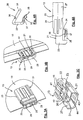
- FIGS. 7 to 10 a designed as a flat plate, for example as a motor vehicle license plate
- carrier 101 which carries on one of its flat sides an electroluminescent lighting assembly 103, which in section of the FIGS. 9 and 10 although it is actually made up of at least four layers, namely a metallically conductive base electrode (which may also be formed by the metal shield itself) of an insulating layer, a pigmentary layer emitting in operation the electroluminescent light, and one in comparison to FIGS other layers of extremely thin, metallically conductive, transparent cover electrode.
- a metallically conductive base electrode which may also be formed by the metal shield itself
- a pigmentary layer emitting in operation the electroluminescent light
- This contacting arrangement 105 has two plug elements 106, 107, of which the plug element 106, as in particular the FIGS. 9 and 10 removes, has a cross-sectionally approximately C-shaped body 108 made of an electrically insulating material which can be pushed onto the support 101 and fixedly connected to it so that it encompasses one of the edges of the carrier 101 with its two legs 101, 111 ,
- an outwardly open cavity 112 is formed in the one penetrating part 114 of the likewise made of an electrically insulating material body 113 of the female plug connector formed as a second plug element 107 can be inserted.
- the shapes of the cavity 112 and the penetrating part 114 are adapted to each other so that the cavity 112 is substantially filled in the assembled state by the penetrating part 114, wherein a provided on the outer peripheral surface of the penetrating part 114 seal 115 for a moisture and dustproof closure ensures.
- latching devices 117, 118 are provided, which hold the two plug elements 106, 107 in the assembled state, although firmly connected in a detachable manner.
- the electroluminescent lighting assembly 103 is covered by a transparent protective layer 120, which provides not only for moisture and dust protection of the electroluminescent lighting assembly 103 but also for a contact protection.
- the carrier 109 is made of an electrically conductive material, it is coated on all sides with this protective layer 120.
- the transparent protective layer 120 also closes the free space present between the legs 110, 111 of the plug element 106 and the carrier 109 in the assembled state, so that the electrical contacts located there, which are explained in more detail below, are protected against the ingress of moisture and dirt ,
- a cable 122 Connected to the plug element 107 is a cable 122, the wires (not shown) of which serve for the current / voltage supply of the electroluminescent lighting arrangement 103.
- the electroluminescent light-emitting arrangement 103 can include one or more flat capacitors, which, if desired, can also be controlled separately from one another. In the simplest case, all flat capacitors have one common base electrode and separate cover electrodes, each of which then must be connected to its own control line to allow separate operation. In the exemplary embodiment of the contacting arrangement 105 described here, it is assumed that only a flat capacitor with a base electrode and a cover electrode has to be supplied with current or voltage, for which purpose two electrically conductive connections to the associated electronic supply circuit are sufficient. It is clear to the person skilled in the art that at least one further electrically conductive connection to the electronic supply circuit is required for each further shed capacitor provided on the carrier 101. These further compounds are then constructed in an analogous manner as the connection connections described below.
- FIGS. 9 and 10 In order to control the flat capacitor of the electroluminescent light-emitting arrangement 103, are on in the FIGS. 9 and 10 At the top of the carrier 101 next to the electroluminescent light-emitting arrangement 103, two metallic contact surfaces 124 not covered by the protective layer 120 are provided, which in a sectional plane of FIG FIG. 9 or 10 perpendicular direction are behind each other, so that only one of them is visible, for example, with the base electrode (not shown) of the flat capacitor of the electroluminescent light assembly 103 in electrically conductive connection, while the second (not visible) contact surface with the transparent Cover electrode (not shown) of the flat capacitor is electrically connected.
- FIGS. 9, 10 Inside the body 108 of the first connector element 106 are a plurality of the FIGS. 9, 10 also provided C-shaped Porterlemente whose number is equal to the number of Contact surfaces of the electroluminescent lighting assembly 103 is. From these in the direction of the FIGS. 9 and 10 likewise one behind the other conductor elements is only one visible. The other conductor elements are formed in the same way.
- the in the FIGS. 9 and 10 overhead C-leg of the conductor element 126 serves as a contact element 128 for the contact surfaces 124, against which it is resiliently pressed in the assembled state.
- a contact element 128 against the body 108 of the plug member 106 in a direction perpendicular to the surface of the carrier 101 direction movable or the entire plug member 106 may be formed elastically. It is essential that in the plugged state, the lower surface of the contact element 128 is pressed against the contact surface 124 with a sufficient contact pressure.
- the lower of the two legs of the conductor element 126 is formed as a plug connection element 130 which projects in the form of a pin into the cavity 112 of the lower leg 111 of the plug element 106.
- Each of the female connectors 132 is in electrical contact with a wire of the cable 122 to provide power / voltage to the electroluminescent lighting assembly 103.
- the electronic power supply circuit required to operate the electroluminescent light assembly 103 may be positioned at different locations.
- the wires of the cable 122 are connected to the outputs of this supply circuit, so that about them, the connector elements 132, 130, the Porterlemente 126 and the contact elements 128 forming upper C-leg of the electroluminescent lighting assembly 103 required for their operation AC voltage is supplied, which is derived in the case that the carrier 101 is the license plate of a motor vehicle, with the aid of the electronic power supply circuit from the on-board DC voltage of the motor vehicle.
- the cable 122 and the plug elements 106, 107 must be designed, in particular in the region of their plug connection elements 130, 132, in such a way that they are suitable for these alternating voltages lying in the range of 90-120 V and also safe to touch in the separated state.
- the electronic supply circuit (not shown) into the second plug element 107 such that it lies between the wires of the cable 122 and the plug connection elements 132 of the plug element 107 and only the on-board DC voltage must be supplied via the cable 122.
- the requirements with regard to the dielectric strength and contact safety of the plug-in connection elements 130, 132 do not change as a result.
- Another possibility is to integrate the electronic supply voltage into the plug element 106.
- the continuous conductor elements 126 instead of the continuous conductor elements 126 then separate plug connection elements 130 and contact elements 128 are provided, between which the electronic supply circuit is connected.
- the plug elements 130, 132 then only have to be suitable for the forwarding of the low supply DC voltage. A special contact safety of the plug elements 106, 107 is then no longer necessary.
- the electronic supply circuit is integrated in one of the two plug elements 106, 107, it is preferably formed as an integrated circuit, wherein the semiconductor chip carrying it is mounted in a known manner on a leadframe, the connecting legs preferably directly penetrate Form plug connectors and thus can replace the contact pins 130.
- the receiving plug connection elements are provided on the plug element 106.
- the receiving cavity instead of the plug element 106 may be provided on the plug element 107, in which case the plug element 106 a corresponding penetrating part includes.
- the penetrating plug connection elements can be provided on the plug element 107 and the receiving plug connection elements on the plug element 106.
- the seal 115 may be fastened to the plug element 106 or formed in one piece with it. It is also possible to insert the seal 115 as an independent element to be handled separately between the plug elements 106 and 107.
Landscapes
- Details Of Connecting Devices For Male And Female Coupling (AREA)
- Lighting Device Outwards From Vehicle And Optical Signal (AREA)
- Connector Housings Or Holding Contact Members (AREA)
- Multi-Conductor Connections (AREA)
- Auxiliary Devices For And Details Of Packaging Control (AREA)
- Coupling Device And Connection With Printed Circuit (AREA)
Claims (10)
- Agencement de mise en contact (11, 105) pour fournir la tension alternative de service engendrée à partir d'une tension continue par un circuit d'alimentation, à un agencement d'éclairage à électroluminescence (103), qui comprend au moins un condensateur plat appliqué sur une surface d'une plaque-support (10, 101) avec une électrode de base, une couche d'isolation, une couche pigmentée lumineuse en fonctionnement, et une électrode de couverture transparente électroconductrice, ainsi qu'une couche de protection transparente (120), électriquement isolante et couvrant le condensateur plat, dans lequel sur une surface de la plaque-support (10, 101) sont prévues au moins deux surfaces de contact électroconductrices (16, 124) agencées l'une à côté de l'autre, non recouvertes par la couche de protection (120) électriquement isolante, parmi lesquelles l'une des surfaces de contact est électriquement reliée à l'électrode de base et l'autre est électriquement reliée à l'électrode de couverture dudit au moins un condensateur plat, dans lequel un élément enfichable (13, 106) est prévu du côté de la plaque-support, celui-ci comprenant un corps (13, 106) en matériau isolant, au moins deux éléments de contact (37, 128) électroconducteurs, et au moins deux éléments de connexion enfichables (31, 130) électroconducteurs, et étant monté sur la plaque-support (10, 101) de l'agencement d'éclairage à électroluminescence (103) de telle façon que l'un de ses éléments de contact (37, 128) respectif est engagé avec l'une des surfaces de contact (16, 124) de l'agencement d'éclairage à électroluminescence (103) d'une manière électroconductrice,
caractérisé en ce que le corps de l'élément enfichable (21, 108) recouvre les éléments de contact et les surfaces de contact de manière à les protéger vis-à-vis d'un contact physique. - Agencement de mise en contact selon la revendication 1, caractérisé en ce qu'il est prévu un élément enfichable (14, 107) du côté tension, susceptible d'être assemblé à l'élément enfichable (13, 106) du côté de la plaque-support et relié de manière électroconductrice avec les fils d'un câble d'alimentation électrique (15, 122), ledit élément enfichable (14, 107) comprenant au moins deux éléments de connexion enfichables électroconducteurs (51, 132) parmi lesquels, à l'état assemblé, un élément respectif est en engagement électroconducteur avec un élément de connexion enfichable de l'élément enfichable (6) du côté de la plaque-support.
- Agencement de mise en contact selon la revendication 1 ou 2, caractérisé en ce qu'une liaison électroconductrice directe respective est établie entre lesdits au moins deux éléments de contact (37, 128) de l'élément enfichable (13, 106) du côté de la plaque-support et ses au moins deux éléments de connexion enfichables (31, 130), en ce qu'une liaison électroconductrice directe est établie entre lesdits au moins deux éléments de connexions enfichables (51, 132), agencés de façon protégée vis-à-vis d'un contact physique dans le corps (31, 113) de l'élément enfichable (14, 107), et un fil respectif du câble d'alimentation électrique (15, 122) du côté tension, et en ce que les fils du câble d'alimentation électrique (15, 122) servent à l'amenée de la tension alternative de service fournie par le circuit d'alimentation.
- Agencement de mise en contact selon l'une au moins des revendications 1 à 3, caractérisé en ce que le circuit d'alimentation électronique est branché entre lesdits au moins deux éléments de contact (37, 128) et lesdits au moins deux éléments de connexion enfichables (31, 130) de l'élément enfichable (13, 106) du côté de la plaque-support, en ce qu'une liaison électroconductrice directe est établie entre lesdits au moins deux éléments de connexion enfichables (51, 132) de l'élément enfichable (14, 107) du côté tension et au moins deux fils du câble d'alimentation électrique (15, 122), et en ce que les fils du câble d'alimentation électrique (15, 122) servent à l'amenée de la tension continue au circuit d'alimentation.
- Agencement de mise en contact selon l'une au moins des revendications 1 à 3, caractérisé en ce qu'une liaison électroconductrice directe respective est établie entre lesdits au moins deux éléments de contact (37, 128) et lesdits au moins deux éléments de connexion enfichables (31, 130) de l'élément enfichable (13, 106) du côté de la plaque-support, et en ce que le circuit d'alimentation est branché entre les éléments de connexion enfichables (51, 132), agencés de façon protégée vis-à-vis d'un contact physique dans le corps (31, 113) de l'élément enfichable (14, 107) du côté tension, et les fils du câble d'alimentation électrique (15, 122) qui servent à l'amenée de la tension continue au circuit d'alimentation.
- Agencement de mise en contact selon l'une au moins des revendications 1 à 5, caractérisé en ce que l'élément enfichable (14, 107) du côté tension comprend une partie de pénétration, qui peut être introduite dans une cavité de réception de l'élément enfichable (13, 106) du côté support, pour établir un engagement électroconducteur entre l'élément de connexion enfichable (31, 130) de l'élément enfichable (13, 106) du côté support et les éléments de connexion enfichables (51, 132) de l'élément enfichable (14, 107) du côté tension.
- Agencement de mise en contact selon l'une au moins des revendications 1 à 5, caractérisé en ce que l'élément enfichable (13, 106) du côté support comprend une partie de pénétration, qui peut être introduite dans une cavité de réception de l'élément enfichable (14, 107), pour établir un engagement électroconducteur entre les éléments de connexion enfichables de l'élément enfichable (13, 106) du côté support et les éléments de connexion enfichables de l'élément enfichable (14, 104) du côté tension.
- Agencement de mise en contact (105) selon l'une au moins des revendications précédentes, pour un agencement d'éclairage à électroluminescence (103) dont la plaque-support (101) est réalisée sous forme de panneau, en particulier pour un panneau d'immatriculation de véhicule automobile auto-éclairant, caractérisé en ce que les surfaces de contact métalliques (124), sur la face antérieure du panneau qui porte l'agencement d'éclairage à électroluminescence (103), sont agencées au voisinage de sa bordure, et en ce que le corps (108) de l'élément enfichable (106) du côté de la plaque-support est réalisé avec une section transversale approximativement en forme de C, de telle façon qu'à l'état monté il coiffe le bord du panneau, en ce que les éléments de contact (128) disposés à nu sur le côté intérieur de l'une des branches (110) du C sont en contact électroconducteur avec les surfaces de contact (124) de l'agencement d'éclairage à électroluminescence (103), alors que les éléments de connexion enfichables (130) sont prévus sur la branche (111) du C qui se trouve à l'état monté sur le côté postérieur du panneau.
- Agencement de mise en contact selon l'une des revendications précédentes, caractérisé en ce que la couche protectrice transparente (120) contribue à l'étanchement anti-humidité et anti-poussière des interstices entre l'élément enfichable (106) du côté de la plaque-support et la plaque-support (1).
- Agencement de mise en contact selon l'une des revendications précédentes, caractérisé en ce que les éléments de contact (128) de l'élément enfichable (106) du côté support sont réalisés avec un effet ressort, de telle façon que, dans l'état assemblé, ils s'appliquent avec une force minimum définie sur les surfaces de contact (124) de l'agencement d'éclairage à électroluminescence (103).
Applications Claiming Priority (3)
| Application Number | Priority Date | Filing Date | Title |
|---|---|---|---|
| DE20306921U DE20306921U1 (de) | 2003-05-05 | 2003-05-05 | Kontaktierungsanordnung |
| DE10338981 | 2003-08-19 | ||
| PCT/EP2004/004733 WO2004100318A1 (fr) | 2003-05-05 | 2004-05-04 | Ensemble d'etablissement de contact |
Publications (2)
| Publication Number | Publication Date |
|---|---|
| EP1620926A1 EP1620926A1 (fr) | 2006-02-01 |
| EP1620926B1 true EP1620926B1 (fr) | 2008-07-23 |
Family
ID=33435987
Family Applications (2)
| Application Number | Title | Priority Date | Filing Date |
|---|---|---|---|
| EP04730994A Withdrawn EP1642363A2 (fr) | 2003-05-05 | 2004-05-04 | Systeme de connexion electrique male-femelle |
| EP04730976A Expired - Lifetime EP1620926B1 (fr) | 2003-05-05 | 2004-05-04 | Ensemble d'etablissement de contact |
Family Applications Before (1)
| Application Number | Title | Priority Date | Filing Date |
|---|---|---|---|
| EP04730994A Withdrawn EP1642363A2 (fr) | 2003-05-05 | 2004-05-04 | Systeme de connexion electrique male-femelle |
Country Status (5)
| Country | Link |
|---|---|
| US (2) | US7160139B2 (fr) |
| EP (2) | EP1642363A2 (fr) |
| AT (1) | ATE402502T1 (fr) |
| DE (2) | DE102004022345B4 (fr) |
| WO (2) | WO2004100318A1 (fr) |
Families Citing this family (8)
| Publication number | Priority date | Publication date | Assignee | Title |
|---|---|---|---|---|
| DE102005009442A1 (de) * | 2005-03-02 | 2006-09-14 | Hirschmann Automotive Gmbh | Steckverbinder mit einer Crimp-Abdichtung und/oder einer Kabelhalterung |
| EP1911122A2 (fr) * | 2005-04-14 | 2008-04-16 | Fractus, S.A. | Assemblage de contact d'antenne |
| US8506327B2 (en) * | 2009-09-30 | 2013-08-13 | Eric Jol | Portable electronic devices with sealed connectors |
| US8246383B2 (en) | 2010-03-19 | 2012-08-21 | Apple Inc. | Sealed connectors for portable electronic devices |
| US9190746B2 (en) * | 2011-05-03 | 2015-11-17 | Cardioinsight Technologies, Inc. | High-voltage resistance for a connector attached to a circuit board |
| US9337593B2 (en) * | 2013-06-13 | 2016-05-10 | Intermountain Electronics, Inc. | Plug and receptacle assembly |
| EP3026760A1 (fr) * | 2014-11-27 | 2016-06-01 | odelo GmbH | Connexion enfichable directe destinée à la mise en contact électrique de supports de pistes conductrices souples dans des feux de véhicules |
| CN109185144B (zh) * | 2018-11-01 | 2020-11-13 | 珠海格力电器股份有限公司 | 一种密封结构及具有其的涡旋式空压机 |
Family Cites Families (23)
| Publication number | Priority date | Publication date | Assignee | Title |
|---|---|---|---|---|
| DE1217087B (de) * | 1961-04-07 | 1966-05-18 | Gen Motors Corp | Vorrichtung zur Anzeige einer oder mehrerer veraenderlicher Groessen |
| US3329851A (en) * | 1965-09-21 | 1967-07-04 | Jean L Braeutigam | Electrical connection devices for electroluminescent panels |
| US3509401A (en) * | 1967-08-24 | 1970-04-28 | Sylvania Electric Prod | Encapsulated electroluminescent device |
| IT975428B (it) * | 1972-10-31 | 1974-07-20 | Fiat Spa | Connettore stagno fra cavi e cir cuiti stampati |
| EP0137972A1 (fr) * | 1983-09-02 | 1985-04-24 | Microdot Inc. | Connecteur électrique |
| DE3410452A1 (de) * | 1984-03-22 | 1985-09-26 | Progress-Elektrogeräte Mauz & Pfeiffer GmbH & Co, 7000 Stuttgart | Lampentraeger |
| DE3437526A1 (de) * | 1984-10-12 | 1986-04-17 | Allied Corp., Morristown, N.J. | Steckverbinder fuer oberflaechenmontage |
| US5013967A (en) * | 1987-08-07 | 1991-05-07 | Mitsubishi Cable Industries Ltd. | Electroluminescence lamp and method of use thereof |
| US5383095A (en) * | 1993-10-29 | 1995-01-17 | The Whitaker Corporation | Circuit board and edge-mountable connector therefor, and method of preparing a circuit board edge |
| US5409397A (en) * | 1993-11-15 | 1995-04-25 | Environmental Associates, Inc. | Adapter plug |
| GB2293697B (en) * | 1994-09-15 | 1998-11-18 | Nokia Telecommunications Oy | Surface mount test point enabling hands free diagnostic testing of electronic circuits |
| US5938455A (en) * | 1996-05-15 | 1999-08-17 | Ford Motor Company | Three-dimensional molded circuit board having interlocking connections |
| US6083025A (en) * | 1997-03-05 | 2000-07-04 | Ryosei Electro-Circuit Systems Ltd. | Connector |
| US6315620B1 (en) * | 1997-04-24 | 2001-11-13 | Seagate Technology Llc | System, method, and device for a pre-loaded straddle mounted connector assembly |
| CA2228235A1 (fr) * | 1997-06-19 | 1998-12-19 | Thomas & Betts Corporation | Connecteur monoface de bords de plaquettes de circuits imprimes a montage cavalier de type ameliore |
| US5915997A (en) * | 1997-07-15 | 1999-06-29 | Lan-Jen; Tsang | Thin-type plug |
| DE29712954U1 (de) * | 1997-07-22 | 1997-10-16 | Fer Fahrzeugelektrik Gmbh | Kennzeichenschild für ein Kraftfahrzeug |
| JP3351999B2 (ja) * | 1997-08-28 | 2002-12-03 | ヒロセ電機株式会社 | 電気コネクタ |
| GB2340982A (en) * | 1998-08-28 | 2000-03-01 | Bernard Arthur Henshaw | Vehicle Registration Plate |
| PL194571B1 (pl) * | 1999-10-07 | 2007-06-29 | Zaklady Sprzetu Instalacyjnego | Złącze elektryczne nierozbieralne |
| JP4327328B2 (ja) * | 2000-04-04 | 2009-09-09 | ローム株式会社 | 回路基板とフレキシブルフラットケーブルの電気的接続構造 |
| US6309223B1 (en) * | 2000-06-13 | 2001-10-30 | Trw Inc. | Terminal assembly for flexible circuit strip |
| DE20117575U1 (de) * | 2001-10-26 | 2002-03-28 | Moser Helmut | Sandwichplatte mit beidseitigen Leuchtfeldern |
-
2004
- 2004-04-28 DE DE102004022345A patent/DE102004022345B4/de not_active Expired - Fee Related
- 2004-05-04 EP EP04730994A patent/EP1642363A2/fr not_active Withdrawn
- 2004-05-04 WO PCT/EP2004/004733 patent/WO2004100318A1/fr active IP Right Grant
- 2004-05-04 WO PCT/EP2004/004711 patent/WO2004098954A2/fr active Application Filing
- 2004-05-04 AT AT04730976T patent/ATE402502T1/de not_active IP Right Cessation
- 2004-05-04 DE DE502004007679T patent/DE502004007679D1/de not_active Expired - Lifetime
- 2004-05-04 EP EP04730976A patent/EP1620926B1/fr not_active Expired - Lifetime
-
2005
- 2005-11-03 US US11/266,435 patent/US7160139B2/en not_active Expired - Fee Related
- 2005-11-09 US US11/270,420 patent/US7195496B2/en not_active Expired - Fee Related
Also Published As
| Publication number | Publication date |
|---|---|
| US20060073715A1 (en) | 2006-04-06 |
| EP1642363A2 (fr) | 2006-04-05 |
| DE102004022345B4 (de) | 2006-02-09 |
| EP1620926A1 (fr) | 2006-02-01 |
| US7195496B2 (en) | 2007-03-27 |
| US7160139B2 (en) | 2007-01-09 |
| US20060094282A1 (en) | 2006-05-04 |
| WO2004098954A3 (fr) | 2005-05-26 |
| DE102004022345A1 (de) | 2004-12-16 |
| ATE402502T1 (de) | 2008-08-15 |
| DE502004007679D1 (de) | 2008-09-04 |
| WO2004098954A2 (fr) | 2004-11-18 |
| WO2004100318A1 (fr) | 2004-11-18 |
Similar Documents
| Publication | Publication Date | Title |
|---|---|---|
| EP0678932B1 (fr) | Borne de raccordement et de connexion électrique | |
| DE19513949C2 (de) | Verfahren zur Herstellung eines Kunstharzteiles mit einem eingeformten Metallteilsatz | |
| DE19549519B4 (de) | Elektrischer Steckverbinder | |
| DE102004038123B4 (de) | Elektrischer Stecker und elektrische Steckeraufnahme | |
| EP0212330B1 (fr) | Borne de jonction ou serre-fil pour appareils électriques | |
| DE10012387C2 (de) | Anordnung zum Verbinden eines Kabels mit einem Kraftfahrzeugbatteriepol | |
| DE19813458A1 (de) | Elektrischer Verbinder | |
| DE4408569C2 (de) | Elektrischer Verbinder mit Kurzschließmöglichkeit | |
| DE19848554A1 (de) | Einen Schalter aufweisender Stecker | |
| DE102006019493A1 (de) | Druckschalter | |
| EP0368115A2 (fr) | Comprimé buccal | |
| EP0621661A2 (fr) | Socle pour appareillage électrique | |
| DE19857087C2 (de) | Elektrischer Verbinder für Kraftfahrzeugleuchte | |
| EP1620926B1 (fr) | Ensemble d'etablissement de contact | |
| DE102019000410B4 (de) | Leuchte und Adapter für Leuchte | |
| DE10230292B3 (de) | Träger für Modulgehäuse | |
| DE3014490C2 (de) | Elektrischer Schalter mit Beleuchtungseinrichtung | |
| DE19916949A1 (de) | Gehäuse, insbesondere Schloßgehäuse für einen Kraftfahrzeugtürverschluß, Getriebegehäuse oder dergleichen Leitungsträger | |
| DE102005005705A1 (de) | Kontaktierungsmittel für flexible elektrische Flachbandkabel | |
| DE3306219C2 (de) | Schalter, insbesondere für Kraftfahrzeuge | |
| DE8420661U1 (de) | Elektrischer Hilfsanschluss | |
| DE3319231A1 (de) | Beleuchtungseinrichtung | |
| DE102014012459A1 (de) | Elektronische Baueinheit, insbesondere kapazitiver Näherungssensor für ein Fahrzeug | |
| DE4408369C2 (de) | Halter für eine Lampe | |
| DE4405760A1 (de) | Leuchtmittel sowie beleuchtbarer elektrischer Schalter |
Legal Events
| Date | Code | Title | Description |
|---|---|---|---|
| PUAI | Public reference made under article 153(3) epc to a published international application that has entered the european phase |
Free format text: ORIGINAL CODE: 0009012 |
|
| 17P | Request for examination filed |
Effective date: 20050924 |
|
| AK | Designated contracting states |
Kind code of ref document: A1 Designated state(s): AT BE BG CH CY CZ DE DK EE ES FI FR GB GR HU IE IT LI LU MC NL PL PT RO SE SI SK TR |
|
| DAX | Request for extension of the european patent (deleted) | ||
| GRAP | Despatch of communication of intention to grant a patent |
Free format text: ORIGINAL CODE: EPIDOSNIGR1 |
|
| GRAS | Grant fee paid |
Free format text: ORIGINAL CODE: EPIDOSNIGR3 |
|
| GRAA | (expected) grant |
Free format text: ORIGINAL CODE: 0009210 |
|
| AK | Designated contracting states |
Kind code of ref document: B1 Designated state(s): AT BE BG CH CY CZ DE DK EE ES FI FR GB GR HU IE IT LI LU MC NL PL PT RO SE SI SK TR |
|
| REG | Reference to a national code |
Ref country code: GB Ref legal event code: FG4D Free format text: NOT ENGLISH |
|
| REG | Reference to a national code |
Ref country code: CH Ref legal event code: EP |
|
| REG | Reference to a national code |
Ref country code: IE Ref legal event code: FG4D Free format text: LANGUAGE OF EP DOCUMENT: GERMAN |
|
| REF | Corresponds to: |
Ref document number: 502004007679 Country of ref document: DE Date of ref document: 20080904 Kind code of ref document: P |
|
| NLV1 | Nl: lapsed or annulled due to failure to fulfill the requirements of art. 29p and 29m of the patents act | ||
| PG25 | Lapsed in a contracting state [announced via postgrant information from national office to epo] |
Ref country code: ES Free format text: LAPSE BECAUSE OF FAILURE TO SUBMIT A TRANSLATION OF THE DESCRIPTION OR TO PAY THE FEE WITHIN THE PRESCRIBED TIME-LIMIT Effective date: 20081103 Ref country code: NL Free format text: LAPSE BECAUSE OF FAILURE TO SUBMIT A TRANSLATION OF THE DESCRIPTION OR TO PAY THE FEE WITHIN THE PRESCRIBED TIME-LIMIT Effective date: 20080723 Ref country code: PT Free format text: LAPSE BECAUSE OF FAILURE TO SUBMIT A TRANSLATION OF THE DESCRIPTION OR TO PAY THE FEE WITHIN THE PRESCRIBED TIME-LIMIT Effective date: 20081223 |
|
| PG25 | Lapsed in a contracting state [announced via postgrant information from national office to epo] |
Ref country code: FI Free format text: LAPSE BECAUSE OF FAILURE TO SUBMIT A TRANSLATION OF THE DESCRIPTION OR TO PAY THE FEE WITHIN THE PRESCRIBED TIME-LIMIT Effective date: 20080723 Ref country code: BG Free format text: LAPSE BECAUSE OF FAILURE TO SUBMIT A TRANSLATION OF THE DESCRIPTION OR TO PAY THE FEE WITHIN THE PRESCRIBED TIME-LIMIT Effective date: 20081023 Ref country code: SI Free format text: LAPSE BECAUSE OF FAILURE TO SUBMIT A TRANSLATION OF THE DESCRIPTION OR TO PAY THE FEE WITHIN THE PRESCRIBED TIME-LIMIT Effective date: 20080723 |
|
| REG | Reference to a national code |
Ref country code: IE Ref legal event code: FD4D |
|
| PG25 | Lapsed in a contracting state [announced via postgrant information from national office to epo] |
Ref country code: IE Free format text: LAPSE BECAUSE OF FAILURE TO SUBMIT A TRANSLATION OF THE DESCRIPTION OR TO PAY THE FEE WITHIN THE PRESCRIBED TIME-LIMIT Effective date: 20080723 Ref country code: EE Free format text: LAPSE BECAUSE OF FAILURE TO SUBMIT A TRANSLATION OF THE DESCRIPTION OR TO PAY THE FEE WITHIN THE PRESCRIBED TIME-LIMIT Effective date: 20080723 Ref country code: DK Free format text: LAPSE BECAUSE OF FAILURE TO SUBMIT A TRANSLATION OF THE DESCRIPTION OR TO PAY THE FEE WITHIN THE PRESCRIBED TIME-LIMIT Effective date: 20080723 |
|
| PG25 | Lapsed in a contracting state [announced via postgrant information from national office to epo] |
Ref country code: SK Free format text: LAPSE BECAUSE OF FAILURE TO SUBMIT A TRANSLATION OF THE DESCRIPTION OR TO PAY THE FEE WITHIN THE PRESCRIBED TIME-LIMIT Effective date: 20080723 Ref country code: CZ Free format text: LAPSE BECAUSE OF FAILURE TO SUBMIT A TRANSLATION OF THE DESCRIPTION OR TO PAY THE FEE WITHIN THE PRESCRIBED TIME-LIMIT Effective date: 20080723 Ref country code: RO Free format text: LAPSE BECAUSE OF FAILURE TO SUBMIT A TRANSLATION OF THE DESCRIPTION OR TO PAY THE FEE WITHIN THE PRESCRIBED TIME-LIMIT Effective date: 20080723 |
|
| PLBE | No opposition filed within time limit |
Free format text: ORIGINAL CODE: 0009261 |
|
| STAA | Information on the status of an ep patent application or granted ep patent |
Free format text: STATUS: NO OPPOSITION FILED WITHIN TIME LIMIT |
|
| 26N | No opposition filed |
Effective date: 20090424 |
|
| PG25 | Lapsed in a contracting state [announced via postgrant information from national office to epo] |
Ref country code: IT Free format text: LAPSE BECAUSE OF FAILURE TO SUBMIT A TRANSLATION OF THE DESCRIPTION OR TO PAY THE FEE WITHIN THE PRESCRIBED TIME-LIMIT Effective date: 20080723 |
|
| BERE | Be: lapsed |
Owner name: ITT MFG ENTERPRISES, INC. Effective date: 20090531 |
|
| PG25 | Lapsed in a contracting state [announced via postgrant information from national office to epo] |
Ref country code: MC Free format text: LAPSE BECAUSE OF NON-PAYMENT OF DUE FEES Effective date: 20090531 |
|
| REG | Reference to a national code |
Ref country code: CH Ref legal event code: PL |
|
| PG25 | Lapsed in a contracting state [announced via postgrant information from national office to epo] |
Ref country code: CH Free format text: LAPSE BECAUSE OF NON-PAYMENT OF DUE FEES Effective date: 20090531 Ref country code: LI Free format text: LAPSE BECAUSE OF NON-PAYMENT OF DUE FEES Effective date: 20090531 Ref country code: SE Free format text: LAPSE BECAUSE OF FAILURE TO SUBMIT A TRANSLATION OF THE DESCRIPTION OR TO PAY THE FEE WITHIN THE PRESCRIBED TIME-LIMIT Effective date: 20081023 |
|
| PG25 | Lapsed in a contracting state [announced via postgrant information from national office to epo] |
Ref country code: PL Free format text: LAPSE BECAUSE OF FAILURE TO SUBMIT A TRANSLATION OF THE DESCRIPTION OR TO PAY THE FEE WITHIN THE PRESCRIBED TIME-LIMIT Effective date: 20080723 |
|
| PG25 | Lapsed in a contracting state [announced via postgrant information from national office to epo] |
Ref country code: BE Free format text: LAPSE BECAUSE OF NON-PAYMENT OF DUE FEES Effective date: 20090531 |
|
| PG25 | Lapsed in a contracting state [announced via postgrant information from national office to epo] |
Ref country code: AT Free format text: LAPSE BECAUSE OF NON-PAYMENT OF DUE FEES Effective date: 20090504 |
|
| PG25 | Lapsed in a contracting state [announced via postgrant information from national office to epo] |
Ref country code: GR Free format text: LAPSE BECAUSE OF FAILURE TO SUBMIT A TRANSLATION OF THE DESCRIPTION OR TO PAY THE FEE WITHIN THE PRESCRIBED TIME-LIMIT Effective date: 20081024 |
|
| PG25 | Lapsed in a contracting state [announced via postgrant information from national office to epo] |
Ref country code: LU Free format text: LAPSE BECAUSE OF NON-PAYMENT OF DUE FEES Effective date: 20090504 |
|
| PG25 | Lapsed in a contracting state [announced via postgrant information from national office to epo] |
Ref country code: HU Free format text: LAPSE BECAUSE OF FAILURE TO SUBMIT A TRANSLATION OF THE DESCRIPTION OR TO PAY THE FEE WITHIN THE PRESCRIBED TIME-LIMIT Effective date: 20090124 |
|
| PG25 | Lapsed in a contracting state [announced via postgrant information from national office to epo] |
Ref country code: TR Free format text: LAPSE BECAUSE OF FAILURE TO SUBMIT A TRANSLATION OF THE DESCRIPTION OR TO PAY THE FEE WITHIN THE PRESCRIBED TIME-LIMIT Effective date: 20080723 |
|
| PG25 | Lapsed in a contracting state [announced via postgrant information from national office to epo] |
Ref country code: CY Free format text: LAPSE BECAUSE OF FAILURE TO SUBMIT A TRANSLATION OF THE DESCRIPTION OR TO PAY THE FEE WITHIN THE PRESCRIBED TIME-LIMIT Effective date: 20080723 |
|
| PGFP | Annual fee paid to national office [announced via postgrant information from national office to epo] |
Ref country code: DE Payment date: 20120529 Year of fee payment: 9 |
|
| PGFP | Annual fee paid to national office [announced via postgrant information from national office to epo] |
Ref country code: FR Payment date: 20120607 Year of fee payment: 9 Ref country code: GB Payment date: 20120525 Year of fee payment: 9 |
|
| REG | Reference to a national code |
Ref country code: DE Ref legal event code: R119 Ref document number: 502004007679 Country of ref document: DE |
|
| GBPC | Gb: european patent ceased through non-payment of renewal fee |
Effective date: 20130504 |
|
| PG25 | Lapsed in a contracting state [announced via postgrant information from national office to epo] |
Ref country code: DE Free format text: LAPSE BECAUSE OF NON-PAYMENT OF DUE FEES Effective date: 20131203 |
|
| REG | Reference to a national code |
Ref country code: FR Ref legal event code: ST Effective date: 20140131 |
|
| PG25 | Lapsed in a contracting state [announced via postgrant information from national office to epo] |
Ref country code: GB Free format text: LAPSE BECAUSE OF NON-PAYMENT OF DUE FEES Effective date: 20130504 |
|
| REG | Reference to a national code |
Ref country code: DE Ref legal event code: R079 Ref document number: 502004007679 Country of ref document: DE Free format text: PREVIOUS MAIN CLASS: H01R0012180000 Ipc: H01R0012500000 |
|
| PG25 | Lapsed in a contracting state [announced via postgrant information from national office to epo] |
Ref country code: FR Free format text: LAPSE BECAUSE OF NON-PAYMENT OF DUE FEES Effective date: 20130531 |
|
| REG | Reference to a national code |
Ref country code: DE Ref legal event code: R119 Ref document number: 502004007679 Country of ref document: DE Effective date: 20131203 Ref country code: DE Ref legal event code: R079 Ref document number: 502004007679 Country of ref document: DE Free format text: PREVIOUS MAIN CLASS: H01R0012180000 Ipc: H01R0012500000 Effective date: 20140523 |