EP1620926B1 - Contact assembly - Google Patents
Contact assembly Download PDFInfo
- Publication number
- EP1620926B1 EP1620926B1 EP04730976A EP04730976A EP1620926B1 EP 1620926 B1 EP1620926 B1 EP 1620926B1 EP 04730976 A EP04730976 A EP 04730976A EP 04730976 A EP04730976 A EP 04730976A EP 1620926 B1 EP1620926 B1 EP 1620926B1
- Authority
- EP
- European Patent Office
- Prior art keywords
- plug
- contact
- plug element
- electrically conductive
- elements
- Prior art date
- Legal status (The legal status is an assumption and is not a legal conclusion. Google has not performed a legal analysis and makes no representation as to the accuracy of the status listed.)
- Expired - Lifetime
Links
- 230000000149 penetrating effect Effects 0.000 claims description 14
- 239000003990 capacitor Substances 0.000 claims description 12
- 239000011241 protective layer Substances 0.000 claims description 9
- 239000002184 metal Substances 0.000 claims description 8
- 239000010410 layer Substances 0.000 claims description 7
- 239000000428 dust Substances 0.000 claims description 2
- 238000007789 sealing Methods 0.000 claims description 2
- 239000011810 insulating material Substances 0.000 claims 1
- 238000009413 insulation Methods 0.000 claims 1
- 239000000049 pigment Substances 0.000 claims 1
- 229920003023 plastic Polymers 0.000 abstract description 8
- 239000004033 plastic Substances 0.000 abstract description 8
- 239000004020 conductor Substances 0.000 abstract description 7
- 239000011324 bead Substances 0.000 description 6
- 230000008719 thickening Effects 0.000 description 4
- 239000012777 electrically insulating material Substances 0.000 description 3
- 230000000295 complement effect Effects 0.000 description 2
- 150000001875 compounds Chemical class 0.000 description 2
- 230000004913 activation Effects 0.000 description 1
- 238000010292 electrical insulation Methods 0.000 description 1
- 238000005538 encapsulation Methods 0.000 description 1
- 230000001747 exhibiting effect Effects 0.000 description 1
- 239000011888 foil Substances 0.000 description 1
- 238000005286 illumination Methods 0.000 description 1
- 238000001746 injection moulding Methods 0.000 description 1
- 238000004020 luminiscence type Methods 0.000 description 1
- 238000004519 manufacturing process Methods 0.000 description 1
- 239000000463 material Substances 0.000 description 1
- 230000002093 peripheral effect Effects 0.000 description 1
- 238000004382 potting Methods 0.000 description 1
- 239000004065 semiconductor Substances 0.000 description 1
Images


Classifications
-
- H—ELECTRICITY
- H01—ELECTRIC ELEMENTS
- H01R—ELECTRICALLY-CONDUCTIVE CONNECTIONS; STRUCTURAL ASSOCIATIONS OF A PLURALITY OF MUTUALLY-INSULATED ELECTRICAL CONNECTING ELEMENTS; COUPLING DEVICES; CURRENT COLLECTORS
- H01R12/00—Structural associations of a plurality of mutually-insulated electrical connecting elements, specially adapted for printed circuits, e.g. printed circuit boards [PCB], flat or ribbon cables, or like generally planar structures, e.g. terminal strips, terminal blocks; Coupling devices specially adapted for printed circuits, flat or ribbon cables, or like generally planar structures; Terminals specially adapted for contact with, or insertion into, printed circuits, flat or ribbon cables, or like generally planar structures
- H01R12/70—Coupling devices
- H01R12/7005—Guiding, mounting, polarizing or locking means; Extractors
- H01R12/7011—Locking or fixing a connector to a PCB
- H01R12/7058—Locking or fixing a connector to a PCB characterised by the movement, e.g. pivoting, camming or translating parallel to the PCB
-
- H—ELECTRICITY
- H01—ELECTRIC ELEMENTS
- H01R—ELECTRICALLY-CONDUCTIVE CONNECTIONS; STRUCTURAL ASSOCIATIONS OF A PLURALITY OF MUTUALLY-INSULATED ELECTRICAL CONNECTING ELEMENTS; COUPLING DEVICES; CURRENT COLLECTORS
- H01R12/00—Structural associations of a plurality of mutually-insulated electrical connecting elements, specially adapted for printed circuits, e.g. printed circuit boards [PCB], flat or ribbon cables, or like generally planar structures, e.g. terminal strips, terminal blocks; Coupling devices specially adapted for printed circuits, flat or ribbon cables, or like generally planar structures; Terminals specially adapted for contact with, or insertion into, printed circuits, flat or ribbon cables, or like generally planar structures
- H01R12/70—Coupling devices
- H01R12/71—Coupling devices for rigid printing circuits or like structures
- H01R12/72—Coupling devices for rigid printing circuits or like structures coupling with the edge of the rigid printed circuits or like structures
- H01R12/721—Coupling devices for rigid printing circuits or like structures coupling with the edge of the rigid printed circuits or like structures cooperating directly with the edge of the rigid printed circuits
Definitions
- the present invention relates to a contacting arrangement according to the preamble of claim 1.
- the carrier of the electroluminescent lighting arrangement is formed as a flat metal plate, which also serves as a base electrode of the at least one flat capacitor arrangement.
- the AC voltage required for the operation of the electroluminescent light assembly which is derived from an electronic supply circuit from the on-board DC voltage of the motor vehicle, is supplied to the electroluminescent light assembly via two spring contact elements, which is inserted between a holding frame, in which the metal shield is inserted, and the metal shield are arranged so that one is pressed against the back of the metal shield and the other against an arranged on the front side of the metal shield and insulated against this contact surface which is in electrically conductive connection with the cover electrode of the flat capacitor of the electroluminescent light assembly.
- the two spring contact elements are connected via connecting lines to the AC output of the electronic supply circuit.
- a contacting arrangement with a plug element according to the preamble of claim 1 is made US-A-3329851 known.
- the present invention seeks to provide a Kunststoffleitersan extract of the aforementioned type, which is designed completely safe to touch and even under harsh operating conditions ensures a permanently good power supply path from the DC voltage source to the electroluminescent lighting arrangement.
- the contacting arrangement comprises a plug member which is fixedly connected to the support plate of the electroluminescent light assembly so that its existing of an electrically insulating material body covers in particular the exposed contact surfaces of the otherwise coated with an electrically insulating protective layer electroluminescent light assembly safe to touch , eliminates the risk that in the manufacture of a connector and activation of the electronic power supply circuit, a comparatively high operating AC voltage leading part can be accidentally touched.
- the electronic power supply circuit at different locations of the power supply path leading from a source of low DC voltage to the electroluminescent lighting assembly that is, optionally between the DC voltage source and the associated plug element or between the connector connection elements and the contact elements of the carrier plate side connector element can be arranged, arise depending on the specific design of different requirements with respect to the contact safety of the other parts.
- the plug-in connection elements of the battery-side plug element must be accommodated in the insulating body in a manner that is safe to touch, which is readily possible, in particular if they are designed as receiving plug-in connection elements. In the second of the above cases, this is not necessary because then only the completely harmless, low DC voltage is passed on the connector elements of the two connector elements.
- the plug-in elements of the battery-side connector element as penetrating and the carrier plate side plug member as female connector elements, but then expediently the body of the carrier plate side plug member comprises a penetrating part and the body of the battery-side plug member comprises a receiving cavity in which the penetrating Plug connection elements are housed short-circuit proof.
- the two connector elements by means of complementary locking devices, but at any time releasably connected to each other, a connection possibility is created in particular for a motor vehicle license plate, both during initial assembly and when replacing the motor vehicle license plate can be attached and resolved in a simple and secure way.
- the support plate of the electroluminescent light assembly can be made of plastic or metal. In the latter case, it is required to achieve the touch safety, except for the first Steckerlement To cover covered contact surfaces on all sides with the already mentioned, insulating protective layer.
- the in the FIGS. 1 to 6 also referred to as electrical connector device contacting arrangement 11 is used according to the Figures 1A and 1B for attachment to a flat plate, here to a motor vehicle license plate 10, which is attached for example to the back of a car or truck.
- the motor vehicle license plate 10 is occupied on the visible side with a luminous foil 12 and not shown in detail electroluminescent light assembly surface, which is brought by applying to an electrical medium voltage, for example in the order of between about 140 volts and 200 volts AC voltage to light up.
- the connector device 11 according to the invention used for this purpose is designed in such a way that it can be mounted on the one hand substantially on the back and thus on the non-visible side of the plate 10 in a flat, little space engaging manner.
- the connector device 11 for example, when changing license plate or the like. Nevertheless, be easily solved.
- the connector device 11 is therefore composed of a male connector 13 which can be mechanically latched and electrically conductively attached to an edge region of the plate 10, and a female connector 14 which is equipped with a connecting cable 15 and with the male connector 13 mechanically latching and electrically releasably pluggable can be connected.
- the male connector 13 has a housing 21 which is integrally formed by a front housing part 22 for connecting to the plate 10 and a rear housing part 23 for plug-in connection with the female connector 14.
- the front housing part 22 is in side view of FIG. 4 Seen approximately C-shaped, that is, it has a receiving slot 24 for receiving the respective edge portion 19 of the plate 10.
- the receiving slot 24 relative to the transverse center axis of the Housing 21 and the front housing part 22 arranged asymmetrically, ie, that the receiving slot 24 limiting upper or view-side wall 25 is relatively thin.
- the rear housing part 23, which is arranged in the attached state on the plate 10 only on the visible side facing away from the rear plate has a round closed connector receptacle 26 and a half-shell, open to the license plate rear connector guide 27.
- In the receiving slot are on the side facing away from the visible side grooves 42 provided, which facilitate the material flow during subsequent injection molding.
- On the opposite side guide webs 45 are provided which can be inserted into the slots 19 of the motor vehicle license plate.
- the housing 21 of the male connector 13 includes a plurality of contact pins 28 and 29.
- the contact pins 28 and 29 are pressed into the housing 21 made of plastic or latched inserted or otherwise secured.
- the housing 21 is pushed onto the flat plate 10 ( Fig. 3A ) and in this position with a dash-dotted lines indicated plastic jacket 30 encapsulated or molded ( Fig. 3B ).
- One of the two contact pins 28 is in FIG. 4B shown.
- the contact pin 28 has a cylindrical pin-shaped end 31 which is located in the female connector receptacle 26, a flattened end 32 which is located in the upper wall 25 and in the receiving slot 24, and a perpendicular thereto arranged connecting part 33, the contact pin 28th gives a Klammerartiges or appearing as U lying appearance.
- the housing 21 of the male connector 13 receives a contact pin 28 on both outer side regions.
- Two U-shaped electrically and mechanically interconnected contact pins 29 are arranged centrally, wherein the cylindrical pin-shaped Ends within the female connector receptacle 26 are arranged.
- the upper or visible side of the motor vehicle license plate 10 has according to FIG. 2 at a longitudinal end of the luminous film 12 in a symmetrical arrangement to its longitudinal axis two spaced contacting regions 16 which are electrically connected to the luminous sheet 12. Furthermore, the license plate or the license plate 10 has a latching recess 17 between the two contacting areas 16, into which a latching hook 41 arranged on the plug connector housing 21 FIG.
- the contact pins 28 have for fixing in the housing 21 at its cylindrical end 31, for example.
- the adjoining the connecting part 33 flattened end 32 is the cylindrical end 31 opposite convexly curved, so that there is a raised apex portion 37.
- the apex region 37 is also arched in the transverse direction, so that a spherical region in the form of a contact point 38 results.
- the contact pins 28 are disposed within the housing 21 and the front housing part 22 that the apex portion 37 and the spherical contact point 38 of the flat pin end 32 protrudes out of a recess in the upper wall 25, into the receiving slot 24 , Since the flat contact pin end 32 is elastically resilient, this results in the attachment of the pin connector 13 on the plate 10, a certain contact pressure to improve the contact with the Contacting areas 16 of the luminous film 12 on the plate 10th
- the pin connector 13 carries little attached to the front or visible side of the motor vehicle license plate 10 when plugged.
- the female connector 27 of the male connector housing 21 is open to the back of the license plate 10, wherein the height of the side wall of the female connector guide 27 corresponds approximately to the height or thickness of the female connector receptacle 26.
- the socket connector guide 27 has centrally and in the longitudinal direction of a latching hook 43, which, as will be described later, serves for latching connection with the female connector 14.
- the female connector 14 itself engages in the receptacle 26, wherein an electrical contact of the respective electrical contacts 51 and 28, 29 of female connector 14 and male connector 13 is reached.
- a protruding coding element 44 may be provided, which engages in a coding receptacle 54 on the female connector 14.
- the female connector 14 is in the FIGS. 5 and 6 shown in detail.
- the female connector 14 here has four female contacts or sleeves 51 which are suitably mechanically and electrically connected at their rear end to the wires 52 of the stripped cable 15 in a suitable manner.
- a ring 53 is arranged for strain relief.
- the contact sockets 51 are inserted and held with their rear end in a two-half shells 56, 56a existing, for example, on one side longitudinally provided with a film hinge and on the opposite side corresponding locking means exhibiting hard housing part.
- On the first hard housing part 56 is also a latch hook 57 ( Fig.
- the first housing part 56 is made of a hard mechanically stable plastic.
- the protruding contacts 51, the first housing part 56 and the remaining part of the wires 52 and a longitudinal portion of the non-insulated cable 15 are encapsulated by a second housing part 58, which consists of a relatively soft plastic.
- the second soft housing part 58 has circumferential sealing lips 59 surrounding the projecting contacts 51 in a front region 59, which ensure a moisture-proof connection between the female connector 14 and the male connector 13.
- the second housing part 58 is provided with a recess 61 through which the latching hook 57 protrudes.
- a bead 62 can be seen longitudinally, in which the non-stripped cable 15 and the strain relief ring 53 are kept encapsulated.
- This bead 62 is part of a handle portion 63 of the second housing part 58.
- This handle portion 63 further has two arranged on both sides of the bead 62 handle wing 64, which are rounded outside edge and have a thickening 66, which end at the end of the bead 62 and in one area start behind the latch hook 57.
- the thickenings 66 may be thinner or approximately correspond to the bead 62, wherein the intermediate region between the longitudinal axis forming bead 62 and the two outer wall side thickenings 66 of the handle wing 64 has a thinner wall.
- the two gripping wings 64 are arranged in an acute-angled position to the plane of the two housing parts 56 and 58, wherein both gripping wings 64 in the same direction according to FIG. 1B tilted away from the license plate back.
- the two handle wings 64 are due to the relatively soft plastic of the second housing part 58 in Direction of the arrows G bendable or movable, this can preferably be done elastically restoring. This bendability is of particular advantage when the female connector 14 according to Figure 1A placed in the pin connector 13 and locked.
- the grip area 63 is thus substantially as flat as the pin plug 13 on the back of the plate 10.
- the grip wing 64 detected at the edge-side thickening 66 and further moved toward each other in the direction of arrows G or be bent. This turn off from the back of the plate 10 away ( Fig. 1B ). With the successive movement of the handle wings 64, the grip area 63 can be detected perpendicular to the license plate and clamping between the fingers. In this way, the female connector 14 can be easily pulled out of the male connector 13.
- the connector device 11, two U-shaped and two elongated pins 28 and 29 are described, it is understood that the number of these side by side and parallel to the plate 10 for obtaining a flat connector device 11 arranged contact pins can be changed.
- the plug 13 may be formed as a female connector and the plug 14 as a male connector.
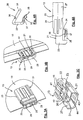
- FIGS. 7 to 10 a designed as a flat plate, for example as a motor vehicle license plate
- carrier 101 which carries on one of its flat sides an electroluminescent lighting assembly 103, which in section of the FIGS. 9 and 10 although it is actually made up of at least four layers, namely a metallically conductive base electrode (which may also be formed by the metal shield itself) of an insulating layer, a pigmentary layer emitting in operation the electroluminescent light, and one in comparison to FIGS other layers of extremely thin, metallically conductive, transparent cover electrode.
- a metallically conductive base electrode which may also be formed by the metal shield itself
- a pigmentary layer emitting in operation the electroluminescent light
- This contacting arrangement 105 has two plug elements 106, 107, of which the plug element 106, as in particular the FIGS. 9 and 10 removes, has a cross-sectionally approximately C-shaped body 108 made of an electrically insulating material which can be pushed onto the support 101 and fixedly connected to it so that it encompasses one of the edges of the carrier 101 with its two legs 101, 111 ,
- an outwardly open cavity 112 is formed in the one penetrating part 114 of the likewise made of an electrically insulating material body 113 of the female plug connector formed as a second plug element 107 can be inserted.
- the shapes of the cavity 112 and the penetrating part 114 are adapted to each other so that the cavity 112 is substantially filled in the assembled state by the penetrating part 114, wherein a provided on the outer peripheral surface of the penetrating part 114 seal 115 for a moisture and dustproof closure ensures.
- latching devices 117, 118 are provided, which hold the two plug elements 106, 107 in the assembled state, although firmly connected in a detachable manner.
- the electroluminescent lighting assembly 103 is covered by a transparent protective layer 120, which provides not only for moisture and dust protection of the electroluminescent lighting assembly 103 but also for a contact protection.
- the carrier 109 is made of an electrically conductive material, it is coated on all sides with this protective layer 120.
- the transparent protective layer 120 also closes the free space present between the legs 110, 111 of the plug element 106 and the carrier 109 in the assembled state, so that the electrical contacts located there, which are explained in more detail below, are protected against the ingress of moisture and dirt ,
- a cable 122 Connected to the plug element 107 is a cable 122, the wires (not shown) of which serve for the current / voltage supply of the electroluminescent lighting arrangement 103.
- the electroluminescent light-emitting arrangement 103 can include one or more flat capacitors, which, if desired, can also be controlled separately from one another. In the simplest case, all flat capacitors have one common base electrode and separate cover electrodes, each of which then must be connected to its own control line to allow separate operation. In the exemplary embodiment of the contacting arrangement 105 described here, it is assumed that only a flat capacitor with a base electrode and a cover electrode has to be supplied with current or voltage, for which purpose two electrically conductive connections to the associated electronic supply circuit are sufficient. It is clear to the person skilled in the art that at least one further electrically conductive connection to the electronic supply circuit is required for each further shed capacitor provided on the carrier 101. These further compounds are then constructed in an analogous manner as the connection connections described below.
- FIGS. 9 and 10 In order to control the flat capacitor of the electroluminescent light-emitting arrangement 103, are on in the FIGS. 9 and 10 At the top of the carrier 101 next to the electroluminescent light-emitting arrangement 103, two metallic contact surfaces 124 not covered by the protective layer 120 are provided, which in a sectional plane of FIG FIG. 9 or 10 perpendicular direction are behind each other, so that only one of them is visible, for example, with the base electrode (not shown) of the flat capacitor of the electroluminescent light assembly 103 in electrically conductive connection, while the second (not visible) contact surface with the transparent Cover electrode (not shown) of the flat capacitor is electrically connected.
- FIGS. 9, 10 Inside the body 108 of the first connector element 106 are a plurality of the FIGS. 9, 10 also provided C-shaped Porterlemente whose number is equal to the number of Contact surfaces of the electroluminescent lighting assembly 103 is. From these in the direction of the FIGS. 9 and 10 likewise one behind the other conductor elements is only one visible. The other conductor elements are formed in the same way.
- the in the FIGS. 9 and 10 overhead C-leg of the conductor element 126 serves as a contact element 128 for the contact surfaces 124, against which it is resiliently pressed in the assembled state.
- a contact element 128 against the body 108 of the plug member 106 in a direction perpendicular to the surface of the carrier 101 direction movable or the entire plug member 106 may be formed elastically. It is essential that in the plugged state, the lower surface of the contact element 128 is pressed against the contact surface 124 with a sufficient contact pressure.
- the lower of the two legs of the conductor element 126 is formed as a plug connection element 130 which projects in the form of a pin into the cavity 112 of the lower leg 111 of the plug element 106.
- Each of the female connectors 132 is in electrical contact with a wire of the cable 122 to provide power / voltage to the electroluminescent lighting assembly 103.
- the electronic power supply circuit required to operate the electroluminescent light assembly 103 may be positioned at different locations.
- the wires of the cable 122 are connected to the outputs of this supply circuit, so that about them, the connector elements 132, 130, the Porterlemente 126 and the contact elements 128 forming upper C-leg of the electroluminescent lighting assembly 103 required for their operation AC voltage is supplied, which is derived in the case that the carrier 101 is the license plate of a motor vehicle, with the aid of the electronic power supply circuit from the on-board DC voltage of the motor vehicle.
- the cable 122 and the plug elements 106, 107 must be designed, in particular in the region of their plug connection elements 130, 132, in such a way that they are suitable for these alternating voltages lying in the range of 90-120 V and also safe to touch in the separated state.
- the electronic supply circuit (not shown) into the second plug element 107 such that it lies between the wires of the cable 122 and the plug connection elements 132 of the plug element 107 and only the on-board DC voltage must be supplied via the cable 122.
- the requirements with regard to the dielectric strength and contact safety of the plug-in connection elements 130, 132 do not change as a result.
- Another possibility is to integrate the electronic supply voltage into the plug element 106.
- the continuous conductor elements 126 instead of the continuous conductor elements 126 then separate plug connection elements 130 and contact elements 128 are provided, between which the electronic supply circuit is connected.
- the plug elements 130, 132 then only have to be suitable for the forwarding of the low supply DC voltage. A special contact safety of the plug elements 106, 107 is then no longer necessary.
- the electronic supply circuit is integrated in one of the two plug elements 106, 107, it is preferably formed as an integrated circuit, wherein the semiconductor chip carrying it is mounted in a known manner on a leadframe, the connecting legs preferably directly penetrate Form plug connectors and thus can replace the contact pins 130.
- the receiving plug connection elements are provided on the plug element 106.
- the receiving cavity instead of the plug element 106 may be provided on the plug element 107, in which case the plug element 106 a corresponding penetrating part includes.
- the penetrating plug connection elements can be provided on the plug element 107 and the receiving plug connection elements on the plug element 106.
- the seal 115 may be fastened to the plug element 106 or formed in one piece with it. It is also possible to insert the seal 115 as an independent element to be handled separately between the plug elements 106 and 107.
Abstract
Description
Die vorliegende Erfindung bezieht sich auf eine Kontaktierungsanordnung nach dem Oberbegriff des Anspruchs 1.The present invention relates to a contacting arrangement according to the preamble of claim 1.
Eine derartige Kontaktierungsanordnung ist in der nicht vorveröffentlichten
Diese Anordnung arbeitet nur in Verbindung mit erwähnten Halterahmen, dessen Abmessungen auf die des Kraftfahrzeug-Kennzeichenschildes relativ genau abgestimmt sein müssen. Darüber hinaus besteht die Gefahr, dass die Versorgungsschaltung aktiviert wird, ohne dass sich ein Kennzeichenschild im Halterahmen befindet. Die Versorgungs-Wechselspannung in der Größenordnung von etwa 100 V oder mehr fällt dann zwischen den beiden relativ einfach zugänglichen Federkontakt-Elementen ab, ohne dass ein Berührungsschutz gewährleistet ist.This arrangement works only in conjunction with mentioned support frame, the dimensions of which must be matched relatively accurately to the motor vehicle license plate. In addition, there is a risk that the supply circuit is activated without a license plate is in the support frame. The supply AC voltage in the order of about 100 V or more then falls between the two relatively easily accessible spring contact elements, without a contact protection is guaranteed.
Eine Kontaktierungsanordnung mit einem Steckerelement nach dem Oberbegriff des Anspruchs 1 ist aus
Demgegenüber liegt der Erfindung die Aufgabe zugrunde, eine Kontaktierungsanordnung der eingangs genannten Art zu schaffen, die völlig berührungssicher ausgebildet ist und auch unter harten Einsatzbedingungen einen dauerhaft guten Stromversorgungspfad von der Gleichspannungsquelle bis zur Elektrolumineszenz-Leuchtanordnung sicher stellt.In contrast, the present invention seeks to provide a Kontaktierungsanordnung of the aforementioned type, which is designed completely safe to touch and even under harsh operating conditions ensures a permanently good power supply path from the DC voltage source to the electroluminescent lighting arrangement.
Zur Lösung dieser Aufgabe sind die im Anspruch 1 angegebenen Merkmale vorgesehen.To solve this problem the features specified in claim 1 are provided.
Dadurch, dass erfindungsgemäß die Kontaktierungsanordnung ein Steckerelement aufweist, das fest mit der Trägerplatte der Elektrolumineszenz-Leuchtanordnung so verbunden ist, dass sein aus einem elektrisch isolierenden Material bestehender Körper insbesondere die frei liegenden Kontaktflächen der ansonsten mit einer elektrisch isolierenden Schutzschicht überzogenen Elektrolumineszenz-Leuchtanordnung berührungssicher abdeckt, wird die Gefahr beseitigt, dass beim Herstellen einer Steckverbindung und Aktivierung der elektronischen Versorgungsschaltung ein die vergleichsweise hohe Betriebs-Wechselspannung führendes Teil versehentlich berührt werden kann.Characterized in that according to the invention, the contacting arrangement comprises a plug member which is fixedly connected to the support plate of the electroluminescent light assembly so that its existing of an electrically insulating material body covers in particular the exposed contact surfaces of the otherwise coated with an electrically insulating protective layer electroluminescent light assembly safe to touch , eliminates the risk that in the manufacture of a connector and activation of the electronic power supply circuit, a comparatively high operating AC voltage leading part can be accidentally touched.
Da die elektronische Versorgungsschaltung an unterschiedlichen Stellen des von einer Quelle niederer Gleichspannung bis zur Elektrolumineszenz-Leuchtanordnung führenden Stromversorgungs-Pfades, d.h. wahlweise zwischen der Gleichspannungsquelle und dem zugehörigen Steckerelements oder zwischen den Steckerverbindungselementen und den Kontaktelementen des trägerplattenseitigen Steckerelements angeordnet werden kann, ergeben sich je nach konkreter Ausgestaltung unterschiedliche Anforderungen hinsichtlich der Berührungssicherheit der übrigen Teile.Since the electronic power supply circuit at different locations of the power supply path leading from a source of low DC voltage to the electroluminescent lighting assembly, that is, optionally between the DC voltage source and the associated plug element or between the connector connection elements and the contact elements of the carrier plate side connector element can be arranged, arise depending on the specific design of different requirements with respect to the contact safety of the other parts.
Im erst genannten Fall müssen die Steckverbindungselemente des batterieseitigen Steckerelements in dessen isolierenden Körper berührungssicher untergebracht sein, was insbesondere dann, wenn sie als aufnehmende Steckverbindungselemente ausgebildet sind, ohne weiteres möglich ist. Im zweiten der oben genannten Fälle ist dies nicht erforderlich, da dann über die Steckverbindungselemente der beiden Steckerelemente nur die völlig ungefährliche, niedrige Gleichspannung weitergeleitet wird. Hier ist es auch möglich, die Steckverbindungselemente des batterieseitigen Steckerelementes als eindringende und die des trägerplattenseitigen Steckerelements als aufnehmende Steckverbindungselemente auszubilden, wobei dann aber zweckmäßigerweise der Körper der trägerplattenseitigen Steckerelements einen eindringenden Teil und der Körper des batterieseitigen Steckerelements einen aufnehmenden Hohlraum umfasst, in dem die eindringenden Steckverbindungselemente kurzschlusssicher untergebracht sind.In the former case, the plug-in connection elements of the battery-side plug element must be accommodated in the insulating body in a manner that is safe to touch, which is readily possible, in particular if they are designed as receiving plug-in connection elements. In the second of the above cases, this is not necessary because then only the completely harmless, low DC voltage is passed on the connector elements of the two connector elements. Here, it is also possible to form the plug-in elements of the battery-side connector element as penetrating and the carrier plate side plug member as female connector elements, but then expediently the body of the carrier plate side plug member comprises a penetrating part and the body of the battery-side plug member comprises a receiving cavity in which the penetrating Plug connection elements are housed short-circuit proof.
Dadurch, dass gemäß einer bevorzugten Ausführungsform die beiden Steckerelemente mit Hilfe von komplementären Rastvorrichtungen fest, aber jederzeit lösbar miteinander verbunden werden können, wird eine Anschlussmöglichkeit insbesondere für ein Kraftfahrzeug-Kennzeichenschild geschaffen, die sowohl bei der Erstmontage als auch bei einem Austausch des Kraftfahrzeug-Kennzeichenschildes auf einfache und sichere Weise gefügt und gelöst werden kann.Characterized in that, according to a preferred embodiment, the two connector elements by means of complementary locking devices, but at any time releasably connected to each other, a connection possibility is created in particular for a motor vehicle license plate, both during initial assembly and when replacing the motor vehicle license plate can be attached and resolved in a simple and secure way.
Die Trägerplatte der Elektrolumineszenz-Leuchtanordnung kann aus Kunststoff oder Metall bestehen. Im letztgenannten Fall ist es zur Erzielung der Berührungssicherheit erforderlich, ihn mit Ausnahme der durch das erste Steckerlement abzudeckenden Kontaktflächen allseitig mit der bereits erwähnten, isolierenden Schutzschicht zu überziehen.The support plate of the electroluminescent light assembly can be made of plastic or metal. In the latter case, it is required to achieve the touch safety, except for the first Steckerlement To cover covered contact surfaces on all sides with the already mentioned, insulating protective layer.
Dies und weitere vorteilhafte Ausgestaltungen der erfindungsgemäßen Kontaktierungsanordnung sind in den Unteransprüchen niedergelegt.This and further advantageous embodiments of the contacting arrangement according to the invention are laid down in the subclaims.
Weitere Einzelheiten der Erfindung sind der folgenden Beschreibung zu entnehmen, in der die Erfindung anhand des in der Zeichnung dargestellten Ausführungsbeispieles näher beschrieben und erläutert ist. Es zeigen:
- Figur 1A und 1B
- in abgebrochener und teilweise aufgebrochener Rückansicht bzw. in Seitenansicht gemäß Pfeil I eine Kontaktierungsanordnung mit einer an einem Kraftfahrzeug-Kennzeichen angebrachten elektrischen Steckverbindervorrichtung gemäß einem bevorzugten Ausführungsbeispiel vorliegender Erfindung,
- Figur 2
- in vergrößerter abgebrochener Darstellung eine Draufsicht auf die Sichtseite des Kraftfahrzeug-Kennzeichens im Kontaktierungsendbereich ohne Steckverbinder,
- Figuren 3A, 3B und 3C
- eine perspektivische Unteransicht bzw. eine Draufsicht des am Kennzeichen angebrachten Stiftsteckers mit angedeutetem Vergussmantel sowie eine perspektivische Innenansicht des Stiftsteckers allein der Steckverbindervorrichtung nach
Figur 1 , - Figur 4A und 4B
- eine teilweise aufgebrochene Seitenansicht des Stiftsteckers bzw. eine perspektivische Darstellung eines im Stiftstecker enthaltenden Kontaktstiftes,
- Figur 5
- in auseinandergezogener perspektivischer Darstellung den Buchsenstecker der Steckverbindervorrichtung nach
Figur 1 , - Figur 6A und 6B
- in perspektivischer Darstellung den aus den Einzelteilen nach
Figur 6 montierten Buchsenstecker bzw. eine Vorderansicht des Buchsensteckers gemäß Pfeil VI, - Figur 7
- eine perspektivische Ansicht der Rückseite eines schildförmigen Trägers für eine auf seiner Vorderseite aufgebrachte Elektrolumineszenz-Leuchtanordnung mit einer Steckverbindervorrichtung, deren beide Steckerelemente sich in einer dem Fügen der Steckverbindung unmittelbar vorausgehenden Lage befinden, einer Kontaktierungsanordnung gemäß einem anderen Ausführungsbeispiel vorliegender Erfindung,
- Figur 8
- eine Draufsicht auf die Vorderseite des Trägers in
Figur 7 , - Figur 9
- einen Schnitt durch die Leuchtanordnung längs der Linie IX-IX der
Figur 7 und Figur 10- in stark vergrößertem Maßstab und etwas vereinfacht den Ausschnittsbereich X in
Figur 9 .
- FIGS. 1A and 1B
- in broken and partially broken rear view and in side view according to arrow I a contacting arrangement with an attached to a motor vehicle license plate electrical connector device according to a preferred embodiment of the present invention,
- FIG. 2
- in an enlarged broken view, a plan view of the visible side of the motor vehicle registration plate in Kontaktierungsendbereich without connectors,
- Figures 3A, 3B and 3C
- a perspective bottom view and a top view of the attached to the plate pin connector with indicated Vergussmantel and a perspective inside view of the pin connector alone the connector device according to
FIG. 1 . - FIGS. 4A and 4B
- a partially broken side view of the pin connector or a perspective view of a pin contained in the pin connector pin,
- FIG. 5
- in exploded perspective view of the female connector of the connector device after
FIG. 1 . - FIGS. 6A and 6B
- in a perspective view of the individual parts
FIG. 6 mounted female connector or a front view of the female connector according to arrow VI, - FIG. 7
- a perspective view of the back of a shield-shaped carrier for an applied on its front electroluminescent lighting assembly with a connector device, the two connector elements are in a joining of the connector immediately preceding layer, a Kontaktierungsanordnung according to another embodiment of the present invention,
- FIG. 8
- a plan view of the front of the carrier in
FIG. 7 . - FIG. 9
- a section through the light assembly along the line IX-IX of
FIG. 7 and - FIG. 10
- in greatly enlarged scale and slightly simplifies the cut-out area X in
FIG. 9 ,
Die in den
Gemäß den
Das hintere Gehäuseteil 23, das in am Kennzeichen 10 angebrachtem Zustand ausschließlich an der der Sichtseite abgewandten Rückseite des Kennzeichens angeordnet ist, besitzt eine ringsum geschlossene Steckeraufnahme 26 sowie eine halbschalenartige, zur Kennzeichenrückseite offene Steckerführung 27. Im Aufnahmeschlitz sind auf der der Sichtseite abgewandten Seite Nuten 42 vorgesehen, die beim späteren Umspritzen den Materialdurchfluss erleichtern. Auf der Gegenseite sind Führungsstege 45 vorgesehen, die in die Schlitze 19 des Kraftfahrzeug-Kennzeichens eingeschoben werden können.The
Das Gehäuse 21 der Stiftstecker 13 beinhaltet mehrere Kontaktstifte 28 und 29. Beim Ausführungsbeispiel sind die Kontaktstifte 28 und 29 in das Gehäuse 21 aus Kunststoff eingepresst oder verrastend eingesteckt oder in anderer Weise befestigt. In diesem vormontierten Zustand wird das Gehäuse 21 auf die flache Platte 10 aufgeschoben (
Die obere bzw. Sichtseite des Kraftfahrzeug-Kennzeichens 10 besitzt gemäß
Die Kontaktstifte 28 besitzen zur Fixierung im Gehäuse 21 an ihrem zylindrischen Ende 31 bspw. eine abgeflachte hinterschnittene Stelle 36. Das sich an den Verbindungsteil 33 anschließende abgeflachte Ende 32 ist dem zylindrischen Ende 31 gegenüberliegend konvex gewölbt, so dass sich ein erhabener Scheitelbereich 37 ergibt. Der Scheitelbereich 37 ist auch in Querrichtung gewölbt, so dass sich ein balliger Bereich in Form eines Kontaktpunktes 38 ergibt. Wie der
Damit trägt der Stiftstecker 13 bei aufgestecktem Zustand nur wenig auf die vordere bzw. Sichtseite des Kraftfahrzeug-Kennzeichens 10 auf. Der wesentliche Teil des Stiftsteckers 13 befindet sich an der Rückseite des Kennzeichens 10. Die Buchsensteckerführung 27 des Stiftsteckergehäuses 21 ist zur Rückseite der Kennzeichenplatte 10 hin offen, wobei die Höhe der Seitenwand der Buchsensteckerführung 27 etwa der Höhe bzw. Dicke der Buchsensteckeraufnahme 26 entspricht. Die Buchsensteckerführung 27 besitzt mittig und in Längserstreckung einen Rasthaken 43, der, wie noch zu beschreiben sein wird, zur rastenden Verbindung mit dem Buchsenstecker 14 dient. Der Buchsenstecker 14 selbst greift in die Aufnahme 26 ein, wobei eine elektrische Kontaktierung der jeweiligen elektrischen Kontakte 51 bzw. 28, 29 von Buchsenstecker 14 und Stiftstecker 13 erreicht ist. Innerhalb der Aufnahme 26 kann ein vorstehendes Codierungselement 44 vorgesehen sein, das in eine Codierungsaufnahme 54 am Buchsenstecker 14 eingreift.Thus, the
Der Buchsenstecker 14 ist in den
Gemäß
Wenn auch beim dargestellten Ausführungsbeispiel der Steckverbindervorrichtung 11 zwei U-förmige und zwei langgestreckte Kontaktstifte 28 bzw. 29 beschrieben sind, versteht es sich, dass die Anzahl dieser nebeneinander und parallel zum Kennzeichen 10 zur Erlangung einer flachen Steckverbindervorrichtung 11 angeordneten Kontaktstifte verändert werden kann. Außerdem kann der Stecker 13 als Buchsenstecker und der Stecker 14 als Stiftstecker ausgebildet sein.Although in the illustrated embodiment, the
Gemäß einem weiteren Ausführungsbeispiel ist in den
Diese Kontaktierungsanordnung 105 besitzt zwei Steckerelemente 106, 107, von denen das Steckerelement 106, wie man insbesondere den
In dem Schenkel 111 des Körpers 108 des als Stiftstecker ausgebildeten Steckerelementes 106, der sich im montierten Zustand auf der Rückseite, d.h. der der Elektroluminszenz-Leuchtanordnung 103 gegenüberliegenden Flachseite des Trägers 101 befindet, ist ein nach außen hin offener Hohlraum 112 ausgebildet, in den ein eindringender Teil 114 des ebenfalls aus einem elektrisch isolierenden Material hergestellten Körpers 113 des als Buchsenstecker ausgebildeten zweiten Steckerelementes 107 eingeschoben werden kann. Dabei sind die Formen des Hohlraums 112 und des eindringenden Teils 114 so aneinander angepasst, dass der Hohlraum 112 im zusammengefügten Zustand durch den eindringenden Teil 114 im wesentlichen ausgefüllt ist, wobei eine auf der äußeren Umfangsfläche des eindringenden Teils 114 vorgesehene Dichtung 115 für einen feuchtigkeits- und staubdichten Verschluss sorgt.In the
An den Körpern 108, 113 der beiden Steckerelementen 106, 107 sind zueinander komplementäre Rastvorrichtungen 117, 118 vorgesehen, die die beiden Steckerelemente 106, 107 im zusammengesteckten Zustand zwar fest aber in lösbarer Weise miteinander verbunden halten. Dabei sind die Rastvorrichtungen 118 an beiden Längsseiten des Steckerelementes 107 als abstehende hinterschnittene Flügel und die Rastvorrichtungen 117 am Steckerelement 106 als beidseitig neben dem Hohlraum 112 anstehende und diesen überragende Rastklammern ausgebildet.On the
Wie man insbesondere den
Mit dem Steckerelement 107 ist ein Kabel 122 verbunden, dessen (nicht dargestellte) Adern zur Strom-/Spannungsversorgung der Elektrolumineszenz-Leuchtanordnung 103 dienen.Connected to the
Die Elektroluminszenz-Leuchtanordnung 103 kann einen oder mehrere Flachkondensatoren beinhalten, die gewünschtenfalls auch voneinander getrennt angesteuert werden können. Im einfachsten Fall haben alle Flachkondensatoren eine gemeinsame Basiselektrode und voneinander getrennte Deckelektroden, von denen dann jede mit einer eigenen Ansteuerleitung verbunden sein muss, um einen getrennten Betrieb zu ermöglichen. Bei dem hier beschriebenen Ausführungsbeispiel der Kontaktierungsanordnung 105 wird davon ausgegangen, dass nur ein Flachkondensator mit einer Basiselektrode und einer Deckelelektrode mit Strom bzw. Spannung versorgt werden muss, wofür zwei elektrisch leitende Verbindungen zur zugehörigen elektronischen Versorgungsschaltung ausreichend sind. Für den Fachmann ist klar, dass für jeden weiteren, auf dem Träger 101 vorgesehenen Fachkondensator wenigstens eine weitere elektrisch leitende Verbindung zur elektronischen Versorgungsschaltung erfoderlich ist. Diese weiteren Verbindungen sind dann in analoger Weise aufgebaut, wie die im folgenden beschriebenen Anschlussverbindungen.The electroluminescent light-emitting
Um den Flachkondensator der Elektrolumineszenz-Leuchtanordnung 103 ansteuern zu können, sind auf der in den
Im Inneren des Körpers 108 des ersten Steckerelementes 106 sind mehrere im Schnitt der
Der in den
Weiterhin ist wichtig, dass aufgrund der gewählten Anordnung der obere Schenkel 110 des Körpers 108 des ersten Steckerelementes 106 im zusammengebauten Zustand sowohl die Kontaktflächen 124 der Elektrolumineszenz-Leuchtanordnung 103 als auch die Kontaktelemente 128 berührungssicher überdeckt, so dass auch bei eingeschalteter Versorgungsspannung keine Gefahr besteht.Furthermore, it is important that due to the selected arrangement of the
Der untere der beiden Schenkel des Leiterelementes 126 ist als Steckverbindungselement 130 ausgebildet, das in Form eines Stiftes in den Hohlraum 112 des unteren Schenkels 111 des Steckerelementes 106 hineinragt.The lower of the two legs of the
Mit diesem eindringenden Steckverbindungselement 130 steht im zusammengesteckten Zustand ein aufnehmendes, elektrisch leitendes Steckverbindungselement 132 in elektrisch gut leitendem Eingriff, das im eindringenden Teil 114 Körper 113 des Steckerelementes 107 vorgesehen ist.With this penetrating
Es versteht sich, dass wenigstens zwei solcher aufnehmenden Steckverbindungselemente vorhanden sind, die in Blickrichtung der
Jedes der aufnehmenden Steckverbindungselemente 132 steht mit einer Ader des Kabels 122 in elektrisch leitender Verbindung, um eine Strom-/Spannungsversorgung der Elektrolumineszenz-Leuchtanordnung 103 zu ermöglichen.Each of the
Die zum Betrieb der Elektrolumineszenz-Leuchtanordnung 103 erforderliche elektronische Versorgungsschaltung kann an unterschiedlichen Stellen positioniert sein. Bei diesem Ausführungsbeispiel sind die Adern des Kabels 122 mit den Ausgängen dieser Versorgungsschaltung verbunden, so dass über sie, die Steckverbindungselemente 132, 130, die Leiterlemente 126 und deren die Kontaktelemente 128 bildende obere C-Schenkel der Elektrolumineszenz-Leuchtanordnung 103 die für ihren Betrieb erforderliche Wechselspannung zugeführt wird, die in dem Fall, dass es sich bei dem Träger 101 um das Kennzeichenschild eines Kraftfahrzeugs handelt, mit Hilfe der der elektronischen Versorgungsschaltung aus der Bord-Gleichspannung des Kraftfahrzeugs abgeleitet wird.The electronic power supply circuit required to operate the electroluminescent
Für diese Variante müssen das Kabel 122 und die Steckerelemente 106, 107 insbesondere im Bereich ihrer Steckverbindungselemente 130, 132 so ausgebildet sein, dass sie für diese im Bereich von 90 - 120 V liegende Wechselspannung geeignet und auch im voneinander getrennten Zustand berührungssicher sind.For this variant, the
Als Alternative hierzu ist es auch möglich, die (nicht dargestellte) elektronische Versorgungsschaltung in das zweite Steckerelement 107 so zu integrieren, dass sie zwischen den Adern des Kabels 122 und den Steckverbindungselementen 132 des Steckerelementes 107 liegt und über das Kabel 122 nur die Bord-Gleichspannung zugeführt werden muss. An den Erfordernissen hinsichtlich der Spannungsfestigkeit und Berührungssicherheit der Steckverbindungeselemente 130, 132 ändert sich dadurch nichts.As an alternative to this, it is also possible to integrate the electronic supply circuit (not shown) into the
Eine weitere Möglichkeit besteht darin, die elektronische Versorgungsspannung in das Steckerelement 106 zu integrieren. Anstelle der durchgehenden Leiterelemente 126 sind dann voneinander getrennte Steckverbindungselemente 130 und Kontaktelemente 128 vorgesehen, zwischen die die elektronische Versorgungsschaltung geschaltet ist. Die Steckerelemente 130, 132 müssen dann nur noch für die Weiterleitung der niederen Versorgungs-Gleichspannung geeignet sein. Eine besondere Berührungssicherheit der Steckerelemente 106, 107 ist dann nicht mehr erforderlich.Another possibility is to integrate the electronic supply voltage into the
In den Fällen, in denen die elektronische Versorgungsschaltung in eines der beiden Steckerelemente 106, 107 integriert ist, wird sie vorzugsweise als integrierte Schaltung ausgebildet, wobei der sie tragende Halbleiterchip in bekannter weise auf einem Leadframe montiert ist, dessen Anschluss-Beinchen vorzugsweise unmittelbar die eindringenden Steckverbindungselemente bilden und somit die Kontaktstifte 130 ersetzen können.In cases in which the electronic supply circuit is integrated in one of the two
Wird die elektronische Versorgungsschaltung in das Steckerelement 107 integriert und sollen die Anschluss-Beinchen des Leadframes die eindringenden Steckverbindungselemente bilden, so werden die aufnehmenden Steckverbindungselemente am Steckerelement 106 vorgesehen.If the electronic supply circuit is integrated into the
Unabhängig von der konkreten Positionierung der elektronischen Versorgungsschaltung kann der aufnehmende Hohlraum statt am Steckerelement 106 am Steckerelement 107 vorgesehen werden, wobei dann das Steckerelement 106 einen entsprechenden eindringenden Teil umfasst. In diesem Fall können die eindringenden Steckverbindungselemente am Steckerelement 107 und die aufnehmenden Steckverbindungselemente am Steckerelement 106 vorgesehen werden.Regardless of the specific positioning of the electronic supply circuit, the receiving cavity instead of the
Die Dichtung 115 kann statt am Steckerelement 107 am Steckerelement 106 befestigt bzw. mit diesem einstückig verbunden ausgebildet sein. Auch ist es möglich, die Dichtung 115 als selbstständiges, getrennt zu handhabendes Element zwischen die Steckerelemente 106 und 107 einzufügen.Instead of the
Claims (10)
- Contact arrangement (11, 105) for supplying the operational alternating current produced from a direct current by a supply circuit to an electroluminescent lamp arrangement (103), which comprises at least one flat capacitor, attached to a surface of a circuit board (10, 101), with a base electrode, an insulation layer, a pigment layer which glows during operation and a transparent, electrically conductive cover electrode, and comprises a transparent, electrically insulating protective layer (120) covering the flat capacitor, at least two adjacently located, electrically conductive contact surfaces (16, 124), which are not covered by the electrically insulating protective layer (120), being provided on a surface of the circuit board (10, 101), one of said contact surfaces being electrically connected to the base electrode and the other to the cover electrode of the at least one flat capacitor, a plug element (13, 106) being provided on the circuit board side and having a body (13, 106) which consists of an insulating material, and comprises at least two electrically conductive contact elements (37, 128) and at least two electrically conductive plug connection elements (31, 130), and thus being mounted on the circuit board (10, 101) of the electroluminescent lamp arrangement (103), with each one of the contact elements (37, 128) thereof being in electrically conductive engagement with one of the contact surfaces (16, 124) of the electroluminescent lamp arrangement (103), characterised in that the body of the plug element (21, 108) covers the contact elements and the contact surfaces so as to prevent contact.
- Contact arrangement according to claim 1, characterised in that on the voltage side, a plug element (14, 107) is provided, which can be assembled with the plug element (13, 106) on the circuit board side, is electrically conductively connected to the wires of a current supply cable (15, 122), and has at least two electrically conductive plug connection elements (51, 132), of which in the assembled state one in each case is in electrically conductive engagement with a plug connection element of the plug element (6) on the circuit board side.
- Contact arrangement according to either claim 1 or claim 2, characterised in that between the at least two contact elements (37, 128) of the plug element (13, 106) on the circuit board side and the at least two plug connection elements (31, 130) of said plug element, a direct, electrically conductive connection exists in each case, in that between the at least two plug connection elements (51, 132), which are arranged so as to be unexposed in the body (31, 113) of the plug element (14, 107), and one wire in each case of the current supply cable (15, 122) on the voltage side a direct, electrically conductive connection exists, and in that the wires of the current supply cable (15, 122) serve to supply the operational alternating current provided by the supply circuit.
- Contact arrangement according to at least one of claims 1 to 3, characterised in that the electronic supply circuit is connected between the at least two contact elements (37, 128) and the at least two plug connection elements (31, 130) of the plug element (13, 106) on the circuit board side, in that between the at least two plug connection elements (51, 132) of the plug element (14, 107) on the voltage side and at least two wires of the current supply cable (15, 122) there is in each case a direct, electrically conductive connection, and in that the wires of the current supply cable (15, 122) serve to supply the direct current to the supply circuit.
- Contact arrangement according to at least one of claims 1 to 3, characterised in that between the at least two contact elements (37, 128) and the at least two plug connection elements (31, 130) of the plug element (13, 106) on the carrier side, a direct, electrically conductive connection exists in each case, and in that the supply circuit is connected between the plug connection elements (51, 132), which are arranged so as to be unexposed in the body (31, 113) of the plug element (14, 107) on the voltage side, and the wires of the current supply cable (15, 122), which wires serve to supply the direct current to the supply circuit.
- Contact arrangement according to at least one of claims 1 to 5, characterised in that the plug element (14, 107) on the voltage side has a penetrating part, which can be inserted into a receiving cavity of the plug element (13, 106) on the carrier side, in order to produce an electrically conductive engagement between the plug connection elements (31, 130) of the plug element (13, 106) on the carrier side and the plug connection elements (51, 132) of the plug element (14 107) on the voltage side.
- Contact arrangement according to at least one of claims 1 to 5, characterised in that the plug element (13, 106) on the carrier side has a penetrating part, which can be inserted into a receiving cavity of the plug element (14, 107), in order to produce an electrically conductive engagement between the plug connection elements of the plug element (13, 106) on the carrier side and the plug connection elements of the plug element (14, 107) on the voltage side.
- Contact arrangement (105) according to at least one of the preceding claims for an electroluminescent lamp arrangement (103) of which the circuit board (101) is formed as a plate, in particular for a self-illuminating vehicle number plate, characterised in that the metal contact surfaces (124) on the front of the plate carrying the electroluminescent lamp arrangement (103) are arranged in the vicinity of the edge of said plate and in that the body (108) of the plug element (106) on the circuit board side is formed with an approximately C-shaped cross-section, in such a way as to encompass, in the mounted state, the edge of the plate in such a way that the freely positioned contact elements (128) on the inside of one branch (110) of the C are in electrically conductive engagement with the contact surfaces (124) of the luminescent lamp arrangement (103), whilst the plug connection elements (130) are provided on the branch (111) of the C which in the mounted state is located on the rear of the plate.
- Contact arrangement according to any one of the preceding claims, characterised in that the transparent protective layer (120) supports the sealing against damp and dust of the intermediate space between the plug element (106) on the circuit board side and the circuit board (1).
- Contact arrangement according to any one of the preceding claims, characterised in that the contact elements (128) of the plug element (106) on the carrier side are formed so as to be resilient in such a way as to press against the contact surfaces (124) of the electroluminescent lamp arrangement (103) with a defined minimum force in the assembled state.
Applications Claiming Priority (3)
| Application Number | Priority Date | Filing Date | Title |
|---|---|---|---|
| DE20306921U DE20306921U1 (en) | 2003-05-05 | 2003-05-05 | Connecting system for use with electro luminescent lighting systems for road vehicles, has plug with retaining features that engages a socket |
| DE10338981 | 2003-08-19 | ||
| PCT/EP2004/004733 WO2004100318A1 (en) | 2003-05-05 | 2004-05-04 | Contact assembly |
Publications (2)
| Publication Number | Publication Date |
|---|---|
| EP1620926A1 EP1620926A1 (en) | 2006-02-01 |
| EP1620926B1 true EP1620926B1 (en) | 2008-07-23 |
Family
ID=33435987
Family Applications (2)
| Application Number | Title | Priority Date | Filing Date |
|---|---|---|---|
| EP04730976A Expired - Lifetime EP1620926B1 (en) | 2003-05-05 | 2004-05-04 | Contact assembly |
| EP04730994A Withdrawn EP1642363A2 (en) | 2003-05-05 | 2004-05-04 | Electrical pin-and-socket connecting device |
Family Applications After (1)
| Application Number | Title | Priority Date | Filing Date |
|---|---|---|---|
| EP04730994A Withdrawn EP1642363A2 (en) | 2003-05-05 | 2004-05-04 | Electrical pin-and-socket connecting device |
Country Status (5)
| Country | Link |
|---|---|
| US (2) | US7160139B2 (en) |
| EP (2) | EP1620926B1 (en) |
| AT (1) | ATE402502T1 (en) |
| DE (2) | DE102004022345B4 (en) |
| WO (2) | WO2004100318A1 (en) |
Families Citing this family (8)
| Publication number | Priority date | Publication date | Assignee | Title |
|---|---|---|---|---|
| DE102005009442A1 (en) * | 2005-03-02 | 2006-09-14 | Hirschmann Automotive Gmbh | Connector with a crimp seal and / or a cable holder |
| EP1911122A2 (en) * | 2005-04-14 | 2008-04-16 | Fractus, S.A. | Antenna contacting assembly |
| US8506327B2 (en) * | 2009-09-30 | 2013-08-13 | Eric Jol | Portable electronic devices with sealed connectors |
| US8246383B2 (en) | 2010-03-19 | 2012-08-21 | Apple Inc. | Sealed connectors for portable electronic devices |
| US9190746B2 (en) | 2011-05-03 | 2015-11-17 | Cardioinsight Technologies, Inc. | High-voltage resistance for a connector attached to a circuit board |
| US9337593B2 (en) * | 2013-06-13 | 2016-05-10 | Intermountain Electronics, Inc. | Plug and receptacle assembly |
| EP3026760A1 (en) * | 2014-11-27 | 2016-06-01 | odelo GmbH | Direct connection for electrically contacting flexible strip conductor holders in vehicle lights |
| CN109185144B (en) * | 2018-11-01 | 2020-11-13 | 珠海格力电器股份有限公司 | Sealing structure and vortex type air compressor with same |
Family Cites Families (23)
| Publication number | Priority date | Publication date | Assignee | Title |
|---|---|---|---|---|
| DE1217087B (en) * | 1961-04-07 | 1966-05-18 | Gen Motors Corp | Device for displaying one or more variable sizes |
| US3329851A (en) * | 1965-09-21 | 1967-07-04 | Jean L Braeutigam | Electrical connection devices for electroluminescent panels |
| US3509401A (en) * | 1967-08-24 | 1970-04-28 | Sylvania Electric Prod | Encapsulated electroluminescent device |
| IT975428B (en) * | 1972-10-31 | 1974-07-20 | Fiat Spa | WATERPROOF CONNECTOR BETWEEN CABLES AND MOLDED CIR CUITS |
| EP0137972A1 (en) * | 1983-09-02 | 1985-04-24 | Microdot Inc. | Electrical connector |
| DE3410452A1 (en) * | 1984-03-22 | 1985-09-26 | Progress-Elektrogeräte Mauz & Pfeiffer GmbH & Co, 7000 Stuttgart | LAMP HOLDER |
| DE3437526A1 (en) * | 1984-10-12 | 1986-04-17 | Allied Corp., Morristown, N.J. | CONNECTOR FOR SURFACE MOUNTING |
| US5013967A (en) * | 1987-08-07 | 1991-05-07 | Mitsubishi Cable Industries Ltd. | Electroluminescence lamp and method of use thereof |
| US5383095A (en) * | 1993-10-29 | 1995-01-17 | The Whitaker Corporation | Circuit board and edge-mountable connector therefor, and method of preparing a circuit board edge |
| US5409397A (en) * | 1993-11-15 | 1995-04-25 | Environmental Associates, Inc. | Adapter plug |
| GB2293697B (en) * | 1994-09-15 | 1998-11-18 | Nokia Telecommunications Oy | Surface mount test point enabling hands free diagnostic testing of electronic circuits |
| US5938455A (en) * | 1996-05-15 | 1999-08-17 | Ford Motor Company | Three-dimensional molded circuit board having interlocking connections |
| US6083025A (en) * | 1997-03-05 | 2000-07-04 | Ryosei Electro-Circuit Systems Ltd. | Connector |
| US6315620B1 (en) * | 1997-04-24 | 2001-11-13 | Seagate Technology Llc | System, method, and device for a pre-loaded straddle mounted connector assembly |
| CA2228235A1 (en) * | 1997-06-19 | 1998-12-19 | Thomas & Betts Corporation | Improved single sided straddle mount printed circuit board connector |
| US5915997A (en) * | 1997-07-15 | 1999-06-29 | Lan-Jen; Tsang | Thin-type plug |
| DE29712954U1 (en) * | 1997-07-22 | 1997-10-16 | Fer Fahrzeugelektrik Gmbh | License plate for a motor vehicle |
| JP3351999B2 (en) * | 1997-08-28 | 2002-12-03 | ヒロセ電機株式会社 | Electrical connector |
| GB2340982A (en) * | 1998-08-28 | 2000-03-01 | Bernard Arthur Henshaw | Vehicle Registration Plate |
| PL194571B1 (en) * | 1999-10-07 | 2007-06-29 | Zaklady Sprzetu Instalacyjnego | Non-dismountable electrical connection |
| JP4327328B2 (en) * | 2000-04-04 | 2009-09-09 | ローム株式会社 | Electrical connection structure of circuit board and flexible flat cable |
| US6309223B1 (en) * | 2000-06-13 | 2001-10-30 | Trw Inc. | Terminal assembly for flexible circuit strip |
| DE20117575U1 (en) * | 2001-10-26 | 2002-03-28 | Moser Helmut | Sandwich panel with light fields on both sides |
-
2004
- 2004-04-28 DE DE102004022345A patent/DE102004022345B4/en not_active Expired - Fee Related
- 2004-05-04 EP EP04730976A patent/EP1620926B1/en not_active Expired - Lifetime
- 2004-05-04 WO PCT/EP2004/004733 patent/WO2004100318A1/en active IP Right Grant
- 2004-05-04 DE DE502004007679T patent/DE502004007679D1/en not_active Expired - Lifetime
- 2004-05-04 WO PCT/EP2004/004711 patent/WO2004098954A2/en active Application Filing
- 2004-05-04 EP EP04730994A patent/EP1642363A2/en not_active Withdrawn
- 2004-05-04 AT AT04730976T patent/ATE402502T1/en not_active IP Right Cessation
-
2005
- 2005-11-03 US US11/266,435 patent/US7160139B2/en not_active Expired - Fee Related
- 2005-11-09 US US11/270,420 patent/US7195496B2/en not_active Expired - Fee Related
Also Published As
| Publication number | Publication date |
|---|---|
| DE502004007679D1 (en) | 2008-09-04 |
| US7160139B2 (en) | 2007-01-09 |
| DE102004022345A1 (en) | 2004-12-16 |
| EP1620926A1 (en) | 2006-02-01 |
| DE102004022345B4 (en) | 2006-02-09 |
| US20060073715A1 (en) | 2006-04-06 |
| ATE402502T1 (en) | 2008-08-15 |
| US20060094282A1 (en) | 2006-05-04 |
| EP1642363A2 (en) | 2006-04-05 |
| WO2004098954A2 (en) | 2004-11-18 |
| WO2004100318A1 (en) | 2004-11-18 |
| WO2004098954A3 (en) | 2005-05-26 |
| US7195496B2 (en) | 2007-03-27 |
Similar Documents
| Publication | Publication Date | Title |
|---|---|---|
| EP0678932B1 (en) | Electrical junction and connection terminal | |
| DE19513949C2 (en) | Process for producing a synthetic resin part with a molded metal part set | |
| DE19549519B4 (en) | Electrical connector | |
| DE102004038123B4 (en) | Electrical plug and electrical plug receptacle | |
| EP0212330B1 (en) | Terminal clamp or splicing ear for electrical apparatus | |
| DE10012387C2 (en) | Arrangement for connecting a cable to a motor vehicle battery pole | |
| DE19813458A1 (en) | Electrical connector for automobile electrics | |
| DE4408569C2 (en) | Electrical connector with short-circuit possibility | |
| DE19848554A1 (en) | Plug with switch for electrical connections carrying current, e.g. between a battery and load in a vehicle | |
| DE102006019493A1 (en) | pressure switch | |
| EP0368115A2 (en) | Central electrical distribution device, particulary for vehicules | |
| EP0621661A2 (en) | Socket for electrical installation | |
| DE19857087C2 (en) | Electrical connector for automotive lamp | |
| EP1620926B1 (en) | Contact assembly | |
| DE102019000410B4 (en) | Lamp and adapter for lamp | |
| DE10230292B3 (en) | Support for module housing | |
| DE3014490C2 (en) | Electric switch with lighting device | |
| DE19916949A1 (en) | Housing, in particular lock housing for a motor vehicle door lock, gear housing or similar cable carrier | |
| DE102005005705A1 (en) | Plug-in connector for flexible electrical ribbon cable, has plug housing with catch that is provided at taper of printed circuit board and fixed for direct contact of connector with printed circuit board | |
| DE3306219C2 (en) | Switches, in particular for motor vehicles | |
| DE8420661U1 (en) | Electrical auxiliary connection | |
| DE3319231A1 (en) | LIGHTING DEVICE | |
| DE102014012459A1 (en) | Electronic unit, in particular capacitive proximity sensor for a vehicle | |
| DE4408369C2 (en) | Holder for a lamp | |
| DE4405760A1 (en) | Lighting device and illuminated electric switch |
Legal Events
| Date | Code | Title | Description |
|---|---|---|---|
| PUAI | Public reference made under article 153(3) epc to a published international application that has entered the european phase |
Free format text: ORIGINAL CODE: 0009012 |
|
| 17P | Request for examination filed |
Effective date: 20050924 |
|
| AK | Designated contracting states |
Kind code of ref document: A1 Designated state(s): AT BE BG CH CY CZ DE DK EE ES FI FR GB GR HU IE IT LI LU MC NL PL PT RO SE SI SK TR |
|
| DAX | Request for extension of the european patent (deleted) | ||
| GRAP | Despatch of communication of intention to grant a patent |
Free format text: ORIGINAL CODE: EPIDOSNIGR1 |
|
| GRAS | Grant fee paid |
Free format text: ORIGINAL CODE: EPIDOSNIGR3 |
|
| GRAA | (expected) grant |
Free format text: ORIGINAL CODE: 0009210 |
|
| AK | Designated contracting states |
Kind code of ref document: B1 Designated state(s): AT BE BG CH CY CZ DE DK EE ES FI FR GB GR HU IE IT LI LU MC NL PL PT RO SE SI SK TR |
|
| REG | Reference to a national code |
Ref country code: GB Ref legal event code: FG4D Free format text: NOT ENGLISH |
|
| REG | Reference to a national code |
Ref country code: CH Ref legal event code: EP |
|
| REG | Reference to a national code |
Ref country code: IE Ref legal event code: FG4D Free format text: LANGUAGE OF EP DOCUMENT: GERMAN |
|
| REF | Corresponds to: |
Ref document number: 502004007679 Country of ref document: DE Date of ref document: 20080904 Kind code of ref document: P |
|
| NLV1 | Nl: lapsed or annulled due to failure to fulfill the requirements of art. 29p and 29m of the patents act | ||
| PG25 | Lapsed in a contracting state [announced via postgrant information from national office to epo] |
Ref country code: ES Free format text: LAPSE BECAUSE OF FAILURE TO SUBMIT A TRANSLATION OF THE DESCRIPTION OR TO PAY THE FEE WITHIN THE PRESCRIBED TIME-LIMIT Effective date: 20081103 Ref country code: NL Free format text: LAPSE BECAUSE OF FAILURE TO SUBMIT A TRANSLATION OF THE DESCRIPTION OR TO PAY THE FEE WITHIN THE PRESCRIBED TIME-LIMIT Effective date: 20080723 Ref country code: PT Free format text: LAPSE BECAUSE OF FAILURE TO SUBMIT A TRANSLATION OF THE DESCRIPTION OR TO PAY THE FEE WITHIN THE PRESCRIBED TIME-LIMIT Effective date: 20081223 |
|
| PG25 | Lapsed in a contracting state [announced via postgrant information from national office to epo] |
Ref country code: FI Free format text: LAPSE BECAUSE OF FAILURE TO SUBMIT A TRANSLATION OF THE DESCRIPTION OR TO PAY THE FEE WITHIN THE PRESCRIBED TIME-LIMIT Effective date: 20080723 Ref country code: BG Free format text: LAPSE BECAUSE OF FAILURE TO SUBMIT A TRANSLATION OF THE DESCRIPTION OR TO PAY THE FEE WITHIN THE PRESCRIBED TIME-LIMIT Effective date: 20081023 Ref country code: SI Free format text: LAPSE BECAUSE OF FAILURE TO SUBMIT A TRANSLATION OF THE DESCRIPTION OR TO PAY THE FEE WITHIN THE PRESCRIBED TIME-LIMIT Effective date: 20080723 |
|
| REG | Reference to a national code |
Ref country code: IE Ref legal event code: FD4D |
|
| PG25 | Lapsed in a contracting state [announced via postgrant information from national office to epo] |
Ref country code: IE Free format text: LAPSE BECAUSE OF FAILURE TO SUBMIT A TRANSLATION OF THE DESCRIPTION OR TO PAY THE FEE WITHIN THE PRESCRIBED TIME-LIMIT Effective date: 20080723 Ref country code: EE Free format text: LAPSE BECAUSE OF FAILURE TO SUBMIT A TRANSLATION OF THE DESCRIPTION OR TO PAY THE FEE WITHIN THE PRESCRIBED TIME-LIMIT Effective date: 20080723 Ref country code: DK Free format text: LAPSE BECAUSE OF FAILURE TO SUBMIT A TRANSLATION OF THE DESCRIPTION OR TO PAY THE FEE WITHIN THE PRESCRIBED TIME-LIMIT Effective date: 20080723 |
|
| PG25 | Lapsed in a contracting state [announced via postgrant information from national office to epo] |
Ref country code: SK Free format text: LAPSE BECAUSE OF FAILURE TO SUBMIT A TRANSLATION OF THE DESCRIPTION OR TO PAY THE FEE WITHIN THE PRESCRIBED TIME-LIMIT Effective date: 20080723 Ref country code: CZ Free format text: LAPSE BECAUSE OF FAILURE TO SUBMIT A TRANSLATION OF THE DESCRIPTION OR TO PAY THE FEE WITHIN THE PRESCRIBED TIME-LIMIT Effective date: 20080723 Ref country code: RO Free format text: LAPSE BECAUSE OF FAILURE TO SUBMIT A TRANSLATION OF THE DESCRIPTION OR TO PAY THE FEE WITHIN THE PRESCRIBED TIME-LIMIT Effective date: 20080723 |
|
| PLBE | No opposition filed within time limit |
Free format text: ORIGINAL CODE: 0009261 |
|
| STAA | Information on the status of an ep patent application or granted ep patent |
Free format text: STATUS: NO OPPOSITION FILED WITHIN TIME LIMIT |
|
| 26N | No opposition filed |
Effective date: 20090424 |
|
| PG25 | Lapsed in a contracting state [announced via postgrant information from national office to epo] |
Ref country code: IT Free format text: LAPSE BECAUSE OF FAILURE TO SUBMIT A TRANSLATION OF THE DESCRIPTION OR TO PAY THE FEE WITHIN THE PRESCRIBED TIME-LIMIT Effective date: 20080723 |
|
| BERE | Be: lapsed |
Owner name: ITT MFG ENTERPRISES, INC. Effective date: 20090531 |
|
| PG25 | Lapsed in a contracting state [announced via postgrant information from national office to epo] |
Ref country code: MC Free format text: LAPSE BECAUSE OF NON-PAYMENT OF DUE FEES Effective date: 20090531 |
|
| REG | Reference to a national code |
Ref country code: CH Ref legal event code: PL |
|
| PG25 | Lapsed in a contracting state [announced via postgrant information from national office to epo] |
Ref country code: CH Free format text: LAPSE BECAUSE OF NON-PAYMENT OF DUE FEES Effective date: 20090531 Ref country code: LI Free format text: LAPSE BECAUSE OF NON-PAYMENT OF DUE FEES Effective date: 20090531 Ref country code: SE Free format text: LAPSE BECAUSE OF FAILURE TO SUBMIT A TRANSLATION OF THE DESCRIPTION OR TO PAY THE FEE WITHIN THE PRESCRIBED TIME-LIMIT Effective date: 20081023 |
|
| PG25 | Lapsed in a contracting state [announced via postgrant information from national office to epo] |
Ref country code: PL Free format text: LAPSE BECAUSE OF FAILURE TO SUBMIT A TRANSLATION OF THE DESCRIPTION OR TO PAY THE FEE WITHIN THE PRESCRIBED TIME-LIMIT Effective date: 20080723 |
|
| PG25 | Lapsed in a contracting state [announced via postgrant information from national office to epo] |
Ref country code: BE Free format text: LAPSE BECAUSE OF NON-PAYMENT OF DUE FEES Effective date: 20090531 |
|
| PG25 | Lapsed in a contracting state [announced via postgrant information from national office to epo] |
Ref country code: AT Free format text: LAPSE BECAUSE OF NON-PAYMENT OF DUE FEES Effective date: 20090504 |
|
| PG25 | Lapsed in a contracting state [announced via postgrant information from national office to epo] |
Ref country code: GR Free format text: LAPSE BECAUSE OF FAILURE TO SUBMIT A TRANSLATION OF THE DESCRIPTION OR TO PAY THE FEE WITHIN THE PRESCRIBED TIME-LIMIT Effective date: 20081024 |
|
| PG25 | Lapsed in a contracting state [announced via postgrant information from national office to epo] |
Ref country code: LU Free format text: LAPSE BECAUSE OF NON-PAYMENT OF DUE FEES Effective date: 20090504 |
|
| PG25 | Lapsed in a contracting state [announced via postgrant information from national office to epo] |
Ref country code: HU Free format text: LAPSE BECAUSE OF FAILURE TO SUBMIT A TRANSLATION OF THE DESCRIPTION OR TO PAY THE FEE WITHIN THE PRESCRIBED TIME-LIMIT Effective date: 20090124 |
|
| PG25 | Lapsed in a contracting state [announced via postgrant information from national office to epo] |
Ref country code: TR Free format text: LAPSE BECAUSE OF FAILURE TO SUBMIT A TRANSLATION OF THE DESCRIPTION OR TO PAY THE FEE WITHIN THE PRESCRIBED TIME-LIMIT Effective date: 20080723 |
|
| PG25 | Lapsed in a contracting state [announced via postgrant information from national office to epo] |
Ref country code: CY Free format text: LAPSE BECAUSE OF FAILURE TO SUBMIT A TRANSLATION OF THE DESCRIPTION OR TO PAY THE FEE WITHIN THE PRESCRIBED TIME-LIMIT Effective date: 20080723 |
|
| PGFP | Annual fee paid to national office [announced via postgrant information from national office to epo] |
Ref country code: DE Payment date: 20120529 Year of fee payment: 9 |
|
| PGFP | Annual fee paid to national office [announced via postgrant information from national office to epo] |
Ref country code: FR Payment date: 20120607 Year of fee payment: 9 Ref country code: GB Payment date: 20120525 Year of fee payment: 9 |
|
| REG | Reference to a national code |
Ref country code: DE Ref legal event code: R119 Ref document number: 502004007679 Country of ref document: DE |
|
| GBPC | Gb: european patent ceased through non-payment of renewal fee |
Effective date: 20130504 |
|
| PG25 | Lapsed in a contracting state [announced via postgrant information from national office to epo] |
Ref country code: DE Free format text: LAPSE BECAUSE OF NON-PAYMENT OF DUE FEES Effective date: 20131203 |
|
| REG | Reference to a national code |
Ref country code: FR Ref legal event code: ST Effective date: 20140131 |
|
| PG25 | Lapsed in a contracting state [announced via postgrant information from national office to epo] |
Ref country code: GB Free format text: LAPSE BECAUSE OF NON-PAYMENT OF DUE FEES Effective date: 20130504 |
|
| REG | Reference to a national code |
Ref country code: DE Ref legal event code: R079 Ref document number: 502004007679 Country of ref document: DE Free format text: PREVIOUS MAIN CLASS: H01R0012180000 Ipc: H01R0012500000 |
|
| PG25 | Lapsed in a contracting state [announced via postgrant information from national office to epo] |
Ref country code: FR Free format text: LAPSE BECAUSE OF NON-PAYMENT OF DUE FEES Effective date: 20130531 |
|
| REG | Reference to a national code |
Ref country code: DE Ref legal event code: R119 Ref document number: 502004007679 Country of ref document: DE Effective date: 20131203 Ref country code: DE Ref legal event code: R079 Ref document number: 502004007679 Country of ref document: DE Free format text: PREVIOUS MAIN CLASS: H01R0012180000 Ipc: H01R0012500000 Effective date: 20140523 |