EP0625729B1 - Une cartouche de traitement - Google Patents
Une cartouche de traitement Download PDFInfo
- Publication number
- EP0625729B1 EP0625729B1 EP93403205A EP93403205A EP0625729B1 EP 0625729 B1 EP0625729 B1 EP 0625729B1 EP 93403205 A EP93403205 A EP 93403205A EP 93403205 A EP93403205 A EP 93403205A EP 0625729 B1 EP0625729 B1 EP 0625729B1
- Authority
- EP
- European Patent Office
- Prior art keywords
- rotary member
- process cartridge
- rolling members
- cartridge according
- rotational direction
- Prior art date
- Legal status (The legal status is an assumption and is not a legal conclusion. Google has not performed a legal analysis and makes no representation as to the accuracy of the status listed.)
- Expired - Lifetime
Links
Images


Classifications
-
- G—PHYSICS
- G03—PHOTOGRAPHY; CINEMATOGRAPHY; ANALOGOUS TECHNIQUES USING WAVES OTHER THAN OPTICAL WAVES; ELECTROGRAPHY; HOLOGRAPHY
- G03G—ELECTROGRAPHY; ELECTROPHOTOGRAPHY; MAGNETOGRAPHY
- G03G21/00—Arrangements not provided for by groups G03G13/00 - G03G19/00, e.g. cleaning, elimination of residual charge
- G03G21/16—Mechanical means for facilitating the maintenance of the apparatus, e.g. modular arrangements
- G03G21/18—Mechanical means for facilitating the maintenance of the apparatus, e.g. modular arrangements using a processing cartridge, whereby the process cartridge comprises at least two image processing means in a single unit
- G03G21/1839—Means for handling the process cartridge in the apparatus body
- G03G21/1842—Means for handling the process cartridge in the apparatus body for guiding and mounting the process cartridge, positioning, alignment, locks
-
- F—MECHANICAL ENGINEERING; LIGHTING; HEATING; WEAPONS; BLASTING
- F16—ENGINEERING ELEMENTS AND UNITS; GENERAL MEASURES FOR PRODUCING AND MAINTAINING EFFECTIVE FUNCTIONING OF MACHINES OR INSTALLATIONS; THERMAL INSULATION IN GENERAL
- F16C—SHAFTS; FLEXIBLE SHAFTS; ELEMENTS OR CRANKSHAFT MECHANISMS; ROTARY BODIES OTHER THAN GEARING ELEMENTS; BEARINGS
- F16C13/00—Rolls, drums, discs, or the like; Bearings or mountings therefor
- F16C13/02—Bearings
-
- F—MECHANICAL ENGINEERING; LIGHTING; HEATING; WEAPONS; BLASTING
- F16—ENGINEERING ELEMENTS AND UNITS; GENERAL MEASURES FOR PRODUCING AND MAINTAINING EFFECTIVE FUNCTIONING OF MACHINES OR INSTALLATIONS; THERMAL INSULATION IN GENERAL
- F16C—SHAFTS; FLEXIBLE SHAFTS; ELEMENTS OR CRANKSHAFT MECHANISMS; ROTARY BODIES OTHER THAN GEARING ELEMENTS; BEARINGS
- F16C33/00—Parts of bearings; Special methods for making bearings or parts thereof
- F16C33/30—Parts of ball or roller bearings
- F16C33/38—Ball cages
- F16C33/3806—Details of interaction of cage and race, e.g. retention, centring
-
- F—MECHANICAL ENGINEERING; LIGHTING; HEATING; WEAPONS; BLASTING
- F16—ENGINEERING ELEMENTS AND UNITS; GENERAL MEASURES FOR PRODUCING AND MAINTAINING EFFECTIVE FUNCTIONING OF MACHINES OR INSTALLATIONS; THERMAL INSULATION IN GENERAL
- F16C—SHAFTS; FLEXIBLE SHAFTS; ELEMENTS OR CRANKSHAFT MECHANISMS; ROTARY BODIES OTHER THAN GEARING ELEMENTS; BEARINGS
- F16C33/00—Parts of bearings; Special methods for making bearings or parts thereof
- F16C33/30—Parts of ball or roller bearings
- F16C33/38—Ball cages
- F16C33/3837—Massive or moulded cages having cage pockets surrounding the balls, e.g. machined window cages
- F16C33/3843—Massive or moulded cages having cage pockets surrounding the balls, e.g. machined window cages formed as one-piece cages, i.e. monoblock cages
-
- G—PHYSICS
- G03—PHOTOGRAPHY; CINEMATOGRAPHY; ANALOGOUS TECHNIQUES USING WAVES OTHER THAN OPTICAL WAVES; ELECTROGRAPHY; HOLOGRAPHY
- G03G—ELECTROGRAPHY; ELECTROPHOTOGRAPHY; MAGNETOGRAPHY
- G03G15/00—Apparatus for electrographic processes using a charge pattern
- G03G15/75—Details relating to xerographic drum, band or plate, e.g. replacing, testing
- G03G15/751—Details relating to xerographic drum, band or plate, e.g. replacing, testing relating to drum
-
- G—PHYSICS
- G03—PHOTOGRAPHY; CINEMATOGRAPHY; ANALOGOUS TECHNIQUES USING WAVES OTHER THAN OPTICAL WAVES; ELECTROGRAPHY; HOLOGRAPHY
- G03G—ELECTROGRAPHY; ELECTROPHOTOGRAPHY; MAGNETOGRAPHY
- G03G21/00—Arrangements not provided for by groups G03G13/00 - G03G19/00, e.g. cleaning, elimination of residual charge
- G03G21/16—Mechanical means for facilitating the maintenance of the apparatus, e.g. modular arrangements
- G03G21/18—Mechanical means for facilitating the maintenance of the apparatus, e.g. modular arrangements using a processing cartridge, whereby the process cartridge comprises at least two image processing means in a single unit
- G03G21/1839—Means for handling the process cartridge in the apparatus body
- G03G21/1857—Means for handling the process cartridge in the apparatus body for transmitting mechanical drive power to the process cartridge, drive mechanisms, gears, couplings, braking mechanisms
- G03G21/186—Axial couplings
-
- G—PHYSICS
- G03—PHOTOGRAPHY; CINEMATOGRAPHY; ANALOGOUS TECHNIQUES USING WAVES OTHER THAN OPTICAL WAVES; ELECTROGRAPHY; HOLOGRAPHY
- G03G—ELECTROGRAPHY; ELECTROPHOTOGRAPHY; MAGNETOGRAPHY
- G03G2221/00—Processes not provided for by group G03G2215/00, e.g. cleaning or residual charge elimination
- G03G2221/16—Mechanical means for facilitating the maintenance of the apparatus, e.g. modular arrangements and complete machine concepts
- G03G2221/1606—Mechanical means for facilitating the maintenance of the apparatus, e.g. modular arrangements and complete machine concepts for the photosensitive element
-
- G—PHYSICS
- G03—PHOTOGRAPHY; CINEMATOGRAPHY; ANALOGOUS TECHNIQUES USING WAVES OTHER THAN OPTICAL WAVES; ELECTROGRAPHY; HOLOGRAPHY
- G03G—ELECTROGRAPHY; ELECTROPHOTOGRAPHY; MAGNETOGRAPHY
- G03G2221/00—Processes not provided for by group G03G2215/00, e.g. cleaning or residual charge elimination
- G03G2221/16—Mechanical means for facilitating the maintenance of the apparatus, e.g. modular arrangements and complete machine concepts
- G03G2221/1651—Mechanical means for facilitating the maintenance of the apparatus, e.g. modular arrangements and complete machine concepts for connecting the different parts
- G03G2221/1657—Mechanical means for facilitating the maintenance of the apparatus, e.g. modular arrangements and complete machine concepts for connecting the different parts transmitting mechanical drive power
Definitions
- the present invention relates to a method for assembling rolling members, a rotary member, a process cartridge and an image forming apparatus.
- the image forming apparatus may be, for example, an electrophotographic copying machine, a facsimile machine, a laser beam printer, an LED printer, a word processor and the like.
- the rotary member is rotated during the image forming operation and may be, for example, a photosensitive drum as an image bearing member, an insulation drum, a developing sleeve as a developer bearing member, a charge roller as a charge means and the like.
- a latent image is formed on an image bearing member by selectively exposing the uniformly charged image bearing member, the latent image is visualized as a toner image and the toner image is transferred onto a recording medium, thereby recording the image.
- the maintenance of various elements can be performed only by expert service men, the users felt inconvenience.
- a process cartridge wherein the image bearing member, charger, developing device, cleaning device and the like are integrally assembled as a unit which can be removably mounted to an image forming apparatus by the user and which can be exchanged by a new one when the toner is used up or the service lives of the image bearing member and the like are expired, thereby facilitating the maintenance.
- Such a process cartridge is required to be made small-sized in correspondence to the requirement of the compactness of the image forming apparatuses.
- sliding bearings have been used as bearings for rotary members such as the image bearing member (for example, a photosensitive drum) and a developer bearing member (for example, a developing sleeve).
- the process cartridge is mounted to the image forming apparatus and then is driven, the great torque is applied to the rotary members such as the image bearing member and the developer bearing member.
- the sliding resistance of the rotary member being rotated is great, the great load is generated. Accordingly, in order to drive such rotary member, a large motor capable of generating the great torque is required, thereby making the image forming apparatus more expensive.
- Document D1 discloses an image forming apparatus and a process cartridge (1) having an electrophotographic photosensitive member (3, 103), process means (7, 20, 107, 120) for acting on the electrophotographic photosensitive member, a cartridge frame (102) and a rotary member (3, 103).
- the process cartridge is removably mounted onto a main body of an image forming apparatus (not shown).
- the rotary member is supported on an axis (131) by centering shafts (127, 128).
- An object of the present invention is to provide a method for assembling rolling members, a rotary member, a process cartridge and an image forming apparatus, which permit the image forming apparatus to be made more small-sized.
- Another object of the present invention is to provide a method for assembling rolling members, a rotary member, a process cartridge and an image forming apparatus, which can reduce the sliding resistance.
- a further object of the present invention is to provide a method for assembling rolling members, a rotary member, a process cartridge and an image forming apparatus, which can improve the rotating accuracy, thereby improving the image quality.
- a still further object of the present invention is to provide a method for assembling rolling members, a rotary member, a process cartridge and an image forming apparatus, which can reduce the driving torque to make motors small-sized and to reduce the noise.
- the other object of the present invention is to provide a method for assembling rolling members, a rotary member, a process cartridge and an image forming apparatus, which can reduce the rotating load of the rotary member to rotate the rotary member with smaller torque.
- Fig. 1 is a schematic elevational sectional view of an image forming apparatus to which a process cartridge is mounted, according to a first embodiment of the present invention
- Fig. 2A is a cross-sectional view of the process cartridge
- Fig. 2B is a perspective view of the process cartridge
- Fig. 3 is a partial sectional view showing a bearing portion for a developing sleeve.
- the image forming apparatus A serves to form a developer image (referred to as "toner image” hereinafter) on a photosensitive drum as an example of an image bearing member by illuminating a light image on the drum in response to image information from an optical system 1.
- a recording medium 2 is conveyed by a convey means 3 in a timed relation to the formation of the toner image, and the toner image formed on the photosensitive drum is transferred onto the recording medium 2 by a transfer means 4 at an image forming portion in the process cartridge B. Thereafter, the recording medium 2 is sent to a fixing means 5, where the transferred toner image is fixed to the recording medium. Then, the recording medium is discharged in a discharge portion 6.
- a surface of the rotating photosensitive drum 7 is uniformly charged by a charger 8.
- the light image from the optical system 1 is sent to the photosensitive drum 7 through an exposure portion 9, thereby forming a latent image on the photosensitive drum.
- the latent image is developed by a developing means 10 to form the toner image.
- the residual toner remaining on the photosensitive drum 7 is removed by a cleaning means 11.
- various elements such as the photosensitive drum and the like are incorporated into a housing constituting a cartridge frame to form the cartridge.
- the optical system 1 serves to illuminate the light image onto the photosensitive drum 7 by lighting the light on the drum in response to the image information sent from an external device and the like.
- an optical unit 1a mounted in a body 13 of the image forming apparatus includes a laser diode 1b, a polygon mirror 1c, a scanner motor 1d and a focusing lens 1e.
- the laser diode 1b emits the light in response to the image signal to send the image light to the polygon mirror 1c.
- the polygon mirror 1c is rotated at a high speed by the scanner motor 1d so that the image light reflected from the polygon mirror 1c is incident to the photosensitive drum 7 via the focusing lens 1e and a reflection mirror 1f, thereby selectively exposing the surface of the photosensitive drum 7 to form the latent image thereon in response to the image information.
- the body 13 of the image forming apparatus is provided with a mounting portion for a cassette 3a.
- the recording media 2 contained in the cassette 3a mounted on the mounting portion are picked up one by one from the uppermost one by a pick-up roller 3b to be sent to a pair of regist rollers 3c1, 3c2.
- the regist rollers 3c1, 3c2 serve to send the recording medium 2 to the image forming portion in registration with the image formation.
- the recording medium 2 to which the image was transferred at the image transfer portion is sent to the fixing means 5 by a convey roller 3d and a guide plate 3e. After the fixing, the recording medium 2 is discharged onto the discharge portion 6 arranged at an upper portion of the apparatus by a pair of discharge rollers 3f.
- the transfer means 4 serves to transfer the toner image formed on the photosensitive drum 7 in the image forming portion onto the recording medium 2.
- the transfer means 4 comprises a transfer roller 4. That is to say, the recording medium 2 is urged against the photosensitive drum 7 in the mounted process cartridge B by the transfer roller 4, and the toner image on the photosensitive drum 7 is transferred onto the recording medium 2 by applying a voltage having the polarity opposite to that of the toner to the transfer roller 4.
- the fixing means 5 serves to fix the toner image transferred to the recording medium 2 by applying the voltage to the transfer roller 4 onto the recording medium 2.
- the fixing means comprises a rotating drive roller 5a, and a driven fixing roller 5c having a heater 5b therein and urged against the drive roller 5a to be rotatingly driven by the rotation of the drive roller. That is to say, while the recording medium 2 to which the toner image was transferred at the transfer portion is being passed between the drive roller 5a and the fixing roller 5c, the toner image is fixed to the recording medium by applying the pressure from the rollers 5a, 5c and the heat from the fixing roller 5c to the recording medium 2.
- a cartridge mounting means for mounting the process cartridge B is arranged in the image forming apparatus A.
- the mounting and dismounting of the process cartridge B with respect to the body 13 of the image forming apparatus is effected by opening an opening/closing cover 14. That is to say, the opening/closing cover 14 is pivotally mounted on the body 13 at its upper portion via hinges 14a.
- the process cartridge includes an image bearing member, and at least one process means.
- the process means may be, for example, a charge means for charging a surface of the image bearing member, a developing means for forming the toner image on the image bearing member, and/or a cleaning means for removing the residual toner remaining on the image bearing member. As shown in Figs.
- the process cartridge B integrally incorporates therein the charge means 8, exposure portion 9, developing means 10 and cleaning means 11 which are arranged around the photosensitive drum (image bearing member) 7 and which are enclosed by a housing comprised of a frame 12 (comprising a first frame 12a and a second frame 12b) to form a cartridge which can be removably mounted to the body 13 of the image forming apparatus.
- the photosensitive drum according to the illustrated embodiment is constituted by a cylindrical drum base 7b made of aluminium, and an organic photosensitive layer 7c coated on an outer peripheral surface of the drum base.
- the photosensitive drum 7 is rotatably mounted on the frame 12. As will be described later, by transmitting a driving force from a drive motor of the image forming apparatus to a flange gear secured to one longitudinal end of the photosensitive drum 7, the photosensitive drum 7 is rotated in a direction shown by the arrow in Fig. 1 in response to the image forming operation.
- the charge means serves to uniformly charge the surface of the photosensitive drum 7.
- the charge means is of so-called "contact charge” type wherein a charge roller 8 is rotatably mounted on the frame 12.
- the charge roller 8 comprises a conductive elastic layer mounted on a metallic roller shaft 8a, a high resistive elastic layer coated on the conductive layer, and a protection layer coated on the high resistive layer.
- the conductive elastic layer is formed by dispersing carbon in an elastic rubber layer made of EPDM, NBR or the like and serves to guide a bias voltage applied to the roller shaft 8a.
- the high resistive elastic layer is made of urethane rubber or the like (as an example, including a small amount of pulverized conductive powder) and serves to prevent the abrupt reduction of the bias voltage by restricting the leak current to the photosensitive drum 7 even if the high conductive charge roller is opposed to the pinhole of the photosensitive drum 7.
- the protection layer is made of N-methyl methoxy nylon and serves to prevent the deterioration of the surface of the photosensitive drum 7 even if the plastic materials of the conductive elastic layer and the high resistive elastic layer contact with the photosensitive drum 7.
- the charge roller 8 is contacted with the photosensitive drum 7. During the image formation, the charge roller 8 is rotated by the rotation of the photosensitive drum 7, during which the bias voltage obtained by overlapping a DC voltage with an AC voltage is applied to the charge roller 8, thereby uniformly charging the surface of the photosensitive drum 7.
- the exposure portion 9 serves to form an electrostatic latent image on the photosensitive drum 7 by exposing the uniformly charged surface of the photosensitive drum 7 with the light image from the optical system 1.
- the exposure portion is constituted by an opening 9 (for passing the light image) formed in an upper surface of the frame 12.
- the developing means 10 has a toner reservoir 10a for containing the toner, in which a toner feed member 10b rotated in a direction shown by the arrow to feed out the toner is provided.
- the developing means also has a magnet 10c therein, and further has a developing sleeve 10d for forming a thin toner layer thereon by its own rotation, which developing roller is opposed to the photosensitive drum 7 with a small gap therebetween.
- the cleaning means 11 comprises a cleaning blades 11a contacted with the surface of the photosensitive drum 7 and adapted to scrape or remove the residual toner remaining on the photosensitive drum 7, a dip sheet 11b disposed below the blade 11a to receive the removed toner and lightly contacted with the surface of the photosensitive drum 7, and a waste toner reservoir 11c for correcting the waste toner from the dip sheet.
- the reference numeral 20 denotes a grip
- 21 denotes a guide which is engaged by the guide member G1 of the image forming apparatus when the cartridge is inserted into the image forming apparatus.
- the developing sleeve 10d used in the illustrated embodiment is formed by making a surface of a cylindrical aluminium member rough by the sand blast treatment and the like and by coating the conductive paint dispersing pigment therein on the cylindrical aluminium member.
- the frictionally charged charges sufficient to develop the electrostatic latent image on the photosensitive drum 7 are obtained.
- the developing sleeve 10d and its end flange 10f are held in a sleeve cap (holding member for the rotary member) 10g via balls 10i.
- a circumferential groove 10h1 is formed on the peripheral surface of the flange 10f fitted on the end of the developing sleeve 10d, and a plurality of recesses 10h2 opposed to the groove 10h1 are formed in an inner surface of the sleeve cap 10g, and a plurality of small diameter balls (rolling members) 10i are rotatably retained between the groove 10h1 and the recesses 10h2.
- the flange 10f acts as an inner race of a bearing and the sleeve cap 10g acts as an outer race of the bearing.
- the sleeve cap 10g is held by the housing 12.
- each of the balls 10i is made of metal
- the ball may be made of anti-wear hard plastics in consideration of the materials of the flange and the sleeve cap.
- the groove 10h1 is formed in the flange 10f and the recesses 10h2 are formed in the sleeve cap 10g was explained, such recesses 10h2 may be formed in the flange 10f and such groove 10h1 may be formed in the sleeve cap 10g.
- flange 10f and the sleeve cap 10g are made of hard plastics
- the present invention is not limited to this example, but flange and sleeve cap may be made of metal such as stainless steel.
- the bearing portion when the developing sleeve 10d is rotated, the balls 10i are freely rolled to reduce the coefficient of friction (due to the sliding bearing), thereby reducing the torque greatly, and thus, making the apparatus more small-sized than the conventional image forming apparatuses using a ball bearing.
- the bearing portion is not limited to the above-mentioned arrangement. Now, other bearing portions will be explained as a second embodiment and other embodiments. Incidentally, functional elements same as those of the first embodiment are designated by the same reference numerals.
- Fig. 4 is a partial longitudinal sectional view of a developing means.
- rollers 10j are used in place of the balls (spherical members).
- the rollers 10j are rotatably held in a plurality of roller holding portions 10k formed on the inner surface of the sleeve cap 10g.
- Each roller holding portion 10k comprises a pair of opposed vertical plates 10k1, 10k2 between which both end shafts 10j1, 10j2 of each roller 10j are rotatably supported.
- the rotary member is not limited to the developing sleeve 10d, but the present invention may be applied to the assembling of a photosensitive drum, charge roller and the like. Furthermore, the roller holding portions 10k may be formed on the flange 10f.
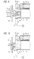
- a retainer 18 comprises a plurality of ball receiving portions 18a, connection portions 18b connecting the adjacent ball receiving portions 18a, and hook portions 18c protruded from the respective ball receiving portions 18a.
- a retainer 18 comprises a plurality of ball receiving portions 18a, connection portions 18b connecting the adjacent ball receiving portions 18a, and hook portions 18c protruded from the respective ball receiving portions 18a.
- the balls 16 are received in the ball receiving portions 18a of the retainer 18, and then the retainer 18 is rotatably attached to the shaft portion 7a1 of the flange gear 7a by elastically deforming the hook portions 18c and fitting the hook portions into a ring groove (locking portion) 7a5 formed in the shaft portion 7a1. Thereafter, the holder 15 is assembled to the shaft portion 7a1. In this way, the positions of the balls 16 in the rotational direction of the photosensitive drum 7 are regulated by the retainer 18. Further, a distance between the adjacent balls 16 is kept constant by the retainer 18.
- FIG. 7 An fourth embodiment shown in Fig. 7 is similar to the third embodiment. However, in the fourth embodiment, the retainer 18 is locked to the holder 15. In this case, the hook portions 18c are directed outwardly. The balls 16 are received in the retainer 18, the hook portions 18c are fitted in a ring groove (locking portion) 15d formed in the inner surface of the holder 15, and then the retainer and the holder are assembled to the shaft portion 7al of the flange gear 7a.
- a suction bore 17b is formed in the positioning shaft 17 and the suction bore 17b is communicated with the recesses 17a.
- a suction tool 19 is connected to the other end of the suction bore 17b remote from the recesses 17a to generate a suction force in the suction bore.
- such suction bore may be formed in the holder so that the assembling operation can easily be performed by sucking the balls 16 received in the recesses of the holder 15 by means of a suction tool connected to the suction bore.
- the balls 16 may be received in the recesses.
- cylindrical rollers 20 are used in place of the balls 16.
- recesses 7a6 which can receive the rollers 20 are formed in the outer peripheral surface of the shaft portion 7al or in the inner surface of the holder 15. The positions of the rollers 20 are regulated by the recesses 7a6, and the rotational torque of the rotary member is reduced by interposing the rollers 20 between the rotary member and the holding member.
- the balls or the rollers may be made of metal, conductive plastics or conductive elastomer
- the holder (holding member) 15 may be the same conductive material
- the holder may be contacted with an electrode.
- the balls or the rollers may be made of plastics, nylon, polyacetal or elastomer such as hard rubber.
- the balls or the rollers may be made of plastics, nylon, polyacetal or elastomer such as hard rubber.
- the rolling members may be positioned both at the driving side and at the driven side. In this case, the rotational torque can be further reduced. Further, even when the rolling members are positioned only at the driven side, the rotational torque of the rotary member can be reduced to some extent.
- the present invention is not limited to such examples, but may be applied to other rotary members in the process cartridge such as the charge roller. Furthermore, the present invention can be applied to a plurality of rotary members such as the photosensitive drum and the developing sleeve.
- the rotary member may be directly held by the cartridge frame itself.
- the process cartridge B according to the present invention can be applied to any cartridge which can form not only a mono-color image but also a multi-color image (for example, two-color image, three-color image or full-color image).
- the image bearing member is not limited to the photosensitive drum, but may be the followings.
- the photosensitive layer may be formed from photo-conductive material such as amorphous silicone, amorphous acetone, zinc oxide, titanium oxide or organic photo-conductive body. Further, the photosensitive layer may be coated on a drum-shaped rotary member, a belt-shaped rotary member or a sheet-shaped rotary member. Incidentally, in general, the drum-shaped or belt-shaped member is used, and, in case of the drum-shaped rotary member, the photosensitive layer is obtained by coating or depositing the photo-conductive material on a cylinder made of aluminum alloy and the like.
- the developing method may be, for example, the conventional two-component magnetic brush developing method, cascade developing method, touchdown developing method, cloud developing method or other developing method.
- the charge means may be, as conventionally used, designed so that the surface of the photosensitive drum is uniformly charged by providing three walls made of tangsten wires enclosed by metallic (for example, aluminium) shields and by applying the high voltage to the tangsten wires to shift the positive or negative ions (generated by the application of the high voltage) to the surface of the photosensitive drum.
- the charge means may be of blade (charge blade) type, pad type, block type, rod type or wire type, as well as the roller type.
- the cleaning means for removing the residual toner remaining on the photosensitive drum may be constituted by a blade, a fur brush or a magnetic brush.
- the process cartridge includes an image bearing member (for example, electrophotographic photosensitive body), and at least one process means.
- the process cartridge may integrally incorporate therein an image bearing member and a charge means as a unit which can be removably mounted to an image forming apparatus, or may integrally incorporate therein an image bearing member and a developing means as a unit which can be removably mounted to an image forming apparatus, or may integrally incorporate therein an image bearing member and a cleaning means as a unit which can be removably mounted to an image forming apparatus, or may integrally incorporate therein an image bearing member and two or more process means as a unit which can be removably mounted to an image forming apparatus.
- the process cartridge integrally incorporates therein an electrophotographic photosensitive body, and the charge means, developing means or cleaning means as a unit which can be removably mounted to an image forming apparatus, or integrally incorporates therein an electrophotographic photosensitive body, and at least one of the charge means, developing means and cleaning means as a unit which can be removably mounted to an image forming apparatus, or integrally incorporates therein an electrophotographic photosensitive body, and at least the developing means as a unit which can be removably mounted to an image forming apparatus.
- the present invention is not limited to this example, but may be applied to an image forming apparatus wherein a photosensitive drum and a developing sleeve are directly mounted on a body of the image forming apparatus.
- the laser beam printer was illustrated as the image forming apparatus, the present invention is not limited to the laser beam printer, but may be applied to other image forming apparatus such as an electrophotographic copying machine, a facsimile machine, a word processor and the like.
- the rolling resistance is obtained between the rotary member and the holding member by the presence of the rolling members, it is possible to reduce the torque of the process cartridge and to reduce the load fluctuation. Accordingly, the rotary member can be rotated with the smaller rotational torque, and the drive source such as the motors and the drive transmission system such as the gears can be made small-sized and inexpensive. Further, due to the reduction of the load fluctuation, it is possible to reduce the uneven rotation of the rotary member and the uneven density of the image.
- the bearing portion can be made small-sized and cheaper.
- the rolling members are made of plastics or elastomer, it is possible to absorb the shock and/or vibration during the rotation of the rotary member, thereby reducing the uneven density of the image caused by the shock and the vibration.
Claims (29)
- Cartouche de traitement (B) comportant :et pouvant être montée de façon amovible sur un corps principal (13) d'un appareil de formation d'images (A),un élément électrophotographique photosensible (7),des moyens de traitement (8, 10, 11) pour agir sur l'élément électrophotographique photosensible,un châssis de cartouche (12), etun élément rotatif (7, 10d),
caractérisée en ce qu'elle comporte en outre :des moyens de support adaptés pour supporter, avec possibilité de rotation, ledit élément rotatif sur ledit châssis de cartouche, lesdits moyens de support comprenant une pluralité d'éléments roulants (16), etun élément de retenue (18) adapté pour disposer lesdits éléments roulants de manière qu'ils puissent tourner en réglant un intervalle entre des éléments roulants adjacents, dans un sens de rotation dudit élément rotatif. - Cartouche de traitement selon la revendication 1, dans laquelle les moyens de support comprennent un élément de retenue (10g, 12a, 15, 17) adapté pour retenir l'élément rotatif, la pluralité d'éléments roulants étant assemblés entre l'élément rotatif et ledit élément de retenue indépendamment dudit élément de retenue.
- Cartouche de traitement selon l'une des revendications 1 ou 2, dans laquelle lesdits éléments roulants sont en prise avec une rainure continue formée sur une surface périphérique extérieure d'une bride d'extrémité dudit élément rotatif, dans un sens de rotation dudit élément rotatif, et avec une pluralité de renfoncements formés dans une surface intérieure d'un capuchon servant à supporter ledit élément rotatif.
- Cartouche de traitement selon l'une des revendications 1 ou 2, dans laquelle lesdits éléments roulants sont en prise avec une rainure continue formée dans une surface intérieure d'une bride d'extrémité dudit élément rotatif, dans le sens de rotation dudit élément rotatif, et avec une pluralité de renfoncements formés dans une surface périphérique extérieure d'un arbre qui fait saillie hors d'un châssis de cartouche pour supporter ledit élément rotatif.
- Cartouche de traitement selon l'une des revendications 1 ou 2, dans laquelle lesdits éléments roulants sont en prise avec une rainure continue formée dans une surface intérieure d'un capuchon pour supporter ledit élément rotatif, dans un sens de rotation dudit élément rotatif, et avec une pluralité de renfoncements formés dans une surface périphérique extérieure d'une bride d'extrémité dudit élément rotatif.
- Cartouche de traitement selon l'une des revendications 1 ou 2, dans laquelle lesdits éléments roulants sont en prise avec une rainure continue formée dans une surface extérieure d'un arbre qui fait saillie à partir d'un châssis de cartouche pour supporter ledit élément rotatif dans un sens de rotation dudit élément rotatif, et avec une pluralité de renfoncements formés dans une surface intérieure d'une bride d'extrémité dudit élément rotatif.
- Cartouche de traitement selon l'une des revendications 1 ou 2, dans laquelle lesdits éléments roulants sont en prise avec une pluralité de renfoncements formés dans une surface périphérique extérieure d'une bride d'extrémité dudit élément rotatif dans un sens de rotation dudit élément rotatif.
- Cartouche de traitement selon l'une des revendications 1 ou 2, dans laquelle lesdits éléments roulants sont en prise avec une pluralité de renfoncements formés dans une surface intérieure d'une bride d'extrémité dudit élément rotatif dans un sens de rotation dudit élément rotatif.
- Cartouche de traitement selon l'une des revendications 1 ou 2, dans laquelle lesdits éléments roulants sont en prise avec une pluralité de renfoncements formés dans une surface intérieure d'un capuchon pour supporter ledit élément rotatif dans un sens de rotation dudit élément rotatif.
- Cartouche de traitement selon l'une des revendications 1 ou 2, dans laquelle lesdits éléments roulants sont en prise avec une pluralité de renfoncements formés dans une surface périphérique extérieure d'un arbre qui fait saillie à partir d'un châssis de la cartouche pour supporter ledit élément rotatif dans un sens de rotation dudit élément rotatif.
- Cartouche de traitement selon l'une des revendications 1 ou 2, dans laquelle lesdits éléments roulants sont assemblés à un élément de retenue des éléments roulants, prévu sur une bride d'extrémité dudit élément rotatif.
- Cartouche de traitement selon l'une des revendications 1 ou 2, dans laquelle lesdits éléments roulants sont assemblés à un élément de retenue des éléments roulants, prévu sur un capuchon pour supporter ledit élément rotatif.
- Cartouche de traitement selon l'une quelconque des revendications 1 à 12, dans laquelle ledit élément rotatif est adapté pour régler les positions desdits éléments roulants dans une direction axiale et dans un sens de rotation dudit élément rotatif.
- Cartouche de traitement selon l'une quelconque des revendications 2 à 12, dans laquelle ledit élément de retenue est adapté pour régler les positions desdits éléments roulants dans une direction axiale et dans un sens de rotation dudit élément rotatif.
- Cartouche de traitement selon l'une quelconque des revendications 2 à 12, dans laquelle ledit élément rotatif et ledit élément de retenue sont adaptés pour régler les positions desdits éléments roulants dans une direction axiale dudit élément rotatif, et ledit élément rotatif est adapté pour régler les positions desdits éléments roulants dans un sens de rotation dudit élément rotatif.
- Cartouche de traitement selon l'une quelconque des revendications 2 à 12, dans laquelle ledit élément rotatif et ledit élément de retenue sont adaptés pour régler les positions desdits éléments roulants dans une direction axiale dudit élément rotatif, et ledit élément roulant est adapté pour régler les positions desdits éléments roulants dans un sens de rotation dudit élément rotatif.
- Cartouche de traitement selon l'une quelconque des revendications 1 à 16, comprenant en outre un élément de régulation pour régler les positions desdits éléments roulants dans un sens de rotation dudit élément rotatif de telle sorte que les positions desdits éléments roulants dans une direction axiale dudit élément rotatif sont réglées par venue en prise dudit élément de régulation avec ledit élément rotatif.
- Cartouche de traitement selon l'une quelconque des revendications 2 à 16, comprenant en outre un élément de régulation pour régler les positions desdits éléments roulants dans un sens de rotation dudit élément rotatif de telle sorte que les positions desdits éléments roulants dans une direction axiale dudit élément rotatif sont réglées par venue en prise dudit élément de régulation avec ledit élément de retenue.
- Cartouche de traitement selon l'une quelconque des revendications 1 à 18, dans laquelle lesdits éléments roulants sont formés d'une matière plastique ou d'un élastomère.
- Cartouche de traitement selon l'une quelconque des revendications 1 à 19, dans laquelle lesdits éléments roulants sont formés d'un matériau conducteur de sorte que ledit élément rotatif est connecté électriquement audit élément de retenue par l'intermédiaire desdits éléments roulants.
- Cartouche de traitement selon l'une quelconque des revendications 1 à 20, dans laquelle lesdits éléments roulants sont positionnés uniquement sur un côté d'entraínement dudit élément rotatif dans une extrémité axiale dudit élément rotatif.
- Cartouche de traitement selon l'une quelconque des revendications 1 à 21, dans laquelle lesdits éléments roulants sont des billes.
- Cartouche de traitement selon l'une quelconque des revendications 1 à 21, dans laquelle lesdits éléments roulants sont des rouleaux.
- Cartouche de traitement selon l'une quelconque des revendications 1 à 23, dans laquelle ledit élément rotatif comprend un tambour photosensible en tant qu'élément de support d'image.
- Cartouche de traitement selon l'une quelconque des revendications 1 à 24, dans laquelle ledit élément rotatif comporte un manchon de développement en tant qu'élément de support de l'agent de développement.
- Cartouche de traitement selon l'une quelconque des revendications 1 à 25, dans laquelle ledit élément rotatif comprend un rouleau de charge en tant que moyen de charge.
- Cartouche de traitement selon l'une quelconque des revendications 1 à 26, qui incorpore de manière intégrée en elle un corps électrophotographique photosensible en tant qu'élément de support d'image et des moyens de charge, des moyens de développement ou des moyens de nettoyage en tant que moyens de traitement, sous la forme d'une unité qui peut être montée de façon amovible sur un appareil de formation d'images.
- Cartouche de traitement selon l'une quelconque des revendications 1 à 27, qui incorpore en elle, de façon intégrée, un corps électrophotographique photosensible en tant qu'élément de support d'image, et au moins l'un de moyens formés de moyens de charge, de moyens de développement et de moyens de nettoyage en tant que moyens de traitement, sous la forme d'une unité qui peut être montée de façon amovible sur l'appareil de formation d'images.
- Cartouche de traitement selon l'une quelconque des revendications 1 à 28, qui incorpore en elle, de façon intégrée, un corps électrophotographique photosensible en tant qu'élément de support d'image, et au moins des moyens de développement en tant que moyens de traitement sous la forme d'une unité qui peut être montée de façon amovible dans un appareil de formation d'images.
Applications Claiming Priority (6)
| Application Number | Priority Date | Filing Date | Title |
|---|---|---|---|
| JP118518/93 | 1993-05-20 | ||
| JP11851893 | 1993-05-20 | ||
| JP174118/93 | 1993-07-14 | ||
| JP17411893 | 1993-07-14 | ||
| JP299914/93 | 1993-11-30 | ||
| JP29991493A JP3297516B2 (ja) | 1993-07-14 | 1993-11-30 | 転動体の取り付け方法 |
Publications (3)
| Publication Number | Publication Date |
|---|---|
| EP0625729A2 EP0625729A2 (fr) | 1994-11-23 |
| EP0625729A3 EP0625729A3 (fr) | 1995-08-09 |
| EP0625729B1 true EP0625729B1 (fr) | 1998-11-04 |
Family
ID=27313603
Family Applications (1)
| Application Number | Title | Priority Date | Filing Date |
|---|---|---|---|
| EP93403205A Expired - Lifetime EP0625729B1 (fr) | 1993-05-20 | 1993-12-29 | Une cartouche de traitement |
Country Status (3)
| Country | Link |
|---|---|
| US (2) | US5463446A (fr) |
| EP (1) | EP0625729B1 (fr) |
| DE (1) | DE69321944T2 (fr) |
Families Citing this family (88)
| Publication number | Priority date | Publication date | Assignee | Title |
|---|---|---|---|---|
| JP3285414B2 (ja) * | 1993-04-28 | 2002-05-27 | キヤノン株式会社 | プロセスカートリッジ及び画像形成装置 |
| JP3869868B2 (ja) * | 1994-04-27 | 2007-01-17 | キヤノン株式会社 | プロセスカートリッジ及び画像形成装置 |
| AU3426895A (en) * | 1994-10-17 | 1996-05-02 | Canon Kabushiki Kaisha | Toner container, toner container assembling method, process cartridge, and electrophotographic image forming apparatus |
| JP3839932B2 (ja) | 1996-09-26 | 2006-11-01 | キヤノン株式会社 | プロセスカートリッジ及び電子写真画像形成装置及び電子写真感光体ドラム及びカップリング |
| JP2875203B2 (ja) * | 1995-03-27 | 1999-03-31 | キヤノン株式会社 | 電子写真画像形成装置、プロセスカートリッジ、駆動力伝達部品、及び、電子写真感光体ドラム |
| JP3315560B2 (ja) * | 1995-06-13 | 2002-08-19 | キヤノン株式会社 | プロセスカートリッジ及び電子写真画像形成装置及び電子写真感光体ドラムの取り付け方法 |
| JP3372719B2 (ja) * | 1995-07-11 | 2003-02-04 | キヤノン株式会社 | プロセスカートリッジ及び画像形成装置 |
| US5768658A (en) * | 1995-07-21 | 1998-06-16 | Canon Kabushiki Kaisha | Electrode member, developing apparatus, process cartridge and image forming apparatus |
| JP3492129B2 (ja) * | 1996-01-09 | 2004-02-03 | キヤノン株式会社 | プロセスカートリッジ、現像装置、及び、電子写真画像形成装置 |
| US6240266B1 (en) | 1996-03-21 | 2001-05-29 | Canon Kabushiki Kaisha | Process cartridge and drum mount for photosensitive drum |
| US6226478B1 (en) | 1996-03-21 | 2001-05-01 | Canon Kabushiki Kaisha | Process cartridge having drive mount for photosensitive drum |
| JP3337916B2 (ja) | 1996-07-04 | 2002-10-28 | キヤノン株式会社 | プロセスカートリッジ及び電子写真画像形成装置及び軸受ガイド部品 |
| JP3363751B2 (ja) * | 1996-08-29 | 2003-01-08 | キヤノン株式会社 | プロセスカートリッジ及び電子写真画像形成装置 |
| JP4026895B2 (ja) | 1996-09-26 | 2007-12-26 | キヤノン株式会社 | 電子写真画像形成装置及びプロセスカートリッジ |
| CN1117296C (zh) | 1996-09-26 | 2003-08-06 | 佳能株式会社 | 处理盒,电子照相成象装置驱动力传动部件以及电子照相感光鼓 |
| JP3969804B2 (ja) | 1996-09-26 | 2007-09-05 | キヤノン株式会社 | 電子写真画像形成装置 |
| JP3363727B2 (ja) * | 1996-12-12 | 2003-01-08 | キヤノン株式会社 | プロセスカートリッジ及び電子写真画像形成装置及びプロセスカートリッジの組立方法及び廃トナー容器の組立方法 |
| KR100242117B1 (ko) * | 1997-04-07 | 2000-02-01 | 윤종용 | 전자사진 프로세서의 화상형성장치 |
| JP3332813B2 (ja) * | 1997-08-01 | 2002-10-07 | キヤノン株式会社 | プロセスカートリッジ及び電子写真画像形成装置 |
| JP3466888B2 (ja) * | 1997-10-01 | 2003-11-17 | キヤノン株式会社 | プロセスカートリッジ及び電子写真画像形成装置 |
| JP3472108B2 (ja) * | 1997-10-01 | 2003-12-02 | キヤノン株式会社 | プロセスカートリッジ及び電子写真画像形成装置 |
| JP3420486B2 (ja) * | 1997-11-07 | 2003-06-23 | キヤノン株式会社 | プロセスカートリッジ及び電子写真画像形成装置 |
| US5822654A (en) * | 1997-11-14 | 1998-10-13 | Xerox Corporation | Development bias connector with integral bearing support |
| JPH11249495A (ja) * | 1998-03-03 | 1999-09-17 | Canon Inc | アース部材、円筒部材、プロセスカートリッジ、電子写真画像形成装置 |
| JPH11249494A (ja) | 1998-03-03 | 1999-09-17 | Canon Inc | ドラムフランジ、円筒部材、プロセスカートリッジ、電子写真画像形成装置 |
| JP2000010454A (ja) * | 1998-06-19 | 2000-01-14 | Ricoh Co Ltd | 画像形成装置 |
| JP2000066498A (ja) | 1998-08-21 | 2000-03-03 | Canon Inc | 電子写真画像形成装置及びプロセスカートリッジ |
| JP3437460B2 (ja) | 1998-08-31 | 2003-08-18 | キヤノン株式会社 | トナー容器 |
| JP2000075733A (ja) * | 1998-08-31 | 2000-03-14 | Canon Inc | 電子写真感光体ドラム取り付け方法、及び、電子写真感光体ドラム交換方法、及び、プロセスカートリッジ |
| JP3673658B2 (ja) | 1998-10-28 | 2005-07-20 | キヤノン株式会社 | プロセスカートリッジ及び電子写真画像形成装置 |
| JP3684092B2 (ja) | 1998-10-26 | 2005-08-17 | キヤノン株式会社 | 電子写真画像形成装置 |
| JP3697090B2 (ja) | 1998-10-26 | 2005-09-21 | キヤノン株式会社 | 電子写真画像形成装置 |
| DE60000216T2 (de) | 1999-02-26 | 2002-11-28 | Brother Ind Ltd | Kartusche für ein photosensitives Bestandteil |
| JP3347686B2 (ja) | 1999-04-02 | 2002-11-20 | キヤノン株式会社 | 電子写真画像形成装置及びプロセスカートリッジ押込み機構 |
| JP3748506B2 (ja) | 1999-05-20 | 2006-02-22 | キヤノン株式会社 | プロセスカートリッジ及びプロセスカートリッジの組立方法 |
| JP3320399B2 (ja) | 1999-05-20 | 2002-09-03 | キヤノン株式会社 | プロセスカートリッジ及びプロセスカートリッジの組み立て方法及び電子写真画像形成装置 |
| JP3320398B2 (ja) | 1999-05-20 | 2002-09-03 | キヤノン株式会社 | プロセスカートリッジおよび電子写真画像形成装置 |
| JP3363873B2 (ja) | 1999-07-13 | 2003-01-08 | キヤノン株式会社 | 現像剤量逐次表示方法及び電子写真画像形成装置 |
| JP2001051490A (ja) | 1999-08-06 | 2001-02-23 | Canon Inc | 現像装置、プロセスカートリッジ及び電子写真画像形成装置 |
| JP3943772B2 (ja) | 1999-08-06 | 2007-07-11 | キヤノン株式会社 | 現像装置、プロセスカートリッジ及び電子写真画像形成装置 |
| JP2001092335A (ja) | 1999-09-17 | 2001-04-06 | Canon Inc | プロセスカートリッジ、電子写真画像形成装置及び現像剤量検出部材 |
| JP3787487B2 (ja) | 1999-10-08 | 2006-06-21 | キヤノン株式会社 | プロセスカートリッジ装着機構、電子写真画像形成装置、及びプロセスカートリッジ |
| JP2001255786A (ja) | 2000-01-07 | 2001-09-21 | Canon Inc | 電子写真画像形成装置 |
| JP3745231B2 (ja) | 2000-01-13 | 2006-02-15 | キヤノン株式会社 | プロセスカートリッジ及び電子写真画像形成装置 |
| US6549736B2 (en) | 2000-01-19 | 2003-04-15 | Canon Kabushiki Kaisha | Process cartridge, engaging member therefor and method for mounting developing roller and magnet |
| JP2001290355A (ja) | 2000-04-06 | 2001-10-19 | Canon Inc | 現像装置、プロセスカートリッジ及び電子写真画像形成装置 |
| US6259873B1 (en) * | 2000-05-19 | 2001-07-10 | Nexpress Solutions Llc | Cantilever drum mount for document printer/copier |
| US6603939B1 (en) | 2000-06-09 | 2003-08-05 | Canon Kabushiki Kaisha | Developing apparatus, process cartridge, connecting method between developing frame and developer frame, and flexible seal |
| US6697578B2 (en) | 2000-08-25 | 2004-02-24 | Canon Kabushiki Kaisha | Memory member, unit, process cartridge and electrophotographic image forming apparatus |
| JP3658315B2 (ja) | 2000-12-19 | 2005-06-08 | キヤノン株式会社 | プロセスカートリッジ及び電子写真画像形成装置 |
| JP2002196647A (ja) | 2000-12-22 | 2002-07-12 | Canon Inc | プロセスカートリッジ及び画像形成装置 |
| JP4677093B2 (ja) | 2000-12-25 | 2011-04-27 | キヤノン株式会社 | プロセスカートリッジ |
| JP2002258720A (ja) | 2001-03-05 | 2002-09-11 | Canon Inc | 電子写真画像形成装置及びプロセスカートリッジ |
| JP3697168B2 (ja) | 2001-03-09 | 2005-09-21 | キヤノン株式会社 | プロセスカートリッジおよび電子写真画像形成装置 |
| JP4819232B2 (ja) | 2001-03-09 | 2011-11-24 | キヤノン株式会社 | プロセスカートリッジ、及びこれを備えた画像形成装置 |
| JP3625431B2 (ja) | 2001-03-16 | 2005-03-02 | キヤノン株式会社 | プロセスカートリッジ着脱機構、プロセスカートリッジ及び電子写真画像形成装置 |
| JP2002278415A (ja) | 2001-03-16 | 2002-09-27 | Canon Inc | プロセスカートリッジ及び電子写真画像形成装置 |
| JP3631155B2 (ja) | 2001-03-16 | 2005-03-23 | キヤノン株式会社 | プロセスカートリッジ着脱機構 |
| JP3564080B2 (ja) | 2001-04-27 | 2004-09-08 | キヤノン株式会社 | プロセスカートリッジの再生産方法 |
| JP3840063B2 (ja) | 2001-04-27 | 2006-11-01 | キヤノン株式会社 | プロセスカートリッジ |
| JP3542569B2 (ja) | 2001-04-27 | 2004-07-14 | キヤノン株式会社 | プロセスカートリッジの再生産方法 |
| US6540407B2 (en) | 2001-06-12 | 2003-04-01 | Electric Boat Corporation | Rolling element bearing arrangement |
| JP2004028299A (ja) * | 2002-06-28 | 2004-01-29 | Ricoh Co Ltd | 回転体支持構造および画像形成装置 |
| US6835012B1 (en) * | 2002-09-04 | 2004-12-28 | International Imaging Materials Inc. | Ribbon cassette |
| JP3548564B2 (ja) * | 2002-11-08 | 2004-07-28 | キヤノン株式会社 | 現像ローラー組立方法 |
| JP4110128B2 (ja) * | 2004-04-26 | 2008-07-02 | キヤノン株式会社 | プロセスカートリッジ、電子写真画像形成装置及び軸受部材 |
| US20060008289A1 (en) * | 2004-07-06 | 2006-01-12 | Canon Kabushiki Kaisha | Electrophotographic image forming apparatus and process cartridge |
| JP4617122B2 (ja) | 2004-09-08 | 2011-01-19 | キヤノン株式会社 | 現像剤搬送部材、現像装置、および、プロセスカートリッジ |
| JP3950883B2 (ja) * | 2004-10-06 | 2007-08-01 | キヤノン株式会社 | 電子写真画像形成装置 |
| JP4498407B2 (ja) | 2006-12-22 | 2010-07-07 | キヤノン株式会社 | プロセスカートリッジ、電子写真画像形成装置、及び、電子写真感光体ドラムユニット |
| JP4948382B2 (ja) * | 2006-12-22 | 2012-06-06 | キヤノン株式会社 | 感光ドラム取り付け用カップリング部材 |
| JP5311854B2 (ja) | 2007-03-23 | 2013-10-09 | キヤノン株式会社 | 電子写真画像形成装置、現像装置、及び、カップリング部材 |
| US7711287B2 (en) * | 2007-05-15 | 2010-05-04 | Canon Kabushiki Kaisha | Cartridge and electrophotographic image forming apparatus |
| EP2120315B1 (fr) * | 2008-05-15 | 2014-02-26 | Siemens Aktiengesellschaft | Dispositif d'entraînement |
| JP5127584B2 (ja) | 2008-06-20 | 2013-01-23 | キヤノン株式会社 | ドラムユニット、及び、電子写真画像形成装置 |
| JP5288900B2 (ja) | 2008-06-20 | 2013-09-11 | キヤノン株式会社 | プロセスカートリッジ及び電子写真画像形成装置 |
| JP5306050B2 (ja) * | 2008-06-20 | 2013-10-02 | キヤノン株式会社 | カートリッジ、カップリング部材の取り付け方法、及び、カップリング部材の取り外し方法 |
| EP2333620A1 (fr) | 2008-09-01 | 2011-06-15 | Canon Kabushiki Kaisha | Cartouche de développement, cartouche de procédé et appareil de formation d'image électrophotographique |
| JP5147607B2 (ja) * | 2008-09-01 | 2013-02-20 | キヤノン株式会社 | 画像形成装置 |
| JP5335329B2 (ja) * | 2008-09-01 | 2013-11-06 | キヤノン株式会社 | 画像形成装置 |
| JP4663801B2 (ja) * | 2008-09-01 | 2011-04-06 | キヤノン株式会社 | プロセスカートリッジ及び画像形成装置 |
| US8029284B2 (en) * | 2008-09-29 | 2011-10-04 | Maxillent Ltd. | Implants, tools, and methods for sinus lift and lateral ridge augmentation |
| JP5751779B2 (ja) * | 2009-10-30 | 2015-07-22 | キヤノン株式会社 | 現像装置、現像カートリッジ、プロセスカートリッジ、及び、画像形成装置 |
| JP5693213B2 (ja) * | 2010-01-13 | 2015-04-01 | キヤノン株式会社 | ドラム支持機構、プロセスカートリッジ及び電子写真画像形成装置 |
| CN106773583B (zh) | 2011-11-26 | 2020-08-11 | 江西亿铂电子科技有限公司 | 一种控制机构及包含该控制机构的处理盒 |
| US9766894B2 (en) * | 2014-02-06 | 2017-09-19 | Optimum Semiconductor Technologies, Inc. | Method and apparatus for enabling a processor to generate pipeline control signals |
| JP6631455B2 (ja) * | 2016-09-27 | 2020-01-15 | 京セラドキュメントソリューションズ株式会社 | 抜け止め部材およびそれを備えた画像形成装置 |
| CN111812953A (zh) * | 2019-08-05 | 2020-10-23 | 卢敬坤 | 一种旋转力接收件 |
Family Cites Families (9)
| Publication number | Priority date | Publication date | Assignee | Title |
|---|---|---|---|---|
| DE2021409C3 (de) * | 1970-04-30 | 1980-04-10 | Agfa-Gevaert Ag, 5090 Leverkusen | Elektrostatisches Kopiergerät mit einer auswechselbaren Kopiertrommel |
| JPS5549745B2 (fr) * | 1973-10-31 | 1980-12-13 | ||
| US3985432A (en) * | 1974-07-31 | 1976-10-12 | Addressograph Multigraph Corporation | Modulator screen drum assembly |
| JPS58181058A (ja) * | 1982-04-19 | 1983-10-22 | Mita Ind Co Ltd | 静電複写機 |
| JPS59152458A (ja) * | 1983-02-21 | 1984-08-31 | Mita Ind Co Ltd | シエル型静電複写機 |
| JPH02304459A (ja) * | 1989-05-19 | 1990-12-18 | Hitachi Ltd | 電子写真プリンタのドラム駆動装置 |
| JPH03101751A (ja) * | 1989-09-16 | 1991-04-26 | Canon Inc | プロセスカートリッジ |
| JP2594653B2 (ja) * | 1989-10-31 | 1997-03-26 | 三田工業株式会社 | 駆動連結装置 |
| US5283616A (en) * | 1991-12-19 | 1994-02-01 | Canon Kabushiki Kaisha | Developing device having bearing for supporting a developing roller |
-
1993
- 1993-12-29 EP EP93403205A patent/EP0625729B1/fr not_active Expired - Lifetime
- 1993-12-29 DE DE69321944T patent/DE69321944T2/de not_active Expired - Fee Related
- 1993-12-29 US US08/174,809 patent/US5463446A/en not_active Expired - Fee Related
-
1995
- 1995-07-13 US US08/501,929 patent/US5640650A/en not_active Expired - Fee Related
Also Published As
| Publication number | Publication date |
|---|---|
| EP0625729A2 (fr) | 1994-11-23 |
| DE69321944D1 (de) | 1998-12-10 |
| EP0625729A3 (fr) | 1995-08-09 |
| US5463446A (en) | 1995-10-31 |
| US5640650A (en) | 1997-06-17 |
| DE69321944T2 (de) | 1999-04-29 |
Similar Documents
| Publication | Publication Date | Title |
|---|---|---|
| EP0625729B1 (fr) | Une cartouche de traitement | |
| EP0754984B1 (fr) | Cartouche, sous-cartouche, appareil de développement, et appareil de formation d'images | |
| JP4110128B2 (ja) | プロセスカートリッジ、電子写真画像形成装置及び軸受部材 | |
| US5963759A (en) | Process cartridge and image forming apparatus to which process cartridge can detachably be mounted | |
| US5223893A (en) | Process cartridge detachably mountable to image forming apparatus | |
| US5537187A (en) | Process cartridge having a frame connecting member with a guide portion, and image forming apparatus using same | |
| US7068965B2 (en) | Developing cartridge, side cover mounting method and electrophotographic image forming apparatus | |
| JP4164293B2 (ja) | 現像装置及びプロセスカートリッジ及び画像形成装置 | |
| US7440715B2 (en) | Electrophotographic photosensitive drum, process cartridge, and electrophotographic image forming apparatus | |
| US6317572B1 (en) | Electrophotographic image forming apparatus and process cartridge detachably mountable thereto comprising a positioning portion for engagement with a positioning member of a main assembly of the image forming apparatus | |
| US8687994B2 (en) | Cartridge with roller shaft having an exposed electroconductive portion | |
| EP1016943A2 (fr) | Unité de traitement et appareil électrophotographique de formation d'images | |
| US8218997B2 (en) | Cleaning member, charging device, process cartridge, and image forming apparatus | |
| EP1209538B1 (fr) | Elément de contact électrique et dispositif de développement, unité de traitement, et appareil électrophotographique de formation d'images utilisant l'élément de contact électrique | |
| EP1316852B1 (fr) | Dispositif de développement, unité de traitement et appareil pour la formation d'images utilisant une pression entre le rouleau de développement et le tambour photosensible indépendante de la quantité résiduelle de révélateur dans le récipient de toner | |
| US6181897B1 (en) | Developing apparatus | |
| EP1054300B1 (fr) | Dispositif de développement avec une connexion d'alimentation pour appliquer une tension de polarisation | |
| US6411791B2 (en) | Developing apparatus including a developer charging member shaft and a holding member including a shaft guide groove | |
| JP3297516B2 (ja) | 転動体の取り付け方法 | |
| JP2005099231A (ja) | プロセスカートリッジ及び電子写真画像形成装置 | |
| JP4856891B2 (ja) | 現像ローラ及び現像装置並びにプロセスカートリッジ | |
| JPH0943967A (ja) | 現像装置、プロセスカートリッジ、及び画像形成装置 | |
| CN1095492A (zh) | 滚动部件、旋转部件、制版暗盒和成象装置的装配方法 | |
| JP2002162829A (ja) | 現像装置、現像カートリッジ、プロセスカートリッジ、及び電子写真画像形成装置 |
Legal Events
| Date | Code | Title | Description |
|---|---|---|---|
| PUAI | Public reference made under article 153(3) epc to a published international application that has entered the european phase |
Free format text: ORIGINAL CODE: 0009012 |
|
| AK | Designated contracting states |
Kind code of ref document: A2 Designated state(s): CH DE FR GB IT LI |
|
| PUAL | Search report despatched |
Free format text: ORIGINAL CODE: 0009013 |
|
| AK | Designated contracting states |
Kind code of ref document: A3 Designated state(s): CH DE ES FR GB IT LI NL |
|
| 17P | Request for examination filed |
Effective date: 19960120 |
|
| 17Q | First examination report despatched |
Effective date: 19961223 |
|
| GRAG | Despatch of communication of intention to grant |
Free format text: ORIGINAL CODE: EPIDOS AGRA |
|
| GRAG | Despatch of communication of intention to grant |
Free format text: ORIGINAL CODE: EPIDOS AGRA |
|
| GRAH | Despatch of communication of intention to grant a patent |
Free format text: ORIGINAL CODE: EPIDOS IGRA |
|
| GRAG | Despatch of communication of intention to grant |
Free format text: ORIGINAL CODE: EPIDOS AGRA |
|
| GRAH | Despatch of communication of intention to grant a patent |
Free format text: ORIGINAL CODE: EPIDOS IGRA |
|
| GRAG | Despatch of communication of intention to grant |
Free format text: ORIGINAL CODE: EPIDOS AGRA |
|
| GRAH | Despatch of communication of intention to grant a patent |
Free format text: ORIGINAL CODE: EPIDOS IGRA |
|
| RBV | Designated contracting states (corrected) |
Designated state(s): CH DE FR GB IT LI |
|
| GRAH | Despatch of communication of intention to grant a patent |
Free format text: ORIGINAL CODE: EPIDOS IGRA |
|
| GRAA | (expected) grant |
Free format text: ORIGINAL CODE: 0009210 |
|
| AK | Designated contracting states |
Kind code of ref document: B1 Designated state(s): CH DE FR GB IT LI |
|
| REG | Reference to a national code |
Ref country code: CH Ref legal event code: EP |
|
| REG | Reference to a national code |
Ref country code: CH Ref legal event code: NV Representative=s name: BOVARD AG PATENTANWAELTE |
|
| REF | Corresponds to: |
Ref document number: 69321944 Country of ref document: DE Date of ref document: 19981210 |
|
| ET | Fr: translation filed | ||
| PLBE | No opposition filed within time limit |
Free format text: ORIGINAL CODE: 0009261 |
|
| STAA | Information on the status of an ep patent application or granted ep patent |
Free format text: STATUS: NO OPPOSITION FILED WITHIN TIME LIMIT |
|
| 26N | No opposition filed | ||
| REG | Reference to a national code |
Ref country code: GB Ref legal event code: IF02 |
|
| PGFP | Annual fee paid to national office [announced via postgrant information from national office to epo] |
Ref country code: FR Payment date: 20031210 Year of fee payment: 11 |
|
| PGFP | Annual fee paid to national office [announced via postgrant information from national office to epo] |
Ref country code: GB Payment date: 20031224 Year of fee payment: 11 |
|
| PGFP | Annual fee paid to national office [announced via postgrant information from national office to epo] |
Ref country code: CH Payment date: 20040105 Year of fee payment: 11 |
|
| PGFP | Annual fee paid to national office [announced via postgrant information from national office to epo] |
Ref country code: DE Payment date: 20040108 Year of fee payment: 11 |
|
| PG25 | Lapsed in a contracting state [announced via postgrant information from national office to epo] |
Ref country code: GB Free format text: LAPSE BECAUSE OF NON-PAYMENT OF DUE FEES Effective date: 20041229 |
|
| PG25 | Lapsed in a contracting state [announced via postgrant information from national office to epo] |
Ref country code: LI Free format text: LAPSE BECAUSE OF NON-PAYMENT OF DUE FEES Effective date: 20041231 Ref country code: CH Free format text: LAPSE BECAUSE OF NON-PAYMENT OF DUE FEES Effective date: 20041231 |
|
| PG25 | Lapsed in a contracting state [announced via postgrant information from national office to epo] |
Ref country code: DE Free format text: LAPSE BECAUSE OF NON-PAYMENT OF DUE FEES Effective date: 20050701 |
|
| REG | Reference to a national code |
Ref country code: CH Ref legal event code: PL |
|
| GBPC | Gb: european patent ceased through non-payment of renewal fee |
Effective date: 20041229 |
|
| PG25 | Lapsed in a contracting state [announced via postgrant information from national office to epo] |
Ref country code: FR Free format text: LAPSE BECAUSE OF NON-PAYMENT OF DUE FEES Effective date: 20050831 |
|
| REG | Reference to a national code |
Ref country code: FR Ref legal event code: ST |
|
| PG25 | Lapsed in a contracting state [announced via postgrant information from national office to epo] |
Ref country code: IT Free format text: LAPSE BECAUSE OF NON-PAYMENT OF DUE FEES;WARNING: LAPSES OF ITALIAN PATENTS WITH EFFECTIVE DATE BEFORE 2007 MAY HAVE OCCURRED AT ANY TIME BEFORE 2007. THE CORRECT EFFECTIVE DATE MAY BE DIFFERENT FROM THE ONE RECORDED. Effective date: 20051229 |