EP1016943A2 - Unité de traitement et appareil électrophotographique de formation d'images - Google Patents
Unité de traitement et appareil électrophotographique de formation d'images Download PDFInfo
- Publication number
- EP1016943A2 EP1016943A2 EP99310457A EP99310457A EP1016943A2 EP 1016943 A2 EP1016943 A2 EP 1016943A2 EP 99310457 A EP99310457 A EP 99310457A EP 99310457 A EP99310457 A EP 99310457A EP 1016943 A2 EP1016943 A2 EP 1016943A2
- Authority
- EP
- European Patent Office
- Prior art keywords
- process cartridge
- charging
- photosensitive drum
- electrophotographic photosensitive
- developing
- Prior art date
- Legal status (The legal status is an assumption and is not a legal conclusion. Google has not performed a legal analysis and makes no representation as to the accuracy of the status listed.)
- Withdrawn
Links
Images


Classifications
-
- G—PHYSICS
- G03—PHOTOGRAPHY; CINEMATOGRAPHY; ANALOGOUS TECHNIQUES USING WAVES OTHER THAN OPTICAL WAVES; ELECTROGRAPHY; HOLOGRAPHY
- G03G—ELECTROGRAPHY; ELECTROPHOTOGRAPHY; MAGNETOGRAPHY
- G03G15/00—Apparatus for electrographic processes using a charge pattern
-
- G—PHYSICS
- G03—PHOTOGRAPHY; CINEMATOGRAPHY; ANALOGOUS TECHNIQUES USING WAVES OTHER THAN OPTICAL WAVES; ELECTROGRAPHY; HOLOGRAPHY
- G03G—ELECTROGRAPHY; ELECTROPHOTOGRAPHY; MAGNETOGRAPHY
- G03G21/00—Arrangements not provided for by groups G03G13/00 - G03G19/00, e.g. cleaning, elimination of residual charge
- G03G21/16—Mechanical means for facilitating the maintenance of the apparatus, e.g. modular arrangements
- G03G21/18—Mechanical means for facilitating the maintenance of the apparatus, e.g. modular arrangements using a processing cartridge, whereby the process cartridge comprises at least two image processing means in a single unit
- G03G21/1803—Arrangements or disposition of the complete process cartridge or parts thereof
- G03G21/1817—Arrangements or disposition of the complete process cartridge or parts thereof having a submodular arrangement
- G03G21/1821—Arrangements or disposition of the complete process cartridge or parts thereof having a submodular arrangement means for connecting the different parts of the process cartridge, e.g. attachment, positioning of parts with each other, pressure/distance regulation
-
- G—PHYSICS
- G03—PHOTOGRAPHY; CINEMATOGRAPHY; ANALOGOUS TECHNIQUES USING WAVES OTHER THAN OPTICAL WAVES; ELECTROGRAPHY; HOLOGRAPHY
- G03G—ELECTROGRAPHY; ELECTROPHOTOGRAPHY; MAGNETOGRAPHY
- G03G2215/00—Apparatus for electrophotographic processes
- G03G2215/02—Arrangements for laying down a uniform charge
- G03G2215/021—Arrangements for laying down a uniform charge by contact, friction or induction
-
- G—PHYSICS
- G03—PHOTOGRAPHY; CINEMATOGRAPHY; ANALOGOUS TECHNIQUES USING WAVES OTHER THAN OPTICAL WAVES; ELECTROGRAPHY; HOLOGRAPHY
- G03G—ELECTROGRAPHY; ELECTROPHOTOGRAPHY; MAGNETOGRAPHY
- G03G2221/00—Processes not provided for by group G03G2215/00, e.g. cleaning or residual charge elimination
- G03G2221/16—Mechanical means for facilitating the maintenance of the apparatus, e.g. modular arrangements and complete machine concepts
- G03G2221/1606—Mechanical means for facilitating the maintenance of the apparatus, e.g. modular arrangements and complete machine concepts for the photosensitive element
- G03G2221/1609—Mechanical means for facilitating the maintenance of the apparatus, e.g. modular arrangements and complete machine concepts for the photosensitive element protective arrangements for preventing damage
Definitions
- the present invention relates to a process cartridge removably installable in the main assembly of an electrophotographic image forming apparatus, and an electrophotographic image forming apparatus.
- an electrophotographic image forming apparatus means an image forming apparatus which employs an electrophotographic system to form images or recording medium.
- it includes electrophotographic copying machines, electrophotographic printers (laser beam printers, LED printers, and the like), facsimile machines, word processors, and the like.
- a process cartridge means a cartridge which integrally comprises a charging means, a developing means or a cleaning means, and an electrophotographic photosensitive drum, and which is rendered removably installable in the main assembly of an electrophotographic image forming apparatus. It also means a cartridge comprising at least a charging means, a developing means, or cleaning means, in addition to an electrophotographic photosensitive drum, and is rendered removably installable in the main assembly of an electrophotographic image forming apparatus. It also means a cartridge comprising at least a developing means, and an electrophotographic photosensitive drum, and which is rendered removably installable in the main assembly of an electrophotographic image forming apparatus.
- an image forming apparatus which employed an electrophotographic image formation process employed a process cartridge system, according to which an electrophotographic photosensitive member, and one or a plurality of processing means which works on the electrophotographic photosensitive member, are integrally assembled in the form of a cartridge removably installable in the main assembly of an image forming apparatus.
- the maintenance for an image forming apparatus can be performed by a user him/herself; the user does not need to rely on a service person for the maintenance. Therefore, the employment of a process cartridge system drastically improved the operational efficiency of an image forming apparatus. As a result, a process cartridge system has been widely used in the field of the image forming apparatus.
- the process cartridge used with the above described process cartridge system is in the form of a cartridge which comprises: a development unit integrally comprising a development unit frame in which a development roller and a development blade are disposed, and a toner chamber frame which stores toner as developer; and a cleaning unit frame which supports a photosensitive drum, houses a cleaning blade and the like, and is pivotally connected to the development unit.
- the present invention is a result of the further development of the aforementioned prior technology.
- the primary object of the present invention is to provide a process cartridge capable of more reliably supporting an electrophotographic photosensitive drum, and an electrophotographic image forming apparatus compatible with such a process cartridge.
- Another object of the present invention is to provide a process cartridge superior in terms of assembly, and an electrophotographic image forming apparatus compatible with such a process cartridge.
- Another object of the present invention is to provide a process cartridge not only capable of reliably supporting an electrophotographic photosensitive drum, but also superior in terms of assembly, and an electrophotographic image forming apparatus compatible with such a process cartridge.
- a process cartridge comprises: (a) a development unit which supports an electrophotographic photosensitive drum, and a development member for developing an electrostatic latent image formed on the electrophotographic photosensitive drum, with the use of developer; and (b) a charge unit which supports a charging member for charging the electrophotographic photosensitive drum, and is pivotable about a pivot center in the first direction, that is, the direction to cause the charging member to move toward the electrophotographic photosensitive drum, and also in the second direction, that is, the direction to cause the charging member to move away from the electrophotographic photosensitive drum, and an electrophotographic image forming apparatus in which such a process cartridge is removably installable.
- Figure 1 is a vertical section of an electrophotographic image forming apparatus.
- Figure 2 is a vertical sectional view of a process cartridge.
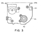
- Figure 3 is a front view of a process cartridge.
- Figure 4 is a right side view of the process cartridge.
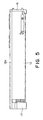
- Figure 5 is a left side view of the process cartridge.
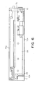
- Figure 6 is a top view of the process cartridge.
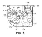
- Figure 7 is a rear view of the process cartridge.
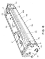
- Figure 8 is a perspective view of the process cartridge, as seen from the right front.
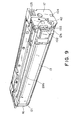
- Figure 9 is a perspective view of the process cartridge, as seen from the left rear.
- Figure 10 is a perspective view of the process cartridge placed upside down, as seen from the left rear.
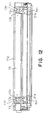
- Figure 11 is a front view of a charging unit.
- Figure 12 is a front view of the charging unit illustrated in Figure 11, with its blade removed.
- Figure 13 is a rear view of a development unit, with its rear cover removed.
- Figure 14 is a front view of the development unit, with its front cover removed.
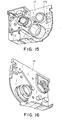
- Figure 15 is a perspective view of the inward side of the rear cover of the development unit.
- Figure 16 is a perspective view of the inward side of the front cover of the development unit.
- Figure 17 is a side view of the development unit.
- Figure 18 is a front view of the supporting portion for a development sleeve.
- Figure 19 is a vertical sectional view of the supporting portion for the electrophotographic photosensitive drum, and a driving apparatus for the electrophotographic photosensitive drum.
- Figure 20 is a perspective view of the drum flange on the driven side.
- the longitudinal direction means the direction perpendicular to the direction in which recording medium is conveyed, and parallel to the surface of the recording medium.
- the left or right side means the left or right side of the recording means as seen from above, and upstream in terms of the conveyance direction of the recording medium.
- the top side of a process cartridge means the top side of a process cartridge after the process cartridge is properly installed.
- FIG. 1 is a schematic sectional view of an image forming apparatus to which the present invention is applicable.
- the image forming apparatus in this drawing is provided with image forming portion 31Y, 31M, 31C and 31Bk for forming a toner image on a photosensitive drum, i.e., an image bearing member, an intermediary transfer belt 4a onto which the toner image is temporarily transferred, a secondary transfer roller 40, i.e., a transferring means, for transferring the toner image on the belt 4a, onto a recording medium 2, a sheet feeding means for conveying and feeding the recording medium 2 between the intermediary transfer belt 4a and secondary transfer roller 40, a conveying means for conveying the recording means 2 to the transferring means, a fixing means, and a sheet discharging means.
- a photosensitive drum i.e., an image bearing member
- an intermediary transfer belt 4a onto which the toner image is temporarily transferred
- a secondary transfer roller 40 i.e., a transferring means, for transferring the to
- the image forming apparatus comprises a sheet feeder cassette 3a, which is capable of storing plural sheets of recording medium 2 (for example, recording paper, OHP sheet, fabric, or the like), and is removably installable in the image forming apparatus.
- the sheets of recording medium are fed out of the sheet feeder cassette 3a by a pickup roller 3b, and are conveyed to a retard roller pair 3b, which separates the recording medium sheets and releases them one by one.
- the recording sheets are conveyed one by one to a registration roller pair 3g, by conveyer rollers 3d and 3f.
- the registration roller pair 3g At the moment of the arrival of the conveyed recording medium 2 at the registration roller pair 3g, the registration roller pair 3g is standing still, and as the recording medium 2 comes into contact with the nip of the registration roller pair, if it is skewed, it is correctly aligned.
- the toner images on the intermediary transfer belt 4a are transferred onto the recording medium 2 which is delivered to the nip between the secondary transfer roller 40 and the intermediary transfer belt 4a, with a predetermined timing. Then, the toner images are fixed to the recording medium 2, in a fixing apparatus, and then, the recording medium 2 is discharged into the tray 6 located at the top of the apparatus main assembly 14, by a pair of discharge rollers 3h and 3i.
- the components, exclusive of the optical scanning system (1Y, 1M, 1C or 1Bk), are components of a process cartridge (BY, BM, BC and BB). Since all the process cartridges in this image forming apparatus are the same in structure, the process cartridge structure will be described with reference to the process cartridge BY.
- a charging means, an exposing portion, a developing means, and a transfer opening are arranged around the peripheral surface of a photosensitive drum 7.
- two component developer which contains magnetic carrier is used. Therefore, an organic photoconductor or the like, which is commonly used, can be used as the material for the photosensitive drum 7, it is desired that the surface of the photosensitive material of the photosensitive drum 7 is coated with a surface layer, the electrical resistance of which is in a range of 10 2 - 10 14 cm.
- amorphous silicon is used as the photosensitive material for the photosensitive drum 7. This is because such a photosensitive drum makes it possible for electrical charge to be injected into the photosensitive drum 7, contributing to the prevention of ozone generation and reduction in electrical energy consumption. It also can improve charge efficiency.
- the photosensitive drum 7 in this embodiment was formed by coating negatively chargeable organic material on the peripheral surface of an aluminum drum.
- the charging means is a magnetic brush type charging device which employs magnetic carrier.
- the charging device 8 comprises a charge roller 8a, which is a hollow cylindrical roller and is rotatively supported, and a magnet 8b fixedly placed within the charge roller 8a. After the primary transfer, the toner which remains on the peripheral surface of the photosensitive drum 7 is taken into the charging device 8 which rotates in the direction indicated by an arrow mark.
- the developing means 10 in this embodiment a method which uses a two component magnetic brush for developing latent image, is employed (two component based non-contact development).
- Figure 2 also shows the developing means 10 in this embodiment, which uses the two component magnetic brush.
- a development sleeve 10d is a hollow cylindrical member, and is rotatively supported. Within the development sleeve 10d, a magnet 10c is fixedly disposed.
- the development sleeve 10d is rotated in the same direction as the photosensitive drum 7. More specifically, the development sleeve 10d and photosensitive drum 7 are rotated in such directions that the peripheral surfaces of the development sleeve 10d and photosensitive drum 7 move in the opposite directions at the point where they come closest to each other.
- the photosensitive drum 7 and development sleeve 10d remain not in contact with each other; a gap in a range of 0.1 - 1.0 mm is maintained between them so that developer is allowed to contact the peripheral surface of the photosensitive drum 7 to develop the image on the peripheral surface of the photosensitive drum 7.
- Toner mixed with carrier is placed in a casing partitioned with partitioning wall 10 which extends in the longitudinal direction.
- stirring screws 10g and 10h are provided to move the toner within the casing. After being supplied into the casing from an unillustrated toner supply container, the toner lands in the casing, adjacent to one of the longitudinal ends of the stirring screw 10g, and then, is conveyed toward the other longitudinal end, while being stirred, by the stirring screw 10g.
- the toner moves into the space on the other side of the partitioning wall 10, through the hole in the partitioning wall 10f, and then, is conveyed, while being stirred, by the stirring screw 10h, back to the opposite longitudinal end, i.e., the longitudinal end from which it began to be conveyed. Then, the toner moves back into the original space through another hole in the partitioning wall 10. In other words, the toner is circulated, while being stirred, in the casing, by the stirring screws 10g and 10h.
- the development process for visualizing the electrostatic latent image formed on the photosensitive drum 7, with the use of a developing apparatus 4 which employs a developing method based on a magnetic brush comprising two components, will be described along with the system for circulating the developer.
- the developer is picked up to the peripheral surface of the development sleeve 10d by the poles of the magnet 10c.
- the developer on the peripheral surface of the development sleeve 10d is regulated in thickness by a regulating blade 10e positioned perpendicular to the peripheral surface of the development sleeve 10d.
- a thin layer of developer is formed on the peripheral surface of the development sleeve 10d.
- the developer particles in the thin layer of developer aggregate in the form of a brush, across the portion correspondent to the primary pole of the magnet, i.e., the development pole, of the magnet 10c.
- the latent image on the photosensitive drum 7 is developed (visualized) by the toner particles in this aggregate of developer particles in the form of a brush, into a toner image.
- the thin layer of developer is returned to the developer container 10a by the repulsive magnetic field.
- DC and AC voltages are applied from unillustrated power sources.
- application of AC voltage generally increases development efficiency, and improves image quality.
- it creates an environment -in which a resulting image tends to suffer from "fog".
- difference in potential level is provided between the DC voltage applied to the development sleeve 10d, and the surface charge of the photosensitive drum 7, so that toner is prevented from adhering to the non-image areas of the photosensitive drum 7 during the development process.
- the thus developed toner image is transferred onto the intermediary transfer belt 4a by the intermediary transferring apparatus 4, which comprises an endless belt 4a, a driver roller 4b, a follower roller 4c, and a counter roller 4d for secondary transfer.
- the endless belt 4a are stretched around the rollers 4b, 4c and 4d, and is rotatively driven in the direction indicated by an arrow in Figure 1.
- transfer charge rollers 4Y, 4M, 4C and 4Bk are disposed in contact with the belt 4a, on the inward side of the belt loop, to apply pressure upon the belt 4a, against the photosensitive drum 7, while being supplied with voltage from a high voltage source, that is, while being charged to the polarity opposite to the polarity of the toner.
- the toner images on the photosensitive drums 7 in the process cartridges are sequentially transferred onto the intermediary transfer belt 4a, on the top side.
- polyimide As for the material for the intermediary transfer belt 4a, polyimide can be used. However, it does not need to be limited to polyimide.
- other dielectric plastics such as polycarbonate, polyethylene terephthalate, polyfluorovinylidene, polyethylene-naphthalate, polyether ether keton, polyethersulfon, and polyurethane, and rubber such as fluorinated rubber and silicon rubber, may be used with good results.
- transfer-residual toner After the image transfer, a certain amount of toner remains on the peripheral surface of the photosensitive drum 7 (transfer-residual toner). If this transfer-residual toner is passed as it is through the charging device, the photosensitive drum 7 fails to be charged to the predetermined potential level, across the portions correspondent to the residual image (residual toner image) during the following image formation, and/or the following image becomes light or dark, across the portions correspondent to the preceding image (hereinafter, this phenomenon is called ghost). In other words, even after the transfer-residual toner passes through the charging station in which the charging magnetic brush is in contact with the photosensitive drum 7, the residual image, or the image formed by the residual toner, remains virtually undisturbed.
- the residual toner on the photosensitive drum 7 is a mixture of the positively charged toner particles and the negatively charged toner particles, which are created by the separation discharge or the like which occurs during the transfer process, it is desired, in consideration of the ease with which the transfer-residual toner can be taken into the magnetic brush based charging device 8, that the polarity of the transfer-residual toner is positive.
- an electrically conductive brush 11 is placed in contact with the photosensitive drum 7, between the intermediary transferring apparatus 4 and magnetic brush based charging device 8, to apply bias having the polarity opposite to the charge bias.
- the positively charged toner particles in the transfer-residual toner pass the magnetic brush based charging device 8, whereas the negatively charged toner particles in the transfer-residual toner are temporarily captured by the electrically conductive brush 11, being thereby robbed of their negative polarity, and then, are spit out back onto the photosensitive drum 7. This process makes it easier for the transfer-residual toner to be attached to the magnetic brush.
- the process cartridge B (BY, BM, BC and BB) in this embodiment comprises a development unit D and a charge unit C, which are connected to each other.
- the development unit D is provided with an electrophotographic photosensitive drum 7, a developing means 10, and a development unit frame 12 in which the drum 7 and developing means 10 are mounted.
- the charge unit C is provided with a charge roller 8a, a regulator blade 8c, a charge brush 11, and a charge unit frame 13 in which the roller 3a, blade 8c, brush 11, and the like, are mounted.
- the connected development unit D and charge until C are covered on the front and rear sides, with a front cover 16 and cover 17 ( Figure 4), respectively, to properly position them relative to each other.
- the process cartridge B is also provided with a shutter 18, which covers or exposes a transfer opening by moving between positions (a) and (b), respectively.
- the transfer opening is provided between the development unit frame 12 and charge unit frame 13.
- the shutter 18 is a component which prevents the photosensitive drum 7 from being damaged by its exposure to the external light, or due to mishandling, when the process cartridge B is out of the image forming apparatus, and which opens to allow the photosensitive drum 7 to make contact with the intermediary transfer belt 4a after the installation of the process cartridge B into the main assembly 14 of the image forming apparatus.
- the transfer-residual toner electrically adheres to the electrically conductive brush 11, on the side of the intermediary transferring apparatus 4. If the transfer-residual toner adheres to the electrically conductive brush 11, by a certain amount or more, the toner falls off due to the vibration which occurs when the process cartridge B is removed from the apparatus main assembly 14, or is moved, and the fallen toner contaminates the hands and clothes of the user, the surfaces of the desk or floor on which the process cartridge B is placed when the process cartridge B is exchanged.
- the shutter 18 is also effective to prevent this kind of problem.
- Figures 3 - 7 are projected plans of the process cartridge B (BY, BM, BC and BB): Figure 3 is a front view; Figure 4, a right side view; Figure 5, a left side view; Figure 6, a top view; and Figure 7 is a rear view.
- Figures 8 - 10 are external perspective views of the process cartridge B: Figure 3 is a view as seen from diagonally above the right front corner; Figure 9, a view as seen diagonally above the right rear corner; and Figure 10 is an upside down view as seen from diagonally above the right rear. In Figures 3 - 10, the shutter 18 is not illustrated.
- the charge unit C comprises the charge unit frame 13, and the charge roller 8a, regulator blade 8c, and electrically conductive brush 11 which are integrally disposed in the charge unit frame 13.
- the charge unit frame 13 constitutes a part of the external shell of the process cartridge B.
- the bottom corner wall 13a of the charge unit frame 13 extends in the longitudinal direction of the process cartridge B, in parallel to the photosensitive drum 7, holding a small gap from the peripheral surface of the photosensitive drum 7. From this bottom corner wall 13a, the wall 13b virtually vertically extends upward, and curves inward at the top, forming a corner portion 13c.
- a top wall 13d extend virtually horizontally, providing the charging unit frame 13 with an approximately key-shaped cross section. There is an empty space under the top wall 13d.
- the charge unit frame 13 is also provided with component attachment portions 13e and 13f, which are integrally formed with the charge unit frame 13, being located at the longitudinal ends, one for one.
- FIG 11 is a side view of the charge unit c as seen from inside.
- the charge unit frame 13 is provided with a charge roller bearing 22 and an end cover 23, which are attached to the longitudinal end of the charge unit frame 13, with the use of the screws put through both bearing 22 and cover 23, on the trailing side in terms of the direction in which the process cartridge B is installed in the apparatus main assembly 14 (process cartridge B is installed in the longitudinal direction from the front side of the apparatus main assembly 14).
- the other longitudinal end of the charge unit C is provided with a gear unit 24, which is fixed to the charge unit frame 13 also with the use of screws.
- a pair of blade attachment seats 13g i.e., flat portions, which are slightly raised from the component attachment portions 13e and 13f, are provided with a female screw 13h and a dowel-like projection 13ia.
- the charge unit C is also provided with a pair of sealing members 21b, which are formed of such material as felt, and are pasted to the longitudinal ends of the charge unit frame 13, one for one, along the internal surface of the semicylindrical sealing portion 8a1 located at the longitudinal ends of the charge roller 8a, to prevent the developer from leaking out of the process cartridge B along the peripheral surface of the shaft of the charge roller 8a. Therefore, the contour of the cross-section of the portion of the charge unit frame 13, perpendicular to the longitudinal direction of the process cartridge B, is in the form of an arc, the focus of which is on the axial line of the charge roller 8a.
- the regulator blade 8c which is formed of metallic material, is fixed to the metallic supporting plate 8d with the use of a small screw 8j, holding a small gap from the charge roller 8a.
- the metallic supporting plate 8d has a groove-like cross section. It is fitted around the dowel-like projection 13i of the seat portion 13g of the charge unit frame 13, and as a small screw 8k put through the hole of the metallic support plate 8d is screwed into the female threaded hole 13h of the seal portion 13g, the metallic supporting plate 8d comes into contact with the seat portion 13g, while compressing the sealing member 21a. Also during this attachment of the metallic supporting plate 8d, the sealing member 21a is compressed by the metallic supporting plate 8d, across the portion adjacent to the seat portion 13g.
- the metallic supporting plate 8d is extremely high in rigidity, and fixing it to the charge unit frame 13 by both longitudinal ends adds to the rigidity of the charge unit frame 13.
- the charge unit C is supported by the development unit frame 12, being enable to pivot about a pivotal axis SC illustrated in Figure 2. Therefore, a gear unit 24 fixed to the charge unit frame 13, at the longitudinal end on the rear side, is provided with a cylindrical shaft portion 26a, the position of which corresponds to the position of the aforementioned pivotal axis SC, whereas the end cover 23 at the other longitudinal end of the charge unit frame 13 is provided with a cylindrical hole 23a, the position of which corresponds to the position of the pivotal axis SC, as shown in Figure 11.
- the development unit frame 12 comprises a bottom portion 12f, a side wall portion 12g, an end wall 12h (rear), and an end wall 12i (front).
- the bottom portion 12 holds the aforementioned stirring screws 10g and 10h separated by the partitioning wall 10f, and has a pair of seat portions 12e to which the regulator blade 10e is attached.
- the side wall portion 12g constitutes the left side wall of the process cartridge B as seen from the upstream side in terms of the direction in which the process cartridge B is installed.
- the end walls 12h and 12i constitute the longitudinal end portions of the process cartridge B as shown in Figures 13, 14, 17 and 18.
- the end wall portion 12h is provided with a hole 12j, in which a bearing is fitted to rotatively support the aforementioned cylindrical shaft portion 26a of the charge unit C.
- the end wall portion 12i is provided with a hole 12m, the diameter of which is the same as that of the cylindrical hole 23a of the charge unit frame 13.
- the rear cover 17 that is, the cover on the leading side in terms of the direction in which the process cartridge B is installed, is aligned with the longitudinal end portion of the development unit frame 12 so that a shaft supporting portion 17a in the form of a hollow cylinder projecting in the longitudinal direction, in the space within the rear cover 17 ( Figures 11 and 15), fits in the hole 12j of the development unit frame 12, and the cylindrical shaft portion 26a fits into the cylindrical hollow of the shaft supporting portion 17a.
- a supporting shaft 27 ( Figures 11 and 14) is put through the hole 12m of the end wall portion 12i of the development unit frame 12, so as to project inward from the hole 12m, and fit into the hole 23a of the charge unit C.
- the charge unit C is pivotally supported by the development unit frame 12; the cylindrical shaft portion 26a, that is, one of the longitudinal end portions, of the charge unit C is rotatively supported by the end cover 17, and the wall of the hole 23a of the charge unit C, on the other longitudinal end, is supported by the supporting shaft 27.
- the top wall 29 is fixed to the development unit frame 12 with the use of small screws 28, so that the edges of the top wall 29 fit with the guide portion 12a, that is, the top portion of the side wall 12g, and the end walls 12h and 12i, on the inward side.
- the top wall 29 is provided with a pair of spring seats 29a which are aligned in the longitudinal direction, and each of which holds a compression spring 30, so that the spring 30 is kept compressed between the top wall 29 and charge unit frame 13.
- the charge unit C is kept under the pressure generated by these coil springs 30 in the direction to pivot the charge unit C about the pivotal axis SC in the clockwise direction.
- each longitudinal end of the charge roller 8a is provided with a journal portion 8a2, which is smaller in diameter than the main portion of the charge roller, is coaxial therewith, and is fitted with a freely rotating spacer ring 8n.
- the spacer ring 8n is kept in contact with the peripheral surface of the photosensitive drum 7, on the portion outside the image formation range, by the resiliency of the aforementioned compression springs 30.
- the charge roller 8a and photosensitive drum 7 are rotated in such directions so that the movements of their peripheral surfaces become opposite to each other where the gap between them is smallest, and the transfer-residual toner which enters where the distance between the peripheral surfaces of the charge roller 8a and photosensitive drum 7 is smallest is caught by the application of charge bias.
- the line connecting the pivotal axis SC and the center of the charge roller 8a is virtually perpendicular to the line connecting the centers of the charge roller 8a and photosensitive drum 7.
- each longitudinal end of the development sleeve 10d is provided with a journal portion 10d1, which is smaller in diameter than the main portion of the development sleeve 10d, and is fitted with a spacer ring 10j greater in radius by an amount equal to the development gap than the main portion.
- the journal 10d1 is also fitted with a pivotal arm 32, which is on the outward side of the spacer ring 10j.
- FIG 18 is a sectional view of the pivotal arm 32 and its adjacencies, at a plane perpendicular to the development sleeve 10d, the base portion of the pivotal arm 32 is pivotally supported by a supporting axis 33 (pivot axis) put through the development unit frame 12 in the longitudinal direction and press-fitted in both end walls 12h and 12i of the development unit frame 12.
- the pivotal arm 32 is provided with a bearing hole, which is located approximately straight above the supporting shaft 33, and a stopper portion 32b, which is located above the bearing hole 32a.
- the pivotal arm 32 is also provided with a spring seat 37c, the surface of which is approximately perpendicular to the line connecting the pressure application center Slv, i.e., the center of the supporting shaft 33, and the center of the bearing hole 32a.
- the journal portion 10d1 located at each longitudinal end of the development sleeve 10d is rotatively supported in the bearing hole 32a of the pivotal arm 32.
- the compression spring 35 is placed in the compressed state.
- the pivotal arm 32 is kept under the pressure generated by the compressing spring 35 in the direction to pivot the pivotal arm 32 about the pressure application center Slv (center of the supporting shaft 33) toward the photosensitive drum 7, which in turn keeps the spacer rings 10j, fitted around the development sleeve 10d, in contact with the peripheral surface of the photosensitive drum 7, on the portion outside the image formation range.
- a predetermined gap (0.2 - 10 mm) is maintained between the peripheral surface of the development sleeve 10d and photosensitive drum 7.
- the aforementioned stopper portion 32b prevents the pivotal arm 32 from pivoting outward ( Figure 18) of the development unit frame 12, by coming into contact with the development sleeve cover 36, when assembling or disassembling the process cartridge B. Thus, after the completion of the assembly of the process cartridge B, the stopper portion 32b is not in contact with the development sleeve cover 36.
- the development sleeve cover 36 extends from the pivotal arm 32 on the front side to the one on the rear side, and is fixed to the development unit frame 12 with screws.
- the top portion of the process cartridge B is provided with guiding portions 12a and 29b in the form of a flange, which extend along the left and right sides, respectively, as seen from the trailing side in terms of the process cartridge B installation.
- guiding portions 12a and 29b engage with correspondent unillustrated guide rails which extend perpendicular to the plane of Figure 1, when the process cartridge B is installed into, or removed from, the main assembly of the image forming apparatus.
- the process cartridge B is provided with electrical contacts, which come into contact with the correspondent electrical contacts on the apparatus main assembly side which are connected to an unillustrated high voltage power source provided on the apparatus main assembly side, as the process cartridge B is installed into the apparatus main assembly 14.
- the process cartridge B is provided with a drum ground contact 101, which is on the trailing side in terms of the direction in which the process cartridge B is installed, and is connected to photosensitive drum 7.
- the process cartridge B is provided with a contact 102 for the electrically conductive brush, which is connected to the electrically conductive brush 11, a charge bias contact 103 which is connected to the charge roller 8a, and a development bias contact 104 which is connected to the development sleeve 10d.
- the contacts 102, 103 and 104 are on the rear side, i.e., the leading side in terms of the direction in which the process cartridge B is installed.
- the process cartridge B is also provided with an I.C.
- the connector 105 is connected with the unillustrated connector on the apparatus main assembly side as the process cartridge B is installed into the apparatus main assembly 14, so that the controlling apparatus on the apparatus main assembly side is allowed to write the usage history of the installed process cartridge B into the I.C. equipped connector 105, or to read it therefrom, to control the image forming operation.
- the process cartridge B is provided with three driving power receiving portions in the form of a coupler, the rotational axes of which coincide with the rotational axes of the correspondent components. They are located on the rear side, that is, the leading end side in terms of the direction in which the process cartridge B is installed. As the process cartridge B is installed into the apparatus main assembly 14, the three driving force receiving portions are connected with the correspondent driving force transmitting members of the apparatus main assembly 14.
- the rear side of the process cartridge is provided with a drum coupling 37d, a charging portion coupling 38, and a development portion coupling 39, which are exposed from the rear wall of the process cartridge B.
- the drum coupling 37d is provided at the longitudinal end of the drum flange 37 fixed to the logitudinal ends of the photosensitive drum 7.
- FIG 19 depicts a method for supporting the photosensitive drum 7, and a method for driving the photosensitive drum 7.
- the photosensitive drum 7 comprises a hollow aluminum cylinder 7a, and a layer of photosensitive substrate coated on the peripheral surface of the aluminum cylinder 7a.
- the photosensitive drum 7 is provided with a pair of drum flanges 37 and 41, which are filed to the longitudinal ends of the photosensitive drum 7, on the driven and non-driven sides, respectively, by pressing their smaller diameter portions into the aluminum cylinder 7a.
- the drum shaft 42 is put through the centers of the drum flanges 37 and 41.
- One end of the drum shaft 42 is fitted through a through hole 12b with which the end wall portion 12i of the development unit frame 12 is provided.
- a pin 43 is pressed through a through hole made in the drum shaft 42, in the radial direction, and is exactly fitted in a straight groove which is located in the outwardly facing surface of the drum flange 41 on the non-driven side, and extends outward in both directions from the center of drum flange 41 on the non-driven side.
- the drum flange 41 on the non-driven side is provided with an electrically conductive spring 44, which is fixed to the inwardly facing surface of the drum flange 41.
- the electrically conductive spring 44 is fitted around the dowel-like projection 41b with which the drum flange 41 is provided, and then, the dowel-like projection 41b is melted and solidified.
- One end of the electrically conductive spring 44 remains in contact with the inward surface of the drum cylinder 7a because of the resiliency of the spring 44, and the other end of the spring 44 remains in contact with the drum shaft 42 also because of the resiliency of the spring 44.
- One end of the drum grounding contact 101 attached to the end wall portion 12i of the development unit frame 12 remains in contact with the drum shaft 42 because of the resiliency of the contact 101.
- the other end of this drum grounding contact 101 with which the development unit frame 12 is provided is exposed from the process cartridge B, and serves as an external contact.
- the end wall portion 12i is provided with a straight groove 12c, which radially extends from the drum shaft supporting through hole 12b in both directions, so that the pin 43 can be put through the end wall portion 12i in the axial direction of the photosensitive drum 7 during the assembly of the process cartridge B.
- the drum flange 37 on the driven side comprises an attachment portion 37a which fits into the drum cylinder 7a, a rib portion 37b which comes into contact with the longitudinal end of the drum cylinder 37a, a journal portion 37c with a diameter smaller than that of the rib portion 37b, and male coupler portion 37d which projects in the axial direction of the photosensitive drum 7 from the center portion of the outward surface of the journal portion 37c, in the listed order from the inward side.
- the drum flange 37 on the driven side is a molded single piece component.
- the journal portion 37c is rotatively fitted in the shaft supporting portion 17a which is an integral part of the rear cover 17 inserted into the hole 12d of the end wall portion 12h of the development unit frame 12, with the interposition of a collar 56 between the journal portion 37c and shaft supporting portion 17a.
- the male coupler portion 37d is in the form of a twisted equilateral triangular prism.
- the diameter of the circumcircle of this male coupler portion 37d is smaller than that of the journal portion 37c.
- the driving apparatus with which the apparatus main assembly 14 is provided comprises a motor 45 anchored to the apparatus main assembly, a pinion gear 46, an intermediary gear 47, a large gear 48, a shaft 49 for the large gear 48, a bearing 51 for supporting the shaft 49 for the large gear 48, and a female coupler shaft 52.
- the intermediary gear 47 is meshed with the pinion gear 46 and large gear 48, and is rotatively supported.
- the shaft 49 for the large gear 48 is fixed to the large gear 48, and is provided with an axis aligning portion 57, which is press fitted with the inward end of the shaft 49.
- the bearing 51 supports the shaft 49 for the large gear 48 so that the latter does not move in the axial direction.
- the female coupler portion 52a is provided with a hole in the form of a twisted equilateral triangular prism, into, or from, which the male coupler portion 37d is engaged or disengaged in the axial direction.
- the male coupler portion 37d engages into the female coupler portion 52b, the longitudinal edges of the male coupler portion 37d in the form of an equilateral triangular prism make contact with the correspondent surfaces of the hole of the female coupler portion 52a, in the form of an equilateral triangular prism.
- the rotational axis of the male coupler portion 37d becomes aligned with the rotational axis of the female coupler portion 52a.
- the female coupler shaft 52 is kept under the pressure generated by a spring in the direction to move the shaft 52 toward the process cartridge B, and therefore, it remains at the innermost position within the range in which it is allowed to move in the axial direction, although it is enabled to be moved outward against the resiliency of the spring (details are omitted).
- the portion of the drum shaft 42, by which the drum shaft 42 is supported on the non-driven side, is structured so that the drum shaft 42 does not move toward the non-driven side. More specifically, the drum shaft 42 is fitted with a stopper ring 53 as shown in the drawing. A gearing 55 fitted in a gearing case 54 fixed to the front cover 16 fixed to the end wall portion 12i of the development unit frame 12 is fitted around the drum shaft 42, and the drum shaft 42 is prevented from moving toward the non-driven side as the outward surface of the shaft stopper ring 53 comes into contact with the inward surface of the bearing case 54, in terms of the axial direction. In comparison, the movement of the photosensitive drum 7 toward the driven side is controlled by the collar 56 fitted around the journal portion 37c of the drum flange 37.
- the distance between the shaft supporting portion 17a and bearing 55 is rendered larger than the distance between the surface of the shaft stopper ring 53, which faces the bearing 55, and the surface of the collar 56, which faces the shaft supporting portion 17a, so that the photosensitive drum7 is allowed to move a limited distance in the axial direction.
- the cartridge frame (development unit frame 12, front cover 16, and rear cover 17) is precisely positioned relative to the apparatus main assembly 14 in terms of the longitudinal direction. Further, the end portion 42a of the drum shaft 42 fits into the center hole 57a of the axis aligning portion 57, and the male coupler portion 37d fits into. the female coupler portion 52a. Then, as the motor rotates, the pinion gear 46, intermediary gear 47, and large gear 48 rotate, causing the female coupler shaft 52 to rotate through the gear shaft 49 for the large gear 48, and the axis aligning portion 57.
- the end portion of the male coupler portion 37d comes into contact with the bottom surface of the female coupler portion 52a, because the male and female coupler portions 37d and 52a are both in the form of a twisted triangular prism, and the directions of their twist are such that the male coupler portion 37d is enabled to be screwed into the female coupler portion 52a.
- the photosensitive drum 7 is accurately positioned in the axial direction relative to the accurately positioned female coupler shaft 52.
- the male coupler portion 37d does not engage with the female coupler portion 52b immediately after the installation of the process cartridge B into the apparatus main assembly 14, the inward surface of the male coupler portion 37d presses upon the edge of the female coupler portion (hole) 52a of the female coupler shaft 52, and therefore, the female coupler shaft 52 is caused to move away from the process cartridge B against the resiliency of the spring which presses the female coupler shaft 53 toward the process cartridge B.
- the male coupler portion 37d and female coupler portion 52a instantly engage with each other the moment they synchronize in rotational phase.
- the above structure may be modified so that, as the photosensitive drum 7 is pulled toward the female coupler shaft 52 by the force generated by the rotational engagement between the two coupler portions, the photosensitive drum 7 is correctly positioned by the contact between the collar 56 fitted around the journal portion 37c of the drum flange 37, in contact with the rib 37b, and the shaft supporting portion 17a of the rear cover 17, instead of the contact between the inward surface of the male coupler portion 35d and the bottom surface of the female coupler portion (hole) 52a.
- this embodiment was described with reference to a process cartridge which integrally comprises a developing means, and a charging means capable of recovering toner, along with a photosensitive drum.
- the structural configuration in this embodiment that is, the structural configuration for supporting a photosensitive drum with the cartridge frame, and the structural configuration for engaging the driving force receiving portion of the photosensitive drum with the driving member on the image forming apparatus main assembly side, or disengaging them, are also applicable to most process cartridges.
- the process cartridge mentioned in this specification means a cartridge which integrally comprises a charging means, a developing means or cleaning means, and an electrophotographic photosensitive drum, and is removably installable into the main assembly of an image forming apparatus, a cartridge which integrally comprises at least a charging means, a developing means, or a leaning means, in addition to an electrophotographic photosensitive drum, and is removably installable into the main assembly of an image forming apparatus, or a cartridge which integrally comprises at least a developing means and an electrophotographic photosensitive drum, and is removably installable into the main assembly of an image forming apparatus.
- the process cartridge B is removably installable in the main assembly 14 of an image forming apparatus, and comprises:
- the frame 13 for supporting the charging means 8 is pivotally supported by the frame 12 for supporting the developing means 10. Therefore, the charging means and electrophotographic photosensitive drum are correctly positioned relative to each other.
- the charging means 8 comprises a charge roller 8a, and the pivotal axis of the frame 13 for supporting the charging means 8 is on the straight line perpendicular to the line connecting the center of the photosensitive drum 7 and the center of the charge roller 8n.
- the charge roller 8a is fitted with a pair of rings 8e which make contact with the electrophotographic photosensitive drum 7 to secure a predetermined gap between the electrophotographic photosensitive drum 7 and charge roller 8a, and a spring 30 as an elastic member for keeping the charge roller 8a pressed upon the electrophotographic photosensitive drum 7 is provided between the frame 13 for supporting the charging means 8, and the frame 12 for supporting the developing means 10. Therefore, the charge unit is simple in structure.
- the charging means 8 comprises a magnetic brush type charging device which uses magnetic carrier.
- the charging means 8 comprises an electrically conductive brush 11, which is on the upstream side of the magnetic brush type charging device in terms of the moving direction of the peripheral surface of the electrophotographic photosensitive drum 7.
- bias which is opposite in polarity to the charge bias is applied to the electrically conductive brush 11.
- the frame for supporting the charging means 8 comprises the charge unit frame 13 which extends in the longitudinal direction of the charge roller 8a along the charge roller 8, a bearing 22 for supporting the charge roller 8a fixed to one end of the charge unit frame 13, an end cover 23 provided with a hole 23a which is fixed to the frame 13, on the outward side of the bearing 22, and serves as the pivotal center of the frame 13 for supporting the charging means 8, and a gear case 26 which comprises a cylindrical hollow portion 26a, is fixed to the other end of the charge unit frame 13, and serves as the pivotal center of the frame 13 for supporting the charging means 18.
- the gear case 26 is provided with a gearing portion for supporting the charge roller 8a.
- a driving force receiving portion is disposed in the cylindrical hollow portion 26a of the gear case 26.
- the gear case 26 supports a gear train 24G which delivers driving force to the internal components of the process cartridge B, ranging from the driving force receiving portion to the charge roller 8a.
- the frame for supporting the developing means 10 comprises: the development unit frame 12 for supporting the development sleeve 10d of the developing means 10, the development blade 10e, the electrophotographic photosensitive drum 7, and the charge unit C; and the front and rear covers 16 and 17, that is, the end covers fixed to the corresponding longitudinal ends of the development unit frame 12.
- the electrophotographic photosensitive drum 17 is provided with a projection in the form of a twisted equilateral polygonal prism, which is attached to one of the longitudinal ends of the electrophotographic photosensitive drum 7, and serves as the driving force receiving portion, and the rear cover 7, that is, the end cover, which is fixed to one of the longitudinal ends of the development unit frame 12, is provided with a hole through which the polygonal projection 37d is exposed.
- the rear cover 17, that is, the end cover, which is fixed to one of the longitudinal ends of the development unit frame 12, is provided with a hole through which the driving force receiving portion of the charge unit C is exposed.
- the frame 12 for supporting the developing means 10 is provided with a means for installing the process cartridge B into the image forming apparatus main assembly 14, or removing the process cartridge B therefrom.
- the means for installing or removing the process cartridge B, into or from, the image forming apparatus main assembly 14 comprises guiding portions 12a and 29b, which extend in the longitudinal direction of the process cartridge B, and are moved out of, or into, the image forming apparatus main assembly 14, along the guide rails provided in the image forming apparatus main assembly 14.
- the guides 12a and 29b are located, one for one, at the longitudinal top edges of development unit frame 12.
- the development unit frame 12 is provided with a top wall 29, which is fixed to the main structure of the development unit frame 12, and the guiding portion 12a is a part of the main structure of the development unit frame 12, whereas the guiding portion 29b is a past of the top wall 29.
- the contour of the cross section of the development unit frame 12, at a plane perpendicular to the longitudinal direction of the development unit frame 12, is approximately rectangular. Therefore, the process cartridge is smaller in width, which contributes to the size reduction for a multi-color image forming apparatus.
- a unit combined with a charging means 8 to form a process cartridge B comprises:
- the frame 12 for supporting the developing means 10 is provided with a supporting portion for pivotally supporting the frame 13 for supporting the charging means 8 of the process cartridge B.
- a unit embodiment with a developing means 10 to form a process cartridge B comprises:
- the frame 13 for supporting the charging means 8 is provided with a supporting portion for pivotally supporting the frame 12 for supporting the developing means.
- the electrophotographic photosensitive drum is supported by a development unit frame with a high degree of rigidity. Therefore, the electrophotographic photosensitive drum is correctly positioned, which contributes to the production of high quality images.
- the charging means is in the form of a charge unit. Therefore, an accurate gap is established between the charging means and the electrophotographic photosensitive drum, and the charging means is greater in rigidity. Also, the charge unit and development unit can be separately assembled to be connected later, simplifying the assembly process.
Landscapes
- Physics & Mathematics (AREA)
- General Physics & Mathematics (AREA)
- Engineering & Computer Science (AREA)
- Computer Vision & Pattern Recognition (AREA)
- Electrophotography Configuration And Component (AREA)
- Dry Development In Electrophotography (AREA)
- Electrostatic Charge, Transfer And Separation In Electrography (AREA)
Applications Claiming Priority (2)
| Application Number | Priority Date | Filing Date | Title |
|---|---|---|---|
| JP37256398 | 1998-12-28 | ||
| JP10372563A JP2000194248A (ja) | 1998-12-28 | 1998-12-28 | プロセスカ―トリッジ及び帯電ユニット及び現像ユニット |
Publications (2)
| Publication Number | Publication Date |
|---|---|
| EP1016943A2 true EP1016943A2 (fr) | 2000-07-05 |
| EP1016943A3 EP1016943A3 (fr) | 2001-05-16 |
Family
ID=18500658
Family Applications (1)
| Application Number | Title | Priority Date | Filing Date |
|---|---|---|---|
| EP99310457A Withdrawn EP1016943A3 (fr) | 1998-12-28 | 1999-12-22 | Unité de traitement et appareil électrophotographique de formation d'images |
Country Status (5)
| Country | Link |
|---|---|
| US (1) | US6442359B1 (fr) |
| EP (1) | EP1016943A3 (fr) |
| JP (1) | JP2000194248A (fr) |
| KR (1) | KR20000052597A (fr) |
| CN (1) | CN1258865A (fr) |
Cited By (1)
| Publication number | Priority date | Publication date | Assignee | Title |
|---|---|---|---|---|
| EP1253485A2 (fr) | 2001-04-27 | 2002-10-30 | Canon Kabushiki Kaisha | Unité de traitement, appareil électrophotographique de formation d'images et procédé de fixation d'un élément de contact électrique |
Families Citing this family (49)
| Publication number | Priority date | Publication date | Assignee | Title |
|---|---|---|---|---|
| JP4545913B2 (ja) * | 2000-10-24 | 2010-09-15 | キヤノン株式会社 | スリーブユニット取付方法 |
| JP4677093B2 (ja) * | 2000-12-25 | 2011-04-27 | キヤノン株式会社 | プロセスカートリッジ |
| JP2003162203A (ja) * | 2001-09-13 | 2003-06-06 | Canon Inc | ユニット及び現像カートリッジ及びプロセスカートリッジ及びトナーカートリッジ及び電子写真画像形成装置 |
| JP3890227B2 (ja) * | 2001-12-21 | 2007-03-07 | キヤノン株式会社 | プロセス手段移動機構、帯電装置、プロセスカートリッジ及び電子写真画像形成装置 |
| JP2003215917A (ja) | 2002-01-24 | 2003-07-30 | Canon Inc | 現像装置、プロセスカートリッジ及び画像形成装置 |
| JP4072362B2 (ja) | 2002-03-14 | 2008-04-09 | キヤノン株式会社 | 現像装置及びプロセスカートリッジ及び画像形成装置 |
| JP3684209B2 (ja) | 2002-05-31 | 2005-08-17 | キヤノン株式会社 | カートリッジ及び電子写真画像形成装置 |
| KR100509499B1 (ko) * | 2002-06-15 | 2005-08-22 | 삼성전자주식회사 | 칼라화상형성장치 및 그를 이용한 칼라화상형성방법 |
| JP4314006B2 (ja) * | 2002-09-30 | 2009-08-12 | キヤノン株式会社 | 画像形成装置 |
| US6978100B2 (en) * | 2002-09-30 | 2005-12-20 | Canon Kabushiki Kaisha | Process cartridge, developing cartridge and developing roller |
| US6980755B2 (en) * | 2002-09-30 | 2005-12-27 | Canon Kabushiki Kaisha | Recycling method for developer supplying unit including the step of driving a feeding member in a direction to feed developer from a developer supply port to a developer accommodating portion |
| JP3809412B2 (ja) * | 2002-09-30 | 2006-08-16 | キヤノン株式会社 | 現像カートリッジ及び電子写真画像形成装置 |
| JP3913153B2 (ja) * | 2002-09-30 | 2007-05-09 | キヤノン株式会社 | 給電接点部材及びプロセスカートリッジ及び画像形成装置 |
| JP3720802B2 (ja) * | 2002-11-06 | 2005-11-30 | キヤノン株式会社 | プロセスカートリッジの再生産方法 |
| JP3747195B2 (ja) * | 2002-11-20 | 2006-02-22 | キヤノン株式会社 | プロセスカートリッジ及び電子写真画像形成装置 |
| US6801733B2 (en) * | 2003-01-21 | 2004-10-05 | Static Control Components, Inc. | Printer cartridge and method of making or refurbishing |
| JP3970217B2 (ja) * | 2003-08-29 | 2007-09-05 | キヤノン株式会社 | 電子写真画像形成装置 |
| JP4378221B2 (ja) * | 2003-10-08 | 2009-12-02 | キヤノン株式会社 | プロセスカートリッジ及び電子写真画像形成装置 |
| JP3673795B2 (ja) * | 2003-10-24 | 2005-07-20 | キヤノン株式会社 | 現像装置、プロセスカートリッジ、及び、画像形成装置 |
| JP4086766B2 (ja) * | 2003-11-28 | 2008-05-14 | キヤノン株式会社 | プロセスカートリッジ及びプロセスカートリッジ組立方法 |
| JP3782807B2 (ja) * | 2003-11-28 | 2006-06-07 | キヤノン株式会社 | プロセスカートリッジ、及び電子写真感光体ドラムの取り付け方法 |
| JP3885062B2 (ja) * | 2004-03-30 | 2007-02-21 | キヤノン株式会社 | 電子写真感光体ドラム、プロセスカートリッジおよび電子写真画像形成装置 |
| US7158749B2 (en) * | 2004-04-26 | 2007-01-02 | Canon Kabushiki Kaisha | Cleaning device, process cartridge, cleaning member and electrophotographic image forming apparatus |
| JP3885074B2 (ja) * | 2004-05-11 | 2007-02-21 | キヤノン株式会社 | 電子写真感光体ドラム、プロセスカートリッジ、及び電子写真画像形成装置 |
| JP3950882B2 (ja) * | 2004-10-06 | 2007-08-01 | キヤノン株式会社 | 電子写真画像形成装置 |
| JP4280770B2 (ja) | 2006-01-11 | 2009-06-17 | キヤノン株式会社 | プロセスカートリッジ及び電子写真画像形成装置 |
| JP4667444B2 (ja) | 2006-12-13 | 2011-04-13 | キヤノン株式会社 | 電子写真画像形成装置 |
| JP4095649B1 (ja) | 2006-12-28 | 2008-06-04 | キヤノン株式会社 | 電子写真画像形成装置、プロセスカートリッジ、及び移動部材 |
| JP4458378B2 (ja) | 2007-06-29 | 2010-04-28 | キヤノン株式会社 | プロセスカートリッジ及び電子写真画像形成装置 |
| JP4458377B2 (ja) | 2007-06-29 | 2010-04-28 | キヤノン株式会社 | プロセスカートリッジ及び電子写真画像形成装置 |
| JP4968957B2 (ja) * | 2008-03-31 | 2012-07-04 | キヤノン株式会社 | 枠体ユニット、現像装置及びプロセスカートリッジ、並びに、枠体ユニット、現像装置及びプロセスカートリッジの製造方法 |
| JP5106656B2 (ja) | 2010-06-22 | 2012-12-26 | キヤノン株式会社 | プロセスカートリッジ及び画像形成装置 |
| JP4846062B1 (ja) | 2010-08-20 | 2011-12-28 | キヤノン株式会社 | カートリッジ及び画像形成装置 |
| JP5950156B2 (ja) * | 2011-09-09 | 2016-07-13 | 株式会社リコー | プロセスカートリッジ、及び、画像形成装置 |
| KR101703103B1 (ko) | 2011-11-09 | 2017-02-06 | 캐논 가부시끼가이샤 | 카트리지 및 유닛 |
| JP2013122489A (ja) | 2011-11-09 | 2013-06-20 | Canon Inc | カートリッジ及びユニット |
| JP5962379B2 (ja) * | 2012-09-21 | 2016-08-03 | ブラザー工業株式会社 | 現像カートリッジおよびその製造方法 |
| JP6057651B2 (ja) | 2012-10-01 | 2017-01-11 | キヤノン株式会社 | プロセスカートリッジおよびプロセスカートリッジの製造方法 |
| JP6160325B2 (ja) * | 2013-07-19 | 2017-07-12 | ブラザー工業株式会社 | 現像カートリッジおよび像担持体カートリッジ |
| JP6415198B2 (ja) | 2013-09-12 | 2018-10-31 | キヤノン株式会社 | カートリッジ |
| JP1536792S (fr) * | 2015-03-31 | 2015-11-02 | ||
| JP1536790S (fr) * | 2015-03-31 | 2015-11-02 | ||
| JP1536793S (fr) * | 2015-03-31 | 2015-11-02 | ||
| JP1536791S (fr) * | 2015-03-31 | 2015-11-02 | ||
| JP1536824S (fr) * | 2015-05-27 | 2015-11-02 | ||
| JP1536825S (fr) * | 2015-05-27 | 2015-11-02 | ||
| RU2741483C2 (ru) | 2016-09-30 | 2021-01-26 | Кэнон Кабусики Кайся | Картридж с тонером и механизм подачи тонера |
| CN114153130A (zh) | 2016-09-30 | 2022-03-08 | 佳能株式会社 | 调色剂盒和调色剂供应机构 |
| JP2020148881A (ja) * | 2019-03-13 | 2020-09-17 | ブラザー工業株式会社 | 画像形成装置 |
Citations (5)
| Publication number | Priority date | Publication date | Assignee | Title |
|---|---|---|---|---|
| JPS59165073A (ja) * | 1983-03-10 | 1984-09-18 | Canon Inc | 画像形成装置 |
| US5432033A (en) * | 1993-04-01 | 1995-07-11 | Hitachi Metals, Ltd. | Method of electrophotographically forming visual image |
| US5523825A (en) * | 1993-09-17 | 1996-06-04 | Sanyo Electric Co., Ltd. | Image forming apparatus with precharger |
| US5596395A (en) * | 1994-09-21 | 1997-01-21 | Ricoh Company, Ltd. | Image forming apparatus and its control system having a single device for moving a charging member and a transfer member |
| EP0816950A1 (fr) * | 1996-07-04 | 1998-01-07 | Canon Kabushiki Kaisha | Unité de traitement et appareil de formation d'images |
Family Cites Families (40)
| Publication number | Priority date | Publication date | Assignee | Title |
|---|---|---|---|---|
| JPS56109371A (en) * | 1980-02-04 | 1981-08-29 | Canon Inc | Electrophotographic device |
| US4862212A (en) * | 1987-03-03 | 1989-08-29 | Ricoh Company, Ltd. | Image forming apparatus |
| JPH02127652A (ja) | 1988-11-08 | 1990-05-16 | Matsushita Electric Ind Co Ltd | 電子写真用感光体 |
| EP0368251B1 (fr) | 1988-11-08 | 1995-07-12 | Matsushita Electric Industrial Co., Ltd. | Matériau photosensible pour électrophotographie et son procédé de fabrication |
| JPH02262673A (ja) * | 1989-04-03 | 1990-10-25 | Konica Corp | カラー画像形成装置 |
| JP2853208B2 (ja) * | 1989-10-16 | 1999-02-03 | キヤノン株式会社 | 画像形成装置 |
| US5471284A (en) | 1990-01-19 | 1995-11-28 | Canon Kabushiki Kaisha | Image forming apparatus having toner depletion detection feature |
| US5235383A (en) | 1990-08-31 | 1993-08-10 | Canon Kabushiki Kaisha | Process cartridge and image forming apparatus using same |
| US5442421A (en) | 1990-10-01 | 1995-08-15 | Canon Kabushiki Kaisha | Process cartridge and image forming apparatus using the same |
| US5521693A (en) | 1991-05-14 | 1996-05-28 | Canon Kabushiki Kaisha | Image forming apparatus and process cartridge detachably mountable to same |
| US5249026A (en) | 1991-05-17 | 1993-09-28 | Canon Kabushiki Kaisha | Image forming system and process cartridge mountable on same |
| JP3005114B2 (ja) | 1991-07-19 | 2000-01-31 | キヤノン株式会社 | クリーニング装置、前記クリーニング装置を備えたプロセスカートリッジ及び画像形成装置 |
| US5585895A (en) | 1991-12-19 | 1996-12-17 | Canon Kabushiki Kaisha | Developing device and process cartridge with it |
| US5283616A (en) | 1991-12-19 | 1994-02-01 | Canon Kabushiki Kaisha | Developing device having bearing for supporting a developing roller |
| US5331373A (en) | 1992-03-13 | 1994-07-19 | Canon Kabushiki Kaisha | Image forming apparatus, process cartridge mountable within it and method for attaching photosensitive drum to process cartridge |
| JP3352155B2 (ja) | 1992-06-30 | 2002-12-03 | キヤノン株式会社 | プロセスカートリッジ及び画像形成装置 |
| JP3259985B2 (ja) | 1992-09-04 | 2002-02-25 | キヤノン株式会社 | プロセスカートリッジ及び画像形成装置 |
| EP0586044B1 (fr) | 1992-09-04 | 1997-03-26 | Canon Kabushiki Kaisha | Unité de traitement, procédé d'assemblage de cette unité et appareil de formation d'images |
| MX9303563A (es) | 1992-09-04 | 1994-03-31 | Canon Kk | Cartucho de proceso, metodo para ensamblar un cartucho de proceso y aparato formador de imagen. |
| DE69432837T2 (de) | 1993-02-24 | 2004-05-19 | Canon K.K. | Entwicklungseinheit mit einem Unterstützungselement zur drehbaren Halterung einer Entwicklungsvorrichtung, und Entwicklungsgerät |
| JPH06273987A (ja) * | 1993-03-23 | 1994-09-30 | Canon Inc | プロセスカートリッジおよび画像形成装置 |
| US5966566A (en) | 1993-03-24 | 1999-10-12 | Canon Kabushiki Kaisha | Recycle method for process cartridge and image forming apparatus |
| JPH07104635A (ja) * | 1993-10-06 | 1995-04-21 | Canon Inc | プロセスカートリッジ及び画像形成装置 |
| JP3267465B2 (ja) | 1994-06-24 | 2002-03-18 | キヤノン株式会社 | プロセスカートリッジ及び画像形成装置 |
| JP3471950B2 (ja) | 1995-02-02 | 2003-12-02 | キヤノン株式会社 | プロセスカートリッジ及び画像形成装置 |
| CN1093946C (zh) | 1995-07-21 | 2002-11-06 | 佳能株式会社 | 电极部件、显影装置、处理卡盒和成像设备 |
| JPH09120195A (ja) * | 1995-10-24 | 1997-05-06 | Ricoh Co Ltd | 画像形成装置の作像カートリッジ |
| JP3359245B2 (ja) | 1995-10-25 | 2002-12-24 | キヤノン株式会社 | プロセスカートリッジ及び電子写真画像形成装置 |
| JP3372747B2 (ja) | 1996-02-09 | 2003-02-04 | キヤノン株式会社 | 現像装置 |
| JP3869902B2 (ja) | 1996-03-05 | 2007-01-17 | キヤノン株式会社 | 現像カートリッジ及び電子写真画像形成装置 |
| JP3869901B2 (ja) | 1996-03-05 | 2007-01-17 | キヤノン株式会社 | 現像カートリッジ及び電子写真画像形成装置 |
| JP3397590B2 (ja) | 1996-07-04 | 2003-04-14 | キヤノン株式会社 | プロセスカートリッジの組立方法及びプロセスカートリッジ及び電子写真画像形成装置 |
| JP3311250B2 (ja) | 1996-07-31 | 2002-08-05 | キヤノン株式会社 | プロセスカートリッジ及び画像形成装置 |
| JP3969804B2 (ja) | 1996-09-26 | 2007-09-05 | キヤノン株式会社 | 電子写真画像形成装置 |
| JPH10153938A (ja) | 1996-09-26 | 1998-06-09 | Canon Inc | 電子写真画像形成装置及びプロセスカートリッジ |
| JP3352370B2 (ja) | 1996-11-14 | 2002-12-03 | キヤノン株式会社 | プロセスカートリッジ及び電子写真画像形成装置 |
| JP3327801B2 (ja) | 1996-12-25 | 2002-09-24 | キヤノン株式会社 | プロセスカートリッジ及びプロセスカートリッジの組み立て方法及びトナー容器の組み立て方法及び電子写真画像形成装置 |
| JPH10222043A (ja) | 1997-02-03 | 1998-08-21 | Canon Inc | プロセスカートリッジ及び電子写真画像形成装置 |
| JP2000250377A (ja) * | 1999-02-26 | 2000-09-14 | Ricoh Co Ltd | 画像形成装置 |
| JP2001034033A (ja) * | 1999-07-15 | 2001-02-09 | Canon Inc | 画像形成装置 |
-
1998
- 1998-12-28 JP JP10372563A patent/JP2000194248A/ja not_active Withdrawn
-
1999
- 1999-12-22 US US09/469,244 patent/US6442359B1/en not_active Expired - Lifetime
- 1999-12-22 EP EP99310457A patent/EP1016943A3/fr not_active Withdrawn
- 1999-12-28 CN CN99127092A patent/CN1258865A/zh active Pending
- 1999-12-28 KR KR1019990063212A patent/KR20000052597A/ko not_active Application Discontinuation
Patent Citations (5)
| Publication number | Priority date | Publication date | Assignee | Title |
|---|---|---|---|---|
| JPS59165073A (ja) * | 1983-03-10 | 1984-09-18 | Canon Inc | 画像形成装置 |
| US5432033A (en) * | 1993-04-01 | 1995-07-11 | Hitachi Metals, Ltd. | Method of electrophotographically forming visual image |
| US5523825A (en) * | 1993-09-17 | 1996-06-04 | Sanyo Electric Co., Ltd. | Image forming apparatus with precharger |
| US5596395A (en) * | 1994-09-21 | 1997-01-21 | Ricoh Company, Ltd. | Image forming apparatus and its control system having a single device for moving a charging member and a transfer member |
| EP0816950A1 (fr) * | 1996-07-04 | 1998-01-07 | Canon Kabushiki Kaisha | Unité de traitement et appareil de formation d'images |
Non-Patent Citations (1)
| Title |
|---|
| PATENT ABSTRACTS OF JAPAN vol. 009, no. 020 (P-330), 26 January 1985 (1985-01-26) & JP 59 165073 A (CANON KK), 18 September 1984 (1984-09-18) * |
Cited By (2)
| Publication number | Priority date | Publication date | Assignee | Title |
|---|---|---|---|---|
| EP1253485A2 (fr) | 2001-04-27 | 2002-10-30 | Canon Kabushiki Kaisha | Unité de traitement, appareil électrophotographique de formation d'images et procédé de fixation d'un élément de contact électrique |
| EP1253485A3 (fr) * | 2001-04-27 | 2007-05-30 | Canon Kabushiki Kaisha | Unité de traitement, appareil de formation d'images et procédé de fixation d'un élément de contact électrique |
Also Published As
| Publication number | Publication date |
|---|---|
| CN1258865A (zh) | 2000-07-05 |
| KR20000052597A (ko) | 2000-08-25 |
| EP1016943A3 (fr) | 2001-05-16 |
| JP2000194248A (ja) | 2000-07-14 |
| US6442359B1 (en) | 2002-08-27 |
Similar Documents
| Publication | Publication Date | Title |
|---|---|---|
| US6442359B1 (en) | Process cartridge detachably mountable to a main assembly of an electrophotographic image forming apparatus comprising means for rotating a charging unit if first and second rotational directions and the apparatus mounting such a process cartridge | |
| US6289189B1 (en) | Process cartridge and electrophotographic image forming apparatus having a main assembly in which a cartridge coupling member is engageable with a main assembly coupling member to receive a driving force | |
| US6463233B2 (en) | Process cartridge having first and second cartridge guiding portions and an electrophotographic image forming apparatus to which the process cartridge is attached | |
| EP1102131B1 (fr) | Elément d'espacement, dispositif de développement, dispositif de chargement et unité de traitement | |
| US7248810B2 (en) | Cartridge, process cartridge, and electrophotographic image forming apparatus | |
| US6608980B2 (en) | Electrophotographic image forming apparatus to which a process cartridge is detachably mountable and process cartridge comprising cartridge drum positioning portion or recess | |
| US6898391B2 (en) | Process cartridge, electric contact and electrophotographic image forming apparatus | |
| US8983335B2 (en) | Process cartridge, developing device and image forming apparatus | |
| US9116503B2 (en) | Developing unit, process cartridge and electrophotographic image forming apparatus | |
| US7440715B2 (en) | Electrophotographic photosensitive drum, process cartridge, and electrophotographic image forming apparatus | |
| US6577831B1 (en) | Electrophotographic image forming apparatus to which a process cartridge is detachably mountable and process cartridge having a supporting member for rotatably supporting a developing roller at a position away from the center of rotation thereof | |
| US7085516B2 (en) | Process cartridge and electrophotographic image forming apparatus | |
| US8687994B2 (en) | Cartridge with roller shaft having an exposed electroconductive portion | |
| US9058018B2 (en) | Process cartridge and image forming apparatus | |
| US20020110386A1 (en) | Process cartridge, image forming apparatus and separating mechanism for separating developing member from photosensitive drum | |
| US6922536B2 (en) | Process cartridge and electrophotographic image forming apparatus | |
| KR20040028545A (ko) | 현상 카트리지, 측면 커버 장착 방법 및 전자 사진 화상형성 장치 | |
| US6654583B2 (en) | Developing apparatus | |
| US6522845B2 (en) | Image forming apparatus and image forming unit detachably attachable thereto | |
| US8918016B2 (en) | Process cartridge and image forming apparatus including same | |
| JP2001092334A (ja) | プロセスカートリッジ及びこれを用いた電子写真画像形成装置 | |
| JP2001350320A (ja) | 帯電ユニット取り付け方法及び帯電ユニット交換方法及びプロセスカートリッジ及び電子写真画像形成装置 |
Legal Events
| Date | Code | Title | Description |
|---|---|---|---|
| PUAI | Public reference made under article 153(3) epc to a published international application that has entered the european phase |
Free format text: ORIGINAL CODE: 0009012 |
|
| AK | Designated contracting states |
Kind code of ref document: A2 Designated state(s): CH DE FR GB IT LI |
|
| AX | Request for extension of the european patent |
Free format text: AL;LT;LV;MK;RO;SI |
|
| PUAL | Search report despatched |
Free format text: ORIGINAL CODE: 0009013 |
|
| AK | Designated contracting states |
Kind code of ref document: A3 Designated state(s): AT BE CH CY DE DK ES FI FR GB GR IE IT LI LU MC NL PT SE |
|
| AX | Request for extension of the european patent |
Free format text: AL;LT;LV;MK;RO;SI |
|
| AKX | Designation fees paid |
Free format text: CH DE FR GB IT LI |
|
| STAA | Information on the status of an ep patent application or granted ep patent |
Free format text: STATUS: THE APPLICATION IS DEEMED TO BE WITHDRAWN |
|
| 18D | Application deemed to be withdrawn |
Effective date: 20011119 |