EP0619796B2 - Aus kunststoff gefertigte transportpalette - Google Patents
Aus kunststoff gefertigte transportpalette Download PDFInfo
- Publication number
- EP0619796B2 EP0619796B2 EP94901790A EP94901790A EP0619796B2 EP 0619796 B2 EP0619796 B2 EP 0619796B2 EP 94901790 A EP94901790 A EP 94901790A EP 94901790 A EP94901790 A EP 94901790A EP 0619796 B2 EP0619796 B2 EP 0619796B2
- Authority
- EP
- European Patent Office
- Prior art keywords
- strips
- pallet
- feet
- base
- bases
- Prior art date
- Legal status (The legal status is an assumption and is not a legal conclusion. Google has not performed a legal analysis and makes no representation as to the accuracy of the status listed.)
- Expired - Lifetime
Links
Images


Classifications
-
- B—PERFORMING OPERATIONS; TRANSPORTING
- B65—CONVEYING; PACKING; STORING; HANDLING THIN OR FILAMENTARY MATERIAL
- B65D—CONTAINERS FOR STORAGE OR TRANSPORT OF ARTICLES OR MATERIALS, e.g. BAGS, BARRELS, BOTTLES, BOXES, CANS, CARTONS, CRATES, DRUMS, JARS, TANKS, HOPPERS, FORWARDING CONTAINERS; ACCESSORIES, CLOSURES, OR FITTINGS THEREFOR; PACKAGING ELEMENTS; PACKAGES
- B65D19/00—Pallets or like platforms, with or without side walls, for supporting loads to be lifted or lowered
- B65D19/0004—Rigid pallets without side walls
- B65D19/0006—Rigid pallets without side walls the load supporting surface being made of a single element
- B65D19/0008—Rigid pallets without side walls the load supporting surface being made of a single element forming a continuous plane contact surface
- B65D19/001—Rigid pallets without side walls the load supporting surface being made of a single element forming a continuous plane contact surface the base surface being made of a single element
- B65D19/0014—Rigid pallets without side walls the load supporting surface being made of a single element forming a continuous plane contact surface the base surface being made of a single element forming discontinuous or non-planar contact surfaces
- B65D19/0016—Rigid pallets without side walls the load supporting surface being made of a single element forming a continuous plane contact surface the base surface being made of a single element forming discontinuous or non-planar contact surfaces and each contact surface having a stringer-like shape
-
- B—PERFORMING OPERATIONS; TRANSPORTING
- B65—CONVEYING; PACKING; STORING; HANDLING THIN OR FILAMENTARY MATERIAL
- B65D—CONTAINERS FOR STORAGE OR TRANSPORT OF ARTICLES OR MATERIALS, e.g. BAGS, BARRELS, BOTTLES, BOXES, CANS, CARTONS, CRATES, DRUMS, JARS, TANKS, HOPPERS, FORWARDING CONTAINERS; ACCESSORIES, CLOSURES, OR FITTINGS THEREFOR; PACKAGING ELEMENTS; PACKAGES
- B65D19/00—Pallets or like platforms, with or without side walls, for supporting loads to be lifted or lowered
- B65D19/0004—Rigid pallets without side walls
- B65D19/0006—Rigid pallets without side walls the load supporting surface being made of a single element
- B65D19/0008—Rigid pallets without side walls the load supporting surface being made of a single element forming a continuous plane contact surface
- B65D19/001—Rigid pallets without side walls the load supporting surface being made of a single element forming a continuous plane contact surface the base surface being made of a single element
- B65D19/0014—Rigid pallets without side walls the load supporting surface being made of a single element forming a continuous plane contact surface the base surface being made of a single element forming discontinuous or non-planar contact surfaces
- B65D19/0018—Rigid pallets without side walls the load supporting surface being made of a single element forming a continuous plane contact surface the base surface being made of a single element forming discontinuous or non-planar contact surfaces and each contact surface having a discrete foot-like shape
-
- B—PERFORMING OPERATIONS; TRANSPORTING
- B65—CONVEYING; PACKING; STORING; HANDLING THIN OR FILAMENTARY MATERIAL
- B65D—CONTAINERS FOR STORAGE OR TRANSPORT OF ARTICLES OR MATERIALS, e.g. BAGS, BARRELS, BOTTLES, BOXES, CANS, CARTONS, CRATES, DRUMS, JARS, TANKS, HOPPERS, FORWARDING CONTAINERS; ACCESSORIES, CLOSURES, OR FITTINGS THEREFOR; PACKAGING ELEMENTS; PACKAGES
- B65D2519/00—Pallets or like platforms, with or without side walls, for supporting loads to be lifted or lowered
- B65D2519/00004—Details relating to pallets
- B65D2519/00009—Materials
- B65D2519/00014—Materials for the load supporting surface
- B65D2519/00034—Plastic
-
- B—PERFORMING OPERATIONS; TRANSPORTING
- B65—CONVEYING; PACKING; STORING; HANDLING THIN OR FILAMENTARY MATERIAL
- B65D—CONTAINERS FOR STORAGE OR TRANSPORT OF ARTICLES OR MATERIALS, e.g. BAGS, BARRELS, BOTTLES, BOXES, CANS, CARTONS, CRATES, DRUMS, JARS, TANKS, HOPPERS, FORWARDING CONTAINERS; ACCESSORIES, CLOSURES, OR FITTINGS THEREFOR; PACKAGING ELEMENTS; PACKAGES
- B65D2519/00—Pallets or like platforms, with or without side walls, for supporting loads to be lifted or lowered
- B65D2519/00004—Details relating to pallets
- B65D2519/00009—Materials
- B65D2519/00049—Materials for the base surface
- B65D2519/00069—Plastic
-
- B—PERFORMING OPERATIONS; TRANSPORTING
- B65—CONVEYING; PACKING; STORING; HANDLING THIN OR FILAMENTARY MATERIAL
- B65D—CONTAINERS FOR STORAGE OR TRANSPORT OF ARTICLES OR MATERIALS, e.g. BAGS, BARRELS, BOTTLES, BOXES, CANS, CARTONS, CRATES, DRUMS, JARS, TANKS, HOPPERS, FORWARDING CONTAINERS; ACCESSORIES, CLOSURES, OR FITTINGS THEREFOR; PACKAGING ELEMENTS; PACKAGES
- B65D2519/00—Pallets or like platforms, with or without side walls, for supporting loads to be lifted or lowered
- B65D2519/00004—Details relating to pallets
- B65D2519/00009—Materials
- B65D2519/00084—Materials for the non-integral separating spacer
- B65D2519/00104—Plastic
-
- B—PERFORMING OPERATIONS; TRANSPORTING
- B65—CONVEYING; PACKING; STORING; HANDLING THIN OR FILAMENTARY MATERIAL
- B65D—CONTAINERS FOR STORAGE OR TRANSPORT OF ARTICLES OR MATERIALS, e.g. BAGS, BARRELS, BOTTLES, BOXES, CANS, CARTONS, CRATES, DRUMS, JARS, TANKS, HOPPERS, FORWARDING CONTAINERS; ACCESSORIES, CLOSURES, OR FITTINGS THEREFOR; PACKAGING ELEMENTS; PACKAGES
- B65D2519/00—Pallets or like platforms, with or without side walls, for supporting loads to be lifted or lowered
- B65D2519/00004—Details relating to pallets
- B65D2519/00258—Overall construction
- B65D2519/00283—Overall construction of the load supporting surface
- B65D2519/00288—Overall construction of the load supporting surface made of one piece
-
- B—PERFORMING OPERATIONS; TRANSPORTING
- B65—CONVEYING; PACKING; STORING; HANDLING THIN OR FILAMENTARY MATERIAL
- B65D—CONTAINERS FOR STORAGE OR TRANSPORT OF ARTICLES OR MATERIALS, e.g. BAGS, BARRELS, BOTTLES, BOXES, CANS, CARTONS, CRATES, DRUMS, JARS, TANKS, HOPPERS, FORWARDING CONTAINERS; ACCESSORIES, CLOSURES, OR FITTINGS THEREFOR; PACKAGING ELEMENTS; PACKAGES
- B65D2519/00—Pallets or like platforms, with or without side walls, for supporting loads to be lifted or lowered
- B65D2519/00004—Details relating to pallets
- B65D2519/00258—Overall construction
- B65D2519/00313—Overall construction of the base surface
- B65D2519/00318—Overall construction of the base surface made of one piece
-
- B—PERFORMING OPERATIONS; TRANSPORTING
- B65—CONVEYING; PACKING; STORING; HANDLING THIN OR FILAMENTARY MATERIAL
- B65D—CONTAINERS FOR STORAGE OR TRANSPORT OF ARTICLES OR MATERIALS, e.g. BAGS, BARRELS, BOTTLES, BOXES, CANS, CARTONS, CRATES, DRUMS, JARS, TANKS, HOPPERS, FORWARDING CONTAINERS; ACCESSORIES, CLOSURES, OR FITTINGS THEREFOR; PACKAGING ELEMENTS; PACKAGES
- B65D2519/00—Pallets or like platforms, with or without side walls, for supporting loads to be lifted or lowered
- B65D2519/00004—Details relating to pallets
- B65D2519/00258—Overall construction
- B65D2519/00313—Overall construction of the base surface
- B65D2519/00323—Overall construction of the base surface made of more than one piece
-
- B—PERFORMING OPERATIONS; TRANSPORTING
- B65—CONVEYING; PACKING; STORING; HANDLING THIN OR FILAMENTARY MATERIAL
- B65D—CONTAINERS FOR STORAGE OR TRANSPORT OF ARTICLES OR MATERIALS, e.g. BAGS, BARRELS, BOTTLES, BOXES, CANS, CARTONS, CRATES, DRUMS, JARS, TANKS, HOPPERS, FORWARDING CONTAINERS; ACCESSORIES, CLOSURES, OR FITTINGS THEREFOR; PACKAGING ELEMENTS; PACKAGES
- B65D2519/00—Pallets or like platforms, with or without side walls, for supporting loads to be lifted or lowered
- B65D2519/00004—Details relating to pallets
- B65D2519/00258—Overall construction
- B65D2519/00313—Overall construction of the base surface
- B65D2519/00328—Overall construction of the base surface shape of the contact surface of the base
- B65D2519/00333—Overall construction of the base surface shape of the contact surface of the base contact surface having a stringer-like shape
-
- B—PERFORMING OPERATIONS; TRANSPORTING
- B65—CONVEYING; PACKING; STORING; HANDLING THIN OR FILAMENTARY MATERIAL
- B65D—CONTAINERS FOR STORAGE OR TRANSPORT OF ARTICLES OR MATERIALS, e.g. BAGS, BARRELS, BOTTLES, BOXES, CANS, CARTONS, CRATES, DRUMS, JARS, TANKS, HOPPERS, FORWARDING CONTAINERS; ACCESSORIES, CLOSURES, OR FITTINGS THEREFOR; PACKAGING ELEMENTS; PACKAGES
- B65D2519/00—Pallets or like platforms, with or without side walls, for supporting loads to be lifted or lowered
- B65D2519/00004—Details relating to pallets
- B65D2519/00258—Overall construction
- B65D2519/00313—Overall construction of the base surface
- B65D2519/00328—Overall construction of the base surface shape of the contact surface of the base
- B65D2519/00338—Overall construction of the base surface shape of the contact surface of the base contact surface having a discrete foot-like shape
-
- B—PERFORMING OPERATIONS; TRANSPORTING
- B65—CONVEYING; PACKING; STORING; HANDLING THIN OR FILAMENTARY MATERIAL
- B65D—CONTAINERS FOR STORAGE OR TRANSPORT OF ARTICLES OR MATERIALS, e.g. BAGS, BARRELS, BOTTLES, BOXES, CANS, CARTONS, CRATES, DRUMS, JARS, TANKS, HOPPERS, FORWARDING CONTAINERS; ACCESSORIES, CLOSURES, OR FITTINGS THEREFOR; PACKAGING ELEMENTS; PACKAGES
- B65D2519/00—Pallets or like platforms, with or without side walls, for supporting loads to be lifted or lowered
- B65D2519/00004—Details relating to pallets
- B65D2519/00258—Overall construction
- B65D2519/00368—Overall construction of the non-integral separating spacer
- B65D2519/00373—Overall construction of the non-integral separating spacer whereby at least one spacer is made of one piece
-
- B—PERFORMING OPERATIONS; TRANSPORTING
- B65—CONVEYING; PACKING; STORING; HANDLING THIN OR FILAMENTARY MATERIAL
- B65D—CONTAINERS FOR STORAGE OR TRANSPORT OF ARTICLES OR MATERIALS, e.g. BAGS, BARRELS, BOTTLES, BOXES, CANS, CARTONS, CRATES, DRUMS, JARS, TANKS, HOPPERS, FORWARDING CONTAINERS; ACCESSORIES, CLOSURES, OR FITTINGS THEREFOR; PACKAGING ELEMENTS; PACKAGES
- B65D2519/00—Pallets or like platforms, with or without side walls, for supporting loads to be lifted or lowered
- B65D2519/00004—Details relating to pallets
- B65D2519/00258—Overall construction
- B65D2519/00398—Overall construction reinforcements
- B65D2519/00432—Non-integral, e.g. inserts
-
- B—PERFORMING OPERATIONS; TRANSPORTING
- B65—CONVEYING; PACKING; STORING; HANDLING THIN OR FILAMENTARY MATERIAL
- B65D—CONTAINERS FOR STORAGE OR TRANSPORT OF ARTICLES OR MATERIALS, e.g. BAGS, BARRELS, BOTTLES, BOXES, CANS, CARTONS, CRATES, DRUMS, JARS, TANKS, HOPPERS, FORWARDING CONTAINERS; ACCESSORIES, CLOSURES, OR FITTINGS THEREFOR; PACKAGING ELEMENTS; PACKAGES
- B65D2519/00—Pallets or like platforms, with or without side walls, for supporting loads to be lifted or lowered
- B65D2519/00004—Details relating to pallets
- B65D2519/00547—Connections
- B65D2519/00552—Structures connecting the constitutive elements of the pallet to each other, i.e. load supporting surface, base surface and/or separate spacer
- B65D2519/00557—Structures connecting the constitutive elements of the pallet to each other, i.e. load supporting surface, base surface and/or separate spacer without separate auxiliary elements
- B65D2519/00562—Structures connecting the constitutive elements of the pallet to each other, i.e. load supporting surface, base surface and/or separate spacer without separate auxiliary elements chemical connection, e.g. glued, welded, sealed
-
- B—PERFORMING OPERATIONS; TRANSPORTING
- B65—CONVEYING; PACKING; STORING; HANDLING THIN OR FILAMENTARY MATERIAL
- B65D—CONTAINERS FOR STORAGE OR TRANSPORT OF ARTICLES OR MATERIALS, e.g. BAGS, BARRELS, BOTTLES, BOXES, CANS, CARTONS, CRATES, DRUMS, JARS, TANKS, HOPPERS, FORWARDING CONTAINERS; ACCESSORIES, CLOSURES, OR FITTINGS THEREFOR; PACKAGING ELEMENTS; PACKAGES
- B65D2519/00—Pallets or like platforms, with or without side walls, for supporting loads to be lifted or lowered
- B65D2519/00004—Details relating to pallets
- B65D2519/00547—Connections
- B65D2519/00552—Structures connecting the constitutive elements of the pallet to each other, i.e. load supporting surface, base surface and/or separate spacer
- B65D2519/00557—Structures connecting the constitutive elements of the pallet to each other, i.e. load supporting surface, base surface and/or separate spacer without separate auxiliary elements
- B65D2519/00567—Structures connecting the constitutive elements of the pallet to each other, i.e. load supporting surface, base surface and/or separate spacer without separate auxiliary elements mechanical connection, e.g. snap-fitted
Definitions
- the invention relates to a made of plastic Transport pallet according to the preamble of the claim 1.
- DE-A-26 55 593 (US 4,316,419) is already one Transport pallet known in which each basis for saving of plastic material has a lattice-like structure, so that the top and bottom are one Have a plurality of openings.
- the base body is arranged in the manner of pallet feet Provide blocks that over the from the grid-forming Elements taken up in elements Jump towards the other body and that to form the pallet with each other permanently are connected. Remains between the two bases thus a free space for the engagement of the fork a forklift.
- the grid-forming Elements are rib-like and their distance is less than the width of a fork link of the forklift kept from entering the fork the area of these ribs and a possible one Damage is prevented.
- This well-known palette has a very complex one Shaping through which effective cleaning is severely disabled.
- the overall height of the pallet is considerable and does not correspond to the wish for as much as possible flat, space-saving pallets.
- the reinforcing members of the possible action corrosive Exposed to fabrics so that their lifespan is limited unless specifically high quality material, such as Stainless steel.
- US-A-3,938,448 describes a generic transport pallet, which is made of two basic bodies.
- the base body has an essentially square base plate with rounded corners, which have an outer surface and a Has inside surface. From the inner surface of the base plate each Base body are each vertical beams with the same height from. There are two beams with parallel opposite one another Edges of the base plate arranged in alignment throughout. Between the two edge supports is parallel to it central carrier provided. Each carrier is made up of two to each other parallel strips formed by a front Edge web are connected. On the inside of the base plate are reinforcement ribs in the area of the beams and between the beams educated. Every body is in one Piece of thermoplastic resin through a highly effective Molding processes such as injection molding. The connection the two basic bodies are along the two Basic bodies each with the same height and Edge webs by melting and melting these areas pressed against each other. The palette thus obtained has cavities within the carrier and two between the carriers parallel open channels for the engagement of the forks one Stacker.
- US-A-4,397,247 describes one-piece rotation molding made of fast curing resin material Plastic pallet.
- the palette is rectangular and has one Top, one underside, two longitudinal edges and two transverse edges. Parallel to the longitudinal edges are in the pallet to each other parallel hollow channels formed, two of which with go through rectangular cross section and the inclusion of the Enable a truck.
- the rest parallel to it Hollow channels are either open or in the area of the transverse sides completed by foam injected into the hollow channels.
- reinforcement beams are arranged, previously positioned in the injection mold accordingly are.
- WO -A- 87/05581 shows a pallet that is used as a load-bearing Element has a honeycomb structure, the through on one or both sides with the honeycomb Structure by gluing, welding or the like. tightly connected plates is covered, being in the Cells of the honeycomb structure shock-absorbing and - absorbent air cushions are included. Between the honeycomb structure becomes the plate edges closed off from the outside by a peripheral edge. With one of the plates are protruding outwards Feet connected.
- honeycomb structure precludes the possibility that Pallet made of elastic plastic if required Rigid inlays, especially made of metal, keep their shape to design or increase the load capacity.
- the one described in WO-A-87/05581 Pallet consist of an upper part and a lower part, whose honeycomb structures are heated to such an extent that when pressed against each other, with each other connect, with the connection plane in the thick middle of the plate so formed or somewhere between the covering ones Plates can lie.
- the FR-A-2 206 248 shows a pallet made up of two Compression molding or other preformed plates Synthetic resin is made by the edge and on intermediate surfaces Plasticization of these sites are interconnected.
- the Preforming is carried out in such a way that protruding and open feet are formed on the other side, the outside can be equipped with sliding shoes. Between Feet become reinforcing parallel hollow channels and on the circumference adjacent to a circumferential connecting web Hollow channel through appropriate preforming of the plates educated.
- the plate has no smooth surfaces. you The edge web stands outwards from the wall of the circumferential hollow channel from.
- US-A-4 879 956 shows one of the range of FR-A-2 206 248 very similar palette, whose plates between each other related hollow channels on the end faces of circular indentations connected in each plate are in which a through channel are provided can.
- EP -A- 0 277 033 describes a transport pallet described, which - except for on the underside of support feet Skids to be attached - including the support feet is made in one piece from plastic.
- This Pallet has a flat plate as the upper limit, from which molded reinforcing ribs, themselves mutually often at different intervals crossing, jutting down. This makes a variety formed by downwardly open chambers. The introduction of continuous, rigid stiffeners can not.
- chambers open upwards, in the center for inserting the connecting pins formed on the runners vertical, closed at the top and open hollow chambers are arranged below.
- this pallet construction not suitable for the arrangement of rigid stiffening inserts, it has and is diverse open cavities Especially structured on its underside, that one that meets today's regulations Cleaning at a reasonable cost is hardly possible.
- Pallet can also be produced as inexpensively as possible be a high load-bearing capacity and a long service life, as low as possible, which in particular for the return transport of Empty pallets is significant.
- the transport pallet according to the invention has smooth, easy to clean surfaces, and exhibits because of their internal structure and the
- the transport range can be kept relatively flat overall and thus enables a low overall height. Because the transport pallet runs along its circumference is closed, it cannot be caused by incorrect intervention the fork of a forklift may be damaged.
- the transport range can be inexpensively made of plasticized Plastic waste, especially unsorted Household plastic waste.
- This Material is, also due to its polyethylene content, particularly tough, tough, inelastic and unbreakable, and may be included due to Mend body or because Fluctuations in the composition and thereby conditional changing melting points only in the pressing process are processed.
- chambers sealed off from the outside Depending on the expected load, several or all with one reinforcement insert each be provided before the two base bodies together, preferably by vibration or mirror welding, be connected to each other. Because the Reinforcement inserts tightly enclosed in the chambers are and also during the welding process Moisture in the chambers is reduced for Reinforcement inserts made of metal no risk of corrosion, so that inexpensive alloys are used can be. It is related to use one inexpensive on the one hand and yet therefore very resistant plastic material also the ability to use relatively aggressive cleaning agents to use.
- the length of the reinforcement insert considering thermal Length changes of the pallet on the one hand and the reinforcement insert on the other hand dimensioned so that also at the maximum expected limit temperatures no disturbing effects are to be feared.
- the strips, crossbars and edge strips with the Height about the base distance of the base body Basic body is provided with the feet.
- the element two groups of pairs has parallel strips, the The direction of the ledges of one group the direction of the Strips of the other group cuts and in the cutting area of each pair of strips of the one group with a pair of strips from the other group are interrupted in such a way that that of all pairs of strips included grooves in connection stand.
- the feet are preferably designed as hollow bodies and in one that is kept free by the pairs of strips Area arranged, their cross section in Towards their free end steadily tapered and that of surface of the pallet facing away from everyone one of the feet opposite to insert one Has suitable opening, whereby the cavity enclosed by the feet towards on this opening opens and the Area between the opening and the foot load-bearing basic body with one close to both bases subsequent wall is enclosed, the Inner wall surface aligned with the inner wall surface of the foot.
- the feet are conveniently on them molded on adjacent base body.
- the runners can be detached be connected to the feet, but is preferred a variant in which the pallet and runners are inseparable Form unity.
- the runners from a foot-connected open, tub - like top and one covering its opening and with it tightly connected to form a hollow body Lower part.
- the top is on its Feet facing longitudinal edges beveled to to facilitate the insertion of forklift forks.
- a particularly useful embodiment is that the runners are formed by on the upper part Longitudinal ribs are divided into chambers, whereby at least one of the chambers has a rigid reinforcing insert may contain through the tight connection corrosion-protected on the upper and lower part of the runner is trapped in the chamber.
- this is Bottom part designed as a flat lid, the edges of the upper part and possibly its longitudinal ribs has associated welding approaches.
- the pallet and skids as an inseparable unit, there is an appropriate design in that the feet act as a downward open frame are molded onto the underside of the pallet frames shaped according to the runners are assigned, and that the associated Frame at the bottom and on the runners with formation each of a dense cavity welded together are.
- the pallet shown, designated in total by 10 consists essentially of two in the pressing process plasticized household plastic waste generated Basic bodies 12 and 14, the permanent, preferably are connected to each other by mirror welding.
- the base body 12 consists of a rectangular, plate-shaped base 15, one side 16 a Forms outside of the element 10.
- On the of the Page 16 facing away from page 18 extends at right angles to the plate level along the circumference of the plate an edge strip 20.
- Between two opposite one another Sections of the edge strip 20 run parallel strips 22 assigned to one another in pairs and 24, each including a groove 26 between them.
- the one shown in the left half of FIG. 2 For example, all strips 22 and 24 run parallel to one another two parallel side edges of the base 15. In this Fall can by according to the width of the grooves 26 the edge strips parallel to the strips 22 and 24 20 adjacent strips 24 and 22 also 15 grooves 26 directly in the edge region of the base to be ordered. This is also an option if, according to the in the right half of Fig.
- 2nd Variant of the first group of strips 22 shown and 24 added a second group of strips 22 'and 24' that is perpendicular to the strips 22 and 24 of the first group.
- the Last 22 and 24 or 22 'and 24' in the cutting area of the two groin groups so interrupted that the grooves 26 and 26 'in communication stand.
- the ribs 22 and 24 or 22 'and 24' also at an angle the edges and if necessary also in a pointed one Angle to each other, so that the grooves 26 and 26 'form a diamond-shaped pattern.
- the base body 14 also consists of a rectangular, plate-shaped base 17, with a Outer surface of the pallet 10 forming side 16a and one side 18a facing side 18 of base 15, which is congruent to page 18, i.e. With the edge strips 20 and the strips 22 and 24 or 22 ' and 24 'corresponding profiles 20a, 22a, 24a, 22'a and 24'a is provided, but their amount because their function as a welding approach is relatively low, while the height of the edge strips 20 and the strips 22, 24, 22 'and 24' almost the distance that in the finished Pallet 10 opposite sides 18 and 18a corresponds.
- the pallet 10 Before the pray body 12 and 14 together can be connected to pallet 10, for reinforcement the pallet 10 depending on the desired Stability and load capacity in one or more or all of the grooves 26 and / or 26 'metallic reinforcing inserts 30 can be inserted. If two groups of grooves 26 and 26 'are present as Reinforcement insert also one of the overall system Grooves 26 and 26 'adapted grid-like construction be introduced.
- feet 40 are formed on the lower base body 12 and themselves rejuvenate towards their free end.
- the feet 40 are hollow trained and are frustoconical or truncated pyramid-shaped jacket 42 with a inner wall surface 44 formed at its free End of a floor 46 is completed.
- Sheath 42 is connected to the base 15 of the base body 12, the ribs 22 and 24 so on the Base 15 are distributed so that the areas are free of ribs on which the feet 40 are arranged, thus in the manner described below Possibility is created, especially empty pallets stackable to save space.
- the base 15 is of the molded on it Jacket 42 in the region of an opening formed in it 48 penetrated, the jacket 42 then continues to the inside 18 of the base 15 and in determined by the height of the ribs 20, 22 and 24 Level ends. While maintaining that for the inside Wall surface 44 of the shell 42 selected tip angle this wall surface 44 thus sits inside the high pallet 10 continues.
- On the upper base body 14 is the base 17 on its inside 18a with a Free end of the jacket 42 assigned to the base body 12 Welding approach 42a provided that designed is that he's one after welding the two Base body 12 and 14 with the inner wall surface 44 has aligned inner wall surface 50 which in a Opening 52 opens out in the base 17.
- the two base bodies 12 and 14 After welding the two base bodies 12 and 14 has the pallet 10 on its upper side 16 of the Openings 52 formed openings to which one limited by the wall surfaces 44 and 50 Cavity 54 connects to receive the corresponding Foot 40 one stacked over the pallet 10 Pallet of the same type is suitable.
- the one for the Inclusion of the reinforcement inserts 30 provided The area within the hollow pallet 10 is closely opposite the cavity 54 completed.
- the pallet 10 In order to move the pallets 10, there is the opportunity to share them with the To provide feet 40 arranged skids 60.
- the pallet 10 optionally with or without Being able to use skids can be a detachable connection the runners are provided with the pallet as it can be seen from FIG. 3 or FIG. 6.
- the runners are permanently connected to the pallet, as shown in FIG. 4.
- the feet 40th associated locking pin 62 with a longitudinal section have convexly arched cross-sectional shape, so that by pressing the locking pin 62 into openings 64 the runners 60 on the bottom 46 of each foot 40 permanently connected to a row of three feet 40 each can be.
- a skid shape, as shown in FIGS. 4, 5 and 6, the runner 61 as a hollow body is designed.
- This hollow body consists of a Upper part 70, approximately in the form of an open downward Tub, with the top facing the pallet 10 Longitudinal edges 72 of the upper part 70 are chamfered to to make it easier to insert a fork.
- the Upper part 70 is used in the longitudinal direction of e.g. two longitudinal ribs 74 crossed.
- a closed hollow body to form is the opening of the top preferably by mirror welding with a flat Cover 76 closed, on the edges of the Upper part 70 and the ribs 74 associated welding approaches 78 are integrally formed, so that just as with the Production of the pallet 10 a moisture-proof hollow body arises, which is divided into several chambers, in the possibly also before welding metallic reinforcement inserts are introduced can.
- the runner 61 can also be releasably connected to the pallet 10 become.
- a suitable embodiment for this shows Fig. 6.
- the upper part 70 is on his Top 82 provided with openings 84 that the mouth cylindrical, on the inside of the top 70 molded guide sleeves 86, which 76 lugs 88 and passage openings on the cover 90 are assigned.
- depressions 92 are formed, which are suitable a recessed arrangement of the heads 94 of e.g. expansion dowel-like To allow connecting bolts 96 with which the runners 61 are connected to the feet 40 can.
- the runners 61 are firmly welded to the pallets 10, why 12 frame-like on the lower body Foot stubs 41 are formed, which on the Top 82 of the upper parts 70 of the runners 61 corresponding Counterparts 43 are assigned, which are preferably by mirror welding to one closed, a connecting foot between the Pallet 10 and the skid 61 forming hollow body can be.
Landscapes
- Engineering & Computer Science (AREA)
- Mechanical Engineering (AREA)
- Pallets (AREA)
- Confectionery (AREA)
- Processing And Handling Of Plastics And Other Materials For Molding In General (AREA)
Description
Es zeigt:
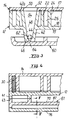
- Fig. 1
- einen Querschnitt durch eine Transportpalette nach der Linie I-I in Fig. 2,
- Fig. 2
- einen Schnitt nach der Linie II-II in Fig. 1, wobei die rechte und die linke Seite zwei unterunterschiedliche Ausführungsformen des Randbereichs zeigen,
- Fig. 3
- einen der Fig. 1 entsprechenden Querschnitt in einem mit einem Fuß versehenen Randbereich der Palette,
- Fig. 4
- einen Querschnitt ähnlich Fig. 3 durch eine andere Ausführungsform der Palette mit fest angebrachten Kufen,
- Fig. 5
- einen Querschnitt nach der Linie V-V in Fig. 4 und
- Fig. 6
- einen Querschnitt durch eine Kufe ähnlich Fig. 5 bei einer Variante mit spreizdübelartiger Kufenbefestigung.
Claims (13)
- Aus Kunststoff gefertigte Transportpalette (10) mit zwei ihre Oberseite (16a) bzw. ihre Unterseite (16) bildenden parallelen Oberflächen, wobeijede Oberfläche (16,16a) die Außenseite der Basis (15,17) jeweils eines von zwei dauerhaft miteinander verbundenen Grundkörpern (12,14) ist, deren Basen (15,17) mit Abstand voneinander angeordnet sind,die Basis (15,17) jedes Grundkörpers (12,14) eine geschlossene Platte ist,der Zwischenraum zwischen den Basen (15,17) der Grundkörper (12,14) durch wenigstens eine Gruppe von Paaren von zwischen sich eine Nut (26) einschließenden Leisten (20,22; 22,24; 24,20) überbrückt wird, wobei alle leisten zueinander parallel angeordnet sindan beiden Enden eines jeden Leistenpaares (20,22; 22,24; 24,20) die Nut (26) jeweils durch einen beide Basen (15,17) verbindenden Quersteg (28) zu einer sich über die gesamte Breite der Palette erstreckenden Kammer geschlossen ist,die Leisten (20,22; 22,24; 24,20) und Querstege (28) einstückig an beiden Basen (15,17) angeformt sind, unddie beiden Grundkörper (12,14) im Bereich der Leisten (20,22,24) und Querstege (28) miteinander dicht verschweißt sind,
dadurch gekennzeichnet,daß der Raum zwischen den Basen (15,17) längs des Umfangs der Palette (10) durch Randleisten (20) geschlossen ist,daß die Palette mit über eine Oberfläche nach außen vorstehenden Füßen (40) versehen ist, wobei die geschlossenen Platten im Bereich der Füße Durchbrechungen aufweisen können, um ein Ineinanderstapeln mehrerer Paletten zu ermöglichen,daß zumindest in eine Nut (26) eine starre Verstärkungseinlage (30) eingelegt ist, unddaß die an beiden Grundkörpern (12,14) der Palette (10) angeformten Leisten (22,24; 22a, 24a), Querstege (28;28a) und Randleisten (20;20a) einander deckungsgleich zugeordnet sind,wobei die Höhe der Leisten (22,24), Querstege (28) und Randleisten (20) des einen Grundkörpers (12) annähernd dem Abstand der Basen (15,17) der beiden die Palette (10) bildenden Grundkörper (12,14) entspricht,während die Höhe der Leisten (22a,24a), Querstege (28a) und Randleisten (20a) des anderen Grundkörpers (14) auf die Höhe von Schweißansätzen beschränkt ist. - Palette nach Anspruch 1, dadurch gekennzeichnet, daß der die Leisten (22a, 24a), Querstege (28a) und Randleisten (20a) mit der Höhe etwa des Basisabstandes der Grundkörper (12, 14) tragende Grundkörper (12) mit den Füßen (40) versehen ist.
- Palette nach Anspruch 1 oder 2, dadurch gekennzeichnet, daß sie zwei Gruppen von Paaren zueinander paralleler Leisten umfaßt, wobei die Richtung der Leisten (22, 24) der einen Gruppe die Richtung der Leisten (22', 24') der anderen Gruppe schneidet, und daß im Schnittbereich eines jeden Leistenpaares der einen Gruppe mit einem Leistenpaar der anderen Gruppe die Leisten derart unterbrochen sind, daß die von allen Leistenpaaren eingeschlossenen Nuten (26; 26') miteinander in Verbindung stehen.
- Palette nach Anspruch 3, dadurch gekennzeichnet, daß eine gitterartige, starre Verstärkungseinlage in die Nuten eingelegt ist.
- Palette nach Anspruch 3 oder 4, dadurch gekennzeichnet, daß zumindest die Leisten einer Gruppe parallel zu einem Rand der Palette (10) verlaufen.
- Palette nach einem der vorhergehenden Ansprüche, dadurch gekennzeichnet, daß die Füße (40) als Hohlkörper ausgebildet und in einem von den Leistenpaaren (22, 24; 22', 24') freigehaltenen Bereich angeordnet sind, daß sich ihr Querschnitt in Richtung auf ihr freies Ende stetig verjüngt, daß die von den Füßen abgewandte Oberfläche (16a) der Palette (10) jedem der Füße (40) gegenüberliegend eine zum Einsetzen eines Fußes (40) geeignete Durchbrechung (52) aufweist, daß sich der von den Füßen umschlossene Hohlraum (54) in Richtung auf diese Durchbrechung (52) öffnet und daß der Bereich zwischen der Durchbrechung (52) und dem den Fuß (40) tragenden Grundkörper (12) mit einer an beide Basen (15, 17) dicht anschließenden Wandung umschlossen ist, deren innere Wandfläche (50) fluchtend in die innere Wandfläche (44) des Fußes (40) übergeht.
- Palette nach einem der vorhergehenden Ansprüche, dadurch gekennzeichnet, daß die freien Enden (46) der Füße (40) und auf den durch jeweils eine Kufe zu überbrückenden Abstand zweier Füße (40) abgestimmte Kufen (60, 61) mit einander zugeordneten Verbindungselementen (64, 62) derart versehen sind, daß die Palette (10) unterhalb der Füße (40) mit wenigstens zwei zueinander parallelen Kufen (60, 61) versehbar ist.
- Palette nach Anspruch 7, dadurch gekennzeichnet, daß die Kufen (61) aus einem mit den Füßen (40) verbundenen, nach unten geöffneten, wannenartigen Oberteil (70) und einem dessen Öffnung abdeckenden und mit diesem zur Bildung eines Hohlkörpers dicht verbundenen Unterteil (76) bestehen.
- Palette nach Anspruch 8, dadurch gekennzeichnet, daß das Oberteil (70) an seinen den Füßen (40) zugewandten Längskanten (72) abgeschrägt ist.
- Palette nach einem der Ansprüche 8 oder 9, dadurch gekennzeichnet, daß die Kufen (61) durch am Oberteil (70) ausgebildete Längsrippen (74) in Kammern unterteilt sind.
- Palette nach einem der Ansprüche 8 bis 10, dadurch gekennzeichnet, daß das Unterteil (76) als flacher Deckel ausgebildet ist, der den Rändern des Oberteils (70) und gegebenenfalls dessen Längsrippen (74) zugeordnete Schweißansätze (78, 80) aufweist.
- Palette nach einemd er Ansprüche 10 oder 11, dadurch gekennzeichnet, daß zumindest eine der Kufenkammern eine starre Verstärkungseinlage enthält.
- Palette nach einem der Ansprüche 8 bis 12, dadurch gekennzeichnet, daß die Füße (40) als nach unten offene Rahmen (41) an der Unterseite (16) der Palette (10) angeformt sind, denen an den Kufen (60) jeeils entsprechend geformte Rahmen (43) zugeordnet sind, und daß die einander zugeordneten Rahmen an der Unterseite (16) und an den Kufen (61) unter Bildung jeweils eines dichten Hohlraums miteinander verschweißt sind.
Applications Claiming Priority (3)
| Application Number | Priority Date | Filing Date | Title |
|---|---|---|---|
| DE4237917A DE4237917C2 (de) | 1992-11-10 | 1992-11-10 | Aus Kunststoff gepreßte Transportpalette |
| DE4237917 | 1992-11-10 | ||
| PCT/EP1993/003149 WO1994011262A1 (de) | 1992-11-10 | 1993-11-10 | Aus kunststoff gefertigte transportpalette |
Publications (3)
| Publication Number | Publication Date |
|---|---|
| EP0619796A1 EP0619796A1 (de) | 1994-10-19 |
| EP0619796B1 EP0619796B1 (de) | 1996-07-24 |
| EP0619796B2 true EP0619796B2 (de) | 1999-09-08 |
Family
ID=6472524
Family Applications (1)
| Application Number | Title | Priority Date | Filing Date |
|---|---|---|---|
| EP94901790A Expired - Lifetime EP0619796B2 (de) | 1992-11-10 | 1993-11-10 | Aus kunststoff gefertigte transportpalette |
Country Status (10)
| Country | Link |
|---|---|
| US (1) | US5806436A (de) |
| EP (1) | EP0619796B2 (de) |
| JP (1) | JP2904309B2 (de) |
| AT (1) | ATE140669T1 (de) |
| DE (2) | DE4237917C2 (de) |
| DK (1) | DK0619796T4 (de) |
| ES (1) | ES2091685T5 (de) |
| GR (2) | GR3021090T3 (de) |
| RU (1) | RU2126349C1 (de) |
| WO (1) | WO1994011262A1 (de) |
Families Citing this family (39)
| Publication number | Priority date | Publication date | Assignee | Title |
|---|---|---|---|---|
| DE9415328U1 (de) * | 1993-09-24 | 1994-11-24 | Stegmaier, Peter, 73630 Remshalden | Palette |
| SE501539C2 (sv) * | 1994-04-13 | 1995-03-06 | Perstorp Ab | Hålrumsmede till lastpall i plast |
| NO306205B1 (no) * | 1996-01-11 | 1999-10-04 | Borealis As | Plastpall |
| US6250234B1 (en) | 1998-07-01 | 2001-06-26 | Rehrig Pacific Company | Method of reinforcing a plastic pallet |
| US6283044B1 (en) * | 1998-07-01 | 2001-09-04 | Rehrig Pacific Company | Pallet assembly |
| NL1014120C2 (nl) * | 2000-01-19 | 2001-07-20 | Lankhorst Recycling Bv | Rolvlonder. |
| US6718888B2 (en) * | 2000-04-11 | 2004-04-13 | Nextreme, Llc | Thermoformed platform |
| US8077040B2 (en) | 2000-01-24 | 2011-12-13 | Nextreme, Llc | RF-enabled pallet |
| US7342496B2 (en) | 2000-01-24 | 2008-03-11 | Nextreme Llc | RF-enabled pallet |
| US7874256B2 (en) * | 2000-04-11 | 2011-01-25 | Nextreme, Llc | Fire resistant plastic pallet with low radio frequency resistivity |
| US8347794B2 (en) | 2000-04-11 | 2013-01-08 | Nextreme, Llc | Fire resistant pallet |
| US6651815B1 (en) * | 2000-05-22 | 2003-11-25 | Rehrig Pacific Company | Top frame assembly |
| US6748876B2 (en) | 2001-10-30 | 2004-06-15 | Patent Holding Company | Reinforced composite pallet assembly of the sandwich-type with a locally crushed cellular core |
| US6655299B2 (en) | 2001-10-30 | 2003-12-02 | Patent Holding Company | Reinforced composite pallet assembly of the cellular core sandwich-type |
| US6823803B2 (en) | 2001-10-30 | 2004-11-30 | Patent Holding Company | Assembly for enclosing and protecting a plurality of meters for storage or transportation purposes and carrier and pallet for use therein |
| US6874428B2 (en) * | 2001-12-18 | 2005-04-05 | Rehrig Pacific Company | Plastic pallet |
| USD476789S1 (en) | 2001-12-18 | 2003-07-01 | Rehrig Pacific Company | Pallet |
| US20040025757A1 (en) * | 2002-05-08 | 2004-02-12 | Fan Jerry J. | Top frame |
| US20030233963A1 (en) * | 2002-05-17 | 2003-12-25 | Fan Jerry J. | Central pallet connector or post for use with grabber arms of a forklift |
| RU2222482C1 (ru) * | 2002-07-01 | 2004-01-27 | Общество с ограниченной ответственностью "Компания СИС" | Поддон из термопластичного материала |
| US20040134390A1 (en) * | 2003-01-09 | 2004-07-15 | Rehrig Pacific Company | Nestable pallet |
| US7640867B2 (en) * | 2003-04-28 | 2010-01-05 | Rehrig Pacific Company | Pallet assembly |
| US7661373B2 (en) * | 2003-04-28 | 2010-02-16 | Rehrig Pacific Company | Pallet assembly |
| US7086339B2 (en) * | 2003-04-29 | 2006-08-08 | Rehrig Pacific Company | Pallet assembly |
| DE102005013933B4 (de) * | 2005-03-26 | 2007-05-24 | Daimlerchrysler Ag | Werkstückträger zum Transport von Aggregaten |
| AU2006203742A1 (en) * | 2005-09-09 | 2007-03-29 | Rehrig Pacific Company | Pallet |
| US7644666B2 (en) | 2006-02-09 | 2010-01-12 | Rehrig Pacific Company | Pallet |
| US7690315B2 (en) | 2007-06-15 | 2010-04-06 | Rehrig Pacific Company | Nestable pallet |
| EP2197768B1 (de) * | 2007-09-14 | 2013-01-23 | FlexLink Components AB | Palette und palettensystem |
| US9988180B2 (en) * | 2008-01-18 | 2018-06-05 | Rehrig Pacific Company | Pallet |
| JP2014169100A (ja) * | 2013-03-04 | 2014-09-18 | Sanko Co Ltd | ボックスパレット |
| AU2017201039B2 (en) | 2016-02-16 | 2022-08-04 | Rehrig Pacific Company | Lift and pallet |
| US10479553B2 (en) | 2016-02-26 | 2019-11-19 | Rehrig Pacific Company | Nestable pallet |
| US10661944B2 (en) | 2016-10-11 | 2020-05-26 | Rehrig Pacific Company | Pallet with inset deck |
| US11352169B2 (en) | 2019-01-18 | 2022-06-07 | Rehrig Pacific Company | Pallet assembly |
| US11174070B2 (en) | 2019-08-07 | 2021-11-16 | Rehrig Pacific Company | Stackable pallet |
| US11034371B2 (en) | 2019-08-19 | 2021-06-15 | Rehrig Pacific Company | Pallet sled |
| USD895224S1 (en) | 2020-05-20 | 2020-09-01 | Rehrig Pacific Company | Pallet |
| USD895223S1 (en) | 2020-05-20 | 2020-09-01 | Rehrig Pacific Company | Pallet |
Citations (7)
| Publication number | Priority date | Publication date | Assignee | Title |
|---|---|---|---|---|
| US3709161A (en) † | 1971-04-06 | 1973-01-09 | Narad Inc | Honeycomb pallet |
| GB1325017A (en) † | 1969-10-22 | 1973-08-01 | Seisan Nipponsha Kk | Process and appa'atus for making ribbed synthetic resin boards |
| US3938448A (en) † | 1970-12-30 | 1976-02-17 | Mitsubishi Chemical Industries Ltd. | Plastic pallet |
| FR2389485A1 (en) † | 1977-05-03 | 1978-12-01 | Proplan Sa | Adhesive backed laminated film with integral air pockets - for use as impact resistant masking tape |
| WO1983001243A1 (en) † | 1981-10-05 | 1983-04-14 | Odljung, Roland | Loading pallet |
| EP0298973A1 (de) † | 1986-03-14 | 1989-01-18 | Ulf Melin | Paneel mit zellenstruktur. |
| SE463761B (sv) † | 1989-01-24 | 1991-01-21 | Carin Melin | Foerfarande foer framstaellning av en platta till en lastpall |
Family Cites Families (12)
| Publication number | Priority date | Publication date | Assignee | Title |
|---|---|---|---|---|
| US3702100A (en) * | 1971-04-05 | 1972-11-07 | Menasha Corp | Molded pallet |
| FR2206248B3 (de) * | 1972-11-10 | 1975-11-28 | Gmt Sa | |
| DE7305667U (de) * | 1973-02-15 | 1973-10-25 | Huels Chemische Werke Ag | Stapelplatte |
| GB1571190A (en) * | 1975-12-09 | 1980-07-09 | Wavin Bv | Pallets |
| JPS5319577U (de) * | 1976-07-29 | 1978-02-20 | ||
| DE2731131C2 (de) * | 1977-07-09 | 1986-01-09 | Werzalit-Werke J.F. Werz KG, 7141 Oberstenfeld | Flachpalette |
| US4397247A (en) * | 1980-01-03 | 1983-08-09 | Lemelson Jerome H | Molding system and article |
| DE8535530U1 (de) * | 1985-12-18 | 1986-07-17 | Remaplan GmbH, 8000 München | Palette aus Kunststoff |
| DE8626847U1 (de) * | 1986-10-09 | 1988-02-11 | Verlinden, Marius A. J., Antwerpen | Kunststoffpalette |
| US4879956A (en) * | 1988-01-14 | 1989-11-14 | Shuert Lyle H | Plastic pallet |
| US5117762A (en) * | 1990-02-26 | 1992-06-02 | Shuert Lyle H | Rackable plastic pallet |
| FR2702450B1 (fr) * | 1993-03-10 | 1995-04-21 | Guy Hamard | Support plat recyclable pour transporter des marchandises, notamment palette. |
-
1992
- 1992-11-10 DE DE4237917A patent/DE4237917C2/de not_active Expired - Fee Related
-
1993
- 1993-11-10 RU RU94037234A patent/RU2126349C1/ru active
- 1993-11-10 ES ES94901790T patent/ES2091685T5/es not_active Expired - Lifetime
- 1993-11-10 WO PCT/EP1993/003149 patent/WO1994011262A1/de not_active Ceased
- 1993-11-10 EP EP94901790A patent/EP0619796B2/de not_active Expired - Lifetime
- 1993-11-10 AT AT94901790T patent/ATE140669T1/de not_active IP Right Cessation
- 1993-11-10 JP JP6511705A patent/JP2904309B2/ja not_active Expired - Fee Related
- 1993-11-10 DE DE59303325T patent/DE59303325D1/de not_active Expired - Lifetime
- 1993-11-10 DK DK94901790T patent/DK0619796T4/da active
-
1996
- 1996-09-19 GR GR960402450T patent/GR3021090T3/el unknown
-
1997
- 1997-11-21 US US08/975,875 patent/US5806436A/en not_active Expired - Fee Related
-
1999
- 1999-11-25 GR GR990403052T patent/GR3031959T3/el unknown
Patent Citations (7)
| Publication number | Priority date | Publication date | Assignee | Title |
|---|---|---|---|---|
| GB1325017A (en) † | 1969-10-22 | 1973-08-01 | Seisan Nipponsha Kk | Process and appa'atus for making ribbed synthetic resin boards |
| US3938448A (en) † | 1970-12-30 | 1976-02-17 | Mitsubishi Chemical Industries Ltd. | Plastic pallet |
| US3709161A (en) † | 1971-04-06 | 1973-01-09 | Narad Inc | Honeycomb pallet |
| FR2389485A1 (en) † | 1977-05-03 | 1978-12-01 | Proplan Sa | Adhesive backed laminated film with integral air pockets - for use as impact resistant masking tape |
| WO1983001243A1 (en) † | 1981-10-05 | 1983-04-14 | Odljung, Roland | Loading pallet |
| EP0298973A1 (de) † | 1986-03-14 | 1989-01-18 | Ulf Melin | Paneel mit zellenstruktur. |
| SE463761B (sv) † | 1989-01-24 | 1991-01-21 | Carin Melin | Foerfarande foer framstaellning av en platta till en lastpall |
Also Published As
| Publication number | Publication date |
|---|---|
| EP0619796B1 (de) | 1996-07-24 |
| DE4237917C2 (de) | 1998-04-16 |
| WO1994011262A1 (de) | 1994-05-26 |
| EP0619796A1 (de) | 1994-10-19 |
| DK0619796T3 (da) | 1996-11-25 |
| DE4237917A1 (de) | 1994-05-11 |
| DK0619796T4 (da) | 2000-02-07 |
| DE59303325D1 (de) | 1996-08-29 |
| JP2904309B2 (ja) | 1999-06-14 |
| ES2091685T3 (es) | 1996-11-01 |
| GR3021090T3 (en) | 1996-12-31 |
| GR3031959T3 (en) | 2000-03-31 |
| ATE140669T1 (de) | 1996-08-15 |
| US5806436A (en) | 1998-09-15 |
| RU94037234A (ru) | 1996-07-20 |
| ES2091685T5 (es) | 2000-01-01 |
| JPH07506796A (ja) | 1995-07-27 |
| RU2126349C1 (ru) | 1999-02-20 |
Similar Documents
| Publication | Publication Date | Title |
|---|---|---|
| EP0619796B2 (de) | Aus kunststoff gefertigte transportpalette | |
| DE69836350T2 (de) | Kunststoff-palette | |
| DE69832087T2 (de) | Kunststoffpalette und verfahren zum herstellen solcher paletten sowie anderer kunststoffprodukte | |
| DE2554210C2 (de) | Doppeldeckpalette aus Kunststoff | |
| DE69403778T2 (de) | Palette | |
| EP0919483B1 (de) | Kunststoffpalette | |
| DE69311263T2 (de) | Kunststoffpalette | |
| DE69806953T2 (de) | Verstärkte kunststoffpalette | |
| DE4336469B4 (de) | Palette | |
| DE2655593A1 (de) | Kunststoffpalette | |
| EP0584133B1 (de) | Kunststoff-palette | |
| DE2403374A1 (de) | Kunststoffpalette | |
| EP2358603B1 (de) | Kunststoffpalette | |
| DE19522000C2 (de) | Kunststoffpalette | |
| EP0227033A2 (de) | Palette aus Kunststoff | |
| WO1994010051A1 (de) | Kunststoff-palette | |
| DE69702744T2 (de) | Trägerelement, wie Palette | |
| DE102020129174A1 (de) | Palettenbasis, Intermediate Bulk Container, Verfahren zum Zusammenbau eines Intermediate Bulk Container, Kufe und Deckstruktur | |
| DE2507275A1 (de) | Flachpalette aus kunststoff | |
| DE2064131B2 (de) | Doppeldeck- Flachpalette aus Kunststoff | |
| DE102007020277A1 (de) | Mehrteilige Palette | |
| DE4026752C2 (de) | Bodenbelag aus plattenförmigen Kunststofformkörpern | |
| DE29902790U1 (de) | Kunststoffpalette | |
| DE9207382U1 (de) | Kunststoff-Palette | |
| EP0404019B1 (de) | Zusammengesetzte Kunststoffpalette |
Legal Events
| Date | Code | Title | Description |
|---|---|---|---|
| PUAI | Public reference made under article 153(3) epc to a published international application that has entered the european phase |
Free format text: ORIGINAL CODE: 0009012 |
|
| AK | Designated contracting states |
Kind code of ref document: A1 Designated state(s): AT BE DE DK ES FR GB GR IT NL PT SE |
|
| 17P | Request for examination filed |
Effective date: 19941022 |
|
| 17Q | First examination report despatched |
Effective date: 19950728 |
|
| GRAG | Despatch of communication of intention to grant |
Free format text: ORIGINAL CODE: EPIDOS AGRA |
|
| GRAH | Despatch of communication of intention to grant a patent |
Free format text: ORIGINAL CODE: EPIDOS IGRA |
|
| GRAH | Despatch of communication of intention to grant a patent |
Free format text: ORIGINAL CODE: EPIDOS IGRA |
|
| GRAA | (expected) grant |
Free format text: ORIGINAL CODE: 0009210 |
|
| AK | Designated contracting states |
Kind code of ref document: B1 Designated state(s): AT BE DE DK ES FR GB GR IT NL PT SE |
|
| REF | Corresponds to: |
Ref document number: 140669 Country of ref document: AT Date of ref document: 19960815 Kind code of ref document: T |
|
| REF | Corresponds to: |
Ref document number: 59303325 Country of ref document: DE Date of ref document: 19960829 |
|
| ITF | It: translation for a ep patent filed | ||
| ET | Fr: translation filed | ||
| ET | Fr: translation filed | ||
| GBT | Gb: translation of ep patent filed (gb section 77(6)(a)/1977) |
Effective date: 19961003 |
|
| REG | Reference to a national code |
Ref country code: ES Ref legal event code: FG2A Ref document number: 2091685 Country of ref document: ES Kind code of ref document: T3 |
|
| REG | Reference to a national code |
Ref country code: DK Ref legal event code: T3 |
|
| REG | Reference to a national code |
Ref country code: GR Ref legal event code: FG4A Free format text: 3021090 |
|
| REG | Reference to a national code |
Ref country code: PT Ref legal event code: SC4A Free format text: AVAILABILITY OF NATIONAL TRANSLATION Effective date: 19961014 |
|
| PLBQ | Unpublished change to opponent data |
Free format text: ORIGINAL CODE: EPIDOS OPPO |
|
| PLBI | Opposition filed |
Free format text: ORIGINAL CODE: 0009260 |
|
| PLBF | Reply of patent proprietor to notice(s) of opposition |
Free format text: ORIGINAL CODE: EPIDOS OBSO |
|
| 26 | Opposition filed |
Opponent name: PERSTORP AB Effective date: 19970418 |
|
| NLR1 | Nl: opposition has been filed with the epo |
Opponent name: PERSTORP AB |
|
| PLBF | Reply of patent proprietor to notice(s) of opposition |
Free format text: ORIGINAL CODE: EPIDOS OBSO |
|
| PLBF | Reply of patent proprietor to notice(s) of opposition |
Free format text: ORIGINAL CODE: EPIDOS OBSO |
|
| PLAW | Interlocutory decision in opposition |
Free format text: ORIGINAL CODE: EPIDOS IDOP |
|
| PLAW | Interlocutory decision in opposition |
Free format text: ORIGINAL CODE: EPIDOS IDOP |
|
| PUAH | Patent maintained in amended form |
Free format text: ORIGINAL CODE: 0009272 |
|
| STAA | Information on the status of an ep patent application or granted ep patent |
Free format text: STATUS: PATENT MAINTAINED AS AMENDED |
|
| 27A | Patent maintained in amended form |
Effective date: 19990908 |
|
| AK | Designated contracting states |
Kind code of ref document: B2 Designated state(s): AT BE DE DK ES FR GB GR IT NL PT SE |
|
| GBTA | Gb: translation of amended ep patent filed (gb section 77(6)(b)/1977) | ||
| PG25 | Lapsed in a contracting state [announced via postgrant information from national office to epo] |
Ref country code: GR Free format text: THE PATENT HAS BEEN ANNULLED BY A DECISION OF A NATIONAL AUTHORITY Effective date: 19991125 |
|
| ITF | It: translation for a ep patent filed | ||
| REG | Reference to a national code |
Ref country code: ES Ref legal event code: DC2A Kind code of ref document: T5 Effective date: 19991122 |
|
| ET3 | Fr: translation filed ** decision concerning opposition | ||
| NLR3 | Nl: receipt of modified translations in the netherlands language after an opposition procedure | ||
| REG | Reference to a national code |
Ref country code: DK Ref legal event code: T4 |
|
| REG | Reference to a national code |
Ref country code: GB Ref legal event code: IF02 |
|
| PGFP | Annual fee paid to national office [announced via postgrant information from national office to epo] |
Ref country code: PT Payment date: 20040527 Year of fee payment: 11 |
|
| PGFP | Annual fee paid to national office [announced via postgrant information from national office to epo] |
Ref country code: GR Payment date: 20040528 Year of fee payment: 11 |
|
| PG25 | Lapsed in a contracting state [announced via postgrant information from national office to epo] |
Ref country code: PT Free format text: LAPSE BECAUSE OF NON-PAYMENT OF DUE FEES Effective date: 20050510 |
|
| REG | Reference to a national code |
Ref country code: PT Ref legal event code: MM4A Effective date: 20050510 |
|
| PGFP | Annual fee paid to national office [announced via postgrant information from national office to epo] |
Ref country code: IT Payment date: 20061130 Year of fee payment: 14 |
|
| PGFP | Annual fee paid to national office [announced via postgrant information from national office to epo] |
Ref country code: SE Payment date: 20070530 Year of fee payment: 14 Ref country code: ES Payment date: 20070530 Year of fee payment: 14 |
|
| PGFP | Annual fee paid to national office [announced via postgrant information from national office to epo] |
Ref country code: DK Payment date: 20070531 Year of fee payment: 14 Ref country code: AT Payment date: 20070531 Year of fee payment: 14 |
|
| PGFP | Annual fee paid to national office [announced via postgrant information from national office to epo] |
Ref country code: GB Payment date: 20070529 Year of fee payment: 14 |
|
| PGFP | Annual fee paid to national office [announced via postgrant information from national office to epo] |
Ref country code: FR Payment date: 20070531 Year of fee payment: 14 |
|
| REG | Reference to a national code |
Ref country code: DK Ref legal event code: EBP |
|
| EUG | Se: european patent has lapsed | ||
| GBPC | Gb: european patent ceased through non-payment of renewal fee |
Effective date: 20071110 |
|
| PG25 | Lapsed in a contracting state [announced via postgrant information from national office to epo] |
Ref country code: AT Free format text: LAPSE BECAUSE OF NON-PAYMENT OF DUE FEES Effective date: 20071110 |
|
| PG25 | Lapsed in a contracting state [announced via postgrant information from national office to epo] |
Ref country code: SE Free format text: LAPSE BECAUSE OF NON-PAYMENT OF DUE FEES Effective date: 20071111 Ref country code: DK Free format text: LAPSE BECAUSE OF NON-PAYMENT OF DUE FEES Effective date: 20071130 |
|
| REG | Reference to a national code |
Ref country code: FR Ref legal event code: ST Effective date: 20080930 |
|
| PG25 | Lapsed in a contracting state [announced via postgrant information from national office to epo] |
Ref country code: GB Free format text: LAPSE BECAUSE OF NON-PAYMENT OF DUE FEES Effective date: 20071110 |
|
| PGFP | Annual fee paid to national office [announced via postgrant information from national office to epo] |
Ref country code: NL Payment date: 20081130 Year of fee payment: 16 |
|
| REG | Reference to a national code |
Ref country code: ES Ref legal event code: FD2A Effective date: 20071112 |
|
| PGFP | Annual fee paid to national office [announced via postgrant information from national office to epo] |
Ref country code: BE Payment date: 20081201 Year of fee payment: 16 |
|
| PG25 | Lapsed in a contracting state [announced via postgrant information from national office to epo] |
Ref country code: FR Free format text: LAPSE BECAUSE OF NON-PAYMENT OF DUE FEES Effective date: 20071130 Ref country code: ES Free format text: LAPSE BECAUSE OF NON-PAYMENT OF DUE FEES Effective date: 20071112 |
|
| PG25 | Lapsed in a contracting state [announced via postgrant information from national office to epo] |
Ref country code: IT Free format text: LAPSE BECAUSE OF NON-PAYMENT OF DUE FEES Effective date: 20071110 |
|
| PG25 | Lapsed in a contracting state [announced via postgrant information from national office to epo] |
Ref country code: DE Free format text: LAPSE BECAUSE OF NON-PAYMENT OF DUE FEES Effective date: 20090603 |
|
| BERE | Be: lapsed |
Owner name: *ERTL FRANZ XAVER Effective date: 20091130 |
|
| REG | Reference to a national code |
Ref country code: NL Ref legal event code: V1 Effective date: 20100601 |
|
| PGFP | Annual fee paid to national office [announced via postgrant information from national office to epo] |
Ref country code: DE Payment date: 20100120 Year of fee payment: 17 |
|
| PG25 | Lapsed in a contracting state [announced via postgrant information from national office to epo] |
Ref country code: NL Free format text: LAPSE BECAUSE OF NON-PAYMENT OF DUE FEES Effective date: 20100601 Ref country code: BE Free format text: LAPSE BECAUSE OF NON-PAYMENT OF DUE FEES Effective date: 20091130 |
|
| REG | Reference to a national code |
Ref country code: DE Ref legal event code: R119 Ref document number: 59303325 Country of ref document: DE Effective date: 20110601 Ref country code: DE Ref legal event code: R119 Ref document number: 59303325 Country of ref document: DE Effective date: 20110531 |
|
| PG25 | Lapsed in a contracting state [announced via postgrant information from national office to epo] |
Ref country code: DE Free format text: LAPSE BECAUSE OF NON-PAYMENT OF DUE FEES Effective date: 20110531 |