EP0618572A2 - Support d'enregistrement magnéto-optique sur lequel il est possible d'enregistrer des informations en haute densité et procédé de reproduction des informations enrégistrées - Google Patents
Support d'enregistrement magnéto-optique sur lequel il est possible d'enregistrer des informations en haute densité et procédé de reproduction des informations enrégistrées Download PDFInfo
- Publication number
- EP0618572A2 EP0618572A2 EP94302309A EP94302309A EP0618572A2 EP 0618572 A2 EP0618572 A2 EP 0618572A2 EP 94302309 A EP94302309 A EP 94302309A EP 94302309 A EP94302309 A EP 94302309A EP 0618572 A2 EP0618572 A2 EP 0618572A2
- Authority
- EP
- European Patent Office
- Prior art keywords
- magnetic layer
- layer
- magnetic
- temperature
- reproducing
- Prior art date
- Legal status (The legal status is an assumption and is not a legal conclusion. Google has not performed a legal analysis and makes no representation as to the accuracy of the status listed.)
- Granted
Links
Images


Classifications
-
- G—PHYSICS
- G11—INFORMATION STORAGE
- G11B—INFORMATION STORAGE BASED ON RELATIVE MOVEMENT BETWEEN RECORD CARRIER AND TRANSDUCER
- G11B11/00—Recording on or reproducing from the same record carrier wherein for these two operations the methods are covered by different main groups of groups G11B3/00 - G11B7/00 or by different subgroups of group G11B9/00; Record carriers therefor
- G11B11/10—Recording on or reproducing from the same record carrier wherein for these two operations the methods are covered by different main groups of groups G11B3/00 - G11B7/00 or by different subgroups of group G11B9/00; Record carriers therefor using recording by magnetic means or other means for magnetisation or demagnetisation of a record carrier, e.g. light induced spin magnetisation; Demagnetisation by thermal or stress means in the presence or not of an orienting magnetic field
- G11B11/105—Recording on or reproducing from the same record carrier wherein for these two operations the methods are covered by different main groups of groups G11B3/00 - G11B7/00 or by different subgroups of group G11B9/00; Record carriers therefor using recording by magnetic means or other means for magnetisation or demagnetisation of a record carrier, e.g. light induced spin magnetisation; Demagnetisation by thermal or stress means in the presence or not of an orienting magnetic field using a beam of light or a magnetic field for recording by change of magnetisation and a beam of light for reproducing, i.e. magneto-optical, e.g. light-induced thermomagnetic recording, spin magnetisation recording, Kerr or Faraday effect reproducing
- G11B11/10582—Record carriers characterised by the selection of the material or by the structure or form
-
- G—PHYSICS
- G11—INFORMATION STORAGE
- G11B—INFORMATION STORAGE BASED ON RELATIVE MOVEMENT BETWEEN RECORD CARRIER AND TRANSDUCER
- G11B11/00—Recording on or reproducing from the same record carrier wherein for these two operations the methods are covered by different main groups of groups G11B3/00 - G11B7/00 or by different subgroups of group G11B9/00; Record carriers therefor
- G11B11/10—Recording on or reproducing from the same record carrier wherein for these two operations the methods are covered by different main groups of groups G11B3/00 - G11B7/00 or by different subgroups of group G11B9/00; Record carriers therefor using recording by magnetic means or other means for magnetisation or demagnetisation of a record carrier, e.g. light induced spin magnetisation; Demagnetisation by thermal or stress means in the presence or not of an orienting magnetic field
- G11B11/105—Recording on or reproducing from the same record carrier wherein for these two operations the methods are covered by different main groups of groups G11B3/00 - G11B7/00 or by different subgroups of group G11B9/00; Record carriers therefor using recording by magnetic means or other means for magnetisation or demagnetisation of a record carrier, e.g. light induced spin magnetisation; Demagnetisation by thermal or stress means in the presence or not of an orienting magnetic field using a beam of light or a magnetic field for recording by change of magnetisation and a beam of light for reproducing, i.e. magneto-optical, e.g. light-induced thermomagnetic recording, spin magnetisation recording, Kerr or Faraday effect reproducing
- G11B11/10502—Recording on or reproducing from the same record carrier wherein for these two operations the methods are covered by different main groups of groups G11B3/00 - G11B7/00 or by different subgroups of group G11B9/00; Record carriers therefor using recording by magnetic means or other means for magnetisation or demagnetisation of a record carrier, e.g. light induced spin magnetisation; Demagnetisation by thermal or stress means in the presence or not of an orienting magnetic field using a beam of light or a magnetic field for recording by change of magnetisation and a beam of light for reproducing, i.e. magneto-optical, e.g. light-induced thermomagnetic recording, spin magnetisation recording, Kerr or Faraday effect reproducing characterised by the transducing operation to be executed
- G11B11/10504—Recording
- G11B11/10506—Recording by modulating only the light beam of the transducer
-
- G—PHYSICS
- G11—INFORMATION STORAGE
- G11B—INFORMATION STORAGE BASED ON RELATIVE MOVEMENT BETWEEN RECORD CARRIER AND TRANSDUCER
- G11B11/00—Recording on or reproducing from the same record carrier wherein for these two operations the methods are covered by different main groups of groups G11B3/00 - G11B7/00 or by different subgroups of group G11B9/00; Record carriers therefor
- G11B11/10—Recording on or reproducing from the same record carrier wherein for these two operations the methods are covered by different main groups of groups G11B3/00 - G11B7/00 or by different subgroups of group G11B9/00; Record carriers therefor using recording by magnetic means or other means for magnetisation or demagnetisation of a record carrier, e.g. light induced spin magnetisation; Demagnetisation by thermal or stress means in the presence or not of an orienting magnetic field
- G11B11/105—Recording on or reproducing from the same record carrier wherein for these two operations the methods are covered by different main groups of groups G11B3/00 - G11B7/00 or by different subgroups of group G11B9/00; Record carriers therefor using recording by magnetic means or other means for magnetisation or demagnetisation of a record carrier, e.g. light induced spin magnetisation; Demagnetisation by thermal or stress means in the presence or not of an orienting magnetic field using a beam of light or a magnetic field for recording by change of magnetisation and a beam of light for reproducing, i.e. magneto-optical, e.g. light-induced thermomagnetic recording, spin magnetisation recording, Kerr or Faraday effect reproducing
- G11B11/10502—Recording on or reproducing from the same record carrier wherein for these two operations the methods are covered by different main groups of groups G11B3/00 - G11B7/00 or by different subgroups of group G11B9/00; Record carriers therefor using recording by magnetic means or other means for magnetisation or demagnetisation of a record carrier, e.g. light induced spin magnetisation; Demagnetisation by thermal or stress means in the presence or not of an orienting magnetic field using a beam of light or a magnetic field for recording by change of magnetisation and a beam of light for reproducing, i.e. magneto-optical, e.g. light-induced thermomagnetic recording, spin magnetisation recording, Kerr or Faraday effect reproducing characterised by the transducing operation to be executed
- G11B11/10504—Recording
- G11B11/10508—Recording by modulating only the magnetic field at the transducer
-
- G—PHYSICS
- G11—INFORMATION STORAGE
- G11B—INFORMATION STORAGE BASED ON RELATIVE MOVEMENT BETWEEN RECORD CARRIER AND TRANSDUCER
- G11B11/00—Recording on or reproducing from the same record carrier wherein for these two operations the methods are covered by different main groups of groups G11B3/00 - G11B7/00 or by different subgroups of group G11B9/00; Record carriers therefor
- G11B11/10—Recording on or reproducing from the same record carrier wherein for these two operations the methods are covered by different main groups of groups G11B3/00 - G11B7/00 or by different subgroups of group G11B9/00; Record carriers therefor using recording by magnetic means or other means for magnetisation or demagnetisation of a record carrier, e.g. light induced spin magnetisation; Demagnetisation by thermal or stress means in the presence or not of an orienting magnetic field
- G11B11/105—Recording on or reproducing from the same record carrier wherein for these two operations the methods are covered by different main groups of groups G11B3/00 - G11B7/00 or by different subgroups of group G11B9/00; Record carriers therefor using recording by magnetic means or other means for magnetisation or demagnetisation of a record carrier, e.g. light induced spin magnetisation; Demagnetisation by thermal or stress means in the presence or not of an orienting magnetic field using a beam of light or a magnetic field for recording by change of magnetisation and a beam of light for reproducing, i.e. magneto-optical, e.g. light-induced thermomagnetic recording, spin magnetisation recording, Kerr or Faraday effect reproducing
- G11B11/10502—Recording on or reproducing from the same record carrier wherein for these two operations the methods are covered by different main groups of groups G11B3/00 - G11B7/00 or by different subgroups of group G11B9/00; Record carriers therefor using recording by magnetic means or other means for magnetisation or demagnetisation of a record carrier, e.g. light induced spin magnetisation; Demagnetisation by thermal or stress means in the presence or not of an orienting magnetic field using a beam of light or a magnetic field for recording by change of magnetisation and a beam of light for reproducing, i.e. magneto-optical, e.g. light-induced thermomagnetic recording, spin magnetisation recording, Kerr or Faraday effect reproducing characterised by the transducing operation to be executed
- G11B11/10515—Reproducing
-
- G—PHYSICS
- G11—INFORMATION STORAGE
- G11B—INFORMATION STORAGE BASED ON RELATIVE MOVEMENT BETWEEN RECORD CARRIER AND TRANSDUCER
- G11B11/00—Recording on or reproducing from the same record carrier wherein for these two operations the methods are covered by different main groups of groups G11B3/00 - G11B7/00 or by different subgroups of group G11B9/00; Record carriers therefor
- G11B11/10—Recording on or reproducing from the same record carrier wherein for these two operations the methods are covered by different main groups of groups G11B3/00 - G11B7/00 or by different subgroups of group G11B9/00; Record carriers therefor using recording by magnetic means or other means for magnetisation or demagnetisation of a record carrier, e.g. light induced spin magnetisation; Demagnetisation by thermal or stress means in the presence or not of an orienting magnetic field
- G11B11/105—Recording on or reproducing from the same record carrier wherein for these two operations the methods are covered by different main groups of groups G11B3/00 - G11B7/00 or by different subgroups of group G11B9/00; Record carriers therefor using recording by magnetic means or other means for magnetisation or demagnetisation of a record carrier, e.g. light induced spin magnetisation; Demagnetisation by thermal or stress means in the presence or not of an orienting magnetic field using a beam of light or a magnetic field for recording by change of magnetisation and a beam of light for reproducing, i.e. magneto-optical, e.g. light-induced thermomagnetic recording, spin magnetisation recording, Kerr or Faraday effect reproducing
- G11B11/10502—Recording on or reproducing from the same record carrier wherein for these two operations the methods are covered by different main groups of groups G11B3/00 - G11B7/00 or by different subgroups of group G11B9/00; Record carriers therefor using recording by magnetic means or other means for magnetisation or demagnetisation of a record carrier, e.g. light induced spin magnetisation; Demagnetisation by thermal or stress means in the presence or not of an orienting magnetic field using a beam of light or a magnetic field for recording by change of magnetisation and a beam of light for reproducing, i.e. magneto-optical, e.g. light-induced thermomagnetic recording, spin magnetisation recording, Kerr or Faraday effect reproducing characterised by the transducing operation to be executed
- G11B11/10528—Shaping of magnetic domains, e.g. form, dimensions
-
- G—PHYSICS
- G11—INFORMATION STORAGE
- G11B—INFORMATION STORAGE BASED ON RELATIVE MOVEMENT BETWEEN RECORD CARRIER AND TRANSDUCER
- G11B11/00—Recording on or reproducing from the same record carrier wherein for these two operations the methods are covered by different main groups of groups G11B3/00 - G11B7/00 or by different subgroups of group G11B9/00; Record carriers therefor
- G11B11/10—Recording on or reproducing from the same record carrier wherein for these two operations the methods are covered by different main groups of groups G11B3/00 - G11B7/00 or by different subgroups of group G11B9/00; Record carriers therefor using recording by magnetic means or other means for magnetisation or demagnetisation of a record carrier, e.g. light induced spin magnetisation; Demagnetisation by thermal or stress means in the presence or not of an orienting magnetic field
- G11B11/105—Recording on or reproducing from the same record carrier wherein for these two operations the methods are covered by different main groups of groups G11B3/00 - G11B7/00 or by different subgroups of group G11B9/00; Record carriers therefor using recording by magnetic means or other means for magnetisation or demagnetisation of a record carrier, e.g. light induced spin magnetisation; Demagnetisation by thermal or stress means in the presence or not of an orienting magnetic field using a beam of light or a magnetic field for recording by change of magnetisation and a beam of light for reproducing, i.e. magneto-optical, e.g. light-induced thermomagnetic recording, spin magnetisation recording, Kerr or Faraday effect reproducing
- G11B11/10532—Heads
- G11B11/10541—Heads for reproducing
- G11B11/10543—Heads for reproducing using optical beam of radiation
-
- G—PHYSICS
- G11—INFORMATION STORAGE
- G11B—INFORMATION STORAGE BASED ON RELATIVE MOVEMENT BETWEEN RECORD CARRIER AND TRANSDUCER
- G11B11/00—Recording on or reproducing from the same record carrier wherein for these two operations the methods are covered by different main groups of groups G11B3/00 - G11B7/00 or by different subgroups of group G11B9/00; Record carriers therefor
- G11B11/10—Recording on or reproducing from the same record carrier wherein for these two operations the methods are covered by different main groups of groups G11B3/00 - G11B7/00 or by different subgroups of group G11B9/00; Record carriers therefor using recording by magnetic means or other means for magnetisation or demagnetisation of a record carrier, e.g. light induced spin magnetisation; Demagnetisation by thermal or stress means in the presence or not of an orienting magnetic field
- G11B11/105—Recording on or reproducing from the same record carrier wherein for these two operations the methods are covered by different main groups of groups G11B3/00 - G11B7/00 or by different subgroups of group G11B9/00; Record carriers therefor using recording by magnetic means or other means for magnetisation or demagnetisation of a record carrier, e.g. light induced spin magnetisation; Demagnetisation by thermal or stress means in the presence or not of an orienting magnetic field using a beam of light or a magnetic field for recording by change of magnetisation and a beam of light for reproducing, i.e. magneto-optical, e.g. light-induced thermomagnetic recording, spin magnetisation recording, Kerr or Faraday effect reproducing
- G11B11/10582—Record carriers characterised by the selection of the material or by the structure or form
- G11B11/10584—Record carriers characterised by the selection of the material or by the structure or form characterised by the form, e.g. comprising mechanical protection elements
-
- G—PHYSICS
- G11—INFORMATION STORAGE
- G11B—INFORMATION STORAGE BASED ON RELATIVE MOVEMENT BETWEEN RECORD CARRIER AND TRANSDUCER
- G11B11/00—Recording on or reproducing from the same record carrier wherein for these two operations the methods are covered by different main groups of groups G11B3/00 - G11B7/00 or by different subgroups of group G11B9/00; Record carriers therefor
- G11B11/10—Recording on or reproducing from the same record carrier wherein for these two operations the methods are covered by different main groups of groups G11B3/00 - G11B7/00 or by different subgroups of group G11B9/00; Record carriers therefor using recording by magnetic means or other means for magnetisation or demagnetisation of a record carrier, e.g. light induced spin magnetisation; Demagnetisation by thermal or stress means in the presence or not of an orienting magnetic field
- G11B11/105—Recording on or reproducing from the same record carrier wherein for these two operations the methods are covered by different main groups of groups G11B3/00 - G11B7/00 or by different subgroups of group G11B9/00; Record carriers therefor using recording by magnetic means or other means for magnetisation or demagnetisation of a record carrier, e.g. light induced spin magnetisation; Demagnetisation by thermal or stress means in the presence or not of an orienting magnetic field using a beam of light or a magnetic field for recording by change of magnetisation and a beam of light for reproducing, i.e. magneto-optical, e.g. light-induced thermomagnetic recording, spin magnetisation recording, Kerr or Faraday effect reproducing
- G11B11/10582—Record carriers characterised by the selection of the material or by the structure or form
- G11B11/10586—Record carriers characterised by the selection of the material or by the structure or form characterised by the selection of the material
-
- G—PHYSICS
- G11—INFORMATION STORAGE
- G11B—INFORMATION STORAGE BASED ON RELATIVE MOVEMENT BETWEEN RECORD CARRIER AND TRANSDUCER
- G11B11/00—Recording on or reproducing from the same record carrier wherein for these two operations the methods are covered by different main groups of groups G11B3/00 - G11B7/00 or by different subgroups of group G11B9/00; Record carriers therefor
- G11B11/10—Recording on or reproducing from the same record carrier wherein for these two operations the methods are covered by different main groups of groups G11B3/00 - G11B7/00 or by different subgroups of group G11B9/00; Record carriers therefor using recording by magnetic means or other means for magnetisation or demagnetisation of a record carrier, e.g. light induced spin magnetisation; Demagnetisation by thermal or stress means in the presence or not of an orienting magnetic field
- G11B11/105—Recording on or reproducing from the same record carrier wherein for these two operations the methods are covered by different main groups of groups G11B3/00 - G11B7/00 or by different subgroups of group G11B9/00; Record carriers therefor using recording by magnetic means or other means for magnetisation or demagnetisation of a record carrier, e.g. light induced spin magnetisation; Demagnetisation by thermal or stress means in the presence or not of an orienting magnetic field using a beam of light or a magnetic field for recording by change of magnetisation and a beam of light for reproducing, i.e. magneto-optical, e.g. light-induced thermomagnetic recording, spin magnetisation recording, Kerr or Faraday effect reproducing
- G11B11/10502—Recording on or reproducing from the same record carrier wherein for these two operations the methods are covered by different main groups of groups G11B3/00 - G11B7/00 or by different subgroups of group G11B9/00; Record carriers therefor using recording by magnetic means or other means for magnetisation or demagnetisation of a record carrier, e.g. light induced spin magnetisation; Demagnetisation by thermal or stress means in the presence or not of an orienting magnetic field using a beam of light or a magnetic field for recording by change of magnetisation and a beam of light for reproducing, i.e. magneto-optical, e.g. light-induced thermomagnetic recording, spin magnetisation recording, Kerr or Faraday effect reproducing characterised by the transducing operation to be executed
- G11B11/10504—Recording
-
- G—PHYSICS
- G11—INFORMATION STORAGE
- G11B—INFORMATION STORAGE BASED ON RELATIVE MOVEMENT BETWEEN RECORD CARRIER AND TRANSDUCER
- G11B11/00—Recording on or reproducing from the same record carrier wherein for these two operations the methods are covered by different main groups of groups G11B3/00 - G11B7/00 or by different subgroups of group G11B9/00; Record carriers therefor
- G11B11/10—Recording on or reproducing from the same record carrier wherein for these two operations the methods are covered by different main groups of groups G11B3/00 - G11B7/00 or by different subgroups of group G11B9/00; Record carriers therefor using recording by magnetic means or other means for magnetisation or demagnetisation of a record carrier, e.g. light induced spin magnetisation; Demagnetisation by thermal or stress means in the presence or not of an orienting magnetic field
- G11B11/105—Recording on or reproducing from the same record carrier wherein for these two operations the methods are covered by different main groups of groups G11B3/00 - G11B7/00 or by different subgroups of group G11B9/00; Record carriers therefor using recording by magnetic means or other means for magnetisation or demagnetisation of a record carrier, e.g. light induced spin magnetisation; Demagnetisation by thermal or stress means in the presence or not of an orienting magnetic field using a beam of light or a magnetic field for recording by change of magnetisation and a beam of light for reproducing, i.e. magneto-optical, e.g. light-induced thermomagnetic recording, spin magnetisation recording, Kerr or Faraday effect reproducing
- G11B11/10582—Record carriers characterised by the selection of the material or by the structure or form
- G11B11/10586—Record carriers characterised by the selection of the material or by the structure or form characterised by the selection of the material
- G11B11/10589—Details
- G11B11/10593—Details for improving read-out properties, e.g. polarisation of light
-
- Y—GENERAL TAGGING OF NEW TECHNOLOGICAL DEVELOPMENTS; GENERAL TAGGING OF CROSS-SECTIONAL TECHNOLOGIES SPANNING OVER SEVERAL SECTIONS OF THE IPC; TECHNICAL SUBJECTS COVERED BY FORMER USPC CROSS-REFERENCE ART COLLECTIONS [XRACs] AND DIGESTS
- Y10—TECHNICAL SUBJECTS COVERED BY FORMER USPC
- Y10S—TECHNICAL SUBJECTS COVERED BY FORMER USPC CROSS-REFERENCE ART COLLECTIONS [XRACs] AND DIGESTS
- Y10S428/00—Stock material or miscellaneous articles
- Y10S428/90—Magnetic feature
-
- Y—GENERAL TAGGING OF NEW TECHNOLOGICAL DEVELOPMENTS; GENERAL TAGGING OF CROSS-SECTIONAL TECHNOLOGIES SPANNING OVER SEVERAL SECTIONS OF THE IPC; TECHNICAL SUBJECTS COVERED BY FORMER USPC CROSS-REFERENCE ART COLLECTIONS [XRACs] AND DIGESTS
- Y10—TECHNICAL SUBJECTS COVERED BY FORMER USPC
- Y10T—TECHNICAL SUBJECTS COVERED BY FORMER US CLASSIFICATION
- Y10T428/00—Stock material or miscellaneous articles
- Y10T428/24—Structurally defined web or sheet [e.g., overall dimension, etc.]
- Y10T428/24942—Structurally defined web or sheet [e.g., overall dimension, etc.] including components having same physical characteristic in differing degree
Definitions
- This invention relates to a magnetooptical recording medium for recording/reproducing information using a laser beam utilizing a magnetooptical effect, and more particularly, to a magnetooptical recording medium on which high-density information can be recorded, and a method of reproducing the recorded information.
- magnetooptical recording media In the field of rewritable high-density recording, magnetooptical recording media have attracted notice, in which information is recorded by writing magnetic domains on a magnetic thin film using the thermal energy of a semiconductor laser, and the information is read using a magnetooptical effect. Recently, there has been an increasing demand for large-capacity recording media by increasing the recording density of the magnetooptical recording media.
- the track recording density of an optical disk greatly depends on the wavelength of the laser beam used in the reproducing optical system, and the numerical aperture of the objective lens used in the system. That is, when the wavelength ⁇ of the laser beam used in the reproducing optical system and the numerical aperture N of the objective lens are determined, the diameter of the beam waist is determined. Hence, the detectable limit of the spatial frequency in signal reproduction is about 2NA/ ⁇ .
- the wavelength of the laser beam used in the reproducing optical system must be shortened, and the numerical aperture NA of the objective lens must be increased.
- the wavelength of the laser beam and the numerical aperture of the objective lens Accordingly, techniques have been developed, in which the recording density of a recording medium is increased by improving the configuration of the recording medium and the method of reading information.
- a signal reproducing method in which a signal is recorded in a recording holding layer in a multiple layers comprising a reproducing layer and the recording holding layer magnetically coupled with each other. After aligning the orientation of magnetization in the reproducing layer, the reproducing layer is heated by projecting a laser beam, the signal recorded in the recording holding layer is transferred to the region whose temperature has been raised, and the transferred signal is read.
- the region, whose temperature has been raised to a transfer temperature by being heated by the laser beam and from which a signal is detected, can be limited to a smaller region than the spot size of the reproducing laser beam.
- interference between codes during a reproducing operation is reduced, so that a signal having a period equal to or less than the diffraction limit of light can be reproduced.
- the above-described reproducing method has the problems that, for example, the magnetooptical recording apparatus has a complicated configuration, whereby the cost of the apparatus increases, and the size of the apparatus cannot be reduced.
- the present invention which achieves these objectives relates to a magnetooptical recording medium comprising a first magnetic layer, a second magnetic layer whose Curie temperature is lower than that of the first magnetic layer, and a third magnetic layer, comprising a vertically-magnetizing layer, whose Curie temperature is higher than that of the second magnetic layer.
- the first magnetic layer, the second magnetic layer and the third magnetic layer are in a state of exchange coupling with each other at a portion of a vertically magnetizing film.
- a domain wall formed in the first magnetic layer moves when the temperature of the medium has been raised to at least the Curie temperature of the second magnetic layer.
- the present invention relates to an information reproducing method for reproducing information from a magntooptical recording medium, comprising a first magnetic layer, a second magnetic layer whose Curie temperature is lower than that of the first magnetic layer, and a third magnetic layer, comprising a vertically magnetizing layer, whose Curie temperature is higher than that of the second magnetic layer, the first magnetic layer, the second magnetic layer and the third magnetic layer being in a state of exchange coupling with each other at a portion of a vertically-magnetizing film, and a domain wall formed in the first magnetic layer moving when the temperature of the second magnetic layer has been raised to at least the Curie temperature of the second magnetic layer, the method comprising the steps of rotating the medium, projecting a light beam onto the rotating medium from the side of the first magnetic layer to form a temperature distribution having a gradient in the moving direction of the light beam and having a region of temperatures equal to at least the Curie temperature of the second magnetic layer, and detecting a change in the plane of polarization of reflected light of the
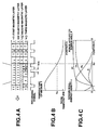
- FIG. 1A is a cross-sectional view illustrating the schematic configuration of a magnetooptical recording medium according to a first embodiment of the present invention.
- the magnetic layer of this medium comprises a first magnetic layer 11, a second magnetic layer 12 and a third magnetic layer 13, which are sequentially laminated.
- Arrow 14 in each layer indicates the direction of an atomic spin.
- a domain wall 15 is formed at the boundary of regions in which the directions of spins are inverse to each other.
- the recording signal for these recording layers is indicated below the cross-section of the medium as a graph.
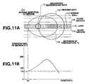
- FIG. 1B is a graph indicating the temperature distribution produced in the magnetooptical recording medium of the first embodiment.
- This temperature distribution may be provided on the medium by a light beam projected for reproducing the recorded signal. It is preferable, however, to provide the temperature distribution using another heating means so that the temperature of the medium is raised from a portion preceding the reproducing light-beam spot in the moving direction of the spot, and a temperature peak is present behind the spot. At position x s , the temperature of the medium reaches temperature T s , which is close to the Curie temperature of the second magnetic layer.
- FIG. 1C is a graph showing the distribution of the domain-wall-energy density ⁇ 1 of the first magnetic layer, which corresponds to the temperature distribution shown in FIG. 1B.
- This force F1 is applied so as to move each domain wall toward a side having lower domain-wall energy, Since the first magnetic layer has a small domain-wall coercive force and a large domain-wall mobility, the domain wall is easily moved by the force F1 if only the first magnetic layer is present. However, since the temperature of the medium is lower than T s at a region preceding position x s (the right side in FIG. 1C), and the first magnetic layer is in a state of exchange coupling with the third magnetic layer having a large domain-wall coercive force, the domain wall in the first magnetic layer is fixed at a position corresponding to the position of the domain wall in the third magnetic layer.
- the domain wall 15 passes under the reproducing light-beam spot 16, all atomic spins in the first magnetic layer within the spot are aligned in one direction. Every time a domain wall 15 reaches the position x s in accordance with the movement of the medium, the domain wall 15 instantaneously moves under the spot, and all atomic spins within the spot are inverted and aligned in one direction.
- the amplitude of the reproduced signal is always constant and has a maximum value irrespective of the recorded interval beween adjacent domain walls (i.e., the recording mark length), and is completely free from problems of waveform interference and the like caused by the optical diffraction limit.
- the time ⁇ required for the domain wall to pass under the spot must not be longer than the time t min required for the medium to move the distance corresponding to the shortest recording mark length (see FIG. 2).
- FIGS. 3A and 3B are schematic diagrams for comparing the information reproducing method of the present invention with a conventional information reproducing method.
- each combination of (a1) through (a7), and (b1) through (b7) indicates a state in which a reproducing spot 31 moves on an information track 36, on which magnetic domains having different recording mark lengths are formed.
- Each of (a8) and (b8) is a graph illustrating the obtained reproduced signal.
- the maximum amplitude of the reproduced signal cannot be obtained (b8) unless the reproducing spot 31 itself completely enters one magnetic domain on the information track 36 (b2).
- the reproducing spot 31 and the temperature profile are subjected to relative movement in the same direction 32, so that the temperature of a portion immediately preceding the reproducing spot 31 equals the critical temperature T s of the second magnetic layer. Accordingly, the temperature of the portion of a domain wall 34 equals the critical temperature T s immediately before the reproducing spot 31 reaches the domain wall 34, so that the domain wall 34 moves in the inverse direction 35, and the reproducing spot 31 completely enters the recorded mark (a2).
- the maximum amplitude of the reproduced signal can be instantaneously obtained (a8).
- the reproducing spot 31 when a magnetic domain 33 is smaller than the spot size, the reproducing spot 31 is not entirely accommodated within the magnetic domain 33 (b3 - b7), and the obtained reproduced signal is not clear (b8).
- the magnetic domain sequentially moves backward in the reverse direction when the reproducing spot 31 substantially reaches the domain wall of the recorded mark (a3 - a7), a very clear reproduced signal is obtained (a8).
- a fourth magnetic layer 44 may be provided between a first magnetic layer 41 and a second magnetic layer 42.
- the Curie temperature of the fourth magnetic layer 44 is higher than that of the second magnetic layer 42, and lower than that of the first magnetic layer 41.
- the fourth magnetic layer 44 comprises a vertically-magnetizing film which has a domain-wall coercive force smaller than that of a third magnetic layer 43 at at least temperatures equal to or higher than the Curie temperature of the second magnetic layer 42.
- the fourth magnetic layer 44 provides a force sufficient to move a domain wall within the first magnetic layer 41.
- FIG. 4C is a graph indicating the distribution of the domain-wall-energy density ⁇ 1 of the first magnetic layer 41 and the domain-wall-energy density ⁇ 4 of the fourth magnetic layer 44, which corresponds to the above-described temperature distribution.
- a force F i is applied to a domain wall in each layer present at position x.
- the force F i moves the domain wall toward a side where the domain-wall energy is low.
- each domain wall In order to read recorded information at a high speed, each domain wall must be moved at a high speed. For that purpose, a large force must be applied to the domain wall.
- the temperature dependency of the domain-wall-energy density increases as the temperature approaches the Curie temperature. Accordingly, the gradient of the domain-wall-energy density in the x direction can be increased by providing a temperature gradient within a temperature range near the Curie temperature, and a large force can be applied to a domain wall.
- the temperature of the medium In order to detect a change in the plane of polarization of reflected light from the first magnetic layer 41, the temperature of the medium must be much lower than the Curie temperature of the first magnetic layer 41 at a region irradiated by the reproducing light-beam spot.
- the fourth magnetic layer 44 having a Curie temperature lower than that of the first magnetic layer 41 is provided adjacent to the first magnetic layer 41 at a side opposite to the side where the light beam is projected, it is possible to provide in the region irradiated by the reproducing light-beam spot a temperature gradient in a temperature range much lower than the Curie temperature of the first magnetic mayer 41, and near the Curie temperature of the fourth magnetic layer 44. As a result, a large force is applied to a domain wall in the fourth magnetic layer 44, and a large force obtained by adding a force caused by the exchange interaction with the fourth magnetic layer 44 is applied to a domain wall in the first magnetic layer 41.
- the fourth magnetic layer 44 can be configured so as to have a temperature immediately below the Curie temperature in the x direction. Hence, a relatively large force can be applied over an entire range in the x direction where domain walls must be moved.
- FIG. 5 is a cross-sectional view illustrating the schematic configuration of layers of a magnetooptical recording medium according to the first embodiment.
- a dielectric layer 55, a first magnetic layer 51, a second magnetic layer 52, a third magnetic layer 53 and a dielectric layer 54 are sequentially laminated on a transparent substrate 56.
- polycarbonate, glass or the like can be used for the transparent substrate 56.
- a transparent dielectric material such as Si3N4, AlN, SiO2, SiO, ZnS, MgF2 or the like, can be used for the dielectric layer 55.
- the same kind of material can be used for the dielectric layer 54, which is finally formed as a protective layer.
- These layers can be deposited, for example, by continuous sputtering using a magnetron sputtering apparatus, continuous vacuum deposition or the like. By continuously forming the respective magnetic layers without breaking vacuum, the respective magnetic layers are in a state of exchange coupling with each other.
- Thermal properties may be adjusted by adding a metallic layer, made of Al, AlTa, AlTi, AlCr, Cu or the like, to this configuration.
- a protective coating made of a polymer resin may also be added to the configuration. Formed layers may be bonded together.
- the magnetic layers 51 - 53 may be made of various kinds of magnetic materials.
- the magnetic layers 51 - 53 may be configured by rare-earth/iron-group amorphous alloys comprising 10 - 40 atomic % of one kind or at least two kinds of rare-earth metallic elements, such as Pr, Nd, Sm, Gd, Tb, Dy, Ho and the like, and 90 - 60 atomic % of one kind or at least two kinds of iron-group elements, such as Fe, Co, Ni and the like.
- a small amount of elements selected from Cr, Mn, Cu, Ti, Al, Si, Pt, In and the like may be added.
- the saturation magnetization of the alloy may be controlled by changing the compositional ratio of rare-earth elements to iron-group elements.
- the Curie temperature of the alloy may also be controlled by changing the compositional ratio.
- the Curie temperature may also be controlled by adjusting the compositional ratio between at least two kinds of rare-earth elements.
- materials such as garnets, platinum-group/iron-group films having a periodic structure, platinum-group/iron-group alloys and the like, may be used.
- a material for bubble memories for example, a rare-earth/iron-group amorphous alloy having small vertical magnetic anisotropy, such as GdCo, GdFeCo, GdFe, NdGdFeCo or the like, or a garnet, is preferred.
- a material having large vertical magnetic anisotropy which can stably hold a magnetized state for example, a rare-earth/iron-group amorphous alloy, such as TbFeCo, DyFeCo, TbDyFeCo or the like, or a platinum-group/iron-group film having a periodic structure, made of Pt/Co, Pd/Co or the like, is preferred.
- a rare-earth/iron-group amorphous alloy such as TbFeCo, DyFeCo, TbDyFeCo or the like
- a platinum-group/iron-group film having a periodic structure made of Pt/Co, Pd/Co or the like
- Recording of a data signal on the magnetooptical recording medium of the present embodiment is performed by modulating an external magnetic field while projecting a laser beam having a power to raise the temperature of the third magnetic layer to at least the Curie temperature onto the moving medium, or by modulating the power of a laser beam while applying a magnetic field in a certain direction.
- a recorded magnetic domain having a size equal to or smaller than the diameter of the laser-beam spot can be formed.
- a signal having a period equal to or less than the diffraction limit of light can be recorded.
- FIG. 6 illustrates the configuration of a medium in which a fourth magnetic layer is added to the above-described configuration.
- a dielectric layer 65, a first magnetic layer 61, a fourth magnetic layer 64, a second magnetic layer 62, a third magnetic layer 63 and a dielectric layer 64 are sequentially laminated on a transparent substrate 66.
- Materials and production methods of the respective layers are the same as those described with reference to FIG. 5.
- Targets made of B-doped Si, Gd, Dy, Tb, Fe and Co were mounted in a DC magnetron sputtering apparatus, a polycarbonate substrate, on which guide grooves for tracking are formed, was fixed on a substrate holder, and the chamber of the apparatus was evacuated by a cryopump until the pressure within the chamber became equal to or less than 1 x 10 ⁇ 5 Pa.
- An Ar gas was introduced within the chamber until the pressure of the chamber became 0.3 Pa while evacuating the chamber.
- An SiN layer, serving as an interference layer, 800 angstrom thick was deposited while rotating the substrate.
- a GdCo layer serving as a first magnetic layer, 300 angstrom thick
- a DyFe layer serving as a second magnetic layer, 100 angstrom thick
- a TbFeCo layer serving as a third magnetic layer, 400 angstrom thick
- an SiN layer serving as a protective layer, 800 angstrom thick was deposited.
- an N2 gas was introduced in addition to the Ar gas, and the layer was deposited by DC reactive sputtering.
- the respective magnetic layers were deposited by applying DC power to the respective targets made of Gd, Dy, Tb, Fe and Co.
- each magnetic layer was adjusted so as to be close to the compensated composition.
- the Curie temperatures of the first magnetic layer, the second magnetic layer and the third magnetic layer were set to be about at least 300 °C, 70 °C and 200 °C, respectively.
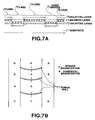
- this medium comprises a dielectric layer 72, a magnetic layer 73 and a dielectric layer 74 laminated on a substrate 71, and concentric circular guide grooves or spiral guide grooves having a rectangular cross section 1000 angstrom deep are formed on the substrate 71. Accordingly, the magnetic layer 73 laminated on lands 76 is substantially separated at portions of guide grooves 75. Actually, the magnetic layer 73 becomes continuous, because a magnetic film is slightly deposited even on step portions. However, since the thickness of the film is much smaller than the thickness of the magnetic layer in other portions, the connection at the step portions can be neglected. In the present invention, a state in which respective information tracks are magnetically separated from each other includes such a state.
- nonclosed domain walls 77 are formed at boundary portions of the magnetic domains on the land 76.
- Such domain walls 77 can be easily moved in the direction of the track, because there is no generation/extinction of domain walls 77 at the sides of the track.
- the effect of magnetically-separated information tracks can be sufficiently obtained even if only the first magnetic layer is magnetically separated instead of magnetically separating all the layers.
- the recording/reproducing apparatus used for the measurement includes the optical system of an ordinay magnetooptical-disk recording/reproducing apparatus, and a laser light source for heating added thereto.
- a laser light source 81 for recording/reproduction has a wavelength of 780 nm, and is disposed so that P-polarized light is incident upon the recording medium.
- a laser light source 82 for heating has a wavelength of 1.3 ⁇ m, and is disposed so that P-polarized light is incident upon the recording medium.
- a dichroic mirror 83 is designed so that light having a wavelength of 780 nm is transmitted by 100 %, and light having a wavelength of 1.3 ⁇ m is reflected by 100 %.
- a polarizing beam splitter 84 is designed so that P-polarized light beams having wavelengths of 780 nm and 1.3 ⁇ m are transmitted by 70 - 80 %, and S-polarized light beams having the same wavelengths are reflected by 100 %.
- the diameter of the light beam having the wavelength of 1.3 ⁇ m is arranged to be smaller than the aperture of an objective lens 85, and to have an NA (numerical aperture) smaller than that of the light beam having the wavelength of 780 nm condensed after passing through the entire aperture.
- a dichroic mirror 87 is provided in order to prevent entrance of the light having the wavelength of 1.3 ⁇ m into a signal detection system, and is designed so as to transmit the light having the wavelength of 780 nm by 100 %, and to reflect the light having the wavelength of 1.3 ⁇ m by 100 %.
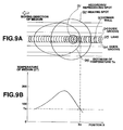
- this optical system can image a recording/reproducing spot 91 and a heating spot 92 on a land 95 between adjacent guide grooves 94 on the recording surface of a recording medium 86. Since the heating spot 92 has a long wavelength and a small NA, its diameter is greater than that of the recording/reproducing spot 91. Hence, it is possible to easily provide a desired temperature gradient as shown in FIG. 9B in the region of the recording/reproducing spot 91 on the recording surface of the moving medium. In FIG. 9A, isotherm 96 of temperature T s is also shown. Recording/reproduction was performed by rotatably driving the medium at a linear velocity of 5 m/sec.
- the modulation frequency of the recording magnetic field was changed between 1 - 10 MHz (megahertz) to record patterns having mark lengths in the range of 2.5 - 0.25 ⁇ m.
- the power of the recording/reproducing laser beam at a reproducing operation was arranged to be 1 mW.
- the C/N ratio was measured for the pattern of each mark length by detecting a change in the plane of polarization of reflected light of the recording/reproducing laser beam while simultaneously projecting the heating laser beam having a power of 20 mW.
- the temperature distribution on the surface of the medium at that time is shown in FIG. 9B. This temperature distribution has a gradient in the moving direction of the recording/reproducing spot 91.
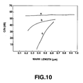
- a graph line "a" shown in FIG. 10 represents the result of the measurement.
- a result of measurement by the conventional ultrahigh-resolution reproducing method described in Japanese Patent Laid-open Application (Kokai) No. 3-93058 (1991) is shown by a graph line b
- a result of measurement by an ordinary reproducing method, in which an ultrahigh resolution phenomenon does not occur is shown by a graph line c.
- the entirety of reversal of magnetization within the reproducing spot can be detected even if the mark length is short, a signal having a period equal to or less than the diffraction limit of light can be reproduced, and the mark-length dependency of the C/N ratio substantially disappears.
- a magnetic-domain pattern was formed in the sample by the same recording method as in the case of first experimental example. The pattern was observed from the film side, i.e., the side of the first magnetic layer, using the polarizing microscope.
- the heating condensed laser beam was projected onto the sample to form substantially the same temperature distribution as in the first experimental sample within the field of view of the polarizing microscope.
- the magnetic-domain pattern preserved in the third magnetic layer was observed to be transferred to the first magnetic layer.
- the domain wall in the first magnetic layer was confirmed to move toward a higher-temperature side caused by the temperature gradient.
- Each magnetooptical recording medium was prepared by forming thin films on a polycarbonate substrate using the same apparatus and method for forming films as in the case of the first experimental example. However, the forming method and the structure of the obtained medium were changed in the following three items.
- an accelerated irradiation processing using Ar ions was performed for the surface of the substrate before forming the films.
- an accelerated irradiation processing using Ar ions was performed for the surface of the film after forming the SiN layer, serving as the interference layer.
- the surface of the obtained medium was smoothed by the above-described processing.
- the thickness of the first magnetic layer was changed to 2000 angstroms. These changed items independently contribute to improvement in the mobility of domain walls of the first magnetic layer.
- Each magnetooptical recording medium was prepared by forming thin films on a polycarbonate substrate using the same apparatus and method for forming films as in the case of the first experimental example.
- a high-power laser beam was projected onto the guide groove portions to anneal the entire magnetic layer at the guide groove portions.
- the property of the magnetic layer at the guide groove portions changed to become a in-plane-magnetizing film, and the coupling between the magnetic layers on adjacent tracks was disconnected. Recording/reproducing characteristics of this medium were measured in the same manner as in the case of the first experimental example, and excellent results as in the case of the first experimental example were obtained.
- patterning may be performed using etching.
- the positional relationship between the recording/reproducing spot and the heating spot was changed as shown in FIG. 11A. That is, the recording/reproducing spot was arranged to be projected onto a portion corresponding to the slope in a front portion in the moving direction of the medium in the temperature distribution provided by the heating laser spot.
- the first magnetic layer and the third magnetic layer are coupled again, so that the oriented magnetized state of the third magnetic layer is transferred onto the first magnetic layer.
- a domain wall in the third magnetic layer has passed through the position S, a domain wall is left at the position S in the first magnetic layer, and the domain wall instantaneously moves backward. If the recording/reproducing spot is projected in the above-described manner, the movement of the domain wall at that time is detected.
- the recording/reproducing characteristics were obtained in the same manner as in the case of the first experimental example, except that the heating laser beam was not projected.
- An excellent C/N ratio was obtained by increasing the power of the reproducing laser beam to about 3 mW.
- the C/N ratio was lower by about 5 dB at each mark length. The reason is as follows. That is, since the temperature of the medium does not increase at a leading portion of the reproducing spot, a domain wall starts to move in the midpoint of the reproducing spot. Hence, the entire spot region cannot be used as efficient as in the case of the first experimental example.
- Targets made of B-doped Si, Tb, Fe, Co and Cr were mounted in a DC magnetron sputtering apparatus, a polycarbonate substrate, on which guide grooves for tracking are formed, was fixed on a substrate holder, and the chamber of the apparatus was evacuated by a cryopump until the pressure within the chamber became equal to or less than 1 x 10 ⁇ 5 Pa.
- An Ar gas was introduced within the chamber until the pressure of the chamber became 0.3 Pa while evacuating the chamber.
- An SiN layer, serving as an interference layer, 800 angstrom thick was deposited while rotating the substrate.
- a GdCoCr layer serving as a first magnetic layer, 300 angstrom thick
- a GdFeCr layer serving as a fourth magnetic layer, 300 angstrom thick
- a TbFeCr layer serving as a second magnetic layer, 100 angstrom thick
- a TbFeCo layer serving as a third magnetic layer, 400 angstrom thick were sequentially deposited.
- an SiN layer, serving as a protective layer, 800 angstrom thick was deposited.
- the SiN layer When depositing the SiN layer, an N2 gas was introduced in addition to the Ar gas, and the layer was deposited by DC reactive sputtering.
- the respective magnetic layers were deposited by applying DC power to the respective targets made of Gd, Tb, Fe, Co and Cr.
- each magnetic layer was adjusted so as to be close to the compensated composition.
- the Curie temperatures of the first magnetic layer, the fourth magnetic layer, the second magnetic layer and the third magnetic layer were set to be about at least 300 °C, 170 °C, 70 °C and 200 °C, respectively.
- This medium has a cross section as shown in FIG. 7A as the first experimental example.
- the reproducing characteristics were not deteriorated even when the linear velocity of the medium during a reproducing operation was increased up to 20 m/sec.
- Each magnetooptical recording medium was prepared by forming thin films on a polycarbonate substrate using the same apparatus and method for forming films as in the case of the fifth experimental example.
- the fourth magnetic layer was configured by first, second and third compositional layers in the order from the side of the first magnetic layer.
- the Curie temperatures of the respective compositional layers are 180 °C, 160 °C and 140 °C, respectively, and the thicknesses of the respective compositional layers are 200 angstroms, 400 angstroms and 800 angstroms, respectively, so that a stepwise gradient is provided in the Curie temperature in the direction of the thickness within the fourth magnetic layer.
- GdFeCoCr was used as the material for the compositional layers.
- the first magnetic layer comprises a GdFeCoCr layer having a Curie temperature of 300 °C and a thickness of 200 angtroms
- the second magnetic layer comprises a TbFeCoCr layer having a Curie temperature of 120 °C and a thickness of 200 angstroms
- the third magnetic layer comprises a TbFeCoCr layer having a Curie temperature of 200 °C and a thickness of 600 angstroms.
- compositional ratio of the rare-earth elements to the iron-group elements was adjusted so that the composition of each magnetic layer is close to the compensated composition, and the Curie temperature of each magnetic layer was set to the above-described value by adjusting the amount of addition of Co and Cr.
- a temperature gradient from about 120 °C to 180 °C in the direction of the track was formed in the region of the recording/reproducing spot on the recording surface of the medium.
- a large force is applied to a domain wall in the third compositional layer of the fourth magnetic layer in the region from 120 °C to 140 °C
- a large force is applied to a domain wall in the second compositional layer of the fourth magnetic layer in the region from 140 °C to 160 °C
- a large force is applied to a domain wall in the first compositional layer of the fourth magnetic layer in the region from 160 °C to 180 °C.
- Each magnetooptical recording medium was prepared by forming thin films on a polycarbonate substrate using the same apparatus and method for forming films as in the case of the fifth experimental example.
- the configuration of the magnetic layers and the like was the same as that in the case of the fifth experimental example, except that the composional ratio of the fourth magnetic layer was changed in the following manner.
- sample (1) having a composition such that iron-group-element sublattice magnetization is dominant at the room temperature by adjusting the compositional ratio of Gd in GdFeCr, sampel (2), having a composition such that rare-earth-element sublattice magnetization is dominant at the room temperature, and the compensation temperature is present at a temperature equal to or less than the Curie temperature
- sample (3) having a composition such that rare-earth-element sublattice magnetization is dominant at the room temperature and the compensation temperature is not present at a temperature equal to or less than the Curie temperature, were prepared.
- the Curie temperature of each sample was set to 170 °C by adjusting the amount of addition of Cr.
- a high-power laser beam was projected onto the guide groove portions of these samples to anneal the entire magnetic layer on the guide groove portions.
- the property of the magnetic layer at the guide groove portions changed, and the coupling between the magnetic layers on adjacent tracks was disconnected.
- the reason is considered as follows. That is, the temperature dependency of the domain-wall energy near the Curie temperature is greater for a composition such that rare-earth-element sublattice magnetization is dominant at the room temperature, and particularly, for a composition having the compensation temperature at a temperature equal to or less than the Curie temperature, and a greater force can be applied to a domain wall caused by the temperature gradient.
- the first magnetic layer in the first embodiment may be configured by a magnetic film which is an in-plane-magnetizing film at the room temperature, and becomes a vertically-magnetizing film when the temperature is raised.
- the composition of the first magnetic layer is arranged to greatly shift to the rare-earth side from the compensated composition, and the saturation magnetization of the layer at the room temperature is arranged to equal at least 200 emu/cc.
- composition of each of the second and third magnetic layers is near the compensated composition.
- the magnetization of the layer is orientated within the plane of the film by the action of demagnetizing-field energy. If the temperature is raised to near the compensation temperature (120 °C), the saturation magnetization reaches zero and the demagnetizating-field energy decreases. Hence, the magnetization is vertically oriented.
- the domain walls smoothly move, and the operation of the medium is stabilized.
- the present invention is not limited to the above-described experimental examples.
- a method may be considered in which the temperature distribution on the medium is adjusted by another means using the same optical head.
- the core of a floating head used in magnetic-field modulation recording may be used as a heat source, or another appropriate heating member may be disposed near the region irradiated by the reproducing laser beam on the medium. In this case, however, a care must be taken so that the positional relationship between the position having the temperature to start the movement of a domain wall and the reproducing spot does not change at a frequency close to the frequency of the reproduced signal.
- a magnetic-domain magnifying layer, an intermediate layer and a recording layer in these embodiments correspond to the first magnetic layer, the second magnetic layer and the third magnetic layer in the above-described first and second embodiments, respectively.
- a sufficiently excellent C/N ratio can be obtained even without using a heating laser spot as in the first and second embodiments.
- FIG. 12A is a cross-sectional view of an optical disk according to the present embodiment.
- an interference layer a reproducing layer 1201, a magnetic-domain magnifying layer 1202, an intermediate layer 1203, a recording layer 1204 and a protective layer are sequentially laminated on a substrate in the described order.
- a transparent material such as glass or polycarbonate, is generally used for the substrate.
- the respective layers can be deposited by continuous sputtering using a magnetron sputtering apparatus, continuous vacuum deposition or the like.
- the interference layer is provided in order to improve the magnetooptical effect, and is made of a transparent material, such as Si3N4, AlN, SiO2, SiO, ZnS, MgF2 or the like.
- the protective layer is used for protecting the magnetic layers, and is made of the same material as for the intereference layer. Since the interference layer and the protective layer are not related to the essence of the present invention, a detailed description thereof will be omitted.
- Arrows 1211 in the magnetic layer indicate the orientation of magnetization in the layer.
- a domain wall (a Bloch wall) 1212 is present at the boundary between magnetic domains in which the orientations of magnetization are inverse to each other.
- a rare-earth/iron-group element amorphous alloy such as TbFeCo, DyFeCo, TbDyFeCo or the like, having large vertical magnetic anisotropy and a large coercive force, in which very small recording pits can be formed and stably preserved, is used for the recording layer 1204. Recorded information is preserved in a state in which each magnetic domain in this layer is upwardly oriented or downwardly oriented.
- a vertically-magnetizing layer made of a garnet, Pt/Co, Pd/Co or the like, may also be used, so that information can be magnetically transferred onto another layer.
- the coercive force of the recording layer 1204 at the room temperature is greater than the coercive forces of the reproducing layer 1201 and the magnetic-domain magnifying layer 1202 at the room temperature.
- a rare-earth/iron-group element amorphous alloy is used for the intermediate layer 1203 as for other magnetic layers.
- This layer comprises a vertically-magnetizing layer whose Curie temperature Tc3 is about 70 °C, which is the lowest value compared with those of other magnetic layers.
- This layer is in a state of exchange coupling with the recording layer 1204 at temperatures equal to or less than Tc3 .
- a material for bubble memories for example, a rare-earth/iron-group element amorphous alloy, such as GdCo, GdFeCo, GdFe, NdGdFeCo or the like, having small vertical magnetic anisotropy, or a garnet is used for the magnetic-domain magnifying layer 1202, so as to provide a smaller domain-wall coercive force than those of other magnetic layers, and a large domain-wall mobility.
- a rare-earth/iron-group element amorphous alloy such as GdCo, GdFeCo, GdFe, NdGdFeCo or the like, having small vertical magnetic anisotropy, or a garnet is used for the magnetic-domain magnifying layer 1202, so as to provide a smaller domain-wall coercive force than those of other magnetic layers, and a large domain-wall mobility.
- a rare-earth/iron-group element amorphous alloy such as GdCo, GdFeCo, TbFeCo, DyFeCo, GdTbFeCo, GdDyFeCo, TbDyFeCo or the like, is preferred for the reproducing layer 1201.
- light rare-earth elements selected from Nd, Pr, Sm and the like may be added to the above-described material.
- a platinum-group/iron-group film having a periodic structure, made of Pt/Co, PdCo or the like may be used.
- the reproducing layer 1201 has a composition such that rare-earth-element sublattic magnetization is dominant at the room temperature.
- this layer comprises an in-plane-magnetizing layer.
- this layer is laminated with another vertically-magnetizing layer, the magnetic moment of this layer is oriented vertically to the surface of the layer caused by the exchange coupling force.
- the Curie temperature of the reproducing layer 1201 is higher than that of the magnetic-domain magnifying layer 1202.
- the thicknesses of the interference layer, the reproducing layer 1201, the magnetic-domain magnifying layer 1202, the intermediate layer 1203, the recording layer 1204 and the protective layer are about 80 nm, 40 nm, 30 nm, 10 nm, 30 nm and 70 nm, respectively.
- Thermal properties of the medium may be adjusted by adding a metallic layer, made of Al, AlTa, AlTi, AlCr, Cu or the like, to the above-described configuration. Furthermore, a protective coating made of a polymer resin may also be added. Alternatively, formed layers may be bonded together.
- Recording of a data signal on the optical disk of the present embodiment is performed by modulating an external magnetic field while projecting a laser beam having a power to raise the temperature of the recording layer 1204 to about the Curie temperature (Tc4) onto the moving medium, or by modulating the power of a laser beam while applying a magnetic field in a certain direction.
- Tc4 Curie temperature
- a recorded magnetic domain having a size equal to or smaller than the diameter of the laser-beam spot can be formed.
- a signal having a period equal to or less than the diffraction limit of light can be recorded.
- FIG. 12B shows the temperature distribution at the center of the track when the optical disk moves to the right while a laser light beam is projected onto the optical disk. At that time, since the disk moves at a linear velocity of about 8 m/s, the position where the temperature of the film has a maximum value is behind the center of the laser-beam spot in the moving direction of the laser-beam spot.
- FIG. 12C is a diagram illustrating the distribution of the domain-wall-energy density ⁇ 2 in the magnetic-domain magnifying layer 1202 in a tangential direction.
- the domain-wall-energy density decreases as the temperature rises, and becomes zero at at least the Curie temperature. Accordingly, if there is a temperature gradient as shown in FIG. 12B in the tangential direction, the domain-wall-energy density ⁇ 2 decreases toward the Curie temperature, as shown in FIG. 12C.
- This force F2 is applied so as to move the domain wall toward a portion having lower domain-wall energy.
- the magnetic-domain magnifying layer 1202 has a lower domain-wall coercive force and a larger domain-wall mobility than those of other magnetic layers. Hence, if the exchange coupling force from the intermediate layer is disconnected, the domain wall can be easily moved toward a portion having lower domain-wall energy by this force F2.
- the four magnetic layers are in a state of exchange coupling with each other before the laser light beam is projected onto the disk, i.e., at the room temperature, and magnetic domains recorded in the recording layer 1204 are transferred to the reproducing layer 1201.
- a domain wall 1212 is present in each layer at the boundary of adjacent magnetic domains 1211 in which the directions of magnetization are inverse to each other.
- the temperature of the disk equals at least the Curie temperature (Tc3) of the intermediate layer 1203, the magnetization of the intermediate layer 1203 disappears, and the exchange coupling between the magnetic-domain magnifying layer 1202 and the recording layer 1204 is disconnected.
- the force to hold the domain wall disappears in the domain-wall magnifying layer 1202, so that the domain wall is moved towart the high-temperature side by the force F2 applied to the domain wall.
- the moving speed of the domain wall is much greater than the moving speed of the disk.
- the reproducing layer 1201 has a magnetic moment perpendicular to the plane of the magnetic layers at temperature lower than the Curie temperature Tc2 of the magnetic-domain magnifying layer 1202 caused by the exchange coupling with the magnetic-domain magnifying layer 1202, and magnetic domains in the magnetic-domain magnifying layer 1202 are transferred to the reproducing layer 1201 caused by the exchange coupling with the magnetic-domain magnifying layer 1202.
- Tc2 Curie temperature
- the Kerr rotation angle is increased in the reproducing layer 1201 because it has a Curie temperature equal to or higher than 300 °C, and a high-quality signal can be obtained because a noise component due to a domain wall moving behind the laser beam is masked by the in-plane-magnetizing film.
- the magnetic domain in a portion having a temperature close to the temperature Tc3, which is present substantially in the leading-end portion of the laser beam can be reproduced while being magnified within the laser beam.
- FIG. 13A is a cross-sectional view of the optical disk of the present embodiment.
- the interference layer, the magnetic layer and the protective layer are sequentially laminated on the substrate in the described order, and guide grooves having a rectangular cross section 100 nm deep are formed on the substrate. That is, information is recorded and reproduced using lands 1213 as information tracks, and each track is separated by adjacent grooves 1214. Hence, the magnetic layer laminated on a land 1213 is also separated by adjacent grooves 1214.
- the magnetic layer becomes continuous, because a magnetic film is slightly deposited even on step portions. However, since the thickness of the film is much smaller than the thickness of the magnetic film on other portions, the connection at the step portions can be neglected.
- a state in which respective information tracks are magnetically separated from each other includes such a state.
- domain walls 1212 are formed at boundary portions of the magnetic domains 1211 and 121'. Such domain walls can be easily moved in the direction of the track, because there is no generation/extinction of domain walls at the sides of the domain walls.
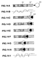
- FIGS. 14A through 14I illustrate a manner in which a laser-beam spot moves on a track, as seen from the substrate side.
- FIG. 14A illustrates an information track and a laser-beam spot 1215.
- the laser-beam spot 1215 scans the track, in which upward magnetic domains 1211 and downward magnetic domains 1211' are alternately recorded, in the direction of the arrow.
- the magnetic moments in the four compositional layers of the magnetic layer are vertically oriented and are in a state of exchange coupling with each other.
- the magnetic domains as shown in FIG. 14A are also present in the reproducing layer 1201.
- FIG. 14A illustrates an information track and a laser-beam spot 1215.
- the laser-beam spot 1215 scans the track, in which upward magnetic domains 1211 and downward magnetic domains 1211' are alternately recorded, in the direction of the arrow.
- the magnetic moments in the four compositional layers of the magnetic layer are vertically oriented and are in a state of exchange coupling with
- FIG. 14B illustrates a reproduced waveform when the same magnetic domains as those shown in FIG. 14A are recorded on a conventional optical disk.
- the amplitude of the reproduced signal becomes smaller as the size of the magnetic domain becomes small compared with the spot size.
- FIGS. 14C - 14H illustrate the behavior of the magnetic domains when the laser-beam spot scans the optical disk of the present embodiment.
- FIG. 14C illustrates the behavior of the magnetic domains when the laser-beam spot 1215 reaches the first downward magnetic domain 1211' on the track.
- reference numeral 1217 represents a portion where the magnetic moment of the reproducing layer 1201 is vertically oriented, i.e., an aperture portion which contributes to signal reproduction.
- Reference numeral 1216 represents a portion where the temperature of the disk reaches the Curie temperature of the magnetic-domain magnifying layer 1202 to disconnect the exchange coupling, and the reproducing layer 1201 becomes an in-plane-magnetizing film, i.e., a masked portion.
- the boundary between the aperture portion 1217 and the masked portion 1216 equals the isotherm of the Curie temperature Tc2 of the magnetic-domain magnifying layer 1202.
- FIG. 15 is a diagram schematically illustrating the waveform of an ordinary reproduced signal.
- the rise time ⁇ of the reproduced signal corresponds to the time required for a domain wall to move within the spot. It is necessary to set the recording frequency so that the time ⁇ is smaller than the time T min corresponding to the shortest recording mark length.
- domain walls can smoothly move by smoothing the surface of the disk by being heated by projecting Ar ions on the surface of the interference film after it has been formed. It is thereby possible to further increase the linear velocity of the disk.
- the tracks can be magnetically separated by annealing the magetic layer on the guide groove portions by projecting a high-power laser beam to provide an in-plane-magnetizing film.
- FIGS. 16A and 16B are diagrams illustrating the configuration of a fourth embodiment of the present invention.
- the fourth embodiment differs from the third embodiment in the following two items.
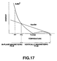
- the reproducing layer 1301 has a composition having larger saturation magnetization Ms and smaller vertical magnetic anisotropy Ku compared with the third embodiment (Ku > 0).
- the reproducing layer 1301 comprises an in-plane-magnetizing film influenced by its own demagnetizing field in spite of the exchange coupling force exerted from the magnetic-domain magnifying layer 1302.
- Tth1 when the temperature of the disk reaches the predetermined temperature Tth1, since the value of Ms is reduced, the direction of the magnetic moment of the reproducing layer 1301 becomes perpendicular to the plane of the magnetic layer caused by the exchange coupling with the magnetic-domain magnifying layer 1302.
- the value of Tth1 is desirably the temperature of the disk reached when a reproducing light beam is projected, i.e., about 100 °C.
- the Curie temperature of the reproducing layer 1301 is preferably a high temperature of at least 300 °C.
- the reproducing layer 1301 has a composition such that rare-earth-element sublattice magnetization is dominant.
- the compensation temperature is not necessarily required to be present, but the reproducing layer 1301 preferably has a compensation temperature between the room temperature and the Curie temperature. More specifically, a composition to have a compensation temperature of at least 200 °C is preferred.
- Ew represents the exchange energy which is exerted from the magnetic-domain magnifying layer 1301 to the reproducing layer 1301. Since the magnetic-domain magnifying layer 1302 comprises a vertically-magnetizing layer, a force is exerted so as to vertically magnetize the reproducing layer 1301 together with Ku. As shown in FIG. 17, at temperatures lower than Tth1, 2 ⁇ Ms2 > Ku + Ew. Hence, the direction of the magnetic moment of the reproducing layer 1301 is within the plane of the magnetic layer. If the temeperature of the disk is raised to at least Tth1, 2 ⁇ Ms2 ⁇ Ku + Ew. Hence, the direction of the magnetic moment of the reproducing layer 1301 becomes perpendicular to the plane of the magnetic layer, and magnified information pits are transferred to the reproducing layer 1301 caused by the exchange coupling exerted from the magnetic-domain magnifying layer 1302.
- the reproducing layer 1301 comprises an in-plane-magnetizing layer.
- magnetic domains in the recording layer 1304 are masked, and a reproduced signal is obtained from a trailing-end portion of the spot.
- FIGS. 18A and 18B A description will be provided with reference to FIGS. 18A and 18B in order to clarify a difference in the shape of an aperture within the spot.
- FIG. 18A is a diagram illustrating the behavior of the spot in the third embodiment.
- the region 1216 having temperatures higher than the isotherm of Tc2 within the spot 1215 is the masked region in which the reproducing layer 1201 comprises an in-plane-magnetizing film.
- the region 1217 having temperatures lower than Tc2 is the aperture region in which all the four compositional layers of the magnetic layer are in a state of exchange coupling. As described above, a signal is reproduced from this region.
- the land 1213 serving as an information track, is separated by the grooves 1214, but a magnetic film is also present on the grooves 1214.
- the spot 1215 is also projected onto the grooves 1214, noise may be generated depending on the direction of magnetization within the grooves 1214. This causes no problem when the grooves 1214 have been annealed to provide an in-plane-magnetizing film, or when the magnetization of the grooves 1214 has been initialized to be arranged in the same direction, but will cause a big problem when the magnetization of the grooves 1214 has not been initialized, or when it is intended to utilize the grooves 1214 as tracks by recording another information.
- an aperture 1317 is situated at the trailing-end side of a spot 1315. That is, the reproducing layer 1301 comprises an in-plane-magnetizing film to become a masked region at a portion having temperatures lower than Tth1, and a region having temperatures equal to or higher than Tth1 is in a state of exchange coupling with the magnetic-domain magnifying layer 1302 to become an aperture.
- a region 1318 of the aperture portion present on grooves 1314 is a very small region. Hence, there is no problem of noise or cross talk from the grooves 1314.
- noise is reduced.
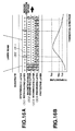
- FIGS. 19A and 19B are diagrams illustrating the configuration of a fifth embodiment of the present invention.
- the present embodiment differs from the fourth embodiment in that the Curie temperature Tc2 of a magnetic-domain magnifying layer 1402 is set to a value lower than that of the magnetic-domain magnifying layer of the fourth embodiment, so that a part of the magnetic-domain magnifying layer 1402 reaches the Curie temperature within the spot caused by irradiation of a reproducing light beam.
- two masked regions are present within the spot.
- a signal is reproduced by extracting only a portion including magnified magnetic domains made by moved domain walls, a noise component can be further removed.
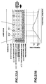
- FIG. 20 illustrates the result of measurement of the C/N ratio for the disk having the configuration of the present embodiment.
- the C/N ratio greatly decreases when the recording mark length is reduced to about 0.4 ⁇ m. This tendency is improved, though insufficiently, by using a conventional ultrahigh-resolution optical disk, but the C/N ratio more or less decreases for smaller mark lengths.
- FIGS. 21A and 21B are diagrams illustrating the configuration of a sixth embodiment of the present invention.
- the present embodiment differs from the third embodiment in that a second intermediate layer 1505, having a Curie temperature lower than the Curie temperatures of a reproducing layer 1501 and a magnetic-domain magnifying layer 1502, and higher than the Curie temperature of a first intermediate layer 1503 ,is added between the reproducing layer 1501 and the magnetic-domain magnifying layer 1502.
- the magnetic-domain magnifying layer of the third embodiment has the following two functions.
- the degree of freedom in the design of films is increased by arranging so that the second intermediate layer 1505 has the above-described function (2).
- the operation of the disk is the same as in the third embodiment.
- FIGS. 22A and 22B are diagrams illustrating the configuration of a seventh embodiment of the present invention.
- the present embodiment differs from the fifth embodiment in that a second intermediate layer 1605, having a Curie temperature lower than the Curie temperatures of a reproducing layer 1601 and a magnetic-domain magnifying layer 1602, and higher than the Curie temperature of a first intermediate layer 1603 ,is added between the reproducing layer 1501 and the magnetic-domain magnifying layer 1502.
- the degree of freedom in the design of films is increased by arranging so that the second intermediate layer 1605 has the above-described function (2).
- the operation of the disk is the same as in the fifth embodiment.
- FIGS. 23A and 23B are diagrams illustrating the configuration of an eighth embodiment of the present invention.
- an adjusting layer 1706 having a Curie temperature Tc6 lower than the Curie temperatures of a reproducing layer 1701 and a magnetic-domain magnifying layer 1702, and higher than the Curie temperature of a first intermediate layer 1703, and having large in-plane magnetic anisotropy, is provided.
- This adjusting layer 1706 has the function of adjusting the exchange coupling energy between the reproducing layer 1701 and the magnetic-domain magnifying layer 1702 in a masked portion, and increasing the masking effect of the reproducing layer 1701.
- the adjusting layer 1706 of the present embodiment also has the function of disconnecting the exchange coupling with the reproducing layer 1701 at a portion having temperatures equal to or higher than the Curie temperature Tc6.
- a configuration, in which the above-described functions are allocated to separate magnetic layers, agrees, of course, with the gist of the present invention.
Priority Applications (2)
| Application Number | Priority Date | Filing Date | Title |
|---|---|---|---|
| EP01202807A EP1158509A3 (fr) | 1993-04-02 | 1994-03-30 | Procédé d'enregistrement magnéto-optique |
| EP00200724A EP1020854A3 (fr) | 1993-04-02 | 1994-03-30 | Appareil de reproduction magnéto-optique |
Applications Claiming Priority (6)
| Application Number | Priority Date | Filing Date | Title |
|---|---|---|---|
| JP77141/93 | 1993-04-02 | ||
| JP7714193 | 1993-04-02 | ||
| JP07714193A JP3332458B2 (ja) | 1993-04-02 | 1993-04-02 | 光磁気記録媒体 |
| JP25997893A JP3412879B2 (ja) | 1993-10-18 | 1993-10-18 | 光磁気記録媒体 |
| JP259978/93 | 1993-10-18 | ||
| JP25997893 | 1993-10-18 |
Related Child Applications (1)
| Application Number | Title | Priority Date | Filing Date |
|---|---|---|---|
| EP00200724A Division EP1020854A3 (fr) | 1993-04-02 | 1994-03-30 | Appareil de reproduction magnéto-optique |
Publications (3)
| Publication Number | Publication Date |
|---|---|
| EP0618572A2 true EP0618572A2 (fr) | 1994-10-05 |
| EP0618572A3 EP0618572A3 (fr) | 1995-04-05 |
| EP0618572B1 EP0618572B1 (fr) | 2002-07-03 |
Family
ID=26418235
Family Applications (4)
| Application Number | Title | Priority Date | Filing Date |
|---|---|---|---|
| EP04075214A Withdrawn EP1426944A3 (fr) | 1993-04-02 | 1994-03-30 | Procédé de fabrication d'un support d'enregistrement magnéto-optique |
| EP00200724A Withdrawn EP1020854A3 (fr) | 1993-04-02 | 1994-03-30 | Appareil de reproduction magnéto-optique |
| EP01202807A Withdrawn EP1158509A3 (fr) | 1993-04-02 | 1994-03-30 | Procédé d'enregistrement magnéto-optique |
| EP94302309A Expired - Lifetime EP0618572B1 (fr) | 1993-04-02 | 1994-03-30 | Support d'enregistrement magnéto-optique sur lequel il est possible d'enregistrer des informations en haute densité et procédé de reproduction des informations enrégistrées |
Family Applications Before (3)
| Application Number | Title | Priority Date | Filing Date |
|---|---|---|---|
| EP04075214A Withdrawn EP1426944A3 (fr) | 1993-04-02 | 1994-03-30 | Procédé de fabrication d'un support d'enregistrement magnéto-optique |
| EP00200724A Withdrawn EP1020854A3 (fr) | 1993-04-02 | 1994-03-30 | Appareil de reproduction magnéto-optique |
| EP01202807A Withdrawn EP1158509A3 (fr) | 1993-04-02 | 1994-03-30 | Procédé d'enregistrement magnéto-optique |
Country Status (3)
| Country | Link |
|---|---|
| US (3) | US6027825A (fr) |
| EP (4) | EP1426944A3 (fr) |
| DE (1) | DE69430883T2 (fr) |
Cited By (14)
| Publication number | Priority date | Publication date | Assignee | Title |
|---|---|---|---|---|
| EP0831474A2 (fr) * | 1996-09-19 | 1998-03-25 | Canon Kabushiki Kaisha | Milieu d'enregistrement magnéto-optique, méthode et appareil de reproduction de signal |
| EP0831465A1 (fr) * | 1996-09-19 | 1998-03-25 | Canon Kabushiki Kaisha | Support d'enregistrement magnétique, procédé de fabrication et procédé pour l'enregistrement ou reproduction |
| EP0848381A2 (fr) * | 1996-12-13 | 1998-06-17 | Canon Kabushiki Kaisha | Support d'enregistrement magnéto-optique exclusivement pour reproduction, procédé de fabrication et procédé de reproduction par ce moyen |
| EP0899727A2 (fr) * | 1997-09-01 | 1999-03-03 | Canon Kabushiki Kaisha | Méthode de reproduction de signal utilisant le déplacement de paroi de domaine magnétique et appareil pour cela |
| EP0907168A2 (fr) * | 1997-10-01 | 1999-04-07 | Canon Kabushiki Kaisha | Méthode et appareil d'enregistrement / reproduction magnéto-optique |
| EP0913818A1 (fr) * | 1996-07-12 | 1999-05-06 | Hitachi Maxell, Ltd. | Support d'enregistrement magneto-optique, procede de reproduction et dispositif de reproduction |
| EP0994472A1 (fr) * | 1998-10-16 | 2000-04-19 | Canon Kabushiki Kaisha | Milieu d'enregistrement magnétique |
| US6118736A (en) * | 1997-09-25 | 2000-09-12 | Tosoh Corporation | Magneto-optical recording medium having a reading layer in which transferred recording marks are extended |
| EP1052634A1 (fr) * | 1998-01-30 | 2000-11-15 | Sony Corporation | Support d'enregistrement magneto-optique et procede de reproduction de signaux |
| US6221219B1 (en) * | 1998-09-28 | 2001-04-24 | Canon Kabushiki Kaisha | Magneto-optical medium and process for production thereof |
| WO2001093259A1 (fr) * | 2000-05-31 | 2001-12-06 | Matsushita Electric Industrial Co., Ltd. | Support magneto-optique d'enregistrement, procede de fabrication associe, et procede et dispositif de lecture de ce support |
| WO2003015086A1 (fr) * | 2001-08-03 | 2003-02-20 | Koninklijke Philips Electronics N.V. | Systemes d'enregistrement optiques reinscriptibles |
| US6577560B2 (en) | 1999-06-28 | 2003-06-10 | Fujitsu Limited | Magneto-optic recording medium in which magnetic partition tracks are removed for high track density |
| US7535803B2 (en) | 2004-08-02 | 2009-05-19 | Panasonic Corporation | Method for recording to and reproducing from a magnetic recording medium, recording and reproduction device for the same, and magnetic recording medium |
Families Citing this family (69)
| Publication number | Priority date | Publication date | Assignee | Title |
|---|---|---|---|---|
| EP1426944A3 (fr) * | 1993-04-02 | 2008-01-23 | Canon Kabushiki Kaisha | Procédé de fabrication d'un support d'enregistrement magnéto-optique |
| WO1996002925A1 (fr) * | 1994-07-18 | 1996-02-01 | Migaku Takahashi | Couche mince magnetique et procede de fabrication |
| JPH10275369A (ja) | 1997-01-31 | 1998-10-13 | Canon Inc | 情報記録媒体の製造方法および該方法による情報記録媒体 |
| JPH10269502A (ja) * | 1997-03-26 | 1998-10-09 | Fujitsu Ltd | 磁気記録方法および磁気ディスク装置 |
| JPH11134732A (ja) | 1997-08-29 | 1999-05-21 | Canon Inc | 情報記録再生方法 |
| JP2000298888A (ja) | 1999-04-15 | 2000-10-24 | Canon Inc | 光磁気記録媒体 |
| JP2000331397A (ja) * | 1999-05-19 | 2000-11-30 | Sony Corp | 光出力調整装置及び光出力調整方法 |
| US6504797B1 (en) * | 1999-06-25 | 2003-01-07 | Matsushita Electric Industrial Co., Ltd. | Magneto-optical recording medium having multiple magnetic layers and reproducing method thereof |
| JP3995833B2 (ja) * | 1999-06-29 | 2007-10-24 | シャープ株式会社 | 光磁気記録媒体 |
| JP2001023254A (ja) | 1999-07-02 | 2001-01-26 | Canon Inc | 光磁気記録テスト方法及び光磁気記録再生装置 |
| JP2001126332A (ja) | 1999-10-21 | 2001-05-11 | Canon Inc | 光磁気記録媒体の製造方法 |
| JP2001243665A (ja) | 1999-11-26 | 2001-09-07 | Canon Inc | 光ディスク基板成型用スタンパおよびその製造方法 |
| US6551471B1 (en) | 1999-11-30 | 2003-04-22 | Canon Kabushiki Kaisha | Ionization film-forming method and apparatus |
| US6665242B2 (en) | 1999-12-02 | 2003-12-16 | Canon Kabushiki Kaisha | Optical information reproducing apparatus having circuit for adjusting reproducing power |
| JP2001202666A (ja) | 2000-01-18 | 2001-07-27 | Canon Inc | 再生パワーテスト方法及び光学的情報再生装置 |
| JP2001229589A (ja) | 2000-02-16 | 2001-08-24 | Canon Inc | 光磁気記録媒体及び光磁気記録装置 |
| JP2001307393A (ja) | 2000-04-25 | 2001-11-02 | Canon Inc | 光磁気再生装置 |
| KR100469613B1 (ko) * | 2000-08-18 | 2005-02-02 | 마쯔시다덴기산교 가부시키가이샤 | 정보 기록 매체 및 그 기록/재생 방법 |
| US6826131B2 (en) | 2000-10-11 | 2004-11-30 | Matsushita Electric Industrial Co., Ltd. | Magneto-optical recording medium having multiple magnetic layers |
| US6579635B2 (en) | 2000-10-12 | 2003-06-17 | International Business Machines Corporation | Smoothing and stabilization of domain walls in perpendicularly polarized magnetic films |
| US6767656B2 (en) * | 2000-10-26 | 2004-07-27 | Fujitsu Limited | Magneto-optical recording medium and method of reproducing the same |
| JP2002203343A (ja) * | 2000-10-31 | 2002-07-19 | Matsushita Electric Ind Co Ltd | 光ディスクおよびその製造方法 |
| JP2002157792A (ja) | 2000-11-15 | 2002-05-31 | Canon Inc | 光磁気記録媒体及び該媒体のための再生方法、再生装置 |
| JP2002208193A (ja) | 2001-01-09 | 2002-07-26 | Canon Inc | 光磁気記録媒体およびその情報再生方法 |
| JP4350312B2 (ja) | 2001-01-12 | 2009-10-21 | キヤノン株式会社 | 磁壁移動型光磁気記録媒体および情報再生方法 |
| JP2002216403A (ja) * | 2001-01-16 | 2002-08-02 | Canon Inc | 光磁気ディスクのアニール方法、及び光磁気ディスク |
| JPWO2002077987A1 (ja) * | 2001-03-26 | 2004-07-15 | 日立マクセル株式会社 | 光磁気記録媒体及びその再生方法 |
| JP2002298360A (ja) | 2001-03-30 | 2002-10-11 | Canon Inc | 情報記録媒体への情報記録方法及び情報記録装置 |
| JP4610770B2 (ja) * | 2001-03-30 | 2011-01-12 | キヤノン株式会社 | 光ディスク原盤の製造方法 |
| JP2002319195A (ja) | 2001-04-19 | 2002-10-31 | Matsushita Electric Ind Co Ltd | 光ディスク及びそのトラック間の磁気的遮断処理方法 |
| US7187635B2 (en) * | 2001-04-19 | 2007-03-06 | Canon Kabushiki Kaisha | Optical information reproducing method and apparatus for performing reproduction compensation |
| JP2002319200A (ja) * | 2001-04-19 | 2002-10-31 | Matsushita Electric Ind Co Ltd | 光ディスクおよびその製造方法 |
| JP2002319198A (ja) | 2001-04-19 | 2002-10-31 | Matsushita Electric Ind Co Ltd | 光磁気記録媒体およびその製造方法と製造装置 |
| JP2002319197A (ja) | 2001-04-19 | 2002-10-31 | Matsushita Electric Ind Co Ltd | 光磁気記録媒体およびその製造方法 |
| US20040076083A1 (en) * | 2001-04-19 | 2004-04-22 | Koichiro Nishikawa | Magneto-optical record medium |
| JP2002319196A (ja) | 2001-04-19 | 2002-10-31 | Matsushita Electric Ind Co Ltd | 光ディスクおよびそのトラック間の磁気的遮断処理方法 |
| JP2002352484A (ja) * | 2001-05-25 | 2002-12-06 | Fujitsu Ltd | 光磁気記録媒体 |
| JP3930281B2 (ja) | 2001-09-27 | 2007-06-13 | 株式会社東芝 | 垂直磁気記録再生装置におけるノイズを低下する方法 |
| US20040252624A1 (en) * | 2001-10-25 | 2004-12-16 | Motoyoshi Murakami | Method of forming film on optical disk |
| AU2002349717A1 (en) * | 2001-11-29 | 2003-06-10 | Matsushita Electric Industrial Co., Ltd. | Magneto-optical recording medium and manufacturing method thereof |
| JP2003257100A (ja) * | 2001-12-27 | 2003-09-12 | Canon Inc | 磁壁移動型光磁気記録媒体の記録方法 |
| JP4078084B2 (ja) * | 2002-01-28 | 2008-04-23 | キヤノン株式会社 | イオン化成膜方法及び装置 |
| JP3958084B2 (ja) | 2002-02-08 | 2007-08-15 | キヤノン株式会社 | 光学的記録再生方法 |
| JPWO2003071532A1 (ja) * | 2002-02-25 | 2005-06-16 | 富士通株式会社 | 光磁気記録媒体及びその記録再生装置 |
| JP2003263806A (ja) * | 2002-03-12 | 2003-09-19 | Canon Inc | 光磁気記録媒体 |
| AU2003202535A1 (en) * | 2002-04-01 | 2003-10-23 | Sony Corporation | Recording and reproducing apparatus for recording and reproducing information to and from a magneto-optical storage medium |
| JP2003317337A (ja) * | 2002-04-26 | 2003-11-07 | Canon Inc | 光磁気記録媒体及び記録方法 |
| JP2003338053A (ja) * | 2002-05-20 | 2003-11-28 | Canon Inc | 光記録媒体 |
| JP4095364B2 (ja) * | 2002-07-19 | 2008-06-04 | キヤノン株式会社 | 磁壁移動型光磁気記録媒体の記録再生装置 |
| JP2004055047A (ja) * | 2002-07-19 | 2004-02-19 | Canon Inc | 光磁気記録媒体およびその製造方法 |
| US7145847B2 (en) * | 2002-08-28 | 2006-12-05 | Canon Kabushiki Kaisha | Annealed optical information recording medium and optical information recording/reproducing apparatus for the same |
| US20040057343A1 (en) * | 2002-09-18 | 2004-03-25 | Matsushita Electric Industrial Co., Ltd. | Magnetic recording medium, method for producing the same and magnetic recording/reproducing apparatus |
| US7235313B2 (en) * | 2002-10-08 | 2007-06-26 | Matsushita Electic Industrial Co., Ltd. | Magneto-optical recording medium, method of manufacturing magneto-optical recording medium, method of recording on magneto-optical recording medium, and method of reproduction from magneto-optical recording medium |
| JP2004133989A (ja) * | 2002-10-09 | 2004-04-30 | Canon Inc | 光磁気記録媒体及びその製造方法 |
| JP3977238B2 (ja) * | 2002-12-03 | 2007-09-19 | キヤノン株式会社 | 光磁気記録媒体 |
| JP2004192677A (ja) * | 2002-12-09 | 2004-07-08 | Canon Inc | 磁壁移動型光磁気記録媒体 |
| JP2005011385A (ja) * | 2003-06-16 | 2005-01-13 | Canon Inc | 磁区拡大型光磁気再生方法及び装置 |
| JP2005025889A (ja) * | 2003-07-04 | 2005-01-27 | Canon Inc | 光学的記録媒体への情報記録方法 |
| JP2005050400A (ja) * | 2003-07-30 | 2005-02-24 | Canon Inc | 光磁気記録媒体 |
| JP2005174518A (ja) * | 2003-12-15 | 2005-06-30 | Canon Inc | 磁性記録媒体及びその製造方法 |
| JP2005251369A (ja) * | 2004-02-02 | 2005-09-15 | Canon Inc | 光磁気記録媒体 |
| CN1922675A (zh) * | 2004-02-27 | 2007-02-28 | 松下电器产业株式会社 | 磁记录介质及其制造方法和制造装置、磁记录介质的记录再现方法和记录再现装置 |
| JP2005243186A (ja) * | 2004-02-27 | 2005-09-08 | Tdk Corp | 磁気記録再生装置及び磁気記録媒体 |
| EP1755118A4 (fr) * | 2004-04-28 | 2008-11-26 | Panasonic Corp | Support d"enregistrement magnetique et procede de fabrication, equipement de fabrication, procede d"enregistrement/de reproduction et son dispositif de reproduction d"enregistrement |
| US20060024531A1 (en) * | 2004-07-27 | 2006-02-02 | Matsushita Electric Industrial Co., Ltd. | Magnetic recording medium and method for manufacturing same, and method for recording and reproducing with magnetic recording medium |
| JP2006338717A (ja) * | 2005-05-31 | 2006-12-14 | Canon Inc | 光ディスク |
| JP2009223976A (ja) * | 2008-03-17 | 2009-10-01 | Tdk Corp | 磁気記録装置及び磁気記録媒体 |
| US8264788B2 (en) * | 2009-02-23 | 2012-09-11 | Seagate Technology Llc | Discrete track media (DTM) design and fabrication for heat assisted magnetic recording (HAMR) |
| EP2333772A1 (fr) * | 2009-12-07 | 2011-06-15 | Thomson Licensing | Procédé et appareil pour la lecture et/ou l'écriture d'un support d'enregistrement optique |
Citations (7)
| Publication number | Priority date | Publication date | Assignee | Title |
|---|---|---|---|---|
| EP0343727A1 (fr) * | 1988-05-24 | 1989-11-29 | Koninklijke Philips Electronics N.V. | Procédé pour le balayage optique d'une face d'information et porteurs d'enregistrement optiques et dispositif de balayage pour la mise en oeuvre de ce procédé |
| EP0352548A2 (fr) * | 1988-07-13 | 1990-01-31 | Sony Corporation | Méthode d'enregistrement thermo-magnétique |
| EP0492553A2 (fr) * | 1990-12-27 | 1992-07-01 | Sony Corporation | Support d'enregistrement magnétooptique |
| EP0498461A2 (fr) * | 1991-02-08 | 1992-08-12 | Sony Corporation | Système et méthode pour la réproduction des signaux enregistrés sur un milieu d'enregistrement magnéto-optique |
| EP0498440A2 (fr) * | 1991-02-08 | 1992-08-12 | Sony Corporation | Milieu d'enregistrement magnéto-optique |
| EP0522500A2 (fr) * | 1991-07-08 | 1993-01-13 | Sharp Kabushiki Kaisha | Dispositif de tête optique |
| EP0524745A2 (fr) * | 1991-07-08 | 1993-01-27 | Sharp Kabushiki Kaisha | Milieu d'enregistrement magnéto-optique sur lequel l'enregistrement avec fonction de surécriture est effectué |
Family Cites Families (22)
| Publication number | Priority date | Publication date | Assignee | Title |
|---|---|---|---|---|
| US4412264A (en) * | 1979-10-22 | 1983-10-25 | Kokusai Denshin Denwa Co., Ltd. | Magneto-optic recording medium |
| CA1185013A (fr) * | 1981-01-14 | 1985-04-02 | Kenji Ohta | Support de memoire magneto-optique |
| JPS61206950A (ja) * | 1985-03-11 | 1986-09-13 | Nippon Kogaku Kk <Nikon> | 同時消録型光磁気記録及び再生兼用装置のピツクアツプ |
| JPS62137754A (ja) * | 1985-12-09 | 1987-06-20 | Canon Inc | 光磁気再生方法 |
| JPS62219202A (ja) * | 1986-03-20 | 1987-09-26 | Hitachi Ltd | 磁性メモリ装置 |
| EP0258978B1 (fr) * | 1986-07-08 | 1998-10-07 | Canon Kabushiki Kaisha | Milieu d'enregistrement magnéto-optique permettant la surécriture avec deux ou plus de deux couches magnétiques et méthode d'enregistrement l'utilisant |
| JPS63148445A (ja) * | 1986-12-11 | 1988-06-21 | Fujitsu Ltd | 光磁気デイスク |
| US4965780A (en) * | 1987-08-12 | 1990-10-23 | Digital Equipment Corporation | Magneto-optical data recording device using a wavelength and polarization-sensitive splitter |
| DE3889203T2 (de) * | 1987-11-30 | 1994-11-03 | Sony Corp | Methode zum optischen Abtasten eines Signals aus einem magneto-optischen Speichermedium. |
| JPH01189039A (ja) * | 1988-01-22 | 1989-07-28 | Mitsubishi Electric Corp | 光学式情報記録担体 |
| JP2698852B2 (ja) * | 1988-03-01 | 1998-01-19 | 株式会社リコー | 光磁気記録方法 |
| NL8900362A (nl) * | 1989-02-15 | 1990-09-03 | Philips Nv | Werkwijze en inrichting voor het inschrijven en uitlezen van een magneto-optische registratiedrager. |
| JPH02227844A (ja) * | 1989-02-28 | 1990-09-11 | Toshiba Corp | 光磁気記録媒体及び光磁気記録再生装置 |
| JP2846342B2 (ja) * | 1989-06-07 | 1999-01-13 | 株式会社日立製作所 | 高密度光再生装置 |
| US5168482A (en) * | 1989-08-31 | 1992-12-01 | Sony Corporation | Magnetooptical recording and playback method employing multi-layer recording medium with record holding layer and playback layer |
| JP2910084B2 (ja) | 1989-09-06 | 1999-06-23 | ソニー株式会社 | 光磁気記録媒体における信号再生方法 |
| JPH03263637A (ja) * | 1990-03-12 | 1991-11-25 | Fujitsu Ltd | 光磁気ディスクの記録再生方法及び光磁気ディスク装置 |
| JPH0413253A (ja) * | 1990-05-02 | 1992-01-17 | Sharp Corp | 光磁気メモリ素子及びその作製方法 |
| JPH04105236A (ja) * | 1990-08-27 | 1992-04-07 | Nec Corp | 磁気記録方式及び消去方式及び読出方式 |
| JPH04345940A (ja) * | 1991-05-23 | 1992-12-01 | Ricoh Co Ltd | 光磁気記録媒体 |
| JPH06103622A (ja) * | 1992-09-18 | 1994-04-15 | Nikon Corp | R層を有するオーバーライト可能な光磁気記録媒体 |
| EP1426944A3 (fr) * | 1993-04-02 | 2008-01-23 | Canon Kabushiki Kaisha | Procédé de fabrication d'un support d'enregistrement magnéto-optique |
-
1994
- 1994-03-30 EP EP04075214A patent/EP1426944A3/fr not_active Withdrawn
- 1994-03-30 DE DE69430883T patent/DE69430883T2/de not_active Expired - Fee Related
- 1994-03-30 EP EP00200724A patent/EP1020854A3/fr not_active Withdrawn
- 1994-03-30 EP EP01202807A patent/EP1158509A3/fr not_active Withdrawn
- 1994-03-30 EP EP94302309A patent/EP0618572B1/fr not_active Expired - Lifetime
-
1997
- 1997-06-05 US US08/869,921 patent/US6027825A/en not_active Expired - Lifetime
-
1999
- 1999-12-23 US US09/471,190 patent/US6403148B1/en not_active Expired - Lifetime
-
2000
- 2000-10-13 US US09/689,718 patent/US6399174B1/en not_active Expired - Lifetime
Patent Citations (7)
| Publication number | Priority date | Publication date | Assignee | Title |
|---|---|---|---|---|
| EP0343727A1 (fr) * | 1988-05-24 | 1989-11-29 | Koninklijke Philips Electronics N.V. | Procédé pour le balayage optique d'une face d'information et porteurs d'enregistrement optiques et dispositif de balayage pour la mise en oeuvre de ce procédé |
| EP0352548A2 (fr) * | 1988-07-13 | 1990-01-31 | Sony Corporation | Méthode d'enregistrement thermo-magnétique |
| EP0492553A2 (fr) * | 1990-12-27 | 1992-07-01 | Sony Corporation | Support d'enregistrement magnétooptique |
| EP0498461A2 (fr) * | 1991-02-08 | 1992-08-12 | Sony Corporation | Système et méthode pour la réproduction des signaux enregistrés sur un milieu d'enregistrement magnéto-optique |
| EP0498440A2 (fr) * | 1991-02-08 | 1992-08-12 | Sony Corporation | Milieu d'enregistrement magnéto-optique |
| EP0522500A2 (fr) * | 1991-07-08 | 1993-01-13 | Sharp Kabushiki Kaisha | Dispositif de tête optique |
| EP0524745A2 (fr) * | 1991-07-08 | 1993-01-27 | Sharp Kabushiki Kaisha | Milieu d'enregistrement magnéto-optique sur lequel l'enregistrement avec fonction de surécriture est effectué |
Non-Patent Citations (3)
| Title |
|---|
| IEEE TRANSACTIONS ON CONSUMER ELECTRONICS, vol.38, no.3, August 1992, NEW YORK US pages 660 - 664, XP000311908 YOSHIMURA ET AL. 'LARGE-CAPACITY MAGNETO-OPTICAL DISK SYSTEM USING MAGNETICALLY INDUCED SUPER RESOLUTION' * |
| JAPANESE JOURNAL OF APPLIED PHYSICS PART 1, vol.31, no.2B, February 1992, TOKYO JP pages 529 - 533, XP000323480 FUKUMOTO ET AL. 'Superresolution of Optical Disks Using a Small Aperture' * |
| JAPANESE JOURNAL OF APPLIED PHYSICS PART 1, vol.31, no.2B, February 1992, TOKYO JP pages 568 - 575, XP000323484 KANEKO ET AL. 'Multilayered Magneto-Optical Disks for Magnetically Induced Superresolution' * |
Cited By (29)
| Publication number | Priority date | Publication date | Assignee | Title |
|---|---|---|---|---|
| EP0913818A1 (fr) * | 1996-07-12 | 1999-05-06 | Hitachi Maxell, Ltd. | Support d'enregistrement magneto-optique, procede de reproduction et dispositif de reproduction |
| US6424601B1 (en) | 1996-07-12 | 2002-07-23 | Hitachi Maxell, Ltd. | Magneto-optical recording media having an auxiliary magnetic layer |
| EP0913818A4 (fr) * | 1996-07-12 | 2001-04-18 | Hitachi Maxell | Support d'enregistrement magneto-optique, procede de reproduction et dispositif de reproduction |
| US6403205B1 (en) | 1996-09-19 | 2002-06-11 | Canon Kabushiki Kaisha | Magnetic recording medium capable of reproducing information by displacing magnetic wall and recording-reproducing method therefor |
| EP0831465A1 (fr) * | 1996-09-19 | 1998-03-25 | Canon Kabushiki Kaisha | Support d'enregistrement magnétique, procédé de fabrication et procédé pour l'enregistrement ou reproduction |
| EP0831474A3 (fr) * | 1996-09-19 | 1998-08-26 | Canon Kabushiki Kaisha | Milieu d'enregistrement magnéto-optique, méthode et appareil de reproduction de signal |
| US5936915A (en) * | 1996-09-19 | 1999-08-10 | Canon Kabushiki Kaisha | Magneto-optical medium for reproducing information by the utilization of magnetic wall movement, and signal reproducing method |
| EP0831474A2 (fr) * | 1996-09-19 | 1998-03-25 | Canon Kabushiki Kaisha | Milieu d'enregistrement magnéto-optique, méthode et appareil de reproduction de signal |
| US6265062B1 (en) | 1996-09-19 | 2001-07-24 | Canon Kabushiki Kaisha | Magnetic recording medium capable of reproducing information by displacing magnetic wall and recording-reproducing method therefor |
| EP0848381A2 (fr) * | 1996-12-13 | 1998-06-17 | Canon Kabushiki Kaisha | Support d'enregistrement magnéto-optique exclusivement pour reproduction, procédé de fabrication et procédé de reproduction par ce moyen |
| EP0848381A3 (fr) * | 1996-12-13 | 1999-04-07 | Canon Kabushiki Kaisha | Support d'enregistrement magnéto-optique exclusivement pour reproduction, procédé de fabrication et procédé de reproduction par ce moyen |
| US5962154A (en) * | 1996-12-13 | 1999-10-05 | Canon Kabushiki Kaisha | Magneto-optical recording medium exclusively for reproduction, method of manufacturing the same and method of reproducing information from the medium |
| EP0899727A3 (fr) * | 1997-09-01 | 2000-03-15 | Canon Kabushiki Kaisha | Méthode de reproduction de signal utilisant le déplacement de paroi de domaine magnétique et appareil pour cela |
| EP0899727A2 (fr) * | 1997-09-01 | 1999-03-03 | Canon Kabushiki Kaisha | Méthode de reproduction de signal utilisant le déplacement de paroi de domaine magnétique et appareil pour cela |
| US6345016B1 (en) | 1997-09-01 | 2002-02-05 | Canon Kabushiki Kaisha | Signal-reproducing method and apparatus utilizing light beam generated temperature distribution and magnetic domain wall displacement |
| US6118736A (en) * | 1997-09-25 | 2000-09-12 | Tosoh Corporation | Magneto-optical recording medium having a reading layer in which transferred recording marks are extended |
| US6246641B1 (en) | 1997-10-01 | 2001-06-12 | Canon Kabushiki Kaisha | Magneto-optical recording-reproducing method and apparatus utilizing domain wall displacement |
| EP0907168A3 (fr) * | 1997-10-01 | 2000-03-22 | Canon Kabushiki Kaisha | Méthode et appareil d'enregistrement / reproduction magnéto-optique |
| EP0907168A2 (fr) * | 1997-10-01 | 1999-04-07 | Canon Kabushiki Kaisha | Méthode et appareil d'enregistrement / reproduction magnéto-optique |
| EP1052634A1 (fr) * | 1998-01-30 | 2000-11-15 | Sony Corporation | Support d'enregistrement magneto-optique et procede de reproduction de signaux |
| EP1052634A4 (fr) * | 1998-01-30 | 2006-12-06 | Sony Corp | Support d'enregistrement magneto-optique et procede de reproduction de signaux |
| US6221219B1 (en) * | 1998-09-28 | 2001-04-24 | Canon Kabushiki Kaisha | Magneto-optical medium and process for production thereof |
| EP0994472A1 (fr) * | 1998-10-16 | 2000-04-19 | Canon Kabushiki Kaisha | Milieu d'enregistrement magnétique |
| US6577560B2 (en) | 1999-06-28 | 2003-06-10 | Fujitsu Limited | Magneto-optic recording medium in which magnetic partition tracks are removed for high track density |
| WO2001093259A1 (fr) * | 2000-05-31 | 2001-12-06 | Matsushita Electric Industrial Co., Ltd. | Support magneto-optique d'enregistrement, procede de fabrication associe, et procede et dispositif de lecture de ce support |
| US7012857B2 (en) | 2000-05-31 | 2006-03-14 | Matsushita Electric Industrial Co., Ltd. | Magneto optical recording medium having a multilayer recording film of different thickness |
| CN100377241C (zh) * | 2000-05-31 | 2008-03-26 | 松下电器产业株式会社 | 磁光记录介质和其制造方法以及用于对其进行读出的方法 |
| WO2003015086A1 (fr) * | 2001-08-03 | 2003-02-20 | Koninklijke Philips Electronics N.V. | Systemes d'enregistrement optiques reinscriptibles |
| US7535803B2 (en) | 2004-08-02 | 2009-05-19 | Panasonic Corporation | Method for recording to and reproducing from a magnetic recording medium, recording and reproduction device for the same, and magnetic recording medium |
Also Published As
| Publication number | Publication date |
|---|---|
| US6399174B1 (en) | 2002-06-04 |
| US6027825A (en) | 2000-02-22 |
| DE69430883D1 (de) | 2002-08-08 |
| EP1426944A3 (fr) | 2008-01-23 |
| EP0618572A3 (fr) | 1995-04-05 |
| EP1426944A2 (fr) | 2004-06-09 |
| DE69430883T2 (de) | 2003-01-23 |
| EP1158509A3 (fr) | 2002-01-02 |
| EP1020854A3 (fr) | 2000-12-20 |
| EP0618572B1 (fr) | 2002-07-03 |
| EP1020854A2 (fr) | 2000-07-19 |
| EP1158509A2 (fr) | 2001-11-28 |
| US6403148B1 (en) | 2002-06-11 |
Similar Documents
| Publication | Publication Date | Title |
|---|---|---|
| US6403148B1 (en) | Magnetooptical recording medium on which high-density information can be recorded and method of reproducing the recorded information | |
| JP3332458B2 (ja) | 光磁気記録媒体 | |
| US5616428A (en) | Magnetooptical recording medium and information recording and reproducing methods using the recording medium | |
| JP3332750B2 (ja) | 磁気記録媒体、記録方法、再生方法、及び、磁性記録媒体の製造方法 | |
| US6307816B1 (en) | Magneto-optical recording medium, and information reproducing method using the medium | |
| EP1422708A1 (fr) | Support d'enregistrement magnéto-optique et méthode de reproduction associée | |
| JP2809991B2 (ja) | 光磁気記録媒体及び該媒体に記録された情報の再生方法 | |
| US5493545A (en) | Magnetooptical recording medium with overwrite capabilities and method for using the same | |
| JPH06124500A (ja) | 光磁気記録媒体及び該媒体の再生方法 | |
| EP0698881A1 (fr) | Milieu d'enregistrement magnéto-optique et méthode de reproduction de l'information à partir du milieu | |
| EP0668585B1 (fr) | Méthode et système d'enregistrement d'information utilisant un milieu d'enregistrement magnétooptique | |
| US7522479B2 (en) | Domain wall displacement for magneto-optical recording medium having multiple magnetic layers | |
| JP3474464B2 (ja) | 光磁気記録媒体 | |
| USRE38501E1 (en) | Magnetooptical recording medium and information recording and reproducing methods using the recording medium | |
| JP3631194B2 (ja) | 光磁気記録媒体の製造方法 | |
| JPH11328762A (ja) | 光磁気記録媒体 | |
| JP3332905B2 (ja) | 光磁気記録媒体の再生方法および再生装置 | |
| JP3592399B2 (ja) | 光磁気記録媒体 | |
| JPH07254176A (ja) | 光磁気記録媒体および該媒体を用いた情報再生方法 | |
| JP2001195792A (ja) | 光磁気記録媒体及びその再生方法 | |
| JP2000021036A (ja) | 磁性記録媒体およびその再生方法 | |
| JPH10308043A (ja) | 情報再生方法及び情報再生装置 | |
| JPH11296925A (ja) | 光磁気記録媒体、再生方法及び再生装置 | |
| JP2001344840A (ja) | 光磁気記録媒体および再生方法 |
Legal Events
| Date | Code | Title | Description |
|---|---|---|---|
| PUAI | Public reference made under article 153(3) epc to a published international application that has entered the european phase |
Free format text: ORIGINAL CODE: 0009012 |
|
| AK | Designated contracting states |
Kind code of ref document: A2 Designated state(s): DE FR GB IT NL |
|
| PUAL | Search report despatched |
Free format text: ORIGINAL CODE: 0009013 |
|
| AK | Designated contracting states |
Kind code of ref document: A3 Designated state(s): DE FR GB IT NL |
|
| 17P | Request for examination filed |
Effective date: 19950818 |
|
| 17Q | First examination report despatched |
Effective date: 19980129 |
|
| GRAG | Despatch of communication of intention to grant |
Free format text: ORIGINAL CODE: EPIDOS AGRA |
|
| GRAG | Despatch of communication of intention to grant |
Free format text: ORIGINAL CODE: EPIDOS AGRA |
|
| GRAG | Despatch of communication of intention to grant |
Free format text: ORIGINAL CODE: EPIDOS AGRA |
|
| GRAH | Despatch of communication of intention to grant a patent |
Free format text: ORIGINAL CODE: EPIDOS IGRA |
|
| GRAH | Despatch of communication of intention to grant a patent |
Free format text: ORIGINAL CODE: EPIDOS IGRA |
|
| GRAA | (expected) grant |
Free format text: ORIGINAL CODE: 0009210 |
|
| AK | Designated contracting states |
Kind code of ref document: B1 Designated state(s): DE FR GB IT NL |
|
| REF | Corresponds to: |
Ref document number: 69430883 Country of ref document: DE Date of ref document: 20020808 |
|
| ET | Fr: translation filed | ||
| PLBE | No opposition filed within time limit |
Free format text: ORIGINAL CODE: 0009261 |
|
| STAA | Information on the status of an ep patent application or granted ep patent |
Free format text: STATUS: NO OPPOSITION FILED WITHIN TIME LIMIT |
|
| 26N | No opposition filed |
Effective date: 20030404 |
|
| PGFP | Annual fee paid to national office [announced via postgrant information from national office to epo] |
Ref country code: NL Payment date: 20090318 Year of fee payment: 16 |
|
| PGFP | Annual fee paid to national office [announced via postgrant information from national office to epo] |
Ref country code: GB Payment date: 20090331 Year of fee payment: 16 |
|
| PGFP | Annual fee paid to national office [announced via postgrant information from national office to epo] |
Ref country code: IT Payment date: 20090306 Year of fee payment: 16 Ref country code: DE Payment date: 20090331 Year of fee payment: 16 |
|
| PGFP | Annual fee paid to national office [announced via postgrant information from national office to epo] |
Ref country code: FR Payment date: 20090325 Year of fee payment: 16 |
|
| REG | Reference to a national code |
Ref country code: NL Ref legal event code: V1 Effective date: 20101001 |
|
| GBPC | Gb: european patent ceased through non-payment of renewal fee |
Effective date: 20100330 |
|
| REG | Reference to a national code |
Ref country code: FR Ref legal event code: ST Effective date: 20101130 |
|
| PG25 | Lapsed in a contracting state [announced via postgrant information from national office to epo] |
Ref country code: NL Free format text: LAPSE BECAUSE OF NON-PAYMENT OF DUE FEES Effective date: 20101001 Ref country code: FR Free format text: LAPSE BECAUSE OF NON-PAYMENT OF DUE FEES Effective date: 20100331 |
|
| PG25 | Lapsed in a contracting state [announced via postgrant information from national office to epo] |
Ref country code: DE Free format text: LAPSE BECAUSE OF NON-PAYMENT OF DUE FEES Effective date: 20101001 |
|
| PG25 | Lapsed in a contracting state [announced via postgrant information from national office to epo] |
Ref country code: GB Free format text: LAPSE BECAUSE OF NON-PAYMENT OF DUE FEES Effective date: 20100330 Ref country code: IT Free format text: LAPSE BECAUSE OF NON-PAYMENT OF DUE FEES Effective date: 20100330 |