EP0615013A1 - Métier à tisser en grande largeur à fausse navette - Google Patents
Métier à tisser en grande largeur à fausse navette Download PDFInfo
- Publication number
- EP0615013A1 EP0615013A1 EP94101546A EP94101546A EP0615013A1 EP 0615013 A1 EP0615013 A1 EP 0615013A1 EP 94101546 A EP94101546 A EP 94101546A EP 94101546 A EP94101546 A EP 94101546A EP 0615013 A1 EP0615013 A1 EP 0615013A1
- Authority
- EP
- European Patent Office
- Prior art keywords
- sley
- guide elements
- weaving
- wide
- machine according
- Prior art date
- Legal status (The legal status is an assumption and is not a legal conclusion. Google has not performed a legal analysis and makes no representation as to the accuracy of the status listed.)
- Granted
Links
Images


Classifications
-
- D—TEXTILES; PAPER
- D03—WEAVING
- D03D—WOVEN FABRICS; METHODS OF WEAVING; LOOMS
- D03D47/00—Looms in which bulk supply of weft does not pass through shed, e.g. shuttleless looms, gripper shuttle looms, dummy shuttle looms
- D03D47/12—Looms in which bulk supply of weft does not pass through shed, e.g. shuttleless looms, gripper shuttle looms, dummy shuttle looms wherein single picks of weft thread are inserted, i.e. with shedding between each pick
- D03D47/24—Looms in which bulk supply of weft does not pass through shed, e.g. shuttleless looms, gripper shuttle looms, dummy shuttle looms wherein single picks of weft thread are inserted, i.e. with shedding between each pick by gripper or dummy shuttle
-
- D—TEXTILES; PAPER
- D03—WEAVING
- D03D—WOVEN FABRICS; METHODS OF WEAVING; LOOMS
- D03D49/00—Details or constructional features not specially adapted for looms of a particular type
- D03D49/60—Construction or operation of slay
Definitions
- the invention relates to a wide weaving machine, in particular for the production of flat woven paper machine clothing or other technical fabrics with warp and weft threads, preferably with widths of more than 6 m, with a weaving sway oscillating in the direction of the warp threads, and a method for moving guide elements for Projectiles on wide weaving machines with swinging sley.
- Weaving machines for the production of flat-woven paper machine clothing or similar technical fabrics which are manufactured in widths of 6 - 12 m with high warp tensions and shop slinging forces of up to 5 to / m weaving width, are special weaving machines and cannot be compared with the category of textile weaving machines.
- Characteristic of the textile weaving machines are their narrow weaving width, their high number of wefts per minute and their light construction adapted to these conditions, which is made clear by the drive of the sley, which is usual with these looms, by means of an oscillating shaft on which the shop supports carrying the sley sit and synchronize with it move. In these machines, this oscillating shaft is driven by a cam mechanism (FIG. 10).
- weft insertion is currently carried out by means of so-called rapier weavers, which in terms of their dimensions and their mass - which not only accelerate but also have to be brought to a standstill safely and accurately - larger weft numbers not allow.
- the unstable rifle flight also limited the rifle speeds and thus the performance increase of these machines.
- the invention is therefore based on the object of designing a wide weaving machine which eliminates the aforementioned disadvantages which have hitherto hindered an increase in performance in these special weaving machines.
- a second movement is superimposed on the guide elements.
- the guide elements which are necessary for guiding the projectiles, emerge from the compartment after the weft entry and thus no longer interfere with the striking of the reed against the fabric edge.
- it is therefore a movement component which is superimposed essentially in the direction perpendicular to the warp threads in addition to the usual weaving movement, which takes place essentially in the direction of the warp threads on a circular arc.
- This movement which additionally causes the guide elements to emerge from the compartment, can be achieved by superimposing a second movement on the sley. If the sley also moves synchronously in the vertical direction, the guide elements can be firmly attached to the sley so that they do not have to move relative to the sley.
- the additional movement component can also be impressed, despite the higher mass of the sley, if the guide elements are firmly attached to the sley, the sley being designed to be pivotable about a fulcrum, which is itself pivoted on a lever with a fixed fulcrum, the lever is preferably designed to be driven by a cam.
- the drive shaft is designed as a crankshaft with connecting rods as a drive for the sley and preferably has bearing rings for the guide carrier rail.
- the guide support rail thus has a pivot point on the sley and is connected via a joint to a bearing ring which can be freely rotated on the crankshaft and which serves as a fixed attachment point.
- the sley has a reed, which is arranged at a front reversal point of the sley perpendicular to the center shed plane. The stop therefore takes place in the direction of the warp threads.
- the sley has more than two drawer supports, the drawer supports being part of a kinematic quadrilateral joint in the drive mechanism are arranged with crankshaft.
- cam disk drives are provided as the drive for the crankshaft, which are preferably arranged symmetrically to the machine center, in particular are designed as complementary cam disk drives, the machine can be built in the required width without the movements being precise due to torsion of the crankshaft, which are preferably arranged symmetrically to the machine center, in particular are designed as complementary cam disk drives, the machine can be built in the required width without the movements being precise due to torsion of the crankshaft, which are preferably arranged symmetrically to the machine center, in particular are designed as complementary cam disk drives, the machine can be built in the required width without the movements being precise due to torsion of the crankshaft, which are preferably arranged symmetrically to the machine center, in particular are designed as complementary cam disk drives, the machine can be built in the required width without the movements being precise due to torsion of the crankshaft, which are preferably arranged symmetrically to the machine center, in particular are designed as complementary cam disk drives, the machine can be built in the required width without the movements being precise due to torsion of
- the measure that the movements of the sley and the guide elements are designed to be mechanically synchronized also serves to precisely control the time of the different movements, in particular one connecting the drives to synchronize the cam mechanism Synchronous shaft is provided.
- the movement of the guide elements is derived mechanically, preferably by means of a joint system, from the movement of the sley.
- the guide elements can be articulated via a lever system on the one hand at a pivot point which is fixed relative to the machine frame and on the other hand at a second pivot point which moves with the sley. The drive is thus carried out via the sley.
- the weaving machine can be separated from the weft and catch mechanism by means of a coupling and is designed to be able to reverse.
- the fabric is moved in the reverse movement sequence without weft insertion in the direction opposite to the weaving direction.
- linear drives in particular piston-cylinder units, can advantageously be provided as a drive for the superimposed movement.
- weft and catch mechanism is designed to swing with the sley.
- the procedural task is solved in that a second movement is additionally superimposed on the guide elements.
- This method makes it possible to provide the weaving movement independently of the required movement of the guide elements.
- the amplitude of the weaving movement can thus be kept as small as possible, which is the same
- the direction of the stop can be designed independently of the exchange movement of the guide elements.
- the stop is in the direction of the warp threads. In this case, the stop at a reed directed perpendicular to the plane of the warp threads takes place relatively close to its clamping point, so that the high stop forces can be controlled by the short clamping length of the reed.
- the method according to the invention can also be implemented by superimposing a second movement on the sley.
- the guide elements can then be firmly attached to the sley.
- the masses to be moved in wide weaving machines can be reduced if the otherwise large and bulky guideways for guiding the rapier shooters are replaced by guide elements for projectiles by using projectile weft and catch mechanisms on wide weaving machines of a width of more than 6 m.
- FIG. 10 first shows a typical shop drive for unprotected textile weaving machines.
- the reed a and the guide teeth b are fastened together to a drawer c, which extends across the entire weaving machine width.
- the load carrier c is firmly connected to the multiple supports d, which in turn are all firmly connected to the oscillating shaft e.
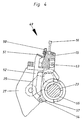
- the projectile weaving machine according to the invention shown in FIG. 1 has a left outer frame wall 2 carrying the weft mechanism 1 and a right outer frame wall 4 carrying the catch mechanism 3. Between these outer frame walls 2 and 4 there is a main drive 5 on the left and a further main drive 6 on the right side of the machine and between them, depending on the machine width, more than two middle frame walls 7.
- the outer frame walls 2 and 4 are connected to one another via tubular longitudinal connectors 8 and breast beam 9 and form the so-called frame.
- a chain 11 coming from a warp beam 10 is deflected over a coating tube 12, through heald eyes 13 of heald frames 14 through a reed 16 attached to a saddle carrier 15 and via a height-adjustable circular rail 17 onto the breast tube 9.
- the shedding is done by means of known dobby machines.
- the weft insertion at right angles to the warp thread direction creates the fabric or fabric formation in the front dead center position of the reed 16 at the front edge.
- the goods formed from here run over the round rail 17 and deflected through the breast tree tube 9 into the roller system of a fabric take-off, consisting of the rollers 18, 19, 20, 21 and the take-off gears 22 and is corresponding to the respective weft density deducted.
- the crankshaft 23, which swings back and forth over the entire weaving machine width, is supported on both sides between the chest boom tube 9 and the package of the shafts 14.
- crankshaft is shown in perspective in FIG. 3 with its drive.
- Crank arms 25 with pivot point 26a are rotatably articulated in the cranked portions 24 of crankshaft 23 and transmit the movements imposed on them at pivot point 26 to shop supports 27 which in turn move about pivot point 28 (FIG. 2).
- a weaving rack 15 (FIGS. 4 and 5) is fastened on the shop supports 27 and swings back and forth with it. During the rest in the rear dead center position of the sley 15, the weft is inserted and in the front dead center position the weft stop on the fabric edge. According to the embodiment, the crankshaft 23 is driven via the main gears 5 and 6 (FIG. 1), one of which is shown schematically in FIG. 3 without a housing.
- the preferably selected three-phase motor 29 transmits its movement via a V-belt pulley 30 and a V-belt drive 31 to a detachable drive pulley 32 which is arranged on the input drive shaft 33 of the main drive.
- the drive is carried out on cam disk wheel 37, which is connected to the complementary cam disk shaft 38, to the complementary cam disks 39 fastened thereon and 40, which in turn cause the toothed segment 41 to oscillate via the arms 42 and 42a located on the gear segment 41 and the cam rollers 43.
- the pendulum movement is transmitted to the crankshaft output point 45 via a wheel 44 which is in engagement with the toothed segment 41.
- the connection of the individual crank strokes in accordance with the modular design takes place by means of the shaft couplings 46.
- the synchronization of the main drives 5 and 6 arranged to the right and left of the machine center takes place via a synchronous shaft 47 running fast in relation to the camshaft shaft, which connects both transmissions 5 and 6 via coupling 48.
- FIGS. 4 and 5 show the sectional drawer 15 fastened over the entire weaving width and fastened to the shop supports 27 with the clamped reed 16.
- the weaving rack is also the basis for a projectile guide system 49, consisting of guide elements 50, a guide rail 1, a transmission lever 52 with its pivot points 53 and 54, and a bearing ring 55 for the pivot point 54 in plate 57, which is movably seated on the crankshaft 23.
- the bearing ring 55 is freely rotatable on the crankshaft 23.
- the guide system 49 with the guide elements 50 fastened to the guide carrier rail 51 extends over the entire weaving width. In the rear shop position shown as FIG. 4, the weft is inserted by means of projectile 56 (FIG. 9).
- the guide elements 50 it is necessary for the guide elements 50 to be absolutely congruent with the outlet channel of the firing unit 1 (FIG. 1). This is made kinematic by the Articulated arrangement of the guide system is achieved, wherein, in order to stabilize the end position of the guide elements 50, supporting legs of the guide support rail 51 are brought into abutment by means of spring means (not shown) on the surface of the tray 15 parallel to the leg.
- the sley carrier 15 After the weft has been inserted, which takes place when the sley is stationary, the sley carrier 15 now swings into the front dead center position shown as FIG. 5 and connects the weft thread.
- the projectile guidance system 49 with the guide elements 50 executes a relative movement to the sley 15 and the reed 16 by the arrangement of the articulation points 53 and 54 to the fulcrum of the crankshaft 53 such that the guide elements 50 are in the front dead center position before the reed 16 stops have inevitably moved out the lower compartment of the warp threads.
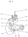
- FIG. 6 Another embodiment is shown in FIG. 6.
- Support bearings 79 and pivot points 73 for movement levers 75 are arranged on the weaving rack 15.
- a linear drive 77 is supported, which can consist, for example, of a piston-cylinder unit or a magnetic drive.
- drive 77 engages pivot point 76 of movement lever 75.
- the drives 77 Via a machine control, not shown, the drives 77 generate a lifting movement, which causes the guide elements 50, which are fixedly connected to the movement levers 75 via the guide support rail 51, to be in the shed at the time of the weft insertion and to be in place again after the weft entry before the loading stop move out of the shed.
- Figure 7 shows schematically the arrangement of the coupling means for the shooting and catching mechanism, by means of which they can be separated from the main drives.
- the main drives 5 and 6 each have an output shaft 60 and 61 which run at a speed ratio of 1: 1 to the crankshaft shaft 38 (FIG. 3).
- the rotary movement of the output shafts 60 and 61 is transmitted via coupling means 62 and 62a to the weft mechanism 1 via chain drives 63 and to the catching mechanism 3 via chain drive 64.
- Overload clutches 65 and 65a are preferably provided in this drive system.
- FIG. 8 shows an alternative embodiment as an example.
- the guide elements 50 are fixedly connected to the weaving rack 15 and arranged in a fixed position relative to the weaving reed 16.
- the shop supports 27 are moved back and forth about the pivot point 28 via the crankshaft 23 and crank arms 25 in the manner described.
- the pivot point 28 is located on a roller lever 66 which has its pivot point 67 in the bearing 68.
- the complementary cam 69 which is seated on a drive shaft 70, the shop support 27 with the elements 15, 16 and 50 attached to it is lowered so far after the weft insertion that the guide elements 50 are no longer in the area of the shed 13 at the shop stop.
- the shop support 27 with the elements 15, 16 and 50 attached to it is raised again accordingly.
- FIG. 9 schematically represents an embodiment variant in which the firing mechanism 1 and the catching mechanism 3 are fixed are connected to the weaving rack 15 and swing back and forth with it.
Landscapes
- Engineering & Computer Science (AREA)
- Textile Engineering (AREA)
- Looms (AREA)
Applications Claiming Priority (2)
| Application Number | Priority Date | Filing Date | Title |
|---|---|---|---|
| DE4308243 | 1993-03-11 | ||
| DE4308243A DE4308243A1 (de) | 1993-03-11 | 1993-03-11 | Projektil-Breitwebmaschine |
Publications (2)
| Publication Number | Publication Date |
|---|---|
| EP0615013A1 true EP0615013A1 (fr) | 1994-09-14 |
| EP0615013B1 EP0615013B1 (fr) | 1999-07-07 |
Family
ID=6482869
Family Applications (1)
| Application Number | Title | Priority Date | Filing Date |
|---|---|---|---|
| EP94101546A Expired - Lifetime EP0615013B1 (fr) | 1993-03-11 | 1994-02-02 | Métier à tisser en grande largeur à fausse navette |
Country Status (5)
| Country | Link |
|---|---|
| US (1) | US5505231A (fr) |
| EP (1) | EP0615013B1 (fr) |
| JP (1) | JPH073575A (fr) |
| CA (1) | CA2118554C (fr) |
| DE (2) | DE4308243A1 (fr) |
Cited By (1)
| Publication number | Priority date | Publication date | Assignee | Title |
|---|---|---|---|---|
| EP0922801A1 (fr) * | 1997-12-09 | 1999-06-16 | Sulzer Rüti Ag | Métier à tisser plus particulièrement métier à tisser en grande largeur |
Families Citing this family (4)
| Publication number | Priority date | Publication date | Assignee | Title |
|---|---|---|---|---|
| BE1015819A3 (nl) * | 2003-12-16 | 2005-09-06 | Wiele Michel Van De Nv | Aandrijfinrichting. |
| US7178558B2 (en) * | 2005-04-25 | 2007-02-20 | Massachusetts Institute Of Technology | Modular weaving for short production runs |
| US7318456B2 (en) * | 2005-04-25 | 2008-01-15 | Massachusetts Institute Of Technology | Modular weaving system with individual yarn control |
| JP4921747B2 (ja) * | 2005-09-09 | 2012-04-25 | 株式会社貝印刃物開発センター | 剃刀 |
Citations (12)
| Publication number | Priority date | Publication date | Assignee | Title |
|---|---|---|---|---|
| GB560993A (en) * | 1942-10-26 | 1944-05-01 | Brough Nicholson & Hall Ltd | Improvements in or relating to looms for weaving |
| US3110327A (en) * | 1962-05-16 | 1963-11-12 | Font Buenaventura Costa | Power loom |
| BE702866A (fr) * | 1966-09-06 | 1968-01-15 | ||
| FR2145493A1 (fr) * | 1971-07-13 | 1973-02-23 | Matthys Julien Et Fils | |
| FR2225555A1 (fr) * | 1973-04-10 | 1974-11-08 | Saurer Ag Adolph | |
| GB1483103A (en) * | 1974-11-13 | 1977-08-17 | Vyzk Vyvojovy Ustav Vseobe | Supporting means for a picking comb in a shuttleless loom |
| FR2505888A1 (fr) * | 1981-05-12 | 1982-11-19 | Alsacienne Constr Meca | Boite a cames pour machine a tisser |
| DE3242121A1 (de) * | 1982-11-13 | 1984-05-17 | Fa. F. Oberdorfer, 7920 Heidenheim | Webmaschine fuer siebe und filze zur ausruestung von papiermaschinen und dergleichen |
| DE3723433A1 (de) * | 1987-04-03 | 1988-10-20 | Textilma Ag | Bandwebmaschine |
| EP0298454A1 (fr) * | 1987-07-08 | 1989-01-11 | Nissan Motor Co., Ltd. | Système du mouvement du peigne d'une machine à tisser |
| EP0359940A2 (fr) * | 1988-09-20 | 1990-03-28 | F. Oberdorfer GmbH & Co. KG Industriegewebe-Technik | Guide-navette dans les métiers à tisser à plat pour tamis et feutres pour l'équipement des métiers à papier ou similaires |
| EP0521244A1 (fr) * | 1991-07-05 | 1993-01-07 | JÜRGENS MASCHINENBAU GMBH & CO. KG | Métier à tisser |
Family Cites Families (11)
| Publication number | Priority date | Publication date | Assignee | Title |
|---|---|---|---|---|
| US2793658A (en) * | 1954-08-31 | 1957-05-28 | George W Dunham | Lay and pilot guides |
| DE1535561B1 (de) * | 1964-12-01 | 1970-07-23 | Oberdorfer Metalltuchfabrik F | Verfahren zur Schuetzenfuehrung an Flachwebstuehlen |
| JPS5164059A (en) * | 1974-11-27 | 1976-06-03 | Vyzk Vyvojovy Ustav | Shatsutoru resuruumuno pitsukingu komushijisochi |
| DE2758454A1 (de) * | 1977-12-28 | 1979-07-05 | Girmes Werke Ag | Webblatt |
| US4473096A (en) * | 1979-08-06 | 1984-09-25 | Leesona Corporation | Weft end reception system |
| JPS56101949A (en) * | 1980-01-09 | 1981-08-14 | Nissan Motor | Shuttle striking apparatus of shuttleless loom having weft yarn guide element |
| CH645418A5 (de) * | 1980-03-27 | 1984-09-28 | Rueti Ag Maschf | Einrichtung zur fuehrung eines mittels eines stroemenden fluidums angetriebenen schussfadens im webfach einer webmaschine. |
| CH648616A5 (de) * | 1980-12-02 | 1985-03-29 | Sulzer Ag | Fuehrungszahn zur bildung eines schusseintragskanales einer webmaschine. |
| DE3325591C2 (de) * | 1983-07-15 | 1984-11-15 | Lindauer Dornier Gmbh, 8990 Lindau | Anordnung zur Entlastung der Antriebsmechanismen an Webmaschinen |
| EP0165327B1 (fr) * | 1984-06-19 | 1988-08-17 | GebràDer Sulzer Aktiengesellschaft | Dispositif de guidage pour l'inséreur de trame d'un métier à tisser, plus particulièrement d'un métier à tisser à navette à pince |
| EP0557723B1 (fr) * | 1992-02-28 | 1997-05-21 | Lindauer Dornier Gesellschaft M.B.H | Dispositif de guidage de bandes ou de lances d'insertion pour métiers à tisser |
-
1993
- 1993-03-11 DE DE4308243A patent/DE4308243A1/de not_active Ceased
-
1994
- 1994-02-02 EP EP94101546A patent/EP0615013B1/fr not_active Expired - Lifetime
- 1994-02-02 DE DE59408449T patent/DE59408449D1/de not_active Expired - Lifetime
- 1994-03-08 CA CA002118554A patent/CA2118554C/fr not_active Expired - Lifetime
- 1994-03-10 JP JP6038922A patent/JPH073575A/ja active Pending
- 1994-03-11 US US08/212,040 patent/US5505231A/en not_active Expired - Lifetime
Patent Citations (12)
| Publication number | Priority date | Publication date | Assignee | Title |
|---|---|---|---|---|
| GB560993A (en) * | 1942-10-26 | 1944-05-01 | Brough Nicholson & Hall Ltd | Improvements in or relating to looms for weaving |
| US3110327A (en) * | 1962-05-16 | 1963-11-12 | Font Buenaventura Costa | Power loom |
| BE702866A (fr) * | 1966-09-06 | 1968-01-15 | ||
| FR2145493A1 (fr) * | 1971-07-13 | 1973-02-23 | Matthys Julien Et Fils | |
| FR2225555A1 (fr) * | 1973-04-10 | 1974-11-08 | Saurer Ag Adolph | |
| GB1483103A (en) * | 1974-11-13 | 1977-08-17 | Vyzk Vyvojovy Ustav Vseobe | Supporting means for a picking comb in a shuttleless loom |
| FR2505888A1 (fr) * | 1981-05-12 | 1982-11-19 | Alsacienne Constr Meca | Boite a cames pour machine a tisser |
| DE3242121A1 (de) * | 1982-11-13 | 1984-05-17 | Fa. F. Oberdorfer, 7920 Heidenheim | Webmaschine fuer siebe und filze zur ausruestung von papiermaschinen und dergleichen |
| DE3723433A1 (de) * | 1987-04-03 | 1988-10-20 | Textilma Ag | Bandwebmaschine |
| EP0298454A1 (fr) * | 1987-07-08 | 1989-01-11 | Nissan Motor Co., Ltd. | Système du mouvement du peigne d'une machine à tisser |
| EP0359940A2 (fr) * | 1988-09-20 | 1990-03-28 | F. Oberdorfer GmbH & Co. KG Industriegewebe-Technik | Guide-navette dans les métiers à tisser à plat pour tamis et feutres pour l'équipement des métiers à papier ou similaires |
| EP0521244A1 (fr) * | 1991-07-05 | 1993-01-07 | JÜRGENS MASCHINENBAU GMBH & CO. KG | Métier à tisser |
Cited By (1)
| Publication number | Priority date | Publication date | Assignee | Title |
|---|---|---|---|---|
| EP0922801A1 (fr) * | 1997-12-09 | 1999-06-16 | Sulzer Rüti Ag | Métier à tisser plus particulièrement métier à tisser en grande largeur |
Also Published As
| Publication number | Publication date |
|---|---|
| DE4308243A1 (de) | 1994-09-15 |
| DE59408449D1 (de) | 1999-08-12 |
| CA2118554A1 (fr) | 1994-09-12 |
| CA2118554C (fr) | 1999-06-29 |
| US5505231A (en) | 1996-04-09 |
| JPH073575A (ja) | 1995-01-06 |
| EP0615013B1 (fr) | 1999-07-07 |
Similar Documents
| Publication | Publication Date | Title |
|---|---|---|
| EP0297586B1 (fr) | Machine Jacquard à double lève du type à foule ouverte | |
| DE10128538A1 (de) | Webmaschine zum Herstellen eines Drehergewebes | |
| EP0450120A1 (fr) | Procédé et dispositif de gaze pour la réalisation des fausses lisières d'un tissu double sur métier à doubles grittes | |
| DE3325591C2 (de) | Anordnung zur Entlastung der Antriebsmechanismen an Webmaschinen | |
| DE2616910A1 (de) | Vorrichtung zur bildung einer dreherbindungs-webkante auf webstuehlen | |
| DE1072569B (de) | Flachwebmaschine mit horizontalem Kettenfadenverl'auf sowie mit längs der Webbreite als Wanderwelle fortschreitender Fachbildung | |
| EP0615013A1 (fr) | Métier à tisser en grande largeur à fausse navette | |
| DE3044176C2 (de) | Vorrichtung an einer Frottier-Webmaschine zum Verändern der Anschlagstellungen des Webeblattes | |
| DE4404451C2 (de) | Dreherleistenvorrichtung | |
| EP0565934B1 (fr) | Métier à tisser modulaire | |
| DE1965832B2 (de) | Nadelwebmaschine | |
| DE3224708C2 (de) | Einrichtung zur zwangsläufigen Betätigung der Klemmvorrichtung von Schußfadeneintragorganen an schützenlosen Webmaschinen | |
| DE2153243C3 (de) | Schützenlose Webmaschine für Doppelflorgewebe | |
| DE3205227A1 (de) | Schuetzenlose doppelwebmaschine mit doppelgreifern | |
| DE4237744C1 (de) | Verfahren und Vorrichtung zum Entkuppeln des Antriebes von Greifern an Greiferwebmaschinen | |
| DE2248849A1 (de) | Webmaschine oder webstuhl | |
| DE370915C (de) | Webstuhl mit senkrecht verlaufender Webkette, insbesondere zum Weben von Baendern und aehnlichen Stoffbahnen | |
| DE7520574U (de) | Doppelplüsch-Webmaschine mit Entnahme der Schuß- und Polfäden von ortsfesten Spulen | |
| DE2153243B2 (de) | Schützenlose Webmaschine für Doppelflorgewebe | |
| DE1949300C (fr) | ||
| DE1059849B (de) | Schuetzenlose Flachwebmaschine | |
| DE1535393C (de) | Vorrichtung fur Webmaschinen zum Herstellen einer aus zwei Dreherfaden und einem Bindefaden bestehenden Dreher kante | |
| DE1535810C (de) | Drahtwebmaschine mit den Schußdraht haltenden und ihn m das Fach einfuhren den Schiebern | |
| EP0467824A1 (fr) | Métier à tisser avec un dispositif changeur de trame | |
| DE1535337C (de) | Antrieb für zwei auf beiden Seiten einer Bandwebmaschine für zwei nebeneinander herzustellende Gewebe vorgesehene Eintragnadeln |
Legal Events
| Date | Code | Title | Description |
|---|---|---|---|
| PUAI | Public reference made under article 153(3) epc to a published international application that has entered the european phase |
Free format text: ORIGINAL CODE: 0009012 |
|
| AK | Designated contracting states |
Kind code of ref document: A1 Designated state(s): BE DE FR GB IT NL SE |
|
| 17P | Request for examination filed |
Effective date: 19941216 |
|
| 17Q | First examination report despatched |
Effective date: 19950324 |
|
| GRAG | Despatch of communication of intention to grant |
Free format text: ORIGINAL CODE: EPIDOS AGRA |
|
| GRAG | Despatch of communication of intention to grant |
Free format text: ORIGINAL CODE: EPIDOS AGRA |
|
| GRAG | Despatch of communication of intention to grant |
Free format text: ORIGINAL CODE: EPIDOS AGRA |
|
| GRAH | Despatch of communication of intention to grant a patent |
Free format text: ORIGINAL CODE: EPIDOS IGRA |
|
| GRAH | Despatch of communication of intention to grant a patent |
Free format text: ORIGINAL CODE: EPIDOS IGRA |
|
| ITF | It: translation for a ep patent filed |
Owner name: KARAGHIOSOFF GIORGIO |
|
| GRAA | (expected) grant |
Free format text: ORIGINAL CODE: 0009210 |
|
| AK | Designated contracting states |
Kind code of ref document: B1 Designated state(s): BE DE FR GB IT NL SE |
|
| REF | Corresponds to: |
Ref document number: 59408449 Country of ref document: DE Date of ref document: 19990812 |
|
| ET | Fr: translation filed | ||
| GBT | Gb: translation of ep patent filed (gb section 77(6)(a)/1977) |
Effective date: 19990914 |
|
| RAP2 | Party data changed (patent owner data changed or rights of a patent transferred) |
Owner name: JUERGENS GMBH & CO. |
|
| NLT2 | Nl: modifications (of names), taken from the european patent patent bulletin |
Owner name: JUERGENS GMBH & CO. |
|
| PLBE | No opposition filed within time limit |
Free format text: ORIGINAL CODE: 0009261 |
|
| STAA | Information on the status of an ep patent application or granted ep patent |
Free format text: STATUS: NO OPPOSITION FILED WITHIN TIME LIMIT |
|
| 26N | No opposition filed | ||
| NLS | Nl: assignments of ep-patents |
Owner name: JUERGENS GMBH & CO. |
|
| REG | Reference to a national code |
Ref country code: GB Ref legal event code: IF02 |
|
| PGFP | Annual fee paid to national office [announced via postgrant information from national office to epo] |
Ref country code: IT Payment date: 20120223 Year of fee payment: 19 |
|
| PGFP | Annual fee paid to national office [announced via postgrant information from national office to epo] |
Ref country code: GB Payment date: 20130219 Year of fee payment: 20 Ref country code: SE Payment date: 20130219 Year of fee payment: 20 Ref country code: FR Payment date: 20130315 Year of fee payment: 20 |
|
| PGFP | Annual fee paid to national office [announced via postgrant information from national office to epo] |
Ref country code: NL Payment date: 20130218 Year of fee payment: 20 Ref country code: BE Payment date: 20130218 Year of fee payment: 20 |
|
| PGFP | Annual fee paid to national office [announced via postgrant information from national office to epo] |
Ref country code: DE Payment date: 20130409 Year of fee payment: 20 |
|
| REG | Reference to a national code |
Ref country code: DE Ref legal event code: R071 Ref document number: 59408449 Country of ref document: DE |
|
| REG | Reference to a national code |
Ref country code: NL Ref legal event code: V4 Effective date: 20140202 |
|
| REG | Reference to a national code |
Ref country code: GB Ref legal event code: PE20 Expiry date: 20140201 |
|
| BE20 | Be: patent expired |
Owner name: *JURGENS MASCHINENBAU G.M.B.H. & CO. K.G. Effective date: 20140202 |
|
| REG | Reference to a national code |
Ref country code: SE Ref legal event code: EUG |
|
| PG25 | Lapsed in a contracting state [announced via postgrant information from national office to epo] |
Ref country code: DE Free format text: LAPSE BECAUSE OF EXPIRATION OF PROTECTION Effective date: 20140204 Ref country code: GB Free format text: LAPSE BECAUSE OF EXPIRATION OF PROTECTION Effective date: 20140201 |