EP0615013A1 - Wide, dummy shuttle loom - Google Patents
Wide, dummy shuttle loom Download PDFInfo
- Publication number
- EP0615013A1 EP0615013A1 EP94101546A EP94101546A EP0615013A1 EP 0615013 A1 EP0615013 A1 EP 0615013A1 EP 94101546 A EP94101546 A EP 94101546A EP 94101546 A EP94101546 A EP 94101546A EP 0615013 A1 EP0615013 A1 EP 0615013A1
- Authority
- EP
- European Patent Office
- Prior art keywords
- sley
- guide elements
- weaving
- wide
- machine according
- Prior art date
- Legal status (The legal status is an assumption and is not a legal conclusion. Google has not performed a legal analysis and makes no representation as to the accuracy of the status listed.)
- Granted
Links
Images


Classifications
-
- D—TEXTILES; PAPER
- D03—WEAVING
- D03D—WOVEN FABRICS; METHODS OF WEAVING; LOOMS
- D03D47/00—Looms in which bulk supply of weft does not pass through shed, e.g. shuttleless looms, gripper shuttle looms, dummy shuttle looms
- D03D47/12—Looms in which bulk supply of weft does not pass through shed, e.g. shuttleless looms, gripper shuttle looms, dummy shuttle looms wherein single picks of weft thread are inserted, i.e. with shedding between each pick
- D03D47/24—Looms in which bulk supply of weft does not pass through shed, e.g. shuttleless looms, gripper shuttle looms, dummy shuttle looms wherein single picks of weft thread are inserted, i.e. with shedding between each pick by gripper or dummy shuttle
-
- D—TEXTILES; PAPER
- D03—WEAVING
- D03D—WOVEN FABRICS; METHODS OF WEAVING; LOOMS
- D03D49/00—Details or constructional features not specially adapted for looms of a particular type
- D03D49/60—Construction or operation of slay
Definitions
- the invention relates to a wide weaving machine, in particular for the production of flat woven paper machine clothing or other technical fabrics with warp and weft threads, preferably with widths of more than 6 m, with a weaving sway oscillating in the direction of the warp threads, and a method for moving guide elements for Projectiles on wide weaving machines with swinging sley.
- Weaving machines for the production of flat-woven paper machine clothing or similar technical fabrics which are manufactured in widths of 6 - 12 m with high warp tensions and shop slinging forces of up to 5 to / m weaving width, are special weaving machines and cannot be compared with the category of textile weaving machines.
- Characteristic of the textile weaving machines are their narrow weaving width, their high number of wefts per minute and their light construction adapted to these conditions, which is made clear by the drive of the sley, which is usual with these looms, by means of an oscillating shaft on which the shop supports carrying the sley sit and synchronize with it move. In these machines, this oscillating shaft is driven by a cam mechanism (FIG. 10).
- weft insertion is currently carried out by means of so-called rapier weavers, which in terms of their dimensions and their mass - which not only accelerate but also have to be brought to a standstill safely and accurately - larger weft numbers not allow.
- the unstable rifle flight also limited the rifle speeds and thus the performance increase of these machines.
- the invention is therefore based on the object of designing a wide weaving machine which eliminates the aforementioned disadvantages which have hitherto hindered an increase in performance in these special weaving machines.
- a second movement is superimposed on the guide elements.
- the guide elements which are necessary for guiding the projectiles, emerge from the compartment after the weft entry and thus no longer interfere with the striking of the reed against the fabric edge.
- it is therefore a movement component which is superimposed essentially in the direction perpendicular to the warp threads in addition to the usual weaving movement, which takes place essentially in the direction of the warp threads on a circular arc.
- This movement which additionally causes the guide elements to emerge from the compartment, can be achieved by superimposing a second movement on the sley. If the sley also moves synchronously in the vertical direction, the guide elements can be firmly attached to the sley so that they do not have to move relative to the sley.
- the additional movement component can also be impressed, despite the higher mass of the sley, if the guide elements are firmly attached to the sley, the sley being designed to be pivotable about a fulcrum, which is itself pivoted on a lever with a fixed fulcrum, the lever is preferably designed to be driven by a cam.
- the drive shaft is designed as a crankshaft with connecting rods as a drive for the sley and preferably has bearing rings for the guide carrier rail.
- the guide support rail thus has a pivot point on the sley and is connected via a joint to a bearing ring which can be freely rotated on the crankshaft and which serves as a fixed attachment point.
- the sley has a reed, which is arranged at a front reversal point of the sley perpendicular to the center shed plane. The stop therefore takes place in the direction of the warp threads.
- the sley has more than two drawer supports, the drawer supports being part of a kinematic quadrilateral joint in the drive mechanism are arranged with crankshaft.
- cam disk drives are provided as the drive for the crankshaft, which are preferably arranged symmetrically to the machine center, in particular are designed as complementary cam disk drives, the machine can be built in the required width without the movements being precise due to torsion of the crankshaft, which are preferably arranged symmetrically to the machine center, in particular are designed as complementary cam disk drives, the machine can be built in the required width without the movements being precise due to torsion of the crankshaft, which are preferably arranged symmetrically to the machine center, in particular are designed as complementary cam disk drives, the machine can be built in the required width without the movements being precise due to torsion of the crankshaft, which are preferably arranged symmetrically to the machine center, in particular are designed as complementary cam disk drives, the machine can be built in the required width without the movements being precise due to torsion of the crankshaft, which are preferably arranged symmetrically to the machine center, in particular are designed as complementary cam disk drives, the machine can be built in the required width without the movements being precise due to torsion of
- the measure that the movements of the sley and the guide elements are designed to be mechanically synchronized also serves to precisely control the time of the different movements, in particular one connecting the drives to synchronize the cam mechanism Synchronous shaft is provided.
- the movement of the guide elements is derived mechanically, preferably by means of a joint system, from the movement of the sley.
- the guide elements can be articulated via a lever system on the one hand at a pivot point which is fixed relative to the machine frame and on the other hand at a second pivot point which moves with the sley. The drive is thus carried out via the sley.
- the weaving machine can be separated from the weft and catch mechanism by means of a coupling and is designed to be able to reverse.
- the fabric is moved in the reverse movement sequence without weft insertion in the direction opposite to the weaving direction.
- linear drives in particular piston-cylinder units, can advantageously be provided as a drive for the superimposed movement.
- weft and catch mechanism is designed to swing with the sley.
- the procedural task is solved in that a second movement is additionally superimposed on the guide elements.
- This method makes it possible to provide the weaving movement independently of the required movement of the guide elements.
- the amplitude of the weaving movement can thus be kept as small as possible, which is the same
- the direction of the stop can be designed independently of the exchange movement of the guide elements.
- the stop is in the direction of the warp threads. In this case, the stop at a reed directed perpendicular to the plane of the warp threads takes place relatively close to its clamping point, so that the high stop forces can be controlled by the short clamping length of the reed.
- the method according to the invention can also be implemented by superimposing a second movement on the sley.
- the guide elements can then be firmly attached to the sley.
- the masses to be moved in wide weaving machines can be reduced if the otherwise large and bulky guideways for guiding the rapier shooters are replaced by guide elements for projectiles by using projectile weft and catch mechanisms on wide weaving machines of a width of more than 6 m.
- FIG. 10 first shows a typical shop drive for unprotected textile weaving machines.
- the reed a and the guide teeth b are fastened together to a drawer c, which extends across the entire weaving machine width.
- the load carrier c is firmly connected to the multiple supports d, which in turn are all firmly connected to the oscillating shaft e.
- the projectile weaving machine according to the invention shown in FIG. 1 has a left outer frame wall 2 carrying the weft mechanism 1 and a right outer frame wall 4 carrying the catch mechanism 3. Between these outer frame walls 2 and 4 there is a main drive 5 on the left and a further main drive 6 on the right side of the machine and between them, depending on the machine width, more than two middle frame walls 7.
- the outer frame walls 2 and 4 are connected to one another via tubular longitudinal connectors 8 and breast beam 9 and form the so-called frame.
- a chain 11 coming from a warp beam 10 is deflected over a coating tube 12, through heald eyes 13 of heald frames 14 through a reed 16 attached to a saddle carrier 15 and via a height-adjustable circular rail 17 onto the breast tube 9.
- the shedding is done by means of known dobby machines.
- the weft insertion at right angles to the warp thread direction creates the fabric or fabric formation in the front dead center position of the reed 16 at the front edge.
- the goods formed from here run over the round rail 17 and deflected through the breast tree tube 9 into the roller system of a fabric take-off, consisting of the rollers 18, 19, 20, 21 and the take-off gears 22 and is corresponding to the respective weft density deducted.
- the crankshaft 23, which swings back and forth over the entire weaving machine width, is supported on both sides between the chest boom tube 9 and the package of the shafts 14.
- crankshaft is shown in perspective in FIG. 3 with its drive.
- Crank arms 25 with pivot point 26a are rotatably articulated in the cranked portions 24 of crankshaft 23 and transmit the movements imposed on them at pivot point 26 to shop supports 27 which in turn move about pivot point 28 (FIG. 2).
- a weaving rack 15 (FIGS. 4 and 5) is fastened on the shop supports 27 and swings back and forth with it. During the rest in the rear dead center position of the sley 15, the weft is inserted and in the front dead center position the weft stop on the fabric edge. According to the embodiment, the crankshaft 23 is driven via the main gears 5 and 6 (FIG. 1), one of which is shown schematically in FIG. 3 without a housing.
- the preferably selected three-phase motor 29 transmits its movement via a V-belt pulley 30 and a V-belt drive 31 to a detachable drive pulley 32 which is arranged on the input drive shaft 33 of the main drive.
- the drive is carried out on cam disk wheel 37, which is connected to the complementary cam disk shaft 38, to the complementary cam disks 39 fastened thereon and 40, which in turn cause the toothed segment 41 to oscillate via the arms 42 and 42a located on the gear segment 41 and the cam rollers 43.
- the pendulum movement is transmitted to the crankshaft output point 45 via a wheel 44 which is in engagement with the toothed segment 41.
- the connection of the individual crank strokes in accordance with the modular design takes place by means of the shaft couplings 46.
- the synchronization of the main drives 5 and 6 arranged to the right and left of the machine center takes place via a synchronous shaft 47 running fast in relation to the camshaft shaft, which connects both transmissions 5 and 6 via coupling 48.
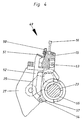
- FIGS. 4 and 5 show the sectional drawer 15 fastened over the entire weaving width and fastened to the shop supports 27 with the clamped reed 16.
- the weaving rack is also the basis for a projectile guide system 49, consisting of guide elements 50, a guide rail 1, a transmission lever 52 with its pivot points 53 and 54, and a bearing ring 55 for the pivot point 54 in plate 57, which is movably seated on the crankshaft 23.
- the bearing ring 55 is freely rotatable on the crankshaft 23.
- the guide system 49 with the guide elements 50 fastened to the guide carrier rail 51 extends over the entire weaving width. In the rear shop position shown as FIG. 4, the weft is inserted by means of projectile 56 (FIG. 9).
- the guide elements 50 it is necessary for the guide elements 50 to be absolutely congruent with the outlet channel of the firing unit 1 (FIG. 1). This is made kinematic by the Articulated arrangement of the guide system is achieved, wherein, in order to stabilize the end position of the guide elements 50, supporting legs of the guide support rail 51 are brought into abutment by means of spring means (not shown) on the surface of the tray 15 parallel to the leg.
- the sley carrier 15 After the weft has been inserted, which takes place when the sley is stationary, the sley carrier 15 now swings into the front dead center position shown as FIG. 5 and connects the weft thread.
- the projectile guidance system 49 with the guide elements 50 executes a relative movement to the sley 15 and the reed 16 by the arrangement of the articulation points 53 and 54 to the fulcrum of the crankshaft 53 such that the guide elements 50 are in the front dead center position before the reed 16 stops have inevitably moved out the lower compartment of the warp threads.
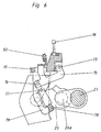
- FIG. 6 Another embodiment is shown in FIG. 6.
- Support bearings 79 and pivot points 73 for movement levers 75 are arranged on the weaving rack 15.
- a linear drive 77 is supported, which can consist, for example, of a piston-cylinder unit or a magnetic drive.
- drive 77 engages pivot point 76 of movement lever 75.
- the drives 77 Via a machine control, not shown, the drives 77 generate a lifting movement, which causes the guide elements 50, which are fixedly connected to the movement levers 75 via the guide support rail 51, to be in the shed at the time of the weft insertion and to be in place again after the weft entry before the loading stop move out of the shed.
- Figure 7 shows schematically the arrangement of the coupling means for the shooting and catching mechanism, by means of which they can be separated from the main drives.
- the main drives 5 and 6 each have an output shaft 60 and 61 which run at a speed ratio of 1: 1 to the crankshaft shaft 38 (FIG. 3).
- the rotary movement of the output shafts 60 and 61 is transmitted via coupling means 62 and 62a to the weft mechanism 1 via chain drives 63 and to the catching mechanism 3 via chain drive 64.
- Overload clutches 65 and 65a are preferably provided in this drive system.
- FIG. 8 shows an alternative embodiment as an example.
- the guide elements 50 are fixedly connected to the weaving rack 15 and arranged in a fixed position relative to the weaving reed 16.
- the shop supports 27 are moved back and forth about the pivot point 28 via the crankshaft 23 and crank arms 25 in the manner described.
- the pivot point 28 is located on a roller lever 66 which has its pivot point 67 in the bearing 68.
- the complementary cam 69 which is seated on a drive shaft 70, the shop support 27 with the elements 15, 16 and 50 attached to it is lowered so far after the weft insertion that the guide elements 50 are no longer in the area of the shed 13 at the shop stop.
- the shop support 27 with the elements 15, 16 and 50 attached to it is raised again accordingly.
- FIG. 9 schematically represents an embodiment variant in which the firing mechanism 1 and the catching mechanism 3 are fixed are connected to the weaving rack 15 and swing back and forth with it.
Abstract
Description
Die Erfindung betrifft eine Breitwebmaschine, insbesondere für die Herstellung flachgewebter Papiermaschinenbespannungen oder anderer technischer Gewebe mit Kett- und Schußfäden, vorzugsweise mit Breiten von mehr als 6 m, mit einer in Richtung der Kettfäden hin- und herschwingenden Weblade sowie ein Verfahren zum Bewegen von Führungselementen für Projektile an Breitwebmaschinen mit schwingender Weblade.The invention relates to a wide weaving machine, in particular for the production of flat woven paper machine clothing or other technical fabrics with warp and weft threads, preferably with widths of more than 6 m, with a weaving sway oscillating in the direction of the warp threads, and a method for moving guide elements for Projectiles on wide weaving machines with swinging sley.
Webmaschinen zur Herstellung von flachgewebten Papiermaschinenbespannungen oder ähnlichen technischen Geweben, die in Breiten von 6 - 12 m mit hohen Kettspannungen und Ladenanschlägkräften bis zu 5 to/m Webbreite hergestellt werden, sind Spezialwebmaschinen und mit der Gattung der Textilwebmaschinen nicht vergleichbar. Kennzeichen der Textilwebmaschinen sind ihre schmale Webbreite, ihre hohe Schußzahl pro Minute und ihre diesen Bedingungen angepaßte leichte Bauweise, was verdeutlicht wird durch den bei diesen Webmaschinen üblichen Antrieb der Weblade durch eine Schwingwelle, auf der die die Weblade tragenden Ladenstützen sitzen und sich mit dieser winkelsynchron bewegen. Der Antrieb dieser Schwingwelle erfolgt bei diesen Maschinen über ein Kurvengetriebe (Figur 10). Während die vorbeschriebenen Spezialwebmaschinen entsprechend dem derzeitigen Stand der Technik mit einer Schußzahl von ca. 50 Schuß/min. arbeiten, laufen die Textilwebmaschinen mit mechanischem Schußeintrag mehrere 100 Schuß/min. und Webmaschinen mit pneumatischem Schußeintrag sogar bis zu 1000 Schuß/min. und mehr.Weaving machines for the production of flat-woven paper machine clothing or similar technical fabrics, which are manufactured in widths of 6 - 12 m with high warp tensions and shop slinging forces of up to 5 to / m weaving width, are special weaving machines and cannot be compared with the category of textile weaving machines. Characteristic of the textile weaving machines are their narrow weaving width, their high number of wefts per minute and their light construction adapted to these conditions, which is made clear by the drive of the sley, which is usual with these looms, by means of an oscillating shaft on which the shop supports carrying the sley sit and synchronize with it move. In these machines, this oscillating shaft is driven by a cam mechanism (FIG. 10). While the above-described special weaving machines according to the current state of the art with a number of weft of about 50 wefts / min. work, the textile weaving machines run with mechanical weft insertion several 100 weft / min. and weaving machines with pneumatic weft insertion even up to 1000 weft / min. and more.
Ein wesentlicher Grund für die relativ geringen Schußzahlen bei den Spezialwebmaschinen liegt darin, daß der Schußeintrag derzeit mittels sogenannter Greiferwebschützen erfolgt, die von ihren Abmessungen und ihrer Masse her - die nicht nur beschleunigt, sondern auch sicher und positionsgenau zum Stehen gebracht werden müssen - größere Schußzahlen nicht ermöglichen.An important reason for the relatively low number of wefts in the special weaving machines is that the weft insertion is currently carried out by means of so-called rapier weavers, which in terms of their dimensions and their mass - which not only accelerate but also have to be brought to a standstill safely and accurately - larger weft numbers not allow.
Es ist deshalb auch versucht worden, die Greiferwebschützen zu miniaturisieren. Diese Maßnahmen wurden aber dadurch begrenzt, daß diese in ihren Abmessungen und gewichtsreduzierten Greiferschützen, welche ungeführt durch das Webfach geschossen wurden, instabil waren und in Extremfällen aus dem Webfach flogen.Attempts have therefore also been made to miniaturize the rapier shooters. However, these measures were limited by the fact that their dimensions and weight-reduced gripper shooters, which were shot through the shed without guidance, were unstable and in extreme cases flew out of the shed.
Ein Ausführungsbeispiel eines miniaturisierten Greiferwebschützen ist durch die deutsche Schrift DT 15 35 561 beschrieben worden.An embodiment of a miniaturized rifle shooter has been described by the
Der instabile Schützenflug begrenzte aber auch hier die Schützengeschwindigkeiten und damit die Leistungssteigerung dieser Maschinen.The unstable rifle flight also limited the rifle speeds and thus the performance increase of these machines.
Aus der deutschen Patentschrift DE-A1 32 42 121 ist unter anderem ersichtlich, daß die Nachteile des instabilen Schützenlaufs erfindungsgemäß dadurch beseitigt werden sollen, daß Führungselemente für den Webschützen vorgesehen wurden. Wenngleich auch mit dieser Maßnahme das Herausfliegen des Webschützen beseitigt werden konnte, haften diesem System aber noch Nachteile dergestalt an, daß der Webschützen auf den Kettfäden des Unterfachs, das sich auf der Weblade abstützt, entlangrollt. Dies wirkt sich im Falle eines unsauberen Unterfachs oder bei Überpackung der Weblade, d.h. wenn nicht alle Kettfäden des Unterfaches einwandfrei nebeneinander, sondern teilweise übereinander liegen, stark bremsend auf den Webschützen aus und beeinträchtigt damit ebenfalls die Leistungssteigerung.From the German patent DE-A1 32 42 121 it can be seen, inter alia, that the disadvantages of the unstable rifle barrel are to be eliminated according to the invention by providing guide elements for the shooter. Although this measure also prevented the shooter from flying out, there are still disadvantages to this system in that the shooter rolls along the warp threads of the lower shed, which is supported on the sley. This affects in the case of a dirty sub-compartment or when the weaving drawer is overpacked, ie if not all of the warp threads of the sub-compartment lie perfectly next to each other, but partly one above the other, brakes heavily on the shooters and thus also impairs the increase in performance.
Der Erfindung liegt daher die Aufgabe zugrunde, eine Breitwebmaschine zu gestalten, die die vorerwähnten Nachteile, die einer Leistungssteigerung bei diesen Spezialwebmaschinen bisher entgegenstanden, beseitigt.The invention is therefore based on the object of designing a wide weaving machine which eliminates the aforementioned disadvantages which have hitherto hindered an increase in performance in these special weaving machines.
Die Lösung dieser Aufgabe erfolgte durch die Maßnahme, daß ein Schuß- und ein Fangwerk für Projektile sowie Führungselemente zur Führung der Projektile vorgesehen sind, wobei die Führungselemente sich synchron mit der Weblade bewegend ausgebildet sind. Überraschenderweise kann auf der Grundlage eines von Textilwebmaschinen her bekannten Schußeintragssystems auch bei Breitwebmaschinen eine Leistungssteigerung erreicht werden.This problem was solved by the measure that a shot and catch mechanism for projectiles and guide elements for guiding the projectiles are provided, the guide elements being designed to move synchronously with the sley. Surprisingly, on the basis of a weft insertion system known from textile weaving machines, an increase in performance can also be achieved with wide weaving machines.
In Ausgestaltung der Erfindung ist vorgesehen, daß den Führungselementen eine zweite Bewegung überlagert ist. Dadurch tauchen die Führungselemente, die zur Führung der Projektile notwendig sind, nach dem Schußeintrag aus dem Fach aus und stören somit das Anschlagen des Webblattes an die Gewebekante nicht mehr. Es handelt sich in diesem Zusammenhang also um eine Bewegungskomponente, die im wesentlichen in senkrechter Richtung zu den Kettfäden überlagert wird zusätzlich zur üblichen Webladenbewegung, die im wesentlichen in Richtung der Kettfäden auf einem Kreisbogen erfolgt.In an embodiment of the invention it is provided that a second movement is superimposed on the guide elements. As a result, the guide elements, which are necessary for guiding the projectiles, emerge from the compartment after the weft entry and thus no longer interfere with the striking of the reed against the fabric edge. In this context, it is therefore a movement component which is superimposed essentially in the direction perpendicular to the warp threads in addition to the usual weaving movement, which takes place essentially in the direction of the warp threads on a circular arc.
Diese Bewegung, die ein Austreten der Führungselemente aus dem Fach zusätzlich bewirkt, kann dadurch verwirklicht werden, daß der Weblade eine zweite Bewegung überlagert ist. Wenn die Weblade sich zusätzlich in senkrechter Richtung synchron bewegt, können die Führungselemente fest an der Weblade montiert werden, so daß sie keine Relativbewegung zur Weblade vollführen müssen.This movement, which additionally causes the guide elements to emerge from the compartment, can be achieved by superimposing a second movement on the sley. If the sley also moves synchronously in the vertical direction, the guide elements can be firmly attached to the sley so that they do not have to move relative to the sley.
Die Massen, die bei dieser zusätzlichen Bewegungskomponente beschleunigt und wieder verzögert werden müssen, werden vorteilhaft verringert, wenn die Führungselemente an einer Führungsschiene befestigt sind, die um einen Drehpunkt schwenkbar ist, der an der Weblade angeordnet ist.The masses which have to be accelerated and decelerated again with this additional movement component are advantageously reduced if the guide elements are fastened to a guide rail which can be pivoted about a pivot point which is arranged on the sley.
Konstruktiv läßt sich auch die zusätzliche Bewegungskomponente trotz der höheren Massen der Weblade aufprägen, wenn die Führungselemente fest an der Weblade befestigt sind, wobei die Weblade schwenkbar um einen Drehpunkt ausgebildet ist, der selbst an einem Hebel mit ortsfestem Drehpunkt schwenkbar angelenkt ist, wobei der Hebel vorzugsweise von einer Kurvenscheibe angetrieben ausgebildet ist.In terms of design, the additional movement component can also be impressed, despite the higher mass of the sley, if the guide elements are firmly attached to the sley, the sley being designed to be pivotable about a fulcrum, which is itself pivoted on a lever with a fixed fulcrum, the lever is preferably designed to be driven by a cam.
Die erforderliche Präzision im Zusammenspiel der verschiedenen Bewegungskomponenten läßt sich am günstigsten dann erreichen, wenn die überlagerten Bewegungen von einer gemeinsamen Antriebswelle abgeleitet ausgebildet sind.The required precision in the interaction of the various movement components can be achieved most favorably if the superimposed movements are designed to be derived from a common drive shaft.
Dies läßt sich dadurch verwirklichen, indem die Antriebswelle als Kurbelwelle mit Pleueln als Antrieb für die Weblade ausgebildet ist und vorzugsweise Lagerringe für die Führungsträgerschiene aufweist. Die Führungsträgerschiene hat somit einen Anlenkpunkt an der Weblade und ist über ein Gelenk mit einem auf der Kurbelwelle frei drehbaren Lagerring verbunden, der als ortsfester Anschlagpunkt dient.This can be achieved in that the drive shaft is designed as a crankshaft with connecting rods as a drive for the sley and preferably has bearing rings for the guide carrier rail. The The guide support rail thus has a pivot point on the sley and is connected via a joint to a bearing ring which can be freely rotated on the crankshaft and which serves as a fixed attachment point.
Damit die Qualität des Gewebes verbessert wird, ist vorgesehen, daß die Weblade ein Webblatt aufweist, welches in einem vorderen Umkehrpunkt der Weblade senkrecht zur MIttelfachebene angeordnet ist. Der Anschlag erfolgt also in Richtung der Kettfäden.So that the quality of the fabric is improved, it is provided that the sley has a reed, which is arranged at a front reversal point of the sley perpendicular to the center shed plane. The stop therefore takes place in the direction of the warp threads.
Um den mechanischen Problemen, die infolge der großen Webbreiten, hohen Anschlagkräften, großen zu beschleunigenden und zu verzögernden Massen entstehen, beherrschen zu können, ist es vorteilhaft, wenn die Weblade mehr als zwei Ladenstützen aufweist, wobei die Ladenstützen als Teil eines kinematischen Gelenkvierecks im Ladenantrieb mit Kurbelwelle angeordnet sind.In order to be able to master the mechanical problems that arise as a result of the large weaving widths, high lifting forces, large masses to be accelerated and decelerated, it is advantageous if the sley has more than two drawer supports, the drawer supports being part of a kinematic quadrilateral joint in the drive mechanism are arranged with crankshaft.
Dadurch, daß als Antrieb der Kurbelwelle ein oder mehrere Kurvenscheibengetriebe vorgesehen sind, die vorzugsweise symmetrisch zur Maschinenmitte angeordnet, insbesondere als Komplementärkurvenscheibengetriebe ausgebildet sind, kann die Maschine in der erforderlichen Breite gebaut werden, ohne daß die Bewegungen an Präzision durch Torsion derCharacterized in that one or more cam disk drives are provided as the drive for the crankshaft, which are preferably arranged symmetrically to the machine center, in particular are designed as complementary cam disk drives, the machine can be built in the required width without the movements being precise due to torsion of the
Antriebswellen leiden. Der präzisen zeitlichen Steuerung der unterschiedlichen Bewegungen dient auch die Maßnahme, daß die Bewegungen der Weblade und der Führungselemente mechanisch synchronisiert ausgebildet sind, wobei zur Synchronisierung der Kurvenscheibengetriebe insbesondere eine die Antriebe verbindende Synchronwelle vorgesehen ist.Drive shafts suffer. The measure that the movements of the sley and the guide elements are designed to be mechanically synchronized also serves to precisely control the time of the different movements, in particular one connecting the drives to synchronize the cam mechanism Synchronous shaft is provided.
Demselben Zweck dient es, wenn die Bewegung der Führungselemente mechanisch, vorzugsweise mittels eines Gelenksystems, von der Bewegung der Weblade abgeleitet ist. Dazu können die Führungselemente über ein Hebelsystem einerseits an einem relativ zum Maschinengestell festen Schwenkpunkt und an einem zweiten sich mit der Weblade bewegenden Schwenkpunkt andererseits angelenkt sein. Der Antrieb erfolgt somit über die Weblade.It serves the same purpose if the movement of the guide elements is derived mechanically, preferably by means of a joint system, from the movement of the sley. For this purpose, the guide elements can be articulated via a lever system on the one hand at a pivot point which is fixed relative to the machine frame and on the other hand at a second pivot point which moves with the sley. The drive is thus carried out via the sley.
Zur Behebung von Fehlern und zum bandenfreien Anweben ist es von Vorteil, wenn die Webmaschine von Schuß- und Fangwerk mittels einer Kupplung getrennt werden kann und rücklauffähig ausgebildet ist. Dabei wird in umgekehrter Bewegungsfolge jedoch ohne Schußeintrag das Gewebe in zur Webrichtung umgekehrter Richtung bewegt.In order to correct errors and for band-free weaving, it is advantageous if the weaving machine can be separated from the weft and catch mechanism by means of a coupling and is designed to be able to reverse. In this case, the fabric is moved in the reverse movement sequence without weft insertion in the direction opposite to the weaving direction.
Insbesondere für die Bewegung der Führungselemente können mit Vorteil als Antrieb für die überlagerte Bewegung Linearantriebe vorgesehen werden, insbesondere Kolben-Zylinder-Einheiten.In particular for the movement of the guide elements, linear drives, in particular piston-cylinder units, can advantageously be provided as a drive for the superimposed movement.
In weiterer Ausgestaltung der Erfindung ist vorgesehen, daß das Schuß- und Fangwerk mit der Weblade schwingend ausgebildet ist.In a further embodiment of the invention it is provided that the weft and catch mechanism is designed to swing with the sley.
Die Verfahrensaufgabe wird dadurch gelöst, daß den Führungselementen zusätzlich eine zweite Bewegung überlagert wird. Dieses Verfahren ermöglicht es, die Webladenbewegung unabhängig von der erforderlichen Austauchbewegung der Führungselemente vorzusehen. Die Webladenbewegung kann also in ihrer Amplitude so klein wie möglich gehalten werden, was bei gleicherThe procedural task is solved in that a second movement is additionally superimposed on the guide elements. This method makes it possible to provide the weaving movement independently of the required movement of the guide elements. The amplitude of the weaving movement can thus be kept as small as possible, which is the same
Produktivität, d.h. gleicher Schußzahl, geringere Beschleunigungen und Verzögerungen der beteiligten Massen bedeutet. Die auf die Maschine wirkenden Massenkräfte werden folglich verringert, was einen insgesamt ruhigeren Maschinenlauf ergibt. Andererseits kann bei gleicher Belastung die Schußzahl entsprechend erhöht werden, so daß die Produktivität verbessert wird. Schließlich kann die Richtung des Anschlags unabhängig von der Austauchbewegung der Führungselemente gestaltet werden. Der Anschlag erfolgt in Richtung der Kettfäden. Dabei erfolgt der Anschlag bei einem senkrecht zur Ebene der Kettfäden gerichteten Webblatt relativ nahe an seiner Einspannstelle, so daß die hohen Anschlagkräfte durch die kurze Einspannlänge des Webblattes beherrschbar sind.Productivity, i.e. same number of shots, lower accelerations and decelerations of the masses involved. The mass forces acting on the machine are consequently reduced, which results in an overall smoother machine run. On the other hand, with the same load, the number of shots can be increased accordingly, so that productivity is improved. Finally, the direction of the stop can be designed independently of the exchange movement of the guide elements. The stop is in the direction of the warp threads. In this case, the stop at a reed directed perpendicular to the plane of the warp threads takes place relatively close to its clamping point, so that the high stop forces can be controlled by the short clamping length of the reed.
Das erfindungsgemäße Verfahren läßt sich auch dadurch verwirklichen, daß der Weblade eine zweite Bewegung überlagert wird. Die Führungselemente können dann fest an der Weblade angebracht sein.The method according to the invention can also be implemented by superimposing a second movement on the sley. The guide elements can then be firmly attached to the sley.
Die bei Breitwebmaschinen zu bewegenden Massen können verringert werden, wenn durch Verwendung von Projektilschuß- und Fangwerken an Breitwebmaschinen von einer Breite von mehr als 6 m die sonst üblichen großen und massigen Führungsbahnen zur Führung der Greiferschützen durch Führungselemente für Projektile ersetzt werden.The masses to be moved in wide weaving machines can be reduced if the otherwise large and bulky guideways for guiding the rapier shooters are replaced by guide elements for projectiles by using projectile weft and catch mechanisms on wide weaving machines of a width of more than 6 m.
Weitere Vorteile, Einzelheiten und erfindungswesentliche Merkmale ergeben sich aus der nachfolgenden Beschreibung einer bevorzugten Ausführungsform der Erfindung unter Bezugnahme auf die beigefügten Figuren, wobei gleiche Teile mit denselben Bezugszeichen versehen worden sind.Further advantages, details and features essential to the invention result from the following description of a preferred embodiment of the invention with reference to the attached figures, the same parts being provided with the same reference numerals.
Im folgenden werden insbesondere die bevorzugten Ausführungsformen beschrieben.The preferred embodiments are described in particular below.
Es zeigen:
- Fig. 1
- eine Draufsicht auf eine Projektilwebmaschine mit den relevanten Einzelheiten und ihre Positionierung in schematischer Darstellung,
- Fig. 2
- einen Schnitt durch die erfindungsgemäße Projektilwebmaschine gemäß Schnittlinie II-II aus
Figur 1, - Fig. 3
- eine perspektivische Darstellung eines Antriebssystems für die Ladenbewegung
- Fig. 4
- eine Schnittzeichnung durch eine erfindungsgemäße Weblade mit Darstellung eines Projektilführungssystems in hinterer Totpunktlage,
- Fig. 5
- eine Schnittzeichnung durch die Weblade mit Darstellung des Projektilführungssystems in vorderer Totpunktlage,
- Fig. 6
- eine alternative Ausgestaltung eines Antriebs für die Führungselemente mittels elektrischer, pneumatischer oder hydraulischer Mittel,
- Fig. 7
- eine bevorzugte Anordnung der Kupplungsmittel für ein feststehendes Schuß- und Fangwerk,
- Fig. 8
- eine alternative Ausführungsform eines Antriebes für an der Weblade befestigte Projektilführungselemente,
- Fig. 9
- eine alternative Anordnung eines Schuß- und Fangwerkes, welches sich mit der Weblade bewegt und
- Fig. 10
- einen typischen Webladenantrieb für Textilmaschinen mit einer Schwingwelle und einem Kurvenscheibenantrieb in schematischer Darstellung.
- Fig. 1
- a plan view of a projectile weaving machine with the relevant details and their positioning in a schematic representation,
- Fig. 2
- 2 shows a section through the projectile weaving machine according to the invention along section line II-II from FIG. 1,
- Fig. 3
- a perspective view of a drive system for the shop movement
- Fig. 4
- 2 shows a sectional drawing through a weaving drawer according to the invention, showing a projectile guidance system in the rear dead center position,
- Fig. 5
- 2 shows a sectional drawing through the weaving shed showing the projectile guidance system in the front dead center position,
- Fig. 6
- an alternative embodiment of a drive for the guide elements by means of electrical, pneumatic or hydraulic means,
- Fig. 7
- a preferred arrangement of the coupling means for a fixed shooting and catching mechanism,
- Fig. 8
- an alternative embodiment of a drive for projectile guide elements attached to the sley,
- Fig. 9
- an alternative arrangement of a weft and catch mechanism, which moves with the sley and
- Fig. 10
- a typical weave drive for textile machines with an oscillating shaft and a cam drive in a schematic representation.
In Figur 10 ist zum besseren Verständnis des Unterschiedes zu Breitwebmaschinen zunächst ein typischer Ladenantrieb für schützenlose Textilwebmaschinen dargestellt.For a better understanding of the difference to wide weaving machines, FIG. 10 first shows a typical shop drive for unprotected textile weaving machines.
Das Webblatt a und die Führungszähne b sind gemeinsam an einen Ladenträger c, der über die gesamte Webmaschinenbreite geht, befestigt.The reed a and the guide teeth b are fastened together to a drawer c, which extends across the entire weaving machine width.
Der Ladenträger c ist fest verbunden mit den mehrfach vorhandenen Stützen d, die ihrerseits alle mit der Schwingwelle e fest verbunden sind.The load carrier c is firmly connected to the multiple supports d, which in turn are all firmly connected to the oscillating shaft e.
Über einen Kurvenscheibenantrieb f mit Drehpunkt in g und einem zweiarmigen Rollenhebel h, der ebenfalls fest mit der Schwingwelle e verbunden ist, wird der Schwingwelle e und den an ihr befestigten Elementen a, b, c und d eine winkelsynchrone Bewegung verliehen.Via a cam drive f with a fulcrum in g and a two-armed roller lever h, which is also firmly connected to the oscillating shaft e, the oscillating shaft e and the elements a, b, c and d attached to it are given an angularly synchronous movement.
Dieses relativ massenarme Ladenantriebssystem ist aus Gründen der wesentlich höheren Beanspruchungen bei Breitwebmaschinen und den hier erforderlichen erheblichen kinematischen Energien für den Ladenanschlag praktisch nicht anwendbar.This relatively low-mass shop drive system is due to the much higher demands on wide weaving machines and the considerable kinematic energies required here for the Shop stop practically not applicable.
Die in Figur 1 dargestellte erfindungsgemäße Projektilwebmaschine hat eine linke, das Schußwerk 1 tragende äußere Gestellwand 2 und eine rechte, das Fangwerk 3 tragende äußere Gestellwand 4. Zwischen diesen äußeren Gestellwänden 2 und 4 befinden sich ein Hauptantrieb 5 auf der linken und ein weiterer Hauptantrieb 6 auf der rechten Maschinenseite und zwischen diesen je nach Maschinenbreite mehr als zwei mittlere Gestellwände 7.The projectile weaving machine according to the invention shown in FIG. 1 has a left
Wie in Figur 2 erkennbar, sind die äußeren Gestellwände 2 und 4, die Hauptantriebe 5 und 6 sowie die mittleren Gestellwände 7 über modulmäßig ausgebildete Rohrlängsverbinder 8 und Brustbaum 9 miteinander verbunden und bilden das sogenannte Gestell.As can be seen in FIG. 2, the
Eine von einem Kettbaum 10 kommende Kette 11 läuft über ein Streichrohr 12 umgelenkt, durch Litzenaugen 13 von Webschäften 14 durch ein an einem Webladenträger 15 befestigtes Webblatt 16 und über eine höhenverstellbare Rundschiene 17 auf das Brustbaumrohr 9. Die Fachbildung geschieht mittels bekannter Schaftmaschinen. Durch den rechtwinklig zur Kettfadenrichtung erfolgten Schußeintrag entsteht in der vorderen Totpunktlage des Webblattes 16 an der Vorderkante die Gewebe bzw. Warenbildung.A
Die ab hier gebildete Ware läuft über die Rundschiene 17 und umgelenkt durch das Brustbaumrohr 9 in das Walzensystem eines Warenabzugs, bestehend aus den Walzen 18, 19, 20, 21 und den Abzugsgetrieben 22 und wird entsprechend der jeweiligen Schußdichte abgezogen. Die über die gesamte Webmaschinenbreite sich erstreckende, hin- und herschwingende Kurbelwelle 23 ist zwischen Brustbaumrohr 9 und dem Paket der Schäfte 14 beidseitig gelagert.The goods formed from here run over the
Die Kurbelwelle ist in Figur 3 perspektivisch mit ihrem Antrieb dargestellt. In den Kröpfungen 24 der Kurbelwelle 23 sind Kurbelarme 25 mit Drehpunkt 26a drehbar angelenkt und übertragen die ihnen aufgezwungenen Bewegungen im Drehpunkt 26 auf Ladenstützen 27, die sich ihrerseits um den Drehpunkt 28 (Figur 2) bewegen.The crankshaft is shown in perspective in FIG. 3 with its drive. Crank
Auf den Ladenstützen 27 ist ein Webladenträger 15 (Figur 4 und 5) befestigt und schwingt mit diesem hin und her. Während der Rast in der hinteren Totpunktstellung der Weblade 15 erfolgt der Schußeintrag und in der vorderen Totpunktlage der Schußanschlag an die Gewebekante. Der Antrieb der Kurbelwelle 23 erfolgt ausführungsgemäß über die Hauptgetriebe 5 und 6 (Figur 1), wovon eines schematisch in Figur 3 ohne Gehäuse dargestellt ist.A weaving rack 15 (FIGS. 4 and 5) is fastened on the shop supports 27 and swings back and forth with it. During the rest in the rear dead center position of the
Der vorzugsweise gewählte Drehstrommotor 29 überträgt seine Bewegung über eine Keilriemenscheibe 30 und einen Keilriementrieb 31 auf eine kuppelbare Antriebsscheibe 32, die auf der Eingangsantriebswelle 33 des Hauptantriebes angeordnet ist.The preferably selected three-
Über ein mit der Antriebswelle 33 fest verbundenes Ritzel 34 und Zwischenrändern 35 und 36 erfolgt der Antrieb auf Kurvenscheibenrad 37, das mit der Komplementärkurvenscheibenwelle 38 verbunden ist auf die darauf befestigten Komplementärkurvenscheiben 39 und 40, die ihrerseits über die an dem Zahnradsegment 41 befindlichen Arme 42 und 42a, sowie den Kurvenrollen 43 eine Pendelbewegung des Zahnsegments 41 bewirken. Über ein im Eingriff mit dem Zahnsegment 41 stehendes Rad 44 wird die Pendelbewegung auf die Kurbelwellenausgangsstelle 45 übertragen. Die Verbindung der einzelnen Kurbelhübe entsprechend der Modulbauweise geschieht mittels der Wellenkupplungen 46. Die Synchronisation der rechts und links von der Maschinenmitte angeordneten Hauptantriebe 5 und 6 erfolgt über eine im Verhältnis zur Kurvenscheibenwelle schnellaufende Synchronwelle 47, die über Kupplung 48 beide Getriebe 5 und 6 verbindet.Via a pinion 34, which is fixedly connected to the
In Figur 4 und 5 ist der sich über die gesamte Webbreite, auf den Ladenstützen 27 befestigte Webladenträger 15 mit dem eingespannten Webblatt 16 als Schnitt dargestellt. Der Webladenträger ist gleichzeitig die Basis für ein Projektilführungssystem 49, bestehend aus Führungselementen 50, einer Führungsschiene 1, einem Übertragungshebel 52 mit seinen Drehpunkten 53 und 54, sowie einem beweglich auf der Kurbelwelle 23 sitzenden Lagerring 55 für den Drehpunkt 54 in Lasche 57. Der Lagerring 55 ist frei drehbar auf der Kurbelwelle 23 gelagert. Das Führungssystem 49 mit den an der Führungsträgerschiene 51 befestigten Führungselementen 50 erstreckt sich über die gesamte Webbreite. In der als Figur 4 dargestellten hinteren Ladenstellung erfolgt der Schußeintrag mittels Projektil 56 (Figur 9). Zu diesem Zweck ist es erforderlich, daß die Führungselemente 50 absolut deckungsgleich zum Austrittskanal des Schußwerks 1 (Figur 1) stehen. Dies wird kinematisch durch die Gelenkanordnung des Führungssystems erreicht, wobei zur Stabilisierung der Endstellung der Führungselemente 50 tragende Schenkel der Führungsträgerschiene 51 mittels nicht dargestellter, federender Mittel an die parallel zum Schenkel stehende Fläche des Ladenträgers 15 zur Anlage gebracht wird.FIGS. 4 and 5 show the
Nach erfolgtem Schußeintrag, der bei stehender Weblade erfolgt, schwingt jetzt der Webladenträger 15 in die als Figur 5 dargestellte vordere Totpunktstellung und schließt den Schußfaden an. Dabei führt das Projektilführungssystem 49 mit den Führungselementen 50 durch die Anordnung der Gelenkpunkte 53 und 54 zum Drehpunkt der Kurbelwelle 53 eine Relativbewegung zur Weblade 15 und dem Webblatt 16 derart aus, daß sich die Führungselemente 50 vor dem Anschlag des Webblattes 16 in der vorderen Totpunktlage aus dem Unterfach der Kettfäden zwangsläufig herausbewegt haben.After the weft has been inserted, which takes place when the sley is stationary, the
Eine andere Ausführungsform zeigt Figur 6. Am Webladenträger 15 sind Stützlager 79, sowie Drehpunkte 73 für Bewegungshebel 75 angeordnet. An Drehpunkt 78 des Stützlagers 79 stützt sich ein Linearantrieb 77 ab, der beispielsweise aus einer Kolben-Zylinder-Einheit oder einem Magnetantrieb bestehen kann. Am anderen Ende greift Antrieb 77 an Drehpunkt 76 des Bewegungshebels 75 an. Über eine nicht dargestellte Maschinensteuerung erzeugen die Antriebe 77 eine Hubbewegung, die bewirkt, daß die Führungselemente 50, die über die Führungsträgerschiene 51 fest mit den Bewegungshebeln 75 verbunden sind, sich zum Zeitpunkt des Schußeintrages im Webfach befinden und nach erfolgtem Schußeintrag vor dem Ladenanschlag sich wieder aus dem Webfach bewegen.Another embodiment is shown in FIG. 6.
Figur 7 zeigt schematisch die Anordnung der Kupplungsmittel für das Schuß- und Fangwerk, mittels derer diese von den Hauptantrieben getrennt werden können. Die Hauptantriebe 5 und 6 weisen jeweils eine Ausgangswelle 60 und 61 auf, die im Drehzahlverhältnis 1 : 1 zur Kurbelscheibenwelle 38 (Figur 3) laufen. Über Kupplungsmittel 62 und 62a wird die Drehbewegung der Ausgangswellen 60 und 61 über Kettenantriebe 63 auf das Schußwerk 1 und über Kettenantrieb 64 auf das Fangwerk 3 übertragen.Figure 7 shows schematically the arrangement of the coupling means for the shooting and catching mechanism, by means of which they can be separated from the main drives. The
Vorzugsweise werden Überlastkupplungen 65 und 65a in diesem Antriebssystem vorgesehen.Overload
Figur 8 zeigt als Beispiel eine alternative Ausführungsform. Die Führungselemente 50 sind fest mit dem Webladenträger 15 verbunden und in einer festen Lage zum Webblatt 16 angeordnet. Die Ladenstützen 27 werden über die Kurbelwelle 23 und Kurbelarme 25 um den Drehpunkt 28 in beschriebener Weise hin- und herbewegt.FIG. 8 shows an alternative embodiment as an example. The
Der Drehpunkt 28 befindet sich an einem Rollenhebel 66, der seinen Drehpunkt 67 im Lager 68 hat. Mittels der Komplementärkurvenscheibe 69, die auf einer Antriebswelle 70 sitzt, wird die Ladenstütze 27 mit den daran befestigten Elementen 15, 16 und 50 nach erfolgtem Schußeintrag soweit abgesenkt, daß die Führungselemente 50 beim Ladenanschlag nicht mehr im Bereich des Webfaches 13 sind. Für die Position des Schußeintrags in der hinteren Ladenstellung wird die Ladenstütze 27 mit den daran befestigten Elementen 15, 16 und 50 entsprechend wieder angehoben.The
Figur 9 stellt schematisch eine Ausführungsvariante dar, bei der das Schußwerk 1 und das Fangwerk 3 fest mit dem Webladenträger 15 verbunden sind und mit diesem hin- und herschwingt.


Claims (18)
Applications Claiming Priority (2)
| Application Number | Priority Date | Filing Date | Title |
|---|---|---|---|
| DE4308243 | 1993-03-11 | ||
| DE4308243A DE4308243A1 (en) | 1993-03-11 | 1993-03-11 | Projectile wide weaving machine |
Publications (2)
| Publication Number | Publication Date |
|---|---|
| EP0615013A1 true EP0615013A1 (en) | 1994-09-14 |
| EP0615013B1 EP0615013B1 (en) | 1999-07-07 |
Family
ID=6482869
Family Applications (1)
| Application Number | Title | Priority Date | Filing Date |
|---|---|---|---|
| EP94101546A Expired - Lifetime EP0615013B1 (en) | 1993-03-11 | 1994-02-02 | Wide, dummy shuttle loom |
Country Status (5)
| Country | Link |
|---|---|
| US (1) | US5505231A (en) |
| EP (1) | EP0615013B1 (en) |
| JP (1) | JPH073575A (en) |
| CA (1) | CA2118554C (en) |
| DE (2) | DE4308243A1 (en) |
Cited By (1)
| Publication number | Priority date | Publication date | Assignee | Title |
|---|---|---|---|---|
| EP0922801A1 (en) * | 1997-12-09 | 1999-06-16 | Sulzer Rüti Ag | Loom espically wide loom |
Families Citing this family (4)
| Publication number | Priority date | Publication date | Assignee | Title |
|---|---|---|---|---|
| BE1015819A3 (en) * | 2003-12-16 | 2005-09-06 | Wiele Michel Van De Nv | Drive device. |
| US7178558B2 (en) * | 2005-04-25 | 2007-02-20 | Massachusetts Institute Of Technology | Modular weaving for short production runs |
| US7318456B2 (en) * | 2005-04-25 | 2008-01-15 | Massachusetts Institute Of Technology | Modular weaving system with individual yarn control |
| JP4921747B2 (en) * | 2005-09-09 | 2012-04-25 | 株式会社貝印刃物開発センター | razor |
Citations (12)
| Publication number | Priority date | Publication date | Assignee | Title |
|---|---|---|---|---|
| GB560993A (en) * | 1942-10-26 | 1944-05-01 | Brough Nicholson & Hall Ltd | Improvements in or relating to looms for weaving |
| US3110327A (en) * | 1962-05-16 | 1963-11-12 | Font Buenaventura Costa | Power loom |
| BE702866A (en) * | 1966-09-06 | 1968-01-15 | ||
| FR2145493A1 (en) * | 1971-07-13 | 1973-02-23 | Matthys Julien Et Fils | |
| FR2225555A1 (en) * | 1973-04-10 | 1974-11-08 | Saurer Ag Adolph | |
| GB1483103A (en) * | 1974-11-13 | 1977-08-17 | Vyzk Vyvojovy Ustav Vseobe | Supporting means for a picking comb in a shuttleless loom |
| FR2505888A1 (en) * | 1981-05-12 | 1982-11-19 | Alsacienne Constr Meca | CAMP BOX FOR WEAVING MACHINE |
| DE3242121A1 (en) * | 1982-11-13 | 1984-05-17 | Fa. F. Oberdorfer, 7920 Heidenheim | WEAVING MACHINE FOR SCREENS AND FELTS FOR EQUIPING PAPER MACHINES AND THE LIKE |
| DE3723433A1 (en) * | 1987-04-03 | 1988-10-20 | Textilma Ag | Ribbon-weaving machine |
| EP0298454A1 (en) * | 1987-07-08 | 1989-01-11 | Nissan Motor Co., Ltd. | Reed operating system for loom |
| EP0359940A2 (en) * | 1988-09-20 | 1990-03-28 | F. Oberdorfer GmbH & Co. KG Industriegewebe-Technik | Shuttle guide on flat looms for screens and felts for the equipment of paper-making machines or the like |
| EP0521244A1 (en) * | 1991-07-05 | 1993-01-07 | JÜRGENS MASCHINENBAU GMBH & CO. KG | Weaving loom |
Family Cites Families (11)
| Publication number | Priority date | Publication date | Assignee | Title |
|---|---|---|---|---|
| US2793658A (en) * | 1954-08-31 | 1957-05-28 | George W Dunham | Lay and pilot guides |
| DE1535561B1 (en) * | 1964-12-01 | 1970-07-23 | Oberdorfer Metalltuchfabrik F | Procedure for guiding rifles on flat looms |
| JPS5164059A (en) * | 1974-11-27 | 1976-06-03 | Vyzk Vyvojovy Ustav | Shatsutoru resuruumuno pitsukingu komushijisochi |
| DE2758454A1 (en) * | 1977-12-28 | 1979-07-05 | Girmes Werke Ag | Loom reed - has upper end shaped into an overhang to allow weaving of double pile fabric using a single weft projectile |
| US4473096A (en) * | 1979-08-06 | 1984-09-25 | Leesona Corporation | Weft end reception system |
| JPS56101949A (en) * | 1980-01-09 | 1981-08-14 | Nissan Motor | Shuttle striking apparatus of shuttleless loom having weft yarn guide element |
| CH645418A5 (en) * | 1980-03-27 | 1984-09-28 | Rueti Ag Maschf | DEVICE FOR GUIDING A MEANS OF A FLOWING FLUID DRIVEN IN THE WEAVING COMPARTMENT OF A WEAVING MACHINE. |
| CH648616A5 (en) * | 1980-12-02 | 1985-03-29 | Sulzer Ag | GUIDE TOE FOR FORMING A WEFT INSERT CHANNEL OF A LOOPPING MACHINE. |
| DE3325591C2 (en) * | 1983-07-15 | 1984-11-15 | Lindauer Dornier Gmbh, 8990 Lindau | Arrangement to relieve the drive mechanisms on weaving machines |
| EP0165327B1 (en) * | 1984-06-19 | 1988-08-17 | GebràDer Sulzer Aktiengesellschaft | Guideway for the weft inserter of a loom, especially for a dummy shuttle loom |
| EP0557723B1 (en) * | 1992-02-28 | 1997-05-21 | Lindauer Dornier Gesellschaft M.B.H | Inserting tapes or rods guiding device for looms |
-
1993
- 1993-03-11 DE DE4308243A patent/DE4308243A1/en not_active Ceased
-
1994
- 1994-02-02 EP EP94101546A patent/EP0615013B1/en not_active Expired - Lifetime
- 1994-02-02 DE DE59408449T patent/DE59408449D1/en not_active Expired - Lifetime
- 1994-03-08 CA CA002118554A patent/CA2118554C/en not_active Expired - Lifetime
- 1994-03-10 JP JP6038922A patent/JPH073575A/en active Pending
- 1994-03-11 US US08/212,040 patent/US5505231A/en not_active Expired - Lifetime
Patent Citations (12)
| Publication number | Priority date | Publication date | Assignee | Title |
|---|---|---|---|---|
| GB560993A (en) * | 1942-10-26 | 1944-05-01 | Brough Nicholson & Hall Ltd | Improvements in or relating to looms for weaving |
| US3110327A (en) * | 1962-05-16 | 1963-11-12 | Font Buenaventura Costa | Power loom |
| BE702866A (en) * | 1966-09-06 | 1968-01-15 | ||
| FR2145493A1 (en) * | 1971-07-13 | 1973-02-23 | Matthys Julien Et Fils | |
| FR2225555A1 (en) * | 1973-04-10 | 1974-11-08 | Saurer Ag Adolph | |
| GB1483103A (en) * | 1974-11-13 | 1977-08-17 | Vyzk Vyvojovy Ustav Vseobe | Supporting means for a picking comb in a shuttleless loom |
| FR2505888A1 (en) * | 1981-05-12 | 1982-11-19 | Alsacienne Constr Meca | CAMP BOX FOR WEAVING MACHINE |
| DE3242121A1 (en) * | 1982-11-13 | 1984-05-17 | Fa. F. Oberdorfer, 7920 Heidenheim | WEAVING MACHINE FOR SCREENS AND FELTS FOR EQUIPING PAPER MACHINES AND THE LIKE |
| DE3723433A1 (en) * | 1987-04-03 | 1988-10-20 | Textilma Ag | Ribbon-weaving machine |
| EP0298454A1 (en) * | 1987-07-08 | 1989-01-11 | Nissan Motor Co., Ltd. | Reed operating system for loom |
| EP0359940A2 (en) * | 1988-09-20 | 1990-03-28 | F. Oberdorfer GmbH & Co. KG Industriegewebe-Technik | Shuttle guide on flat looms for screens and felts for the equipment of paper-making machines or the like |
| EP0521244A1 (en) * | 1991-07-05 | 1993-01-07 | JÜRGENS MASCHINENBAU GMBH & CO. KG | Weaving loom |
Cited By (1)
| Publication number | Priority date | Publication date | Assignee | Title |
|---|---|---|---|---|
| EP0922801A1 (en) * | 1997-12-09 | 1999-06-16 | Sulzer Rüti Ag | Loom espically wide loom |
Also Published As
| Publication number | Publication date |
|---|---|
| CA2118554C (en) | 1999-06-29 |
| CA2118554A1 (en) | 1994-09-12 |
| DE4308243A1 (en) | 1994-09-15 |
| US5505231A (en) | 1996-04-09 |
| DE59408449D1 (en) | 1999-08-12 |
| JPH073575A (en) | 1995-01-06 |
| EP0615013B1 (en) | 1999-07-07 |
Similar Documents
| Publication | Publication Date | Title |
|---|---|---|
| EP0297586B1 (en) | Double-lift open-shed Jacquard machine | |
| DE10128538A1 (en) | Weaving machine for producing a leno fabric | |
| EP0450120A1 (en) | Method and device for the leno binding of the side edges of a double fabric being woven in a double gripper loom | |
| DE3325591C2 (en) | Arrangement to relieve the drive mechanisms on weaving machines | |
| DE2616910A1 (en) | DEVICE FOR THE FORMATION OF A SWIVEL BANDING EDGE ON LOOMS | |
| DE1072569B (en) | Flat weaving machine with horizontal chain thread run and with progressive shedding along the weaving width as a traveling wave | |
| EP0615013A1 (en) | Wide, dummy shuttle loom | |
| DE3044176C2 (en) | Device on a terry loom for changing the stop positions of the reed | |
| DE4404451C2 (en) | Leno device | |
| EP0565934B1 (en) | Split loom | |
| DE1965832B2 (en) | Needle loom | |
| DE3224708C2 (en) | Device for the inevitable actuation of the clamping device of weft thread insertion organs on shuttleless looms | |
| DE2153243C3 (en) | Shuttleless weaving machine for double-pile fabrics | |
| DE3205227A1 (en) | Shuttleless double weaving machine with double grippers | |
| DE4237744C1 (en) | Gripper drive for loom - has correcting mechanism to line of gear train at limit of clearances before start of each pick to obtain max. acceleration | |
| DE2248849A1 (en) | Weaving loom - preventing uncontrolled variation of fabric density by random reed migration | |
| DE370915C (en) | Loom with vertically running warp, especially for weaving ribbons and similar lengths of fabric | |
| DE7520574U (en) | Double plush weaving machine with removal of the weft and pile threads from stationary bobbins | |
| DE2153243B2 (en) | Shuttleless weaving machine for double-pile fabrics | |
| DE1949300C (en) | ||
| DE1059849B (en) | Contactorless flat loom | |
| DE1535393C (en) | Device for weaving machines for producing a leno edge consisting of two leno threads and one binding thread | |
| DE1535810C (en) | Wire loom holding the weft wire and inserting the slides into the shed | |
| DE1535337C (en) | Drive for two insertion needles provided on both sides of a ribbon loom for two fabrics to be produced next to one another | |
| DE1710263C (en) | Weaving machine for the production of double fabrics with removal of the weft threads from stationary supply bobbins |
Legal Events
| Date | Code | Title | Description |
|---|---|---|---|
| PUAI | Public reference made under article 153(3) epc to a published international application that has entered the european phase |
Free format text: ORIGINAL CODE: 0009012 |
|
| AK | Designated contracting states |
Kind code of ref document: A1 Designated state(s): BE DE FR GB IT NL SE |
|
| 17P | Request for examination filed |
Effective date: 19941216 |
|
| 17Q | First examination report despatched |
Effective date: 19950324 |
|
| GRAG | Despatch of communication of intention to grant |
Free format text: ORIGINAL CODE: EPIDOS AGRA |
|
| GRAG | Despatch of communication of intention to grant |
Free format text: ORIGINAL CODE: EPIDOS AGRA |
|
| GRAG | Despatch of communication of intention to grant |
Free format text: ORIGINAL CODE: EPIDOS AGRA |
|
| GRAH | Despatch of communication of intention to grant a patent |
Free format text: ORIGINAL CODE: EPIDOS IGRA |
|
| GRAH | Despatch of communication of intention to grant a patent |
Free format text: ORIGINAL CODE: EPIDOS IGRA |
|
| ITF | It: translation for a ep patent filed |
Owner name: KARAGHIOSOFF GIORGIO |
|
| GRAA | (expected) grant |
Free format text: ORIGINAL CODE: 0009210 |
|
| AK | Designated contracting states |
Kind code of ref document: B1 Designated state(s): BE DE FR GB IT NL SE |
|
| REF | Corresponds to: |
Ref document number: 59408449 Country of ref document: DE Date of ref document: 19990812 |
|
| ET | Fr: translation filed | ||
| GBT | Gb: translation of ep patent filed (gb section 77(6)(a)/1977) |
Effective date: 19990914 |
|
| RAP2 | Party data changed (patent owner data changed or rights of a patent transferred) |
Owner name: JUERGENS GMBH & CO. |
|
| NLT2 | Nl: modifications (of names), taken from the european patent patent bulletin |
Owner name: JUERGENS GMBH & CO. |
|
| PLBE | No opposition filed within time limit |
Free format text: ORIGINAL CODE: 0009261 |
|
| STAA | Information on the status of an ep patent application or granted ep patent |
Free format text: STATUS: NO OPPOSITION FILED WITHIN TIME LIMIT |
|
| 26N | No opposition filed | ||
| NLS | Nl: assignments of ep-patents |
Owner name: JUERGENS GMBH & CO. |
|
| REG | Reference to a national code |
Ref country code: GB Ref legal event code: IF02 |
|
| PGFP | Annual fee paid to national office [announced via postgrant information from national office to epo] |
Ref country code: IT Payment date: 20120223 Year of fee payment: 19 |
|
| PGFP | Annual fee paid to national office [announced via postgrant information from national office to epo] |
Ref country code: GB Payment date: 20130219 Year of fee payment: 20 Ref country code: SE Payment date: 20130219 Year of fee payment: 20 Ref country code: FR Payment date: 20130315 Year of fee payment: 20 |
|
| PGFP | Annual fee paid to national office [announced via postgrant information from national office to epo] |
Ref country code: NL Payment date: 20130218 Year of fee payment: 20 Ref country code: BE Payment date: 20130218 Year of fee payment: 20 |
|
| PGFP | Annual fee paid to national office [announced via postgrant information from national office to epo] |
Ref country code: DE Payment date: 20130409 Year of fee payment: 20 |
|
| REG | Reference to a national code |
Ref country code: DE Ref legal event code: R071 Ref document number: 59408449 Country of ref document: DE |
|
| REG | Reference to a national code |
Ref country code: NL Ref legal event code: V4 Effective date: 20140202 |
|
| REG | Reference to a national code |
Ref country code: GB Ref legal event code: PE20 Expiry date: 20140201 |
|
| BE20 | Be: patent expired |
Owner name: *JURGENS MASCHINENBAU G.M.B.H. & CO. K.G. Effective date: 20140202 |
|
| REG | Reference to a national code |
Ref country code: SE Ref legal event code: EUG |
|
| PG25 | Lapsed in a contracting state [announced via postgrant information from national office to epo] |
Ref country code: DE Free format text: LAPSE BECAUSE OF EXPIRATION OF PROTECTION Effective date: 20140204 Ref country code: GB Free format text: LAPSE BECAUSE OF EXPIRATION OF PROTECTION Effective date: 20140201 |