EP0587253A2 - Verfahren und Vorrichtung zur Bearbeitung eines Organen-Pakets eines Schlachttieres - Google Patents
Verfahren und Vorrichtung zur Bearbeitung eines Organen-Pakets eines Schlachttieres Download PDFInfo
- Publication number
- EP0587253A2 EP0587253A2 EP93202639A EP93202639A EP0587253A2 EP 0587253 A2 EP0587253 A2 EP 0587253A2 EP 93202639 A EP93202639 A EP 93202639A EP 93202639 A EP93202639 A EP 93202639A EP 0587253 A2 EP0587253 A2 EP 0587253A2
- Authority
- EP
- European Patent Office
- Prior art keywords
- cluster
- organs
- fixing
- separating
- organ
- Prior art date
- Legal status (The legal status is an assumption and is not a legal conclusion. Google has not performed a legal analysis and makes no representation as to the accuracy of the status listed.)
- Granted
Links
Images


Classifications
-
- A—HUMAN NECESSITIES
- A22—BUTCHERING; MEAT TREATMENT; PROCESSING POULTRY OR FISH
- A22C—PROCESSING MEAT, POULTRY, OR FISH
- A22C17/00—Other devices for processing meat or bones
- A22C17/14—Working-up animal intestines ; Treatment thereof for the manufacture of natural sausage casings; Apparatus for cutting intestines; Machines for pulling intestines to pieces
-
- A—HUMAN NECESSITIES
- A22—BUTCHERING; MEAT TREATMENT; PROCESSING POULTRY OR FISH
- A22C—PROCESSING MEAT, POULTRY, OR FISH
- A22C21/00—Processing poultry
- A22C21/06—Eviscerating devices for poultry
Definitions
- the invention relates to a method for separating one or more organs or a part thereof from a cluster of interconnected internal organs of a slaughtered animal.
- the invention also relates to devices for carrying out the method according to the invention.
- "Slaughtered animals” should be understood hereinafter as meaning both, for example, poultry and other (large and small) livestock.
- US-A-4 467 498, US-A-4 561 148 and NL-A-9100153 describe methods for eviscerating slaughtered poultry.
- a fixing means which is inserted through a vent opening into the body of a slaughtered bird, grips the gullet - i.e. the connection between crop and glandular stomach - and then removes the part of the cluster of organs connected to the gullet at the glandular stomach side, together with the gullet, completely from the body of the bird, the gullet breaking off at the crop side.
- the cluster of organs Prior to the operation described in the above-mentioned US patents, the cluster of organs has already been partially taken out of the body, with the aid of an evisceration means, following which the cluster of organs taken out of its natural position is hanging by the gullet, partially inside and partially outside the body. This creates space for introducing the fixing means into the body and moving the fixing means in the body in order to grip the gullet, which is essentially still in its natural position.
- a fixing means and an evisceration means are combined in a single construction, consisting of two C-shaped brackets which can be swivelled relative to each other, and with which a cluster of organs can be removed completely from a slaughtered bird in a single processing step.
- the cluster of organs is fixed by the fixing means at the gullet after the evisceration operation.
- said cluster is released from the grip of the fixing means onto a conveyor belt or other discharge means, for manually, or manually as well as mechanically separating organs or a part thereof from the cluster.
- a major drawback of the known methods and devices is that, after the cluster of organs is removed completely from the slaughtered animal with the aid of the fixing means, said cluster is discharged in an unordered way.
- various organs of value for example the stomach, the heart and the liver, usually still have to be separated from the cluster, and the fact that this is preferably carried out mechanically are the very reason why it is necessary to have a certain ordering or orientation of the cluster of organs or individual organs thereof before organs can be separated mechanically from them, because there are no machines which can process a cluster of organs in a random orientation.
- an intermediate manual operation on the cluster of organs after the evisceration is therefore always necessary in order to produce the desired orientation for the separation processing.
- the object of the present invention is in the first place to provide a method for feeding the cluster of organs in a predetermined way to the next processing station, following a known evisceration operation, during or following which at least one of the organs, a part thereof or a connection between the organs is fixed as known per se, when the part of the cluster to be fixed is still essentially in its natural position in the slaughtered animal.
- the method according to the invention comprises the following steps: fixing of at least one of the organs, a part thereof or a connection between the organs when the cluster is in or partly out of the body of the slaughtered animal; taking the cluster out of the body, while maintaining the condition of fixing; and breaking one or more tissue connections in the cluster on the basis of the spatial orientation of the cluster determined by the condition of fixing thereof.
- the fixing already produced by a fixing means which could also be a human hand, is put to good use here for positioning the organs for subsequent operations, by not allowing said fixing to go directly to waste, as is the case in the prior art.
- Great advantage can be achieved with regard to a separating operation following the evisceration operation, i.e. separating organs or a part thereof from the cluster of organs.
- a specific organ such as the heart, the liver or the stomach, can be used by the fixing means as a basis for the fixing during the removal of the cluster of organs, following which said organ or a part thereof can easily be separated (e.g.
- a fixing of a part of a cluster is maintained until a separating operation has been carried out on the organs on the basis of a spatial orientation determined by the fixing.
- such a method according to the invention comprises the following steps: taking the cluster out of the body of the slaughtered animal; fixing a strong organ and bringing the cluster in a spatial orientation which is determined by the way of fixing; and breaking tissue connections in the cluster on the basis of the spatial orientation of the cluster in the maintained condition of fixing.
- strong refers to gullet, stomach (in the case of poultry: glandular stomach and gizzard), heart and kidneys.
- the fixing according to the invention once it is effected, is preferably used as long as possible.
- the latter method can be used in particular when a separate evisceration device and separate devices for control, cleaning and separating operations are present, in all of which a cluster of organs is moved and positioned with the aid of a fixing means.
- the cluster is fixed at at least two points lying at a distance from each other, this not only improves the stability of the fixing compared with the situation in which the fixing is effected at only one point, but also provides an adequate reference of the fixed organ or organs or a part thereof, particularly during the transfer of the cluster of organs from a first fixing means to a second fixing means, in order to ensure a faultless mechanical transfer of the cluster.
- the cluster is allowed to hang free from the point or points of fixing.
- the cluster partially unfolds, improving the access to the organs for the separating processing.
- the fixing is preferably achieved by clamping the cluster part in question, but it is also possible to fix the cluster part in question by suction, or by accommodating the cluster part in question in an appropriate bounded space.
- the gullet, heart, liver, stomach and/or intestines are preferably fixed.
- These organs are not only easy to reach in the body of a slaughtered animal - the gullet, for example, in a manner which is known from the prior art, the stomach (where the slaughtered animal is a bird, the glandular stomach or the gizzard) and the liver, for example, by holding them by suction against the suction aperture of a suction nozzle by means of which the intestines or the intestines and the stomach of the slaughtered animal are sucked away previously, and the intestines, for example, by accommodating the vent in a bounded space - but also play a crucial role in the organ position determination in conventional organ cluster dividing devices.
- the organs of the cluster preferably are conveyed along a predetermined path to one or more processing stations for separating one or more organs or a part thereof from the cluster.
- processing stations A number of such processing stations is known per se, which stations can be easily adapted to receive an organ cluster fixed according to the invention.
- a particularly simple separating operation results if the cluster is supported at least at one side, a pressure force is exerted opposite to the direction of support on tissue situated adjacent to an organ or organ part to be separated for causing the latter to bulge out, and the organ or organ part to be separated is separated from the remaining organs.
- This method is advantageous in particular if the organ to be separated is harder than the adjacent organs.
- the organ to be separated will project relative to the other organs when the method is being carried out, which makes the separating operation very easy.
- An example of an organ to be extracted in this way from a cluster of the organs of the slaughtered animal is the heart.
- a further advantageous separating operation to be carried out for breaking the tissue connections in a cluster of internal organs removed from a slaughtered animal is effected by exerting a force on organs in a direction away from point or points of fixing. It has been found from experiments that in this way organs can be separated selectively from the remaining organs of a cluster, or can be moved without separating the organs completely from the remaining organs. This last possibility in particular is important, since organs can be positioned in this way relative to the point or points of fixing, and can subsequently be fed automatically with the aid of simple guides to organ cluster dividing devices or organ processing devices.
- a cluster of organs comprising stomach, heart, lungs, liver, gall-bladder and intestines
- first the intestines and the gall-bladder are separated, and then at least one of the other organs is separated. Consequently, the intestines and the gall-bladder, giving rise to the greatest risk of undesired contamination of the much more valuable organs like the heart and liver, are separated from the cluster as soon as possible.
- evisceration means are known, for example from NL-A-8400506, but have never before been used in conjunction with fixing means or with separation of organs.
- the evisceration means comprise a scoop which is disposed near one end of an elongated carrier and can be swung about an axis which is essentially at right angles to the longitudinal axis of the carrier, the fixing means comprising two jaw parts which are fitted near the end of the carrier and are movable relative to each other in a controllable manner for clamping a part of the cluster between them.
- Fixing means and evisceration means can be taken into the body of the slaughtered animal by means of a suitable drive with a mutually synchronised movement, for the purpose of fixing the organs in question prior to or during an evisceration operation.
- the scoop is provided with a slit for accommodating the gullet, the jaw parts of the fixing means defining a similar slit in line with the scoop slit and at a distance from the scoop. It is, in addition, also possible for the combination of the jaw parts of the fixing means to form the scoop itself.
- the jaw parts in this case can be swung about an axis which is essentially at right angles to the longitudinal axis of the carrier.
- the fixing means which is designed to interact with an evisceration means when the organs are being taken out of the body, can also be designed to hold the organs in question or a part thereof against it by suction, although this is considered a less reliable option than mechanically fixing a cluster.
- the fixing means in the case of suction preferably is hollow and comprises one or more apertures, and can be placed under vacuum in a controllable way, for the purpose of holding one or more organs in or against an aperture by suction.
- Such a fixing means is described in, for example, NL-A-9002551, in which a selected organ, for example the stomach or the liver, can be fixed relative to the fixing means in the body of a slaughtered animal by holding by suction.
- this prior art device acts on organs taken one by one from the belly carity of a slaughtered animal, whereas the device according to the invention acts on a cluster of organs, which facilitates separation operations.
- organs free from any connecting tissue can be obtained.
- the fixing means which is designed to interact with an evisceration means when the organs are being taken out of the body can also be designed to accommodate the organs in question or a part thereof in a space determined by the fixing means.
- the fixing means used is, for example, a device for cutting out the vent of the slaughtered animal, of the type described in NL-A-9000782.
- the fixing means are, for example, moved in synchronism with the body of the slaughtered animal along a guide in a conveyor, the path of the body and the path of the fixing means diverging from each other following the removal of the cluster of organs from the slaughtered animal.
- the fixing means with the cluster of organs move to a processing station for a separating operation.
- the fixing means can be designed in a conventional way, but it is preferably of a design such as that described in greater detail below.
- the fixing means comprise a first and a second fixing means, the second fixing means being provided along the path of the first fixing means, and being designed to take over the cluster from the first fixing means.
- the second fixing means comprises two jaw parts which are movable in a controllable way relative to each other for clamping a part of the cluster between them, the jaw parts preferably being biased towards each other.
- a very simple and efficient second fixing means is obtained if the jaw parts are disposed at the end of the legs of an essentially U-shaped spring bracket interacting with a spreader for moving the jaw parts apart.
- a suitable choice of the pre-tension in the spring bracket ensures that the organ or organ part to be clamped is always clamped tightly between the jaw parts with the necessary clamping force, so that, on the one hand, adequate fixing is produced and, on the other hand, little or no damage to the fixed organs occurs.
- the organs thus can be conveyed by a conveyor to a processing station.
- jaw parts of the second fixing means are designed in such a way that one jaw part is provided with an elongated narrow side at the side facing the other jaw part, and the other jaw part is provided with an elongated narrow slit for accommodating the narrow side of the first jaw part, loss of fixing of an organ is effectively prevented.
- An advantageous embodiment of the device for carrying out the method according to the invention comprises fixing means are adapted to be conveyed along a path, and separating means having a support guide extending essentially parallel to the path of the fixing means, at a distance from which and parallel to which two guide elements bounding a guide slit extend, the guide elements and the support guide being situated for guiding the cluster at opposite sides, while a separating element is designed for operation across the guide slit.
- the support guide which may be a surface, which can be either vertical or at an angle to a vertical, produces a certain orientation of the cluster of organs, which orientation, with a suitable choice of run-in parts of the support guide and the guide elements interacting therewith, ensures that an organ to be separated finishes up at the side of the guide slit facing away from the support guide by the conveyance of the cluster by the fixing means, the remaining organs finishing up at the other side of the guide slit. If provision is made for the width of the guide slit to be at least locally smaller than the corresponding dimensions of the organ to be separated, said organ will not be able to pass through the guide slit.
- the distance between the support guide and the guide elements can be selected in such a way that the organs lying between them are compressed to a certain extent. This is advantageous in particular if the organ to be separated is harder than the adjacent organs, since this means that the organ to be separated projects and can consequently be conveyed easily by the guide elements to the correct side of the guide slit. When this has been achieved, the organ is separated from the remainder of the organs by the conveyance of the cluster along the separating element extending across the guide slit.
- means for separating comprise one or more stripping means which at least partially bound one or more passage areas, and are adapted to move jointly relative to a part of the cluster while exerting a force on organs for breaking tissue connections in the cluster in a fixed condition, the stripping means comprising stripping elements which are movable relative to each other, and the edges of which facing each other are adapted to bound at least one passage area.
- the edges of the stripping elements defining a passage area are adapted in size, shape and finish to the organs to be allowed through, while other organs are conveyed along by the stripping elements, and tissue connections between organs are broken near the edges of the stripping elements.
- the stripping elements are advantageously plate-shaped, but may also be elongated and bent in such a zigzag shape that in a position overlapping each other, the elements determine apertures of different dimensions.
- the stripping means may be adapted to move jointly relative to means for fixing or other means for retaining part of the cluster.
- the fixing means e.g. fixes the gullet of a cluster of organs, and suitably shaped stripping means are moved from the gullet along the cluster of organs, this will result in the stomach or stomachs passing the passage areas of the stripping means, but also in the organs surrounding the stomach or stomachs, such as heart, liver, lungs etc., being separated at least partially from the cluster of organs.
- the stripping means are moved at least so far over the cluster of organs that the tissue connections between the interconnected glandular stomach and gizzard, on the one hand, and the other organs, on the other, are broken, except for a single connection by means of the part of the intestines which connects to the stomach (and in addition possibly by means of the pancreas and membranes), the cluster of organs hanging by the gullet can, with the aid of simple guides, fully automatically by the fixing means be fed to and processed in a device for separating liver, heart and lungs from the cluster of organs.
- a device for separating liver, heart and lungs is known, for example, from NL-A-9002287.
- means for fixing are adapted to be conveyed along a path
- the stripping means comprise two elongated parallel elements, the edges of which face each other, and partially bound a passage area in the form of a guide slit extending at an angle to the path of the fixing means.
- the guide elements e.g. being plate-shaped, can perform their function completely without any moving parts.
- the stripping means are designed in such a way that the stripping elements or guide elements are driven towards each other under pre-tension, for example produced by a mechanical or pneumatic spring.
- the stripping means can to a certain extent automatically follow the contours of the organs to be allowed through, so that maximum effect is achieved without the risk of organ damage. The risk of damage can be reduced even further by making the stripping elements or guide elements from a flexible and resilient material.
- a device for separating intestines from a cluster of interconnected intestines, gall-bladder and other internal organs, the cluster being fixed at at least one of the other organs, a part thereof or a connection between the organs comprises separating means for breaking one or more tissue connections in the cluster, and having at least one pair of elongated, essentially parallel rollers which are adapted to be rotated in opposite directions to each other, and which rollers are each provided on the outside surface thereof with means for exerting a pulling force on the intestines away from the rest of the cluster.
- the rectum and the intestines connected thereto will break off from the rest of the cluster.
- the intestines can, however, also be separated by cutting off or pinching off the intestines at a predetermined place. In this way, the unusable intestines can already be separated at an early stage, preferably prior to any processing operation with the afore-mentioned stripping means, from the remaining, generally usable and valuable organs.
- the gall-bladder can be separated from the cluster of organs at the same time as the intestines if organ guide means are fitted at the side of the separating means facing the point or points of fixing of the cluster, which organ guide means are adapted to orientate the cluster and partially bound a passage area which is large enough to allow the intestines and the gall-bladder through, but is too small to allow adjacent organs to pass.
- organ guide means are fitted at the side of the separating means facing the point or points of fixing of the cluster, which organ guide means are adapted to orientate the cluster and partially bound a passage area which is large enough to allow the intestines and the gall-bladder through, but is too small to allow adjacent organs to pass.
- a separating element for breaking the tissue connection between the gall-bladder and the cluster is designed for operation across the guide slit.
- a vacuum tube adjacent to the separating element a vacuum tube is provided, having a suction aperture positioned and adapted to remove the gall-bladder separated by the separating element.
- one of the rollers of a pair may be provided with a helical rib, and the other roller is provided with a groove formed complementarily to the rib, and the rollers are rotatably connected to each other in such a way that the rib falls into the groove between the rollers. It is, however, also possible to provide both rollers of a pair with interacting helical or other elongated, preferably flexible ribs.
- a pair of rollers is provided each having along a part of its length axially and radially extending flaps made of a resilient material, which flaps are capable of stretching the intestines and thereby reducing the dimension of the bundle of intestines.
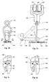
- an evisceration means and a fixing means are combined to form an evisceration and fixing means 1.
- the evisceration means is known per se from NL-A-8400506, and comprises an elongated carrier 2, at one end of which a scoop 6 is fixed so that it pivots about a shaft 4.
- An evisceration operating rod 8 is pivotally fixed to the scoop 6 by means of a shaft 10, in such a way that when the evisceration operating rod 8 is moved in the direction of arrow 12 the scoop 6 swings in the direction of the arrow 13 - from the position shown by a solid line in Fig. 1a to the position shown by a dashed line in the same figure.
- the scoop 6 is provided with a longitudinal slit 14, which widens towards the centre of the scoop 6.
- a fixing means is added to the conventional evisceration scoop.
- Said fixing means comprises a first clamping part 16 which is fixed at the abovementioned end of the elongated carrier 2, and a second clamping part 20 which is hingedly connected thereto by means of a shaft 18.
- the second clamping part 20 is provided with an arm 22 which is hingedly connected by means of a shaft 24 to a fixing operating rod 26. Moving the fixing operating rod 26 in the direction of the arrow 28 causes the second clamping part 20 to swing in the direction of the arrow 30, with the result that a clamping slit 32 between the first clamping part 16 and the second clamping part 20 widens.
- a shoulder 34 provided at the end of the fixing operating rod 26 facing away from the scoop 6 and a compression spring 36 interacting therewith ensure that the second clamping part 20 always returns to the position shown in Fig. lb when no force is exerted on the fixing operating rod 26 in the direction of arrow 28.
- the spring 36 determines the force which is necessary for enlargement of the clamping slit 32, or - in other words - determines the force with which the second clamping part 20 is pushed towards the first clamping part 16 at the position of the clamping slit 32.
- Figs. 1a, 1b, 4a and 4b illustrate, the evisceration and fixing means 1 shown in Figs. 1a and 1b is moved in the position shown by solid lines in the last-mentioned figures into the body of a slaughtered animal, for example a slaughtered bird 80 hanging by the legs from a hook 81, through an evisceration opening in the body in the region of the vent.
- the scoop 6 will have to be capable of reaching past the major part of the organ cluster to the vicinity of the neck of the slaughtered animal, as illustrated in Fig. 4b.
- the neck region may be reached along the back side of the carcass, as shown in the figures, or along the front side thereof.
- the gullet 38a present in the clamping slit 32 is consequently fixed relative to the two clamping parts 16 and 20. This is illustrated in Fig. 4c.
- the next step is to move the evisceration and fixing means 1 out of the slaughtered animal in the lengthwise direction of the carrier 2, with the result that the gullet breaks off at the side of the clamping slit 32 facing away from the carrier 2 and the scoop 6 removes the cluster of organs 38 situated at the level of the carrier 2 from the body of the slaughtered animal.
- the fixing of the gullet in the clamping slit 32 is retained during this process.
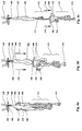
- Figs. 2a - 2d show views of a stripping means which is suitable for moving both along a straight (vertical) line and along a curved, for example circular, path.
- the stripping means comprises a top supporting plate 40 and a bottom supporting plate 42, between which a number of pairs of essentially vertically directed, mutually parallel guide rods 44 are fixed by means of bolts 46.
- a bearing block 48 can slide along the guide rods 44 through being provided with holes and bearings on the guide rods 44.
- the bearing block 48 is provided with a laterally projecting cam 50, on which a guide wheel 52 is mounted in such a way that it rotates about an axis 54.
- Said guide wheel 52 is guided in a curved track 56 in a control part 58, in such a way that on displacement of the combination of the top supporting plate 40, the bottom supporting plate 42 and the guide rods 44 the bearing block 48 carries out a desired movement along the guide rods 44.
- two elongated stripping elements 60 and 62 are provided on the bearing block 48 in such a way that at one end thereof they pivot about bushes 64 and 66 respectively.
- the stripping elements 60 and 62 are a special curved shape and can assume either a position relative to each other in which they partially overlap - a so-called closed position shown in Fig. 2c - or a position in which a certain space exists between the two elements - a so-called open position shown in Fig. 2d.
- the bushes 64 and 66 of the stripping elements 60 and 62 are each mechanically connected to a control element 68, which can be moved relative to the bearing block 48 in a plane at right angles to the bushes 64 and 66.
- the control element 68 is forced against the action of a compression spring 70 out of the position shown in Fig. 2c by a force in the direction of the bearing block 48, the bushes 64 and 66 pivot through a small angle in opposite directions to each other, with the result that the stripping elements go into the open position shown in Fig. 2d.
- the stripping elements assume the closed position again through the action of the compression spring 70.
- a stripping aperture 72 is determined through the shape of said elements.
- Said aperture 72 can be set by means of set screws 73, the head of which serves as a stop for the stripping elements 60 and 62.
- the stripping elements in their closed position in which they enclose a part of a cluster of organs in the stripping aperture 72, can sweep along the cluster of organs if the cluster of organs is set up in a fixed position relative to the guide rods 44 and the stripping elements 60, 62 are moved along the guide rods 44 by means of the earlier discussed curved track control.
- the stripping means shown in Figs. 3a - 3c differs from the stripping means shown in Figs. 2a - 2d only in the shape and the control of the stripping elements.
- the description of the stripping means according to Figs. 3a - 3c will therefore be limited here to the stripping elements and the way in which they are operated.
- Two pins 90 and 92 are fixed on the bearing block 48 which is slidable along the guide rods 44, near the lower corner points thereof, on which pins bushes 94 and 96 respectively are rotatably mounted.
- An arm 98 and a control lever 100 are immovably connected to bush 94.
- An arm 102 and a control lever 104 are rigidly connected to the bush 96.
- a stripping element 106 is fixed at the end of the arm 98 facing away from the bush 94, while a stripping element 108 is fixed at the end of the arm 102 facing away from the bush 96.
- the arms 98 and 102 are interconnected by means of a pre-tensioned tension spring 110.
- the control lever 100 is rigidly connected to an elongated control pin 112, which extends into a curved track 114 of the control part 58.
- the bearing block 48 is provided with a slit 116, by means of which the control pin 112 can move up and down while following the curved track 114.
- the control lever 100 rigidly connected to the control pin 112 will ensure that the stripping element 106 moves essentially in the plane thereof.
- the control lever 104 is provided at the end thereof facing away from the bush 96 with an elongated slit 118, which serves to accommodate the control pin 112.
- a movement of the control pin 112 in the slit 116 thus produces a movement of both the control lever 100 and the control lever 104, with the result that the stripping elements 106 and 108 will move away from or towards each other and thereby assume an open or closed position.
- Fig. 3c shows the closed position of the stripping elements 106 and 108, a passage 120 determined by recesses in the stripping elements 106 and 108 being clearly visible.
- Figs. 4h and 4i illustrate a stripping operation, in which, by way of example, the stripping elements 60 and 62 are shown only diagrammatically.
- the plate-shaped stripping elements 106 and 108 can also be used.
- the cluster of organs 38 is fixed at the gullet 38a thereof by clamping between two clamping elements 74 and 76.
- Fig. 4h shows, the stripping elements 60 and 62 are taken into the closed position first of all.
- the stripping elements are then (see Fig. 4i) moved jointly down in a direction away from the clamping elements 74 and 76, the clamping elements not being moved. Consequently, a force is exerted on organs in the cluster 38, by which force tissue connections are broken.
- the organs 77 such as the lungs, the heart or the like, stripped away from the cluster of organs as a result of this stripping operation, are collected on conveyor belts 78 and discharged for further processing.
- a mechanical transfer operation between the first-mentioned and last-mentioned operations is necessary.
- This transfer operation is illustrated in Figs. 4e - 4g.
- the cluster of organs 38 is conveyed away from the slaughtered animal 80. It can be seen clearly in Fig. 4e that a part of the gullet 38a is situated at a predetermined position under the clamping slit 32, where it is clamped between the clamping parts 16 and 20.
- This fixing means comprises an essentially U-shaped bracket 130, which is provided with an integral suspension eye 132.
- the bracket 130 is fixed by the eye 132 by means of a screw in a forked end 134 of an essentially Y-shaped conveyor element 136, two legs of which are provided with runners 138.
- the runners 138 make a movement of the fixing means along the laterally projecting flanges of an inverted T-shaped rail 140 possible, for example by means of a chain (not shown).
- the free ends of the bracket 130 are fixed in essentially plate-shaped clamping elements 144 and 146 which are interconnected and are pivoted about a shaft 142.
- the clamping element 144 bears a clamping part 148, which at the side facing the clamping element 146 is provided with a longitudinal groove whose width is approximately the same as the thickness of the clamping element 146.
- the fixing means can be moved from a closed position, shown in Fig. 5c, to an open position, shown in Fig. 5d, by pushing the legs of the bracket 130 apart, as will be described with reference to FigS. 5a and 5b.
- a control lever 150 disposed along the rail 140 and movable along with the fixing means at least over a certain distance can pivot about a shaft 152, as indicated by means of the double arrow 154.
- the end of the control lever 150 is provided with a wearproof and friction-reducing covering 156 and has a width which is greater than the distance between the legs of the bracket 130 in the vicinity of the clamping elements 144 and 146 in the closed position of the fixing means.
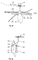
- Fig. 6a shows how a cluster of organs 38 from a bird is fixed at the gullet 160 thereof relative to the fixing means which is described with reference to Figs. 5a - 5d, and only a part of which is shown.
- the cluster of organs comprises lungs 162, glandular stomach 164, gizzard 166, heart 168, liver 170, intestines 172 and cloaca 174.
- Fig. 6b shows the result of a stripping operation carried out with the stripping means described before with reference to Figs. 3a - 3c. Only the stripping elements 106 and 108 of this stripping means are shown in Fig. 6b. Starting from the situation shown in Fig.
- Fig. 6c shows the situation which arises when the stripping elements 106 and 108 are moved even further away from the fixing point of the cluster of organs (in this case the gullet 160).
- the useful organs such as heart, liver 170 and lungs 162, come under the stripping elements 106 and 108 here, hanging at a certain point from the cluster of intestines 172.
- the part of the intestines adjoining the gizzard 166, comprising the duodenum 173 plays an important role here. From the position shown in Fig. 6c, it is particularly simple to feed heart, liver and lungs automatically with the aid of the fixing means and suitable guides to a device known per se for separating said organs.
- the cluster of organs 161 shown diagrammatically in Figs. 6d and 6e is fixed at the gullet 160 in the fixing means already shown in Figs. 5a - 5d, and is moved along in the direction of the arrow 200. Going from right to left in Fig. 6d, the cluster of organs 161 first meets an inlet side 177a of a guide plate 177 which extends essentially parallel to the direction of conveyance 200, and is disposed in a manner not shown in any further detail in a frame.
- the arrangement of the guide plate 177 at an angle with the vertical ensures that the cluster of organs 161 is oriented in such a way that an organ 179 to be separated finishes up at the side of the cluster of organs 161 facing away from the guide plate 177 between guide rods 181a and 181b, the major part of which extends parallel to the guide plate 177 and in the direction of conveyance 200.
- the guide rods 181a and 181b disposed in a manner not shown in any further detail in the abovementioned frame, define between them a guide slit which in an inlet part converges in the direction of conveyance 200.
- the organ 179 thus finishes up at one side of the guide slit, while the remaining organs finish up at the other side of the guide slit.
- the width of the guide slit is selected so that it is small enough to prevent the organ 179 from passing through the slit in the direction of the guide plate 177.
- the distance of the guide rods 181a and 181b from the guide plate 177 is so small that the cluster of organs 161 is compressed locally. This helps to make the organ 179 bulge out from the cluster of organs and promotes correct positioning of the organ relative to the guide slit.
- a rotary cutter 185 driven by a motor 183 is set up, by means of which the connection between the organ 179 and the remainder of the cluster of organs 161 is broken automatically during conveyance in the direction of the arrow 200.
- the organ 179 for example a heart from a cluster of organs of a bird, is then discharged for further processing. Yet other organs can be separated from the cluster of organs 161 in a similar way.
- Figs. 6f and 6g show a cluster of organs 161 fixed at the gullet 160 in the fixing means according to Fig. 5a - 5d, and moving in the direction of arrow 200.
- three guide rods 181c, 181d, and 181g extend essentially parallel to the direction of conveyance 200.
- Two parallel stripping plates 181e and 181f extend below the guide rods 181c and 181d.
- the guide rods 181c, 181d, 181g, and the stripping plates 181e, 181f are disposed in a manner not shown in any further detail in a frame and are each provided with suitable feed-in parts.
- the guide rods 181c and 181d cross, when seen from the fixing means.
- the stripping plates 181e and 181f diverge from the guide rods 181c, 181d, defining a guide slit between them.
- the cluster of organs 161 is caught between the guide rods 181c, 181d, and 181g, which are disposed such that a predetermined organ 179a or organs is/are brought at a distance from the other organs of the cluster 161, and the tissue connection between the organ(s) 179a and the rest of the cluster is caught between the guide rods 181d and 181g.
- the other organs are caught in and under the guide slit between the stripping plates 181e, 181f.
- the stripping plates may be made from rigid or flexible, resilient material.
- the width of the guide slit between the stripping plates may be varied along its length to provide a suitable passage for certain organs in the cluster.
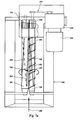
- Figs. 7a and 7b illustrate the design and mode of operation of separating means, which are used for separating intestines, and possibly gall-bladder from a cluster of organs of a bird, which cluster of organs is clamped e.g. at the position of the gullet 160 by means of clamping elements 144 and 146.
- the separating means comprise a container 180 which is provided with an outlet, and above which two elongated, parallel rollers 182, 184 which are rotatable in opposite directions relative to each other are mounted.
- the rollers are driven by a motor 186 by way of a reducer 188 and a belt transmission 190, the belt of the belt transmission 190 being coupled directly to a drive wheel of the roller 184, which roller is provided at one end thereof with a gear wheel 192 which meshes with a gear wheel 194 of the roller 182.
- the rollers 182 and 184 will thus rotate in opposite directions when driven, as indicated by the arrows 196 and 197.
- the roller 184 is provided with a helical conveyor rib 198 on the outside surface thereof, with a pitch which is considerably smaller than the length of the roller 184.
- the conveyor rib 198 brings about conveyance of the organs present between the rollers 182 and 184, in the direction indicated by the arrow 200 in the case of the directions of rotation 196 and 197 of the rollers 182, 184.
- the roller 184 is also provided on its external surface with three helical separating ribs 202, the pitch of which is considerably greater than the length of the roller 184.
- the roller 182 is provided on its external surface with three grooves 204, which are shaped in a complementary way to the ribs 202 of the roller 184, and at least partially accommodate said ribs 202 when a part of a rib 202 is lying in the nip of the rollers 182 and 184.
- the combination of the ribs 202 and the grooves 204 causes a downward directed force upon the organs, such as intestines, lying between the rollers.
- separating means in Fig. 7a are shown only in a very rough diagram in Fig. 7b.
- Above the separating means shown in the central part of the figure is a conveyor, along which fixing means such as those shown in Fig. 5a are moved in the direction of the arrow 200.
- the clusters of organs 210 of a bird conveyed by the fixing means are guided by one or more diagrammatically shown guide rods 212 between the rollers 182 and 184, only the latter of which is shown in Fig. 7b.
- the downward force exerted by the rollers 182 and 184 on the intestines means that the intestines are pulled completely below the rollers, in which case the action of the ribs 202 and grooves 204 causes the connection between the gizzard 166 and the cluster of intestines 172 to be broken.
- the cluster of internal organs 210' is then conveyed further along the conveyor, hanging from the fixing means, while the intestines fall from the separating means into the container 180 and are discharged from there.
- organ blocking means in the form of two vertical strips 201, disposed on either side of the nip of the rollers 182 and 184, is shown by dashed lines in Fig. 7b.
- the distance between the strips 201 is selected in such a way that the intestines 172 can move through between the strips 201, and can also take the gall-bladder 203 along with them until it is between the strips 201.
- a cutter 205 extending between the strips 201, the sharp edge of which faces in the opposite direction to that of the arrow 200, separates the intestines 172 and gall-bladder 203, on the one hand, from the remaining organs, on the other.
- Fig. 7c and 7d shows in a rough diagram similar to Fig. 7b the processing steps and devices used for separating intestines and gall-bladder from a cluster of organs 210, fixed by fixing means such as those shown in Fig. 5a, and moving in the direction of arrow 200. It is remarked that all structural elements of devices are connected to and supported by a frame (not shown for the sake of clarity).
- the cluster of organs 210 is first fed to one or more stretching rollers 250, which are rotated in the direction of arrow 252 and are provided on its outer surface with radially and axially extending flaps made of a resilient material, such as a rubber compound.
- the flaps 254 stroke the cluster of organs 210 at the height where the bundle of intestines 172 is situated, thereby breaking tissue connections between parts of the intestines and unfolding the bundle to an extent which is illustrated in Fig. 7c.
- the separating device 256 contains a guide slit 258 into which the intestines 172, stretched by one or more stretching rollers 250, are fed by conveying the fixing means in the direction of the arrow 200.
- the cluster of organs above the guide slit 258 is led to one side thereof by guide rod 260.
- the cluster 210 When brought to this side, the cluster 210 is guided by a guide plate 262 and held away from the guide slit 258, while the intestines 172 are caught in the guide slit 258 and between rollers 182, 184, of which only the latter is visible. When conveyed along, the cluster is pulled over sloping part 264 which orientates the cluster such that the liver is brought down.
- the part of the separating means 256 to which the cluster is next conveyed contains two walls 266, 268 extending upwards from the edges of the guide slit 258 facing each other.
- the wall 266 is part of a guide structure 270 containing a duct 272 for providing a water knife across the upper part of the guide slit defined by walls 266, 268.
- a water jet from duct 272 is directed into an opening of a vacuum tube 274 connected to wall 268.
- the vacuum tube 274 also has an aperture of which the dimensions are such that the gall-bladder 203 can pass therethrough.
- a guide slit blocking element 276 is provided in the guide slit 258 adjacent to the vacuum tube 274.
- the water jet from duct 272 cuts off the gall-bladder 203 and any remaining parts of the intestines 172 from the cluster 210, and the gall-bladder 203 and intestine parts are removed through the vacuum tube 274.
- a stationary or moving knife can be used for the same purpose.
- a rotary cylindrical hollow knife may be provided, the end of which pointing opposite to the direction of conveyance 200 having an axial knife edge and an inner diameter which is sufficiently large to let a gall-bladder pass.
- the interior of the rotating cylindrical knife is part of a vacuum system. In this way, the gall-bladder is drawn into the hollow knife at the knife edge end thereof by the partial pressure in the knife, and then the gall-bladder is separated from the cluster by a cutting operation of the knife edge of the hollow rotary knife.
- Fig. 8 shows how a slaughtered animal 222 is fed on a conveyor 220a to an evisceration device 224 of a carrousel type known per se.
- the eviscerated carcass is then discharged on conveyor 220b by way of an inspection station 226 with a veterinary inspector 227, who may if desired be replaced by a computer vision inspection system.
- a veterinary inspector 227 who may if desired be replaced by a computer vision inspection system.
- the evisceration device 224 which is equipped with evisceration means of the type shown in Figs.
- the cluster of organs which has been removed is transferred to a conveyor 228a with fixing means of the type shown in Figs. 5a - 5d.
- the conveyors 220b and 228a run parallel and in synchronism along of the inspection station 226, it being ensured that a cluster of organs passes the inspection station 226 at the same time as the carcass to which it belongs, so that the relation between the cluster of organs and the carcass is directly apparent. However, if this relation is established in a different way, carcasses can also be inspected separately from their clusters of organs, as illustrated by dashed lines in the figure with conveyor part 220c and inspection station 228.
- the heart can be removed from the cluster of organs in a processing station 230 (for example, in the manner shown in Figs. 6d and 6e), and the intestines and the gall-bladder can be removed from the cluster of organs in a processing station 232 (for example, in the manner shown in Fig. 7b).
- a processing station 230 for example, in the manner shown in Figs. 6d and 6e
- the intestines and the gall-bladder can be removed from the cluster of organs in a processing station 232 (for example, in the manner shown in Fig. 7b).
- the sequence of the processing stations 230 and 232 along the conveyor belt 228a can also be reversed, while they can also be left out entirely in the organ separating line shown in Fig. 8.
- the cluster of remaining organs is then fed to a stripping device 234, for example of the type shown in Figs. 2a - 2d or 3a - 3c. If the cluster of organs has already undergone a processing operation in processing station 232, the stripping operation in stripping device 234 will result in at least the organs liver, heart and lungs being separated completely from the remainder of the cluster of organs. Said organs can then be processed further, possibly partially by hand, along a conveyor belt 236. It will be clear that the heart will not be present on the conveyor belt 236 if the cluster has already undergone an operation in processing station 230.
- the stripping operation in stripping device 234 will generally be carried out only until the processing stage shown in Fig. 6b or Fig. 6c has been reached.
- the cluster of organs can be supplied in this state by way of a conveyor 220d to a device 238 which is known per se for separating liver, heart and lungs. Finally, the stomachs remaining from the cluster of organs are separated and processed in a stomach machine 240.
Priority Applications (6)
| Application Number | Priority Date | Filing Date | Title |
|---|---|---|---|
| EP98203531A EP0890315B2 (de) | 1992-09-10 | 1993-09-10 | Verfahren und Vorrichtung zur Bearbeitung eines Organ-Pakets eines Schlachttieres |
| EP06077213A EP1769681B1 (de) | 1992-09-10 | 1993-09-10 | Verfahren und Vorrichtung zur Bearbeitung des Organpakets eines Schlachttieres |
| ES06077213T ES2306360T3 (es) | 1992-09-10 | 1993-09-10 | Metodo y dispositivo para procesar un grupo de organos de un animal sacrificado. |
| EP01202685A EP1135990B1 (de) | 1992-09-10 | 1993-09-10 | Verfahren und Vorrichtung zur Bearbeitung des Organpakets eines Schlachttieres |
| EP96203580A EP0769247B1 (de) | 1992-09-10 | 1993-09-10 | Verfahren und Vorrichtung zur Bearbeitung eines Organ-Pakets eines Schlachttieres |
| EP98200479A EP0852908B2 (de) | 1992-09-10 | 1993-09-10 | Verfahren und Vorrichtung zur Bearbeitung eines Organen-Pakets eines Schlachttieres |
Applications Claiming Priority (4)
| Application Number | Priority Date | Filing Date | Title |
|---|---|---|---|
| NL9201574 | 1992-09-10 | ||
| NL9201574A NL9201574A (nl) | 1992-09-10 | 1992-09-10 | Werkwijze en inrichting voor het verwijderen en verwerken van een organenpakket van een slachtdier. |
| NL9300815 | 1993-05-12 | ||
| NL9300815A NL9300815A (nl) | 1992-09-10 | 1993-05-12 | Werkwijze en inrichting voor het verwijderen en verwerken van een organenpakket van een slachtdier. |
Related Child Applications (2)
| Application Number | Title | Priority Date | Filing Date |
|---|---|---|---|
| EP96203580A Division EP0769247B1 (de) | 1992-09-10 | 1993-09-10 | Verfahren und Vorrichtung zur Bearbeitung eines Organ-Pakets eines Schlachttieres |
| EP96203580.4 Division-Into | 1996-12-18 |
Publications (3)
| Publication Number | Publication Date |
|---|---|
| EP0587253A2 true EP0587253A2 (de) | 1994-03-16 |
| EP0587253A3 EP0587253A3 (de) | 1994-08-31 |
| EP0587253B1 EP0587253B1 (de) | 1997-04-16 |
Family
ID=26647012
Family Applications (6)
| Application Number | Title | Priority Date | Filing Date |
|---|---|---|---|
| EP01202685A Expired - Lifetime EP1135990B1 (de) | 1992-09-10 | 1993-09-10 | Verfahren und Vorrichtung zur Bearbeitung des Organpakets eines Schlachttieres |
| EP93202639A Expired - Lifetime EP0587253B1 (de) | 1992-09-10 | 1993-09-10 | Verfahren und Vorrichtung zur Bearbeitung eines Organen-Pakets eines Schlachttieres |
| EP98203531A Expired - Lifetime EP0890315B2 (de) | 1992-09-10 | 1993-09-10 | Verfahren und Vorrichtung zur Bearbeitung eines Organ-Pakets eines Schlachttieres |
| EP06077213A Expired - Lifetime EP1769681B1 (de) | 1992-09-10 | 1993-09-10 | Verfahren und Vorrichtung zur Bearbeitung des Organpakets eines Schlachttieres |
| EP96203580A Revoked EP0769247B1 (de) | 1992-09-10 | 1993-09-10 | Verfahren und Vorrichtung zur Bearbeitung eines Organ-Pakets eines Schlachttieres |
| EP98200479A Expired - Lifetime EP0852908B2 (de) | 1992-09-10 | 1993-09-10 | Verfahren und Vorrichtung zur Bearbeitung eines Organen-Pakets eines Schlachttieres |
Family Applications Before (1)
| Application Number | Title | Priority Date | Filing Date |
|---|---|---|---|
| EP01202685A Expired - Lifetime EP1135990B1 (de) | 1992-09-10 | 1993-09-10 | Verfahren und Vorrichtung zur Bearbeitung des Organpakets eines Schlachttieres |
Family Applications After (4)
| Application Number | Title | Priority Date | Filing Date |
|---|---|---|---|
| EP98203531A Expired - Lifetime EP0890315B2 (de) | 1992-09-10 | 1993-09-10 | Verfahren und Vorrichtung zur Bearbeitung eines Organ-Pakets eines Schlachttieres |
| EP06077213A Expired - Lifetime EP1769681B1 (de) | 1992-09-10 | 1993-09-10 | Verfahren und Vorrichtung zur Bearbeitung des Organpakets eines Schlachttieres |
| EP96203580A Revoked EP0769247B1 (de) | 1992-09-10 | 1993-09-10 | Verfahren und Vorrichtung zur Bearbeitung eines Organ-Pakets eines Schlachttieres |
| EP98200479A Expired - Lifetime EP0852908B2 (de) | 1992-09-10 | 1993-09-10 | Verfahren und Vorrichtung zur Bearbeitung eines Organen-Pakets eines Schlachttieres |
Country Status (7)
| Country | Link |
|---|---|
| US (1) | US5549521A (de) |
| EP (6) | EP1135990B1 (de) |
| JP (1) | JPH06189670A (de) |
| DE (6) | DE69334215T2 (de) |
| DK (6) | DK0769247T3 (de) |
| ES (6) | ES2306360T3 (de) |
| NL (1) | NL9300815A (de) |
Cited By (20)
| Publication number | Priority date | Publication date | Assignee | Title |
|---|---|---|---|---|
| WO1995019710A1 (en) * | 1994-01-19 | 1995-07-27 | Matforsk, Norwegian Food Research Institute | Devices for removing sinew |
| EP0679336A1 (de) * | 1994-04-26 | 1995-11-02 | Machinefabriek Meyn B.V. | Verfahren und Vorrichtung zum Trennen von aus einem Schlachtgeflügel entfernten Eingeweiden |
| NL1000798C2 (nl) * | 1995-07-14 | 1997-01-15 | Meyn Maschf | Inrichting voor het in losse onderdelen verdelen van een samenstel uit hart en longen. |
| US5707280A (en) * | 1996-01-19 | 1998-01-13 | Johnson Food Equipment Inc. | Crop inclusive poultry eviscerating method and apparatus |
| EP0839455A1 (de) | 1996-10-30 | 1998-05-06 | Systemate Holland B.V. | Ausnehmer |
| US5810651A (en) * | 1996-05-14 | 1998-09-22 | Machinefabriek Meyn B.V. | Apparatus for processing an entrails package removed from slaughtered poultry |
| NL1006580C2 (nl) * | 1997-07-14 | 1999-01-15 | Stork Pmt | Werkwijze en inrichting voor het verwerken van geslacht gevogelte, alsmede transportorgaan voor toepassing in een dergelijke werkwijze en inrichting. |
| WO2000033661A1 (en) * | 1998-12-07 | 2000-06-15 | Lindholst & Co. A/S | Method and apparatus for separating intestine packs from slaughtered poultry, particularly broilers |
| NL1015682C2 (nl) | 2000-01-18 | 2001-07-19 | Stork Pmt | Uithaalorgaan, inrichting en werkwijze voor het verwerken van een ingewandenpakket van een slachtdier. |
| KR100323482B1 (ko) * | 1999-09-03 | 2002-03-13 | 김선유 | 도체 내장 자동 분리 장치 |
| EP1188381A1 (de) * | 2000-09-15 | 2002-03-20 | Slagteriernes Forskningsinstitut | Apparat und Verfahren zum Trennen eines Organs aus einer Gruppe von Organen einer Karkasse |
| EP1222858A2 (de) * | 2001-01-12 | 2002-07-17 | Stork Pmt B.V. | Verfahren und Vorrichtung zur Bearbeitung des Organ-Pakets eines Schlachttieres |
| EP2803273A1 (de) * | 2013-05-14 | 2014-11-19 | Linco Food Systems A/S | Verfahren, System und Führungsanordnung zum Trennen von Innereiensätzen, die aus geschlachtetem Geflügel entnommen wurden |
| WO2016013931A1 (en) * | 2014-07-24 | 2016-01-28 | Marel Stork Poultry Processing B.V. | Method and device for evisceration of slaughtered poultry |
| US9648887B2 (en) | 2013-11-14 | 2017-05-16 | Linco Food Systems A/S | Guide member, a guide system and a method for separating a viscary set eviscerated from slaughtered poultry |
| EP2110021B2 (de) † | 2007-02-06 | 2017-12-27 | Mayekawa Mfg. Co., Ltd. | Verfahren und vorrichtung zur entbeinung eines picknick- oder oberschenkelteils |
| WO2018088903A1 (en) * | 2016-11-10 | 2018-05-17 | Marel Stork Poultry Processing B.V. | Shackle for suspending viscera packs of slaughtered poultry in a processing line |
| WO2018093249A2 (en) | 2016-11-15 | 2018-05-24 | Marel Stork Poultry Processing B.V. | Method and system for the processing of clusters of poultry viscera |
| NL2018174B1 (en) * | 2017-01-16 | 2018-07-26 | Meyn Food Processing Tech Bv | Evisceration apparatus and a method for eviscerating sus-pended poultry |
| CN113331242A (zh) * | 2021-05-19 | 2021-09-03 | 曹海平 | 一种整体翻转式双面检测猪肉淋巴去除装置 |
Families Citing this family (47)
| Publication number | Priority date | Publication date | Assignee | Title |
|---|---|---|---|---|
| US6186881B1 (en) | 1996-09-20 | 2001-02-13 | Foodcraft Equipment Co., Ltd. | Method and apparatus for venting/opening, eviscerating/cropping, inspecting and cleaning of poultry |
| US5993308A (en) | 1996-09-20 | 1999-11-30 | Foodcraft Equipment Company | Machine for eviscerating and displaying poultry for inspection |
| DE60120956T2 (de) * | 2000-04-11 | 2007-02-08 | Linco Food Systems A/S | Verfahren und vorrichtung zur inspektion von schlachtgeflügel, insbesondere brathähnchen |
| US6905404B2 (en) | 2002-01-24 | 2005-06-14 | Maple Leaf Foods, Inc. | System for harvesting animal parts |
| DK175570B1 (da) * | 2002-06-26 | 2004-12-13 | Slagteriernes Forskningsinst | Apparat og fremgangsmåde til automatisk afskæring af hjerte og lunger fra et pluckssæt fra en slagtekrop |
| DK200301518A (da) | 2003-10-15 | 2005-04-16 | Linco Food Systems As | Indvoldsudtagning |
| US7252583B1 (en) | 2006-04-28 | 2007-08-07 | Jones Ronald T | Easy big game field dressing apparatus |
| CN101679950A (zh) * | 2007-02-22 | 2010-03-24 | 国立大学法人东京大学 | 利用胚泡互补的器官再生法 |
| US7500910B2 (en) * | 2007-08-06 | 2009-03-10 | Johnson Food Equipment, Inc. | Device and method for clamping and cutting |
| DK2294922T3 (en) | 2008-03-20 | 2017-10-09 | Meyn Food Processing Tech Bv | Device for skinning crows |
| NL2002836C2 (en) * | 2009-05-04 | 2010-11-08 | Meijn Food Proc Technology B V | Gizzard peeler and method of peeling a gizzard. |
| US8632380B2 (en) | 2010-01-26 | 2014-01-21 | Foodmate B.V. | Method and apparatus for removing a sleeve of meat from an animal part having bone with knuckles on each of its opposite ends |
| US8157625B2 (en) | 2010-01-26 | 2012-04-17 | Foodmate Bv | Method and apparatus for collecting meat from an animal part |
| US8789684B2 (en) | 2010-04-19 | 2014-07-29 | Foodmate Bv | Rotatable article support for a conveyor |
| NL2004574C2 (en) | 2010-04-19 | 2011-10-20 | Foodmate B V | Rotatable article support for a conveyor. |
| NL2006075C2 (en) | 2011-01-26 | 2012-07-30 | Foodmate B V | Rotationally indexed article support for a conveyor system having an alignment station. |
| NL2004573C2 (en) | 2010-04-19 | 2011-10-20 | Foodmate B V | Turning block alignment. |
| US8757354B2 (en) | 2010-04-19 | 2014-06-24 | Foodmate Bv | Turning block alignment |
| US8549996B2 (en) | 2010-05-28 | 2013-10-08 | Dole Fresh Vegetables, Inc. | System for topping and tailing lettuce heads using a camera-guided servo-controlled water knife |
| US8727839B2 (en) | 2011-01-21 | 2014-05-20 | Foodmate Bv | Poultry wing cutter for narrow pitch poultry lines |
| US8267241B2 (en) | 2011-01-26 | 2012-09-18 | Foodmate Bv | Rotationally indexed article support for a conveyor system having an alignment station |
| US8882571B2 (en) | 2011-01-26 | 2014-11-11 | Foodmate Bv | Method of deboning animal thighs for separating and collecting meat therefrom and apparatus for performing the method |
| DK2667728T3 (en) | 2011-01-26 | 2015-10-19 | Foodmate Bv | Process for bone dyrelår of separation and collection of meat thence and device for performing the method |
| US8430728B2 (en) | 2011-02-14 | 2013-04-30 | Foodmate Bv | Special cut poultry wing cutter |
| NL2009033C2 (en) | 2012-06-19 | 2013-12-23 | Foodmate B V | Weighing method and apparatus. |
| BR112014032052B1 (pt) * | 2012-07-04 | 2019-10-22 | Marel Meat Processing Bv | sistema para transportar carcaças ou partes de carcaças de animais quadrúpedes para abate |
| NL2009718C2 (en) | 2012-10-29 | 2014-05-01 | Foodmate B V | Method of mechanically removing skin from animal parts. |
| US8808068B2 (en) | 2012-10-29 | 2014-08-19 | Foodmate Bv | Method of and system for automatically removing meat from an animal extremity |
| WO2014125118A1 (en) * | 2013-02-18 | 2014-08-21 | Dat-Schaub A/S | Apparatus and process for cutting off small intestines |
| KR101465315B1 (ko) * | 2013-02-20 | 2014-12-04 | 주식회사 태진 | 도계용 간분리기 |
| US9078453B2 (en) | 2013-11-01 | 2015-07-14 | Foodmate B.V. | Method and system for automatically deboning poultry breast caps containing meat and a skeletal structure to obtain breast fillets therefrom |
| NL2011818C2 (en) * | 2013-11-19 | 2015-05-26 | Meyn Food Proc Technology Bv | Apparatus and method for removing the entrails from the abdominal cavity of poultry. |
| US8961274B1 (en) | 2013-12-18 | 2015-02-24 | Foodmate Bv | Selective tendon cutter and method |
| NL2012464B1 (en) * | 2014-03-18 | 2015-12-15 | Meyn Food Proc Technology Bv | Method, processing device and processing line for mechanically processing an organ or organs taken out from slaughtered poultry. |
| NL2012465B1 (en) | 2014-03-18 | 2015-12-15 | Meyn Food Proc Technology Bv | Method, processing device and processing line for mechanically processing an organ or organs taken out from slaughtered poultry. |
| NL2012466B1 (en) | 2014-03-18 | 2015-12-15 | Meyn Food Proc Technology Bv | Method, processing device and processing line for mechanically processing an organ or organs taken out from slaughtered poultry. |
| CN104170939B (zh) * | 2014-07-18 | 2016-03-16 | 湖南农业大学 | 一种肠须去除机 |
| US9485996B2 (en) | 2014-12-31 | 2016-11-08 | Robert E. Ellis | Game dressing tool |
| NL2014512B1 (en) | 2015-03-24 | 2017-01-19 | Meyn Food Proc Technology Bv | Apparatus for mechanically processing an organ or organs taken out from slaughtered poultry. |
| CN105475453B (zh) * | 2015-11-30 | 2018-01-23 | 吉林省艾斯克机电股份有限公司 | 一种自动去除家禽颈皮的装置及方法 |
| CN105379819B (zh) * | 2015-12-08 | 2018-10-23 | 中国包装和食品机械有限公司 | 一种夹取式家禽自动取内脏机械手 |
| DK3372087T3 (da) | 2017-03-09 | 2020-02-03 | Linco Food Systems As | Renseværktøj og renseindretning med et sådant renseværktøj |
| CN110115458B (zh) * | 2018-02-06 | 2021-05-14 | 河南科技大学第一附属医院 | 一种病理学教学用器官展示台 |
| NL2021483B1 (en) * | 2018-08-20 | 2020-02-26 | Meyn Food Processing Tech Bv | Intestines processing system and method for processing an intestines package |
| CN110313509B (zh) * | 2019-07-11 | 2021-03-23 | 南京深农智能装备有限公司 | 一种家禽食管加工设备 |
| CN110710560A (zh) * | 2019-10-29 | 2020-01-21 | 山东凤祥股份有限公司 | 一种鸡肠去除装置及方法 |
| NL2026986B1 (en) * | 2020-11-26 | 2022-07-04 | Meyn Food Processing Tech Bv | A processing line and method for harvesting hearts from vis-cera packages taken out and detached from poultry carcasses |
Citations (17)
| Publication number | Priority date | Publication date | Assignee | Title |
|---|---|---|---|---|
| GB1415153A (en) * | 1971-06-17 | 1975-11-26 | Stork Brabant Bv | Poultry processing machine gizzard cropper |
| US4019222A (en) * | 1976-01-30 | 1977-04-26 | Gordon Johnson Company | Poultry eviscerating method and apparatus |
| US4057875A (en) * | 1976-11-03 | 1977-11-15 | Hill Carl J | Feed apparatus for poultry gizzard processing machine |
| NL7705225A (nl) * | 1976-05-24 | 1977-11-28 | Wilson Foods Corp | Trekapparaat voor darmen, afkomstig van een varken of ander dier. |
| GB1507002A (en) * | 1975-02-19 | 1978-04-12 | Forsogsfjerkraeslagteriet | Method of drawing the gizzard and crop from slaughtered poultry |
| GB2004175A (en) * | 1977-09-14 | 1979-03-28 | Andersen B | An apparatus for separating the intestine and the gall bladder from the liver and the heart of slaughtered poultry |
| US4382313A (en) * | 1980-08-19 | 1983-05-10 | Centennial Machine Co., Inc. | Gizzard harvesting machine |
| US4467498A (en) * | 1983-11-21 | 1984-08-28 | Cantrell Machine Co., Inc. | Rotary viscera harvester |
| EP0141432A1 (de) * | 1981-03-04 | 1985-05-15 | Stork Pmt B.V. | Einrichtung zum Trennen des Magens vom übrigen Eingeweide bei geschlachtetem Geflügel |
| NL8400506A (nl) * | 1984-02-16 | 1985-09-16 | Stork Pmt | Inrichting voor het uithalen van de inwendige organen van geslacht gevogelte. |
| DE3709869A1 (de) * | 1987-03-26 | 1988-10-13 | Markert Maschf Bv | Ausnehmevorrichtung einer automatisch arbeitenden verarbeitungsanlage fuer gefluegeltiere |
| EP0439904A1 (de) * | 1990-02-02 | 1991-08-07 | Harben III, Grover S. | Verfahren und Vorrichtung zum Entnehmen von Herzen und Lebern von Geflügel |
| US5041052A (en) * | 1990-08-01 | 1991-08-20 | Cantrell Machine Company, Inc. | Liver harvesting system and method |
| EP0482700A1 (de) * | 1990-10-19 | 1992-04-29 | Stork Pmt B.V. | Verfahren und Vorrichtung zum Trennen des Herzens, der Lungen und der Leber von Geflügeleingeweide |
| EP0487168A1 (de) * | 1990-11-22 | 1992-05-27 | Stork Pmt B.V. | Vorrichtung zum selektiven Entfernen von Organen von Schlachttieren |
| NL9100153A (nl) * | 1991-01-30 | 1992-08-17 | Meyn Maschf | Inrichting voor het uithalen van slachtvogels. |
| EP0530868A1 (de) * | 1991-09-03 | 1993-03-10 | Machinefabriek Meyn B.V. | Verfahren und Vorrichtung zum Bearbeiten von Geflügel |
Family Cites Families (21)
| Publication number | Priority date | Publication date | Assignee | Title |
|---|---|---|---|---|
| GB356442A (en) * | 1930-08-19 | 1931-09-10 | Draw Trim Corp Of America | Improvements relating to the dressing of fowls |
| NL7100142A (de) * | 1971-01-07 | 1972-07-11 | ||
| NL168118C (nl) * | 1973-08-07 | 1982-03-16 | Stork Brabant Bv | Inrichtig voor het verwijderen van de ingewanden van geslacht gevogelte. |
| BE813138A (en) * | 1974-04-01 | 1974-07-31 | Automatic removal of intestines from chickens - as part of an automatic line for preparing 'oven ready' chickens | |
| NL158689C (nl) * | 1975-03-05 | 1980-12-15 | Meyn Pieter | Inrichting voor het verwijderen van de nek van een geplukte, van de kop ontdane vogel. |
| US4262387A (en) * | 1979-09-10 | 1981-04-21 | Simon-Johnson Inc. | Method and apparatus for eviscerating poultry |
| US4538325A (en) * | 1980-08-19 | 1985-09-03 | Centennial Machine Company, Inc. | Gizzard harvesting machine |
| US4570296A (en) * | 1982-05-04 | 1986-02-18 | Hill William J | Gizzard harvesting apparatus |
| NL8202031A (nl) * | 1982-05-17 | 1983-12-16 | Stork Pmt | Inrichting voor het verwijderen der ingewanden van geslacht gevogelte. |
| NL8300065A (nl) * | 1983-01-10 | 1984-08-01 | Systemate Bv | Inrichting voor het uithalen van slachtvogels. |
| JPS6119219A (ja) * | 1984-07-05 | 1986-01-28 | Fujitsu Ltd | アクテイブフイルタ |
| US4561148A (en) * | 1984-10-05 | 1985-12-31 | Simon-Johnson, Inc. | Machine for pulling viscera package from fowls |
| US4788749A (en) * | 1987-07-17 | 1988-12-06 | Hazenbroek Jacobus E | Crop removal system |
| NL8901551A (nl) * | 1989-06-20 | 1991-01-16 | Stork Pmt | Ontkropper voor gevogelte. |
| DE4101645A1 (de) | 1990-01-29 | 1991-08-01 | Gen Electric | Zweidimensionaler mosaikartiger szintillationsdetektor |
| US5098333A (en) * | 1990-03-29 | 1992-03-24 | Meyn Canada Poultry Inc. | Method and apparatus for removing viscera from poultry carcasses |
| NL189443C (nl) | 1990-04-03 | 1994-06-16 | Stork Pmt | Cloaca-snijder. |
| US5186679A (en) * | 1991-01-30 | 1993-02-16 | Machinefabriek Meyn B.V. | Apparatus for eviscerating slaughtered poultry |
| NL9101768A (nl) * | 1991-10-23 | 1993-05-17 | Meyn Maschf | Inrichting voor het verwijderen van de ingewanden uit de buikholte van gevogelte. |
| NL9101856A (nl) * | 1991-11-07 | 1993-06-01 | Meyn Maschf | Werkwijze en inrichting voor het in losse onderdelen scheiden van een uit een vogel verwijderd pakket bestaande uit darmen, lever en hart met longen. |
| NL9200599A (nl) * | 1992-03-31 | 1993-10-18 | Meyn Maschf | Inrichting voor het transporteren van uit vogels verwijderde ingewandenpakketten. |
-
1993
- 1993-05-12 NL NL9300815A patent/NL9300815A/nl not_active Application Discontinuation
- 1993-09-09 US US08/118,979 patent/US5549521A/en not_active Expired - Lifetime
- 1993-09-10 ES ES06077213T patent/ES2306360T3/es not_active Expired - Lifetime
- 1993-09-10 EP EP01202685A patent/EP1135990B1/de not_active Expired - Lifetime
- 1993-09-10 ES ES96203580T patent/ES2157398T3/es not_active Expired - Lifetime
- 1993-09-10 DE DE69334215T patent/DE69334215T2/de not_active Expired - Lifetime
- 1993-09-10 DK DK96203580T patent/DK0769247T3/da active
- 1993-09-10 DE DE69309816T patent/DE69309816T2/de not_active Expired - Lifetime
- 1993-09-10 EP EP93202639A patent/EP0587253B1/de not_active Expired - Lifetime
- 1993-09-10 JP JP5250031A patent/JPH06189670A/ja active Pending
- 1993-09-10 DE DE69327117T patent/DE69327117T2/de not_active Expired - Lifetime
- 1993-09-10 DE DE69330890T patent/DE69330890T3/de not_active Expired - Lifetime
- 1993-09-10 ES ES93202639T patent/ES2101216T3/es not_active Expired - Lifetime
- 1993-09-10 EP EP98203531A patent/EP0890315B2/de not_active Expired - Lifetime
- 1993-09-10 ES ES01202685T patent/ES2277886T3/es not_active Expired - Lifetime
- 1993-09-10 EP EP06077213A patent/EP1769681B1/de not_active Expired - Lifetime
- 1993-09-10 ES ES98200479T patent/ES2138871T5/es not_active Expired - Lifetime
- 1993-09-10 DK DK98200479T patent/DK0852908T4/da active
- 1993-09-10 EP EP96203580A patent/EP0769247B1/de not_active Revoked
- 1993-09-10 DK DK01202685T patent/DK1135990T3/da active
- 1993-09-10 DK DK06077213T patent/DK1769681T3/da active
- 1993-09-10 DK DK93202639.6T patent/DK0587253T3/da active
- 1993-09-10 DE DE69334098T patent/DE69334098T2/de not_active Expired - Lifetime
- 1993-09-10 DE DE69330171T patent/DE69330171T2/de not_active Revoked
- 1993-09-10 ES ES98203531T patent/ES2162389T5/es not_active Expired - Lifetime
- 1993-09-10 DK DK98203531T patent/DK0890315T4/da active
- 1993-09-10 EP EP98200479A patent/EP0852908B2/de not_active Expired - Lifetime
Patent Citations (17)
| Publication number | Priority date | Publication date | Assignee | Title |
|---|---|---|---|---|
| GB1415153A (en) * | 1971-06-17 | 1975-11-26 | Stork Brabant Bv | Poultry processing machine gizzard cropper |
| GB1507002A (en) * | 1975-02-19 | 1978-04-12 | Forsogsfjerkraeslagteriet | Method of drawing the gizzard and crop from slaughtered poultry |
| US4019222A (en) * | 1976-01-30 | 1977-04-26 | Gordon Johnson Company | Poultry eviscerating method and apparatus |
| NL7705225A (nl) * | 1976-05-24 | 1977-11-28 | Wilson Foods Corp | Trekapparaat voor darmen, afkomstig van een varken of ander dier. |
| US4057875A (en) * | 1976-11-03 | 1977-11-15 | Hill Carl J | Feed apparatus for poultry gizzard processing machine |
| GB2004175A (en) * | 1977-09-14 | 1979-03-28 | Andersen B | An apparatus for separating the intestine and the gall bladder from the liver and the heart of slaughtered poultry |
| US4382313A (en) * | 1980-08-19 | 1983-05-10 | Centennial Machine Co., Inc. | Gizzard harvesting machine |
| EP0141432A1 (de) * | 1981-03-04 | 1985-05-15 | Stork Pmt B.V. | Einrichtung zum Trennen des Magens vom übrigen Eingeweide bei geschlachtetem Geflügel |
| US4467498A (en) * | 1983-11-21 | 1984-08-28 | Cantrell Machine Co., Inc. | Rotary viscera harvester |
| NL8400506A (nl) * | 1984-02-16 | 1985-09-16 | Stork Pmt | Inrichting voor het uithalen van de inwendige organen van geslacht gevogelte. |
| DE3709869A1 (de) * | 1987-03-26 | 1988-10-13 | Markert Maschf Bv | Ausnehmevorrichtung einer automatisch arbeitenden verarbeitungsanlage fuer gefluegeltiere |
| EP0439904A1 (de) * | 1990-02-02 | 1991-08-07 | Harben III, Grover S. | Verfahren und Vorrichtung zum Entnehmen von Herzen und Lebern von Geflügel |
| US5041052A (en) * | 1990-08-01 | 1991-08-20 | Cantrell Machine Company, Inc. | Liver harvesting system and method |
| EP0482700A1 (de) * | 1990-10-19 | 1992-04-29 | Stork Pmt B.V. | Verfahren und Vorrichtung zum Trennen des Herzens, der Lungen und der Leber von Geflügeleingeweide |
| EP0487168A1 (de) * | 1990-11-22 | 1992-05-27 | Stork Pmt B.V. | Vorrichtung zum selektiven Entfernen von Organen von Schlachttieren |
| NL9100153A (nl) * | 1991-01-30 | 1992-08-17 | Meyn Maschf | Inrichting voor het uithalen van slachtvogels. |
| EP0530868A1 (de) * | 1991-09-03 | 1993-03-10 | Machinefabriek Meyn B.V. | Verfahren und Vorrichtung zum Bearbeiten von Geflügel |
Cited By (49)
| Publication number | Priority date | Publication date | Assignee | Title |
|---|---|---|---|---|
| WO1995019710A1 (en) * | 1994-01-19 | 1995-07-27 | Matforsk, Norwegian Food Research Institute | Devices for removing sinew |
| EP0679336A1 (de) * | 1994-04-26 | 1995-11-02 | Machinefabriek Meyn B.V. | Verfahren und Vorrichtung zum Trennen von aus einem Schlachtgeflügel entfernten Eingeweiden |
| NL9400665A (nl) * | 1994-04-26 | 1995-12-01 | Meyn Maschf | Werkwijze en inrichting voor het in delen scheiden van een uit een geslachte vogel verwijderd ingewandenpakket. |
| US5569067A (en) * | 1994-04-26 | 1996-10-29 | Machinefabriek Meyn B.V. | Method of and apparatus for separating into parts the entrails package removed from a slaughtered bird |
| US5759095A (en) * | 1995-07-14 | 1998-06-02 | Machinefabriek Meyn B.V. | Apparatus for dividing into separate parts an assembly comprising heart and lungs |
| EP0753261A1 (de) * | 1995-07-14 | 1997-01-15 | Machinefabriek Meyn B.V. | Vorrichtung zum Trennen eines aus Herz und Lungen bestehenden Guts |
| NL1000798C2 (nl) * | 1995-07-14 | 1997-01-15 | Meyn Maschf | Inrichting voor het in losse onderdelen verdelen van een samenstel uit hart en longen. |
| US5707280A (en) * | 1996-01-19 | 1998-01-13 | Johnson Food Equipment Inc. | Crop inclusive poultry eviscerating method and apparatus |
| US5810651A (en) * | 1996-05-14 | 1998-09-22 | Machinefabriek Meyn B.V. | Apparatus for processing an entrails package removed from slaughtered poultry |
| EP0839455A1 (de) | 1996-10-30 | 1998-05-06 | Systemate Holland B.V. | Ausnehmer |
| EP1125505A3 (de) * | 1996-10-30 | 2001-12-12 | Systemate Holland B.V. | Ausnehmer |
| US5766063A (en) * | 1996-10-30 | 1998-06-16 | Systemate Holland, B.V. | Eviscerator |
| NL1006580C2 (nl) * | 1997-07-14 | 1999-01-15 | Stork Pmt | Werkwijze en inrichting voor het verwerken van geslacht gevogelte, alsmede transportorgaan voor toepassing in een dergelijke werkwijze en inrichting. |
| WO1999003354A1 (en) * | 1997-07-14 | 1999-01-28 | Stork Pmt B.V. | Method and device for processing slaughtered poultry, as well as conveyor member for use in such a method and device |
| US6152816A (en) * | 1997-07-14 | 2000-11-28 | Stork Pmt B.V. | Method and device for processing slaughtered poultry, as well as conveyor member for use in such a method and device |
| WO2000033661A1 (en) * | 1998-12-07 | 2000-06-15 | Lindholst & Co. A/S | Method and apparatus for separating intestine packs from slaughtered poultry, particularly broilers |
| KR100323482B1 (ko) * | 1999-09-03 | 2002-03-13 | 김선유 | 도체 내장 자동 분리 장치 |
| US6811478B2 (en) | 2000-01-18 | 2004-11-02 | Stork Pmt, B.V. | Eviscerating member, device and method for processing a cluster of viscera of a slaughtered animal |
| WO2001052659A1 (en) | 2000-01-18 | 2001-07-26 | Stork Pmt B.V. | Eviscerating member, device and method for processing a cluster of viscera of a slaughtered animal |
| NL1015682C2 (nl) | 2000-01-18 | 2001-07-19 | Stork Pmt | Uithaalorgaan, inrichting en werkwijze voor het verwerken van een ingewandenpakket van een slachtdier. |
| EP1764001A3 (de) * | 2000-01-18 | 2007-03-28 | Stork Pmt B.V. | Ausnehmer, Vorrichtung und Verfahren zur Bearbeitung eines Organpakets eines Schlachttieres |
| EP2314169A1 (de) | 2000-01-18 | 2011-04-27 | Marel Stork Poultry Processing B.V. | Ausnehmer , Vorrichtung und Verfahren zur Bearbeitung eines Organpakets eines Schlachttieres |
| EP1188381A1 (de) * | 2000-09-15 | 2002-03-20 | Slagteriernes Forskningsinstitut | Apparat und Verfahren zum Trennen eines Organs aus einer Gruppe von Organen einer Karkasse |
| US6638155B2 (en) | 2000-09-15 | 2003-10-28 | Slagteriernes Forskninstitut | Apparatus for and a method of separating an organ from a set of organs from a carcass |
| EP1222858A2 (de) * | 2001-01-12 | 2002-07-17 | Stork Pmt B.V. | Verfahren und Vorrichtung zur Bearbeitung des Organ-Pakets eines Schlachttieres |
| NL1017100C2 (nl) | 2001-01-12 | 2002-07-22 | Stork Pmt | Werkwijze en inrichting voor het verwerken van een ingewandenpakket van een slachtdier. |
| EP1222858A3 (de) * | 2001-01-12 | 2004-04-28 | Stork Pmt B.V. | Verfahren und Vorrichtung zur Bearbeitung des Organ-Pakets eines Schlachttieres |
| EP2110021B2 (de) † | 2007-02-06 | 2017-12-27 | Mayekawa Mfg. Co., Ltd. | Verfahren und vorrichtung zur entbeinung eines picknick- oder oberschenkelteils |
| RU2619254C1 (ru) * | 2013-05-14 | 2017-05-19 | ЛИНКО Фуд Системс А/С | Способ, система и направляющий узел для разделения наборов внутренних органов, выпотрошенных из забитой птицы |
| EP2803273A1 (de) * | 2013-05-14 | 2014-11-19 | Linco Food Systems A/S | Verfahren, System und Führungsanordnung zum Trennen von Innereiensätzen, die aus geschlachtetem Geflügel entnommen wurden |
| CN105377042A (zh) * | 2013-05-14 | 2016-03-02 | 林科食品系统公司 | 分离从屠宰家禽中取出的内脏的方法、系统和导向总成 |
| AU2014267772B2 (en) * | 2013-05-14 | 2016-07-21 | Baader Food Systems Denmark A/S | A method, a system and a guide assembly for separating viscera sets eviscerated from slaughtered poultry |
| WO2014183769A1 (en) * | 2013-05-14 | 2014-11-20 | Linco Food Systems A/S | A method, a system and a guide assembly for separating viscera sets eviscerated from slaughtered poultry |
| US9491952B2 (en) | 2013-05-14 | 2016-11-15 | Linco Food Systems A/S | Method, a system and a guide assembly for separating viscera sets eviscerated from slaughtered poultry |
| CN105377042B (zh) * | 2013-05-14 | 2017-05-31 | 林科食品系统公司 | 分离从屠宰家禽中取出的内脏的方法、系统和导向总成 |
| US9648887B2 (en) | 2013-11-14 | 2017-05-16 | Linco Food Systems A/S | Guide member, a guide system and a method for separating a viscary set eviscerated from slaughtered poultry |
| US9788555B2 (en) | 2014-07-24 | 2017-10-17 | Marel Stork Poultry Processing B.V. | Method and device for evisceration of slaughtered poultry |
| KR20170038834A (ko) * | 2014-07-24 | 2017-04-07 | 마렐 스토크 폴트리 프로세싱 비.브이. | 도축된 가금류의 내장 제거를 위한 방법 및 장치 |
| NL2013250B1 (en) * | 2014-07-24 | 2016-09-09 | Marel Stork Poultry Proc Bv | Method and device for evisceration of slaughtered poultry. |
| WO2016013931A1 (en) * | 2014-07-24 | 2016-01-28 | Marel Stork Poultry Processing B.V. | Method and device for evisceration of slaughtered poultry |
| WO2018088903A1 (en) * | 2016-11-10 | 2018-05-17 | Marel Stork Poultry Processing B.V. | Shackle for suspending viscera packs of slaughtered poultry in a processing line |
| NL2017755B1 (en) * | 2016-11-10 | 2018-05-24 | Marel Stork Poultry Proc Bv | Shackle for suspending viscera packs of slaughtered poultry in a processing line |
| US10653156B2 (en) | 2016-11-10 | 2020-05-19 | Marel Stork Poultry Processing B.V. | Shackle for suspending viscera packs of slaughtered poultry in a processing line |
| WO2018093249A2 (en) | 2016-11-15 | 2018-05-24 | Marel Stork Poultry Processing B.V. | Method and system for the processing of clusters of poultry viscera |
| NL2018174B1 (en) * | 2017-01-16 | 2018-07-26 | Meyn Food Processing Tech Bv | Evisceration apparatus and a method for eviscerating sus-pended poultry |
| EP3415013A1 (de) * | 2017-01-16 | 2018-12-19 | Meyn Food Processing Technology B.V. | Ausweidungsvorrichtung und verfahren zum ausweiden von aufgehängtem geflügel |
| US10258053B2 (en) | 2017-01-16 | 2019-04-16 | Meyn Food Processing Technology B.V. | Evisceration apparatus and a method for eviscerating suspended poultry |
| CN113331242A (zh) * | 2021-05-19 | 2021-09-03 | 曹海平 | 一种整体翻转式双面检测猪肉淋巴去除装置 |
| CN113331242B (zh) * | 2021-05-19 | 2022-11-22 | 山东祥合商贸有限公司 | 一种整体翻转式双面检测猪肉淋巴去除装置 |
Also Published As
Similar Documents
| Publication | Publication Date | Title |
|---|---|---|
| EP0587253B1 (de) | Verfahren und Vorrichtung zur Bearbeitung eines Organen-Pakets eines Schlachttieres | |
| EP2356907B1 (de) | Vorrichtung und Verfahren zur Verarbeitung geschlachteter Tiere | |
| EP0054060B1 (de) | Geflügelschneidevorrichtung | |
| US5019013A (en) | On line breast halver and processor | |
| US5154664A (en) | Keel bone cutter with fat remover | |
| US3943600A (en) | Apparatus and process for cutting chicken | |
| US6283848B1 (en) | Poultry foot harvester and method | |
| US4118829A (en) | Opening cut machine | |
| BRPI0608515A2 (pt) | método e dispositivo para processar partes de carcaça de ave doméstica abatida | |
| BRPI0622404B1 (pt) | dispositivo e método para processar uma parte da carcaça da ave abatida | |
| RU2653079C1 (ru) | Направляющий элемент, направляющий узел, система и способ разделения набора внутренних органов, извлеченных из забитой домашней птицы | |
| US4951352A (en) | Apparatus and process for harvesting hearts and livers of poultry | |
| US5176562A (en) | Dark meat deboner with leg scraper | |
| US3522622A (en) | Hock cutter | |
| US5102369A (en) | Dark meat deboner | |
| US4979268A (en) | Method and apparatus for the mechanical cleaning of freshly caught roundfish | |
| JP2022536284A (ja) | 家禽の内臓除去方法、前内臓除去装置、内臓除去システム、及び回収装置 | |
| JPH0523100A (ja) | ブレストプロセツサー | |
| US10602747B2 (en) | Method, a guide assembly and a system for separating viscera sets eviscerated from slaughtered poultry |
Legal Events
| Date | Code | Title | Description |
|---|---|---|---|
| PUAI | Public reference made under article 153(3) epc to a published international application that has entered the european phase |
Free format text: ORIGINAL CODE: 0009012 |
|
| AK | Designated contracting states |
Kind code of ref document: A2 Designated state(s): DE DK ES FR GB IT NL |
|
| PUAL | Search report despatched |
Free format text: ORIGINAL CODE: 0009013 |
|
| AK | Designated contracting states |
Kind code of ref document: A3 Designated state(s): DE DK ES FR GB IT NL |
|
| 17P | Request for examination filed |
Effective date: 19941206 |
|
| 17Q | First examination report despatched |
Effective date: 19950914 |
|
| RIN1 | Information on inventor provided before grant (corrected) |
Inventor name: DRABBELS, BASTIAAN WILHELMINA JOHANNES ELIZEUS J. Inventor name: VAN HARSKAMP, CORNLIS DIRK Inventor name: TEURLINX, ENGELBERT JOHANNES JACOBUS Inventor name: JANSSEN, PETRUS CHRISTIANUS MARIUS Inventor name: VAN DEN NIEUWELAAR, ADRIANUS JOSEPHES |
|
| GRAG | Despatch of communication of intention to grant |
Free format text: ORIGINAL CODE: EPIDOS AGRA |
|
| GRAH | Despatch of communication of intention to grant a patent |
Free format text: ORIGINAL CODE: EPIDOS IGRA |
|
| GRAG | Despatch of communication of intention to grant |
Free format text: ORIGINAL CODE: EPIDOS AGRA |
|
| GRAH | Despatch of communication of intention to grant a patent |
Free format text: ORIGINAL CODE: EPIDOS IGRA |
|
| GRAG | Despatch of communication of intention to grant |
Free format text: ORIGINAL CODE: EPIDOS AGRA |
|
| GRAH | Despatch of communication of intention to grant a patent |
Free format text: ORIGINAL CODE: EPIDOS IGRA |
|
| GRAH | Despatch of communication of intention to grant a patent |
Free format text: ORIGINAL CODE: EPIDOS IGRA |
|
| GRAA | (expected) grant |
Free format text: ORIGINAL CODE: 0009210 |
|
| AK | Designated contracting states |
Kind code of ref document: B1 Designated state(s): DE DK ES FR GB IT NL |
|
| DX | Miscellaneous (deleted) | ||
| REF | Corresponds to: |
Ref document number: 69309816 Country of ref document: DE Date of ref document: 19970522 |
|
| ET | Fr: translation filed | ||
| REG | Reference to a national code |
Ref country code: ES Ref legal event code: FG2A Ref document number: 2101216 Country of ref document: ES Kind code of ref document: T3 |
|
| REG | Reference to a national code |
Ref country code: DK Ref legal event code: T3 |
|
| PLBE | No opposition filed within time limit |
Free format text: ORIGINAL CODE: 0009261 |
|
| STAA | Information on the status of an ep patent application or granted ep patent |
Free format text: STATUS: NO OPPOSITION FILED WITHIN TIME LIMIT |
|
| 26N | No opposition filed | ||
| REG | Reference to a national code |
Ref country code: GB Ref legal event code: IF02 |
|
| PGFP | Annual fee paid to national office [announced via postgrant information from national office to epo] |
Ref country code: GB Payment date: 20120828 Year of fee payment: 20 |
|
| PGFP | Annual fee paid to national office [announced via postgrant information from national office to epo] |
Ref country code: DE Payment date: 20120926 Year of fee payment: 20 Ref country code: DK Payment date: 20120928 Year of fee payment: 20 |
|
| PGFP | Annual fee paid to national office [announced via postgrant information from national office to epo] |
Ref country code: FR Payment date: 20121015 Year of fee payment: 20 |
|
| PGFP | Annual fee paid to national office [announced via postgrant information from national office to epo] |
Ref country code: ES Payment date: 20120926 Year of fee payment: 20 Ref country code: IT Payment date: 20120927 Year of fee payment: 20 |
|
| PGFP | Annual fee paid to national office [announced via postgrant information from national office to epo] |
Ref country code: NL Payment date: 20120928 Year of fee payment: 20 |
|
| REG | Reference to a national code |
Ref country code: DE Ref legal event code: R071 Ref document number: 69309816 Country of ref document: DE |
|
| REG | Reference to a national code |
Ref country code: DK Ref legal event code: EUP |
|
| REG | Reference to a national code |
Ref country code: NL Ref legal event code: V4 Effective date: 20130910 |
|
| REG | Reference to a national code |
Ref country code: GB Ref legal event code: PE20 Expiry date: 20130909 |
|
| PG25 | Lapsed in a contracting state [announced via postgrant information from national office to epo] |
Ref country code: DE Free format text: LAPSE BECAUSE OF EXPIRATION OF PROTECTION Effective date: 20130911 |
|
| PG25 | Lapsed in a contracting state [announced via postgrant information from national office to epo] |
Ref country code: GB Free format text: LAPSE BECAUSE OF EXPIRATION OF PROTECTION Effective date: 20130909 |
|
| REG | Reference to a national code |
Ref country code: ES Ref legal event code: FD2A Effective date: 20140925 |
|
| PG25 | Lapsed in a contracting state [announced via postgrant information from national office to epo] |
Ref country code: ES Free format text: LAPSE BECAUSE OF EXPIRATION OF PROTECTION Effective date: 20130911 |