EP0573432B1 - Messwertaufnehmer zum erfassen physikalischer kenngrössen eines personen- und/oder lastenaufzugs - Google Patents
Messwertaufnehmer zum erfassen physikalischer kenngrössen eines personen- und/oder lastenaufzugs Download PDFInfo
- Publication number
- EP0573432B1 EP0573432B1 EP91919429A EP91919429A EP0573432B1 EP 0573432 B1 EP0573432 B1 EP 0573432B1 EP 91919429 A EP91919429 A EP 91919429A EP 91919429 A EP91919429 A EP 91919429A EP 0573432 B1 EP0573432 B1 EP 0573432B1
- Authority
- EP
- European Patent Office
- Prior art keywords
- transducer
- module
- trigger
- sensor
- threshold value
- Prior art date
- Legal status (The legal status is an assumption and is not a legal conclusion. Google has not performed a legal analysis and makes no representation as to the accuracy of the status listed.)
- Expired - Lifetime
Links
Images

Classifications
-
- G—PHYSICS
- G01—MEASURING; TESTING
- G01P—MEASURING LINEAR OR ANGULAR SPEED, ACCELERATION, DECELERATION, OR SHOCK; INDICATING PRESENCE, ABSENCE, OR DIRECTION, OF MOVEMENT
- G01P1/00—Details of instruments
- G01P1/12—Recording devices
- G01P1/127—Recording devices for acceleration values
-
- B—PERFORMING OPERATIONS; TRANSPORTING
- B66—HOISTING; LIFTING; HAULING
- B66B—ELEVATORS; ESCALATORS OR MOVING WALKWAYS
- B66B1/00—Control systems of elevators in general
- B66B1/34—Details, e.g. call counting devices, data transmission from car to control system, devices giving information to the control system
- B66B1/3492—Position or motion detectors or driving means for the detector
-
- B—PERFORMING OPERATIONS; TRANSPORTING
- B66—HOISTING; LIFTING; HAULING
- B66B—ELEVATORS; ESCALATORS OR MOVING WALKWAYS
- B66B5/00—Applications of checking, fault-correcting, or safety devices in elevators
- B66B5/0006—Monitoring devices or performance analysers
- B66B5/0037—Performance analysers
-
- G—PHYSICS
- G01—MEASURING; TESTING
- G01P—MEASURING LINEAR OR ANGULAR SPEED, ACCELERATION, DECELERATION, OR SHOCK; INDICATING PRESENCE, ABSENCE, OR DIRECTION, OF MOVEMENT
- G01P15/00—Measuring acceleration; Measuring deceleration; Measuring shock, i.e. sudden change of acceleration
- G01P15/02—Measuring acceleration; Measuring deceleration; Measuring shock, i.e. sudden change of acceleration by making use of inertia forces using solid seismic masses
- G01P15/08—Measuring acceleration; Measuring deceleration; Measuring shock, i.e. sudden change of acceleration by making use of inertia forces using solid seismic masses with conversion into electric or magnetic values
Definitions
- the invention relates to a transducer for recording physical parameters, in particular the acceleration value, of a passenger and / or freight elevator with at least one movable car, the transducer comprising a sensor and a timer associated therewith and being connectable to an evaluation unit via an interface module.
- the acceleration is essential for the regular control of passenger and freight elevators.
- one or more displacement transducers are arranged as movement sensors on a support cable and the speed, changes in speed or the slip resistance of the cable pull driven by the traction sheave are thus determined.
- distance / time curves can be recorded in this way during the catching process by means of an evaluation unit connected to the displacement sensors and a corresponding timer, in order to be able to make statements about the effectiveness of the carrying rope.
- a disadvantage of this known device is that certain types of elevator, such as. B. in indirect hydraulic lifts with safety gear, the scanning is not possible.
- the invention is therefore based on the object of improving a measurement transducer of the type mentioned at the outset with regard to simple handling and a wide range of possible uses, regardless of the special properties of the elevator.
- the transducer is designed as a portable measuring unit which is detachably fastened to the car, and comprises an intermediate memory and a trigger module which triggers a measurement value acquisition and storage.
- the transducer is designed as a portable measuring unit which is detachably fastened to the car, and comprises an intermediate memory and a trigger module which triggers a measurement value acquisition and storage.
- the invention is z. B. attach an accelerometer directly to the car, or the counterweight both outside and inside the car.
- the integrated buffer stores all measured values temporarily during the measurement process.
- the start of the measurement value recording and the corresponding measurement value storage takes place from a certain value of the acceleration, which is specified by the trigger module. In this way you get an accurate image of the acceleration over time during z.
- B. the catching process.
- the timeline is implemented by the corresponding timer. After the measuring process, the sensor is removed from the car and connected to the evaluation unit.
- the deceleration of the empty car with effective counterweight can be converted to the deceleration of the car loaded with nominal load in free fall.
- the senor can be used independently of the evaluation unit. Complex connections between the two are unnecessary. It would also not be advisable to keep the evaluation unit (computer) during the capture process, since the high delays could destroy it. Regardless of the type of elevator and its drive, the transducer according to the invention can be used in many ways.
- the transducer is formed from a sensor module formed from the sensor and a memory module which can be connected to the latter and at least comprises the intermediate memory.
- the sensor module is easily replaceable, so that, for. B.
- a sensor can be connected to measure the forces occurring during the elevator movement.
- connection between the sensor module and the memory module is designed as a direct plug connection.
- a measuring amplifier assigned to the sensor is arranged in the sensor module. Subsequent amplification of the measurement signals is therefore superfluous and the signals can be stored directly or processed by the evaluation unit.
- the trigger module and the timer are arranged in the memory module. This makes the entire transducer very compact and easy to handle.
- the timer can e.g. B. be formed as an integrated quartz timer.
- an A / D converter is preferably arranged in the memory module and connected to the measuring amplifier. In this way, the memory module is versatile and can be connected to any analog signal generator.
- the trigger module is designed as a variable threshold trigger.
- threshold dip switches for threshold adjustment are assigned to the threshold trigger.
- the trigger can be easily set, and the threshold values can be selected within a wide range.
- the threshold dip switches are arranged in the memory module, but so that they can be adjusted from outside through holes in the housing.
- an external trigger module which overrides the threshold trigger is connected to the memory module via a trigger interface.
- One is thus able, for. B. switch off the internal threshold triggering by plugging in the trigger module and instead start the recording by an externally initiated time.
- radio modules, infrared modules, time modules or switching modules are conceivable as trigger modules. These can be switched on via corresponding signals coming from outside and trigger the measuring process.
- the trigger module is connected to several transducers.
- several transducers can be coupled via the trigger interface and multi-channel recording is possible.
- An example of a multi-channel recording would be e.g. B. the measurement of accelerations in all three spatial directions.
- the timer is designed with a variable time base or polling clock.
- a variable time base or polling clock By changing the time base, it is possible not only to run very fast processes, but also e.g. B. Record driving curves of an elevator.
- the recording periods are seconds to days with a recording density of e.g. B. 10,000 measurements per second to 30 measurements per minute are conceivable.
- time dip switches are assigned to the timer for changing the time base or the polling clock. So is an easy one Setting of the time base is given, whereby the position of the dip switches can be used as a display for the set time base.
- dip switches are also located in the memory module and, like the threshold switches, are accessible from the outside.
- the interface module is arranged in the memory module and is designed as a standard interface. In this way, the query of the memory is simplified and, at the same time, the evaluation unit can be almost any computer that has an appropriate interface.
- Appropriate programming of the evaluation unit also advantageously makes it possible to use the evaluation unit to preset threshold value triggers and / or timers and to connect the stored measured values to the memory module via the interface module. In this case, the corresponding dip switches are overridden and the threshold and time base are set directly by the evaluation unit.
- the standard interface can be a standard RS-232 or Centronios interface. With the appropriate software, the evaluation unit is able to read out the recorded values and process them accordingly. It is Z. B. a graphical representation of the measured values possible on the z. B. marks can be set by means of a cursor, which are then used for a corresponding mean value calculation. Because of these calculated values can then make a statement about the effectiveness of the safety gear.
- a module voltage supplier inside and an assigned switch to be reachable from outside the memory module.
- triggers, timers and the like based on semiconductors for. B. a power supply using batteries possible.
- the modules connected to the memory module are also connected to the module voltage supply.
- the sensor module or the trigger module are also supplied via the corresponding connections of the modules.
- the switch of the power supply for resetting the modules to the initial state when it is switched on is designed as a reset switch.
- a microprocessor is arranged to control the recording of measured values and the storage in the memory module.
- the separation of the sensor and memory modules also gives the possibility of not only acquiring acceleration values, but any other measurement values from sensors.
- the use of the Sensor is of course not limited to elevators but can also be used on vehicles or other moving and still objects.
- the universal memory module can also be connected to temperature, illuminance, Gassenor or radiation modules.
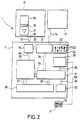
- the transducer 1 is shown in the form of logical function groups.
- the senor 1 comprises three modules 10, 11 and 12.
- the module 10 is designed as a sensor module. Inside is a sensor 15, such as. B. an acceleration sensor, connected via a connecting line 16 to a measuring amplifier 17. With the help of a plug 18, the sensor module 10 can be connected to the memory module 11.
- the plug 13/18 is connected to an A / D converter 19.
- the measured values recorded and processed by the A / D converter 19 can be transmitted to a memory module 25 via a connection 26. This is designed so that data can be read and read.
- the A / D converter 19 is connected to a threshold trigger 21 via a further connecting line 20.
- the corresponding threshold value can be set in the threshold value specification 22.
- This has a number of dip switches 23 which are adjustable along guides 24.
- An external trigger module 12 can be connected to the threshold trigger 21 via a trigger interface 14. When this module is connected, the threshold trigger 21 has no effect. The recording is then started by the external trigger module 12.
- An external trigger module 12 is also able to start several memory modules 11 at the same time.
- the threshold trigger 21 is additionally connected to a central unit 31 via a connection 34 contains both an address decoder and a unit for writing or reading the devices connected to it. It is also connected via a connection 35 to the memory component 25, via a connection 30 to a time base 29, via a connection 36 to a reset switch 32 and via a connection to a computer interface 28. With the help of the connection 33, the central unit 31 also controls the data flow of measured values along the connection 27 between the memory module 25 and the computer interface 28 via the computer interface 28.
- the time base 29 clocks the central unit 31 and the component connected to it via the connection 30 and thus determines the polling clock of the measurement data recorded by the sensor 15.
- a time base specification 70 is connected to the time base 29 via a connection 69. Similar to the threshold value specification 22, this has a number of dip switches 71. The position of the dip switches 71 determines the polling cycle of the time base 29.
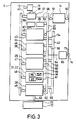
- FIG. 3 shows an embodiment of the memory module 11 in processor technology in principle. Parts which correspond to parts from FIG. 2 are provided with the same reference symbols.
- the memory module 11 essentially blocks represented as rectangles are arranged in columns, which have a series of connections to buses running along their shorter sides of the rectangle.
- the A / D converter 19 is connected to the plug 13/18 for converting the analog signals into digital signals.
- a release module 37 is arranged between this and the data bus 39, which is connected via line 38 to the converter 19 or Line 42 is connected to the data bus 39.
- the measured values can only be forwarded via the data bus 39 when the enable module 37 enables them.
- the release module 37 is connected to a control bus 41 via a connecting line 68.
- the z. B. can be designed as an 8-bit wide data bus, the measured values can be transported to the memory chip 25 and buffered there.
- data bus 39 and memory module 25 are connected with the aid of connecting line 47.
- the memory chip (working memory 25) itself is a so-called random access memory chip (RAM). This can be written and read.
- the writing or reading process can be controlled by a microprocessor 43. This is connected both to the data bus 39 via a connection 45 and to a control bus 41 or address bus 40 via connections 53 and 54. To specify the time intervals in which the microprocessor 43 executes instructions, it is connected to the clock generator 66 via a further connection 67.
- a read-only memory 44 is arranged between the microprocessor 43 and the RAM module 25.
- the program for the microprocessor is stored in this.
- the read-only memory 44 is connected to the control bus 41 by a selection line 57.
- connections 56 and 46 to the address bus 40 and to the data bus 39 are provided.
- a corresponding selection line 60 is also formed between the working memory 25 and the control bus 41.
- a write / read line 59 arranged parallel to the selection line 60 is between the Main memory 25 and the control bus 41 are arranged.
- an addressing connection 58 is arranged between the address bus 40 and the working memory 25.
- the setting unit 76 is arranged directly below the working memory 25. This encompasses both the switchable threshold value specification 22 and the time base specification 70 according to FIG. 2. For connection to the data bus 39 or the control bus 41, the threshold value specification 21, 22 is connected to these by connections 48 or selection line 61.
- An interface module 28 forms a module for regulating the input and output of data at the lower end of the column of the modules. For this purpose, it is connected to all buses via lines 49, 55 and 62. In addition, the connection to an evaluation unit 72 can be established via the connection 63. The lines 63 are routed to the outside of the sensor module 11, where they can be connected to a line 73 formed on the evaluation unit 72.
- the interface is designed as a so-called standard interface, which outputs and receives data serially or in parallel, depending on the type of training.
- the time base 29 is arranged adjacent to the system timer 66. This is connected to the control bus 41 via a clock line 52 and is used in connection with the time base specification 70 or a time base previously transmitted by the evaluation unit 72 to determine the clock in which the central unit uses the release module 37 to access A / D data -Converters 19 accesses.
- a trigger interface 14 is connected to the control bus 41 via a connecting line 51. Connected to this are the lines 50 which are routed to the outside of the memory module 11 and are used for connection to the external trigger module 12 shown in FIG. In addition, the polling clock can be queried from the time base via the control bus 41 via lines 51 and 50.
- a module voltage supply 65 is arranged within the memory module 11. This is connected to the control bus 41 by means of a line 64 and supplies both all components of the memory module as well as the components of possibly externally connected further modules. To switch on the memory module 11, the module voltage supply 65 is connected via a line 75 to a switch 74 which can be reached from the outside of the memory module 11.
- the arrow direction indicates the direction of the data transfer in all arrow-shaped connecting lines.
- the threshold value specification 22 it is only possible to query the threshold value via the data bus 39 and the connecting line 48.
- the working memory 25 via the data bus 39 both receives and outputs data and can be addressed via the connecting line 58 to the address bus 40 by the microprocessor 43.
- the microprocessor 43 initiates the reading in of the threshold value and of the query clock for the time base 29. This is done via the interface 28 from the evaluation unit 72 connected to it. If no values for the threshold value and the polling cycle are read in, so that the evaluation unit 72 is not connected, the values apply by which the corresponding dip switch devices 22 and 70 are set.
- the microprocessor 43 queries the A / D converter 19 in the polling cycle.
- an external trigger module is active, i. H. connected to the trigger module interface 14, this specifies a threshold value. Otherwise, the threshold value is queried from the threshold value specification 22 or the threshold values previously transmitted by the computer are used. The measured values queried by the A / D converter 19 are compared with the corresponding threshold value specification and as soon as a measured value is in a predetermined relation (equal, smaller, larger) to the threshold value, the recording in the working memory 25 is started.
- All data is stored in the main memory until it is full or until a query from the evaluation unit 72 is made via the interface 28. If the working memory is full before a corresponding request is made by the evaluation unit 72, the microprocessor remains in the waiting position until the required request is made or the memory module 11 is switched off. An inquiry is made to the Interface 28, the content of the working memory 25 is transmitted to the requesting evaluation unit 72 via the connections 63 and 73.
Landscapes
- Physics & Mathematics (AREA)
- General Physics & Mathematics (AREA)
- Engineering & Computer Science (AREA)
- Automation & Control Theory (AREA)
- Computer Networks & Wireless Communication (AREA)
- Indicating And Signalling Devices For Elevators (AREA)
- Maintenance And Inspection Apparatuses For Elevators (AREA)
- Forklifts And Lifting Vehicles (AREA)
- Investigating Or Analyzing Materials By The Use Of Fluid Adsorption Or Reactions (AREA)
Description
- Die Erfindung betrifft einen Meßwertaufnehmer zum Erfassen physikalischer Kenngrößen, insbesondere vom Beschleunigungswert, eines Personen- und/oder Lastenaufzugs mit zumindest einem bewegbaren Fahrkorb, wobei der Meßwertaufnehmer einen Sensor und einen diesem zugeordneten Zeitgeber umfaßt und über einen Schhittstellenbaustein mit einer Auswerteeinheit verbindbar ist.
- Die Ermittlung solcher Kenngroßen, wie z. B. der Beschleunigung, ist für die regelmäßige Kontrolle von Personen- und Lastenaufzügen unabdingbar. Bei einer aus der EP 0 390 972 A1 bekannten Vorrichtung zur Meßwertaufnahme werden ein oder mehrere Wegaufnehmer als Bewegungssensoren an einem Tragseil angeordnet und so die Geschwindigkeit, Geschwindigkeitsänderungen oder auch die Rutschfestigkeit des von der Treibscheibe angetriebenen Seilzugs ermittelt. Außerdem können auf diese Weise während des Fangvorgangs durch eine mit den Wegaufnehmern in Verbindung stehende Auswerteeinheit und eines entsprechenden Zeitgebers Weg-/Zeitkurven aufgenommen werden, um Aussagen über die Wirksamkeit der Fangvorrichtung Tragseil machen zu können.
- Nachteilig bei dieser vorbekannten Vorrichtung ist, daß bei bestimmten Aufzugsarten, wie z. B. bei indirekten hydraulischen Aufzügen mit Bremsfangvorrichtung die Abtastung so nicht möglich ist.
- Der Erfindung liegt daher die Aufgabe zugrunde, einen Meßwertaufnehmer der eingangs genanntent Art im Hinblick auf eine einfache Handhabung und vielfältige Einsatzmöglichkeiten unabhängig von den speziellen Eigenschaften des Aufzugs zu verbessern.
- Diese Aufgabe wird bei einem Meßwertaufnehmer mit den Merkmalen des Oberbegriffs des Anspruchs 1 dadurch gelöst, daß der Meßwertaufnehmer als transportable, an dem Fahrkorb lösbar befestigte Meßeinheit ausgebildet ist, und einen Zwischenspeicher und einen eine Meßwerterfassung und -speicherung auslösenden Triggerbaustein umfaßt. Gemäß der Erfindung ist so in besonders einfacher Weise z. B. ein Beschleunigungsmesser direkt an dem Fahrkorb, oder dem Gegengewicht sowohl außerhalb als auch innerhalb des Fahrkorbs, befestigbar. Durch den integrierten Zwischenspeicher werden alle Meßwerte während des Meßvorgangs zwischengespeichert. Der Beginn der Meßwertaufzeichnung sowie die entsprechende Meßwertspeicherung erfolgt ab einem bestimmten Wert der Beschleunigung, der durch den Triggerbaustein vorgegeben ist. Auf diese Weise erhält man ein genaues Abbild der Beschleunigung über die Zeit während z. B. des Fangvorgangs. Die Zeitachse wird durch den entsprechenden Zeitgeber realisiert. Nach dem Meßvorgang wird der Meßwertaufnehmer vom Fahrkorb entfernt und mit der Auswerteinheit verbunden.
- Wurde ein Fangvorgang aufgezeichnet, so läßt sich aus der Verzögerung des leeren Fahrkorbes mit wirksamen Gegengewicht auf die Verzögerung des mit Nennlast beladenen Fahrkorbes im Freifall umrechnen.
- War die Verzögerung über 1g (was sich aus der Aufzeichnung leicht ersehen läßt), so kommt es zu einem Springen des Gegengewichtes. Der Fahrkorb wirkt also folglich nur auf die Fangvorrichtung ohne Beeinflussung des Gegengewichtes. Im Verhältnis Fahrkorbmasse zu Fahrkorbmasse und Nennlast wird nun die Verzögerung von aleer auf aNennlast umgerechnet.
- Man kann folglich feststellen, wi der mit Nennlast beladene Fahrkorb im Katastrophenfall (Seilriß) verzögern würde.
- Auf diese Weise ist der Meßwertaufnehmer unabhängig von der Auswerteeinheit einsetzbar. Aufwendige Verbindungen zwischen beiden sind unnötig. Auch wäre ein Verbleiben der Auswerteeinheit (Rechner) während des Fangvorgangs nicht ratsam, da die hohen Verzögerungen diesen zerstören könnten. Unabhängig von der Aufzugsart und dessen Antrieb ist der erfindungsgemäße Meßwertaufnehmer vielfältig einsetzbar.
- Um einen universellen Einsatz des Meßwertaufnehmers zu ermöglichen, ist es günstig, wenn der Meßwertaufnehmer aus einem aus dem Sensor gebildeten Sensormodul und einem mit diesem verbindbaren, wenigstens den Zwischenspeicher umfassenden Speichermodul gebildet ist. Auf diese Weise ist das Sensormodul in einfacher Weise austauschbar, so daß z. B. statt eines Sensors für Beschleunigungswerte ein Sensor zur Messung von auftretenden Kräften während der Aufzugsbewegung angeschlossen werden kann.
- Die Verbindung zwischen Sensormodul und Speichermodul ist als direkte Steckverbindung ausgebildet.
- Bei einer vorteilhaften Weiterbildung der Erfindung ist ein dem Sensor zugeordneter Meßverstärker im Sensormodul angeordnet. Eine nachträgliche Verstärkung der Meßsignale ist somit überflüssig und die Signale können direkt gespeichert bzw. von der Auswerteeinheit verarbeitet werden.
- Weiterhin ist es günstig, wenn der Triggerbaustein und der Zeitgeber im Speichermodul angeordnet sind. Dadurch ist der gesamte Meßwertaufnehmer sehr kompakt und leicht handhabbar. Der Zeitgeber kann z. B. als integrierter Quarzzeitgeber ausgebildet sein. Zur Umwandlung der analogen Signale des Sensors in digitale Signale ist vorzugsweise ein A/D-Wandler im Speichermodul angeordnet und mit dem Meßverstärker verbunden. Auf diese Weise ist das Speichermodul vielseitig einsetzbar und kann mit jedem Analogsignalgeber verbunden werden.
- Um den Beginn der Aufzeichnung bei beliebigen Meßwerten zu starten bzw. zu stoppen, ist es von Vorteil, wenn der Triggerbaustein als variabler Schwellwerttrigger ausgebildet ist.
- In diesem Zusammenhang ist es weiterhin günstig, wenn Schwellwertdipschalter zur Schwellwerteinstellung dem Schwellwerttrigger zugeordnet sind. Mit Hilfe der Dipschalter ist eine einfache Einstellung des Triggers möglich, wobei die Schwellwerte in weitem Rahmen wählbar sein können.
- Um eine zufällige Verstellung des Schwellwerts z. B. bei einem Einbau des Speichermoduls im Fahrkorb zu verhindern, ist es weiterhin günstig, wenn die Schwellwertdipschalter im Speichermodul angeordnet sind, jedoch so, daß sie über Bohrungen im Gehäuse von außen verstellt werden können.
- Um die Einsatzmöglichkeiten des erfindungsgemäßen Meßwertaufnehmern zu erweitern, ist es von Vorteil, wenn ein den Schwellwerttrigger außer Kraft setzendes, externes Triggermodul mit dem Speichermodul über eine Triggerschnittstelle verbunden ist. Man ist somit in der Lage, z. B. durch Aufstecken des Triggermoduls die interne Schwellwerttriggerung abzuschalten und statt dessen durch einen von außen iniziierten Zeitpunkt die Aufzeichnung zu starten. Als Triggermodule sind beispielsweise Funkmodule, Infrarotmodule, Zeitmodule oder Schaltmodule denkbar. Diese sind über entsprechende, von außen kommende Signale einschaltbar und lösen den Meßvorgang aus.
- Außerdem ist es günstig, wenn das Triggermodul mit mehreren Meßwertaufnehmern verbunden ist. Auf diese Weise lassen sich mehrere Meßwertaufnehmer über die Triggerschnittstelle koppeln und eine mehrkanalige Aufzeichnung ist möglich. Ein Beispiel für eine mehrkanalige Aufzeichnung wäre z. B. die Messung von Beschleunigungen in allen drei Raumrichtungen.
- Bei einer weiteren vorteilhaften Ausführungsform ist der Zeitgeber mit einer variablen Zeitbasis bzw. Abfragetakt ausgebildet. Durch eine Änderung der Zeitbasis besteht die Möglichkeit, nicht nur sehr schnell ablaufende Vorgänge, sondern auch z. B. Fahrkurven eines Aufzugs aufzuzeichnen. Als Aufzeichnungszeiträume sind Sekunden bis zu Tagen mit einer Aufzeichnungsdichte von z. B. 10 000 Messungen pro Sekunde bis 30 Messungen pro Minute denkbar.
- Dabei ist es insbesondere günstig, wenn dem Zeitgeber zur Änderung der Zeitbasis bzw. des Abfragetakts Zeitdipschalter zugeordnet sind. So ist eine einfache Einstellung der Zeitbasis gegeben, wobei gleichzeitig die Stellung der Dipschalter als Anzeige für die eingestellte Zeitbasis nutzbar ist.
- Auch diese Dipschalter sind im Speichermodul angeordnet und ebenso wie die Schwellwertschalter von außen zugänglich.
- Um das Speichermodul in einfacher Weise und mit einer Vielzahl von Auswerteeinheiten verbinden zu können, ist es günstig, wenn der Schnittstellenbaustein im Speichermodul angeordnet ist, und als Standardschnittstelle ausgebildet ist. Auf diese Weise ist die Abfrage des Speichers vereinfacht und gleichzeitig kann die Auswerteeihheit ein fast beliebiger Computer sein, der über eine entsprechende Schnittstelle verfügt.
- Durch eine entsprechende Programmierung der Auswerteeinheit ist es weiterhin vorteilhaft möglich, die Auswerteeinheit zur Voreinstellung von Schwellwerttrigger und/oder Zeitgeber zu nutzen, sowie zum Abrufen der gespeicherten Meßwerte über den Schnittstellehbaustein mit dem Speichermodul zu verbinden. In diesem Fall sind die entsprechenden Dipschalter außer Kraft gesetzt, und die Einstellung von Schwellwert und Zeitbasis erfolgt durch die Auswerteeinheit direkt. Die Standardschnittstelle kann eine übliche RS-232 oder Centroniosschnittstelle sein. Die Auswerteeinheit ist mit entsprechender Software in der Lage, die aufgezeichneten Werte auszulesen und entsprechend weiterzuverarbeiten. Es ist z. B. eine graphische Darstellung der Meßwerte möglich, an der z. B. mittels eines Cursors Marken gesetzt werden können, die dann zu einer entsprechenden Mittelwertberechnung herangezogen werden. Aufgrund dieser berechneten Werte läßt sich dann eine Aussage über die Wirksamkeit der Fangvorrichtung machen.
- Um das Speichermodul unabhängig von äußeren Spannungsquellen auszubilden, ist es weiterhin günstig, einen Modulspannungsversorger innerhalb und einen zugeordneten Schalter von außerhalb des Speichermoduls erreichbar anzuordnen. Bei der heutzutage üblichen Realisierung von Speichereinrichtungen, Triggern, Zeitgebern und dergleichen auf Halbleiterbasis ist z. B. eine Spannungsversorgung mit Hilfe von Batterien möglich.
- In diesem Zusammenhang ist es günstig, wenn die mit dem Speichermodul verbundenen Module auch an der Modulspannungsversorgung angeschlossen sind. Über die entsprechenden Verbindungen der Module werden so auch das Sensormodul bzw. das Triggermodul versorgt.
- Um eventuell noch gespeicherte Werte oder andere durch die Auswerteeinheit programmierte Werte, wie z. B. Zeitbasis und Schwellwert, bei einem neuen Einsatz des Meßwertaufnehmers zu löschen, ist es von Vorteil, wenn der Schalter der Spannungsversorgung zum Zurücksetzen der Module in den Ausgangszustand beim Einschalten als Resetschalter ausgebildet ist.
- Weiterhin erweist es sich als günstig, wenn ein Microprozessor zur Steuerung der Meßwertaufnahme und der Speicherung im Speichermodul angeordnet ist.
- Allgemein ist durch die Trennung von Sensor- und Speichermodul weiterhin die Möglichkeit gegeben, nicht nur Beschleunigungswerte, sondern beliebige andere Meßwerte von Sensoren zu erfassen. Auch ist der Einsatz des Meßwertaufnehmers natürlich nicht auf Aufzüge beschränkt sondern kann auch an Fahrzeugen oder anderen bewegten wie auch unbewegten Gegenständen eingesetzt werden. Ebenso kann das universelle Speichermodul mit Temperatur-, Beleuchtungsstärke-, Gassenor- oder Strahlungsmodulen verbunden werden.
- Die erfindungsgemäß vorgeschlagene Lösung und ein vorteilhaftes Ausführungsbeispiel davon wird im folgenden anhand der in der Zeichnung dargestellten Figuren weiter erläutert und beschrieben.
- Es zeigen:
- Figur 1
- einen Personen- bzw. Lastenaufzug mit dem erfindungsgemäßen Meßwertaufnehmer;
- Figur 2
- den erfindungsgemäßen Meßwertaufnehmer mit in prinzipieller logischer Darstellung, und
- Figur 3
- eine Ausführungsform des Speichermoduls in Prozessortechnik.
- In Figur 1 ist ein Meßwertaufnehmer 1 auf einer Oberseite 2 eines Fahrkorbs 3 dargestellt. Der Fahrkorb 3 ist über ein Seil 4 mit einem Gegengewicht 8 verbunden, das in etwa in gleicher Höhe wie der Fahrkorb angeordnet ist. Mit Hilfe einer Motor-Getriebe-Bremseneinheit 6 ist das Seil 4 mit Hilfe einer Treibscheibe 5 entweder in Richtung des Fahrkorbs 3 bzw. des Gegengewichts 8 bewegbar. Die Motor-Getriebe-Bremseneinheit 6 ist durch eine Decke 9 vom Fahrkorb getrennt, im allgemeinen im obersten Teil eines Gebäudes oder auf dessen Dach angeordnet. In der Decke 9 sind Öffnungen 7 zum Durchlaß des Seils 4 ausgebildet.
- In Figur 2 ist der Meßwertaufnehmer 1 in Form logischen Funktionsgruppen dargestellt.
- In der hier dargestellten Form umfaßt der Meßwertaufnehmer 1 drei Module 10, 11 und 12. Das Modul 10 ist als Sensormodul ausgebildet. In seinem Inneren ist ein Sensor 15, wie z. B. ein Beschleunigungssensor, uber eine Verbindungsleitung 16 mit einem Meßverstärker 17 verbunden. Mit Hilfe eines Steckers 18 ist das Sensormodul 10 am Speichermodul 11 anschließbar.
- Im Speichermodul ist der Stecker 13/18 mit einem A/D-Wandler 19 verbunden. Über eine Verbindung 26 sind die vom A/D-Wandler 19 aufgenommenen und verarbeiteten Meßwerte an einen Speicherbaustein 25 übertragbar. Dieser ist so ausgebildet, daß sowohl Daten aus- als auch eingelesen werden können.
- Über eine weitere Verbindungsleitung 20 ist der A/D-Wandler 19 mit einem Schwellwerttrigger 21 verbunden. Der entsprechende Schwellwert ist in der Schwellwertvorgabe 22 einstellbar. Diese weist eine Anzahl von Dipschaltern 23 auf, die entlang von Führungen 24 verstellbar sind. An dem Schwellwerttrigger 21 ist über eine Triggerschnittstelle 14 ein externes Triggermodul 12 anschließbar. Bei Anschluß dieses Moduls ist der Schwellwerttrigger 21 wirkungslos. Die Aufzeichnung wird dann vom externen Triggermodul 12 gestartet. Ein externes Triggermodul 12 ist auch in der Lage, mehrere Speichermodule 11 gleichzeitig zu starten.
- Der Schwellwerttrigger 21 ist zusätzlich über eine Verbindung 34 mit einer Zentraleinheit 31 verbunden, die sowohl einen Adressdecoder als auch eine Einheit zum Schreiben bzw. Lesen der mit ihr verbundenen Einrichtungen enthält. Sie ist außerdem über eine Verbindung 35 mit dem Speicherbauteil 25, über eine Verbindung 30 mit einer Zeitbasis 29, über eine Verbindung 36 mit einem Resetschalter 32 und über eine Verbindung mit einer Rechnerschnittstelle 28 verbunden. Mit Hilfe der Verbindung 33 steuert die Zentraleinheit 31 über die Rechnerschnittstelle 28 auch den Datenfluß von Meßwerten entlang die Verbindung 27 zwischen Speicherbaustein 25 und Rechherschnittstelle 28.
- Die Zeitbasis 29 taktet über die Verbindung 30 die Zentraleinheit 31 sowie die damit angeschlossenen Bauteil und bestimmt so den Abfragetakt der durch den Sensor 15 aufgenommenen Meßdaten. Mit der Zeitbasis 29 ist über eine Verbindung 69 eine Zeitbasisvorgabe 70 verbunden. Diese weist ähnlich der Schwellwertvorgabe 22 eine Anzahl von Dipschaltern 71 auf. Die Stellung der Dipschalter 71 bestimmt den Abfragetakt der Zeitbasis 29.
- In Figur 3 ist eine Ausführungsform des Speichermoduls 11 in Prozessortechnik prinzipiell dargestellt. Teile, die Teilen aus Figur 2 entsprechen, sind mit den gleichen Bezugszeichen versehen.
- Im Speichermodul 11 sind im wesentlichen als Rechtecke dargestellte Bausteine spaltenförmig angeordnet, die eine Reihe von Verbindungen zu entlang ihrer kürzeren Rechtecksseiten verlaufenden Bussen aufweisen. Mit dem Stecker 13/18 ist der A/D-Wandler 19 zur Umwandlung der analogen Signale in digitale Signale verbunden. Zwische diesem und dem Datenbus 39 ist ein Freigabebaustein 37 angeordnet, der über Leitung 38 mit dem Wandler 19 bzw. Leitung 42 mit dem Datenbus 39 verbunden ist. Nur bei Freigabe (enable) durch den Freigabebaustein 37 sind die Meßwerte über den Datenbus 39 weiterleitbar. Zum Auslösen der Freigabe ist der Freigabebaustein 37 über eine Verbindungsleitung 68 mit einem Steuerbus 41 verbunden.
- Über den Datenbus 39, der z. B. als 8-Bit breiter Datenbus ausgebildet sein kann, sind die Meßwerte zum Speicherbaustein 25 transportierbar und dort zwischenspeicherbar. Zu diesem Zweck sind Datenbus 39 und Speicherbaustein 25 mit Hilfe der Verbindungsleitung 47 verbunden. Der Speicherbaustein (Arbeitsspeicher 25) selbst ist ein sogenannter Speicherbaustein mit wahlfreiem Zugriff (RAM). Dieser kann beschrieben und gelesen werden.
- Der Schreib- bzw. Lesevorgang ist von einem Microprozessor 43 steuerbar. Dieser ist sowohl über eine Verbindung 45 mit dem Datenbus 39 als auch über Verbindungen 53 und 54 mit einem Steuerbus 41 bzw. Adressbus 40 verbunden. Zur Vorgabe der Zeitabstände, in denen der Microprozessor 43 Instruktionen ausführt, ist dieser über eine weitere Verbindung 67 mit dem Taktgeber 66 verbunden.
- Zwischen Microprozessor 43 und RAM-Baustein 25 ist ein Festwertspeicher 44 angeordnet. In diesem ist das Programm für den Microprozessor gespeichert. Durch eine Auswahlleitung 57 ist der Festwertspeicher 44 mit dem Steuerbus 41 verbunden. Zusätzlich sind Anschlüsse 56 und 46 zum Adressbus 40 bzw. zum Datenbus 39 vorhanden.
- Eine entsprechende Auswahlleitung 60 ist auch zwischen Arbeitsspeicher 25 und Steuerbus 41 ausgebildet. Zusätzlich ist eine zur Auswahlleitung 60 parallel angeordnete Schreib/Leseleitung 59 zwischen dem Arbeitsspeicher 25 und dem Steuerbus 41 angeordnet. Um den Arbeitsspeicher 25 mit Hilfe des Microprozessors 43 adressieren zu können, ist zwischen Adressbus 40 und Arbeitsspeicher 25 eine Adressierverbindung 58 angeordnet.
- Direkt unterhalb des Arbeitsspeichers 25 ist die Einstelleinheit 76 angeordnet. Diese umfaßt sowohl die schaltbare Schwellwertvorgabe 22 als auch die Zeitbasisvorgabe 70 gemäß Figur 2. Zur Verbindung mit dem Datenbus 39 bzw. dem Steuerbus 41 ist die Schwellwertvorgabe 21, 22 mit diesen durch Verbindungen 48 bzw. Auswahlleitung 61 verbunden.
- Ein Schnittstellenbaustein 28 bildet am unteren Ende der Spalte der Bausteine einen Baustein zur Regelung der Eingabe bzw. Ausgabe von Daten. Dazu ist dieser mit allen Bussen über Leitungen 49, 55 und 62 verbunden. Außerdem ist über die Verbindung 63 der Kontakt zu einer Auswerteinheit 72 herstellbar. Die Leitungen 63 sind bis zur Außenseite des Sensormoduls 11 durchgeführt, wo sie mit einer an der Auswerteinheit 72 ausgebildeten Leitungen 73 verbindbar sind. Die Schnittstelle ist als sogenannte Standardschnittstelle ausgebildet, die Daten je nach Ausbildungsform seriell bzw. parallel ausgibt und empfängt.
- Benachbart zum Systemzeitgeber 66 ist die Zeitbasis 29 angeordnet. Diese ist über eine Taktleitung 52 mit dem Steuerbus 41 verbunden und dient dazu, in Verbindung mit der Zeitbasisvorgabe 70 bzw. einem vorher von der Auswerteeinheit 72 übermittelten Zeitbasis den Takt festzulegen, in welchem die Zentraleinheit mit Hilfe des Freigabebausteins 37 auf Daten des A/D-Wandlers 19 zugreift.
- Außerdem ist mit dem Steuerbus 41 über eine Verbindungsleitung 51 eine Triggerschnittstelle 14 verbunden. Mit dieser sind die Leitungen 50 verbunden, die bis an die Außenseite des Speichermoduls 11 durchgeführt sind und zur Verbindung mit dem in Figur 2 dargestellten externen Triggermodul 12 dienen. Über die Leitung 51 und 50 ist außerdem der Abfragetakt über den Steuerbus 41 von der Zeitbasis abfragbar herausgeführt.
- Zur Versorgung aller Bauelemente mit der notwendigen Spannung ist innerhalb des Speichermoduls 11 eine Modulspannungsversorgung 65 angeordnet. Diese ist mit Hilfe einer Leitung 64 mit dem Steuerbus 41 verbunden und versorgt sowohl alle Bausteine des Speichermoduls als auch die Bausteine von möglicherweise extern angeschlossenen, weiteren Modulen. Zum Einschalten des Speichermoduls 11 ist die Modulspannungsversorgung 65 über eine Leitung 75 mit einem von der Außenseite des Speichermoduls 11 erreichbaren Schalter 74 verbunden.
- Allgemein ist bei der Darstellung gemäß Figur 3 zu beachten, daß bei allen pfeilförmig zulaufenden Verbindungsleitungen die Pfeilrichtung die Richtung des Datentransfers kennzeichnet. So ist z. B. bezüglich der Schwellwertvorgabe 22 nur ein Abfragen des Schwellwertes über den Datenbus 39 und die Verbindungsleitung 48 möglich. Während z. B. der Arbeitsspeicher 25 über den Datenbus 39 sowohl Daten aufnimmt als auch abgibt und über die Verbindungsleitung 58 zum Adressbus 40 vom Microprozessor 43 angesprochen werden kann.
- Im folgenden wird das Zusammenwirken der einzelnen Bausteine beschrieben.
- Nach dem Einschalten des Speichermcduls 11 mit Hilfe des Schalters 74 wird durch den Microprozessor 43 das Einlesen des Schwellwerts sowie des Abfragetaktes für die Zeitbasis 29 veranlaßt. Dies geschieht über die Schnittstelle 28 aus der mit dieser verbundenen Auswerteeinheit 72. Werden keine Werte für Schwellwert und Abfragetakt eingelesen, die Auswerteeinheit 72 also nicht angeschlossten ist, so gelten die Werte, durch die entsprechenden Dipschaltereinrichtungen 22 und 70 eingestellt sind.
- Falls an dem Stecker 13/18 ein entsprechendes Sensormodul 10 angeschlossen ist, fragt der Microprozessor 43 im Abfragetakt den A/D-Wandler 19 ab.
- Ist ein externes Triggermodul aktiv, d. h. mit der Triggermodulschnittstelle 14 verbunden, so gibt dieses einen Schwellwert vor. Andernfalls wird der Schwellwert aus der Schwellwertvorgabe 22 abgefragt, bzw. die vorher vom Rechner übermittelten Schwellwerte eingesetzt. Die von dem A/D-Wandler 19 abgefragten Meßwerte werden mit der entsprechenden Schwellwertvorgabe verglichen und sobald ein Meßwert in einer vorbestimmten Relation (gleich, kleiner, größer) zum Schwellwert ist, wird die Aufzeichnung in den Arbeitsspeicher 25 gestartet.
- Alle Daten werden im Arbeitsspeicher gespeichert, solange bis dieser voll ist bzw. bis über die Schnittstelle 28 eine Anfrage der Auswerteeinheit 72 erfolgt. Falls der Arbeitsspeicher voll ist, bevor eine entsprechende Anfrage durch die Auswerteeinheit 72 erfolgt, so bleibt der Microprozessor solange in Warteposition, bis die erforderliche Anfrage erfolgt, bzw. das Speichermodul 11 abgeschaltet wird. Erfolgt eine Anfrage an die Schnittstelle 28, so wird der Inhalt des Arbeitsspeichers 25 an die anfragende Auswerteeinheit 72 über die Verbindungen 63 und 73 übertragen.
Claims (9)
- Meßwertaufnehmer (1) zum Erfassen physikalischer Kenngrößen, insbesondere von Beschleunigungswerten, eines Personen- und/oder Lastenaufzugs mit zumindest einem bewegbarem Fahrkorb (3), wobei der Meßwertaufnehmer (1) einen Sensor (15) und einen diesem zugeordneten Zeitgeber (29) umfaßt und über einen Schnittstellenbaustein (28) mit einer Auswerteeinheit (72) verbindbar ist, dadurch gekennzeichnet, daß der Meßwertaufnehmer (1) als transportable, an dem Fahrkorb lösbar befestigte Meßeinheit (10, 11, 12) ausgebildet ist und einen Zwischenspeicher (25) und einen die Meßwerterfassung und -speicherung auslösenden Triggerbaustein (21) umfaßt.
- Meßwertaufnehmer nach Anspruch 1, dadurch gekennzeichnet, daß der Meßwertaufnehmer (1) aus einem aus dem Sensor gebildeten Sensormodul (10) und einem mit diesem verbindbaren, wenigstens den Zwischenspeicher (25) umfassenden Speichermodul (11) gebildet ist.
- Meßwertaufnehmer nach wenigstens einem der vorangehenden Ansprüche, dadurch gekennzeichnet, daß der Triggerbaustein (21) als variabler Schwellwerttrigger ausgebildet ist.
- Meßwertaufnehmer nach Anspruch 3, dadurch gekennzeichnet, daß Schwellwertdipschalter (23) zur Schwellwerteinstellung dem Schwellwerttrigger (21) zugeordnet sind.
- Meßwertaufnehmer nach wenigstens einem der vorangehenden Ansprüche, dadurch gekennzeichnet, daß ein den Schwellwerttrigger (21) außer Kraft setzendes, externes Triggermodul (12) mit dem Speichermodul (11) über eine Triggerschnittstelle (14) verbunden ist.
- Meßwertaufnehmer nach Anspruch 5, dadurch gekennzeichnet, daß das Triggermodul (12) mit mehreren Meßwertaufnehmern (1) verbunden ist.
- Meßwertaufnehmer nach wenigstens einem der vorangehenden Ansprüche, dadurch gekennzeichnet, daß der Zeitgeber (29) mit einer variablen Zeitbasis bzw. Abfragetakt ausgebildet ist.
- Meßwertaufnehmer nach wenigstens einem der vorangehenden Ansprüche, dadurch gekennzeichnet, daß die Auswerteeinheit (72) zur Voreinstellung von Schwellwerttrigger und/oder Zeitgeber (29) sowie zum Abrufen der gespeicherten Meßwerte über einen Schnittstellenbaustein (28) mit dem Speichermodul (11) verbunden ist.
- Meßwertaufnehmer nach Anspruch 8, dadurch gekennzeichnet, daß die mit dem Speichermodul (11) verbundenen Module (10, 12) an einer Modulspannungsversorgung (65) angeschlossen sind.
Applications Claiming Priority (3)
| Application Number | Priority Date | Filing Date | Title |
|---|---|---|---|
| DE9015495U | 1990-11-12 | ||
| DE9015495U DE9015495U1 (de) | 1990-11-12 | 1990-11-12 | |
| PCT/EP1991/002131 WO1992008665A1 (de) | 1990-11-12 | 1991-11-11 | Messwertaufnehmer zum erfassen physikalischer kenngrössen eines personen- und/oder lastenaufzugs |
Publications (2)
| Publication Number | Publication Date |
|---|---|
| EP0573432A1 EP0573432A1 (de) | 1993-12-15 |
| EP0573432B1 true EP0573432B1 (de) | 1996-02-21 |
Family
ID=6859279
Family Applications (1)
| Application Number | Title | Priority Date | Filing Date |
|---|---|---|---|
| EP91919429A Expired - Lifetime EP0573432B1 (de) | 1990-11-12 | 1991-11-11 | Messwertaufnehmer zum erfassen physikalischer kenngrössen eines personen- und/oder lastenaufzugs |
Country Status (8)
| Country | Link |
|---|---|
| US (1) | US5522480A (de) |
| EP (1) | EP0573432B1 (de) |
| JP (1) | JPH06502376A (de) |
| AT (1) | ATE134356T1 (de) |
| DE (2) | DE9015495U1 (de) |
| ES (1) | ES2087312T3 (de) |
| GR (1) | GR3019068T3 (de) |
| WO (1) | WO1992008665A1 (de) |
Cited By (7)
| Publication number | Priority date | Publication date | Assignee | Title |
|---|---|---|---|---|
| DE102005004667A1 (de) * | 2005-02-02 | 2006-08-10 | TÜV Nord GmbH | Diagnoseeinrichtung |
| DE102006011092A1 (de) * | 2006-03-08 | 2007-09-13 | TÜV Rheinland Industrie Service GmbH | Prüfhebel mit Auflager |
| DE102006011395A1 (de) * | 2006-03-09 | 2007-09-13 | TÜV Rheinland Industrie Service GmbH | Messvorrichtung für eine Treibfähigkeitsmessung |
| DE102006011093A1 (de) * | 2006-03-08 | 2007-09-13 | TÜV Rheinland Industrie Service GmbH | Seilschlupf-Detektor |
| DE102007009602A1 (de) | 2007-02-26 | 2008-08-28 | TÜV Rheinland Industrie Service GmbH | Treibfähigkeitsmessung an Treibscheibenaufzugsanlagen |
| DE102008022416A1 (de) | 2008-05-06 | 2009-11-12 | TÜV Rheinland Industrie Service GmbH | Beschleunigungsmessung an einer Aufzugseinrichtung |
| DE102009001056A1 (de) | 2009-02-20 | 2010-09-02 | Dekra Testing & Inspection Gmbh | Verfahren zur Prüfung der ordnungsgemäßen Funktionsfähigkeit eines Aufzugs |
Families Citing this family (24)
| Publication number | Priority date | Publication date | Assignee | Title |
|---|---|---|---|---|
| DE4217587C2 (de) * | 1992-05-21 | 1999-02-25 | Ernst Dipl Ing Kasten | Anlagen-Diagnoseverfahren |
| JPH09110326A (ja) * | 1995-07-31 | 1997-04-28 | Otis Elevator Co | エレベータかごの制御方法およびエレベータの制御機構 |
| DE10150284A1 (de) * | 2001-10-12 | 2003-04-30 | Henning Gmbh | Diagnoseeinrichtung und Verfahren zur Diagnose von Aufzugsanlagen |
| DE10306375B3 (de) * | 2003-02-15 | 2004-10-14 | Henning Gmbh | Verfahren zur Überprüfung von Fangvorrichtungen |
| ITPN20030015A1 (it) * | 2003-02-26 | 2004-08-27 | Stem Srl | Dispositivo di controllo alimentato elettricamente |
| DE10323175A1 (de) | 2003-05-22 | 2004-12-23 | TÜV Industrie Service GmbH - TÜV Rheinland Group | Prüfhebel |
| US7004289B2 (en) * | 2003-09-30 | 2006-02-28 | Shrum Iii William M | Elevator performance measuring device and method |
| JP4550448B2 (ja) * | 2004-03-02 | 2010-09-22 | 東芝エレベータ株式会社 | 昇降機の計測装置 |
| PL2189410T3 (pl) * | 2004-06-02 | 2014-05-30 | Inventio Ag | Nadzorowanie windy |
| DE102004060006A1 (de) * | 2004-12-14 | 2006-07-06 | TÜV Industrie Service GmbH - TÜV Rheinland Group | Multifunktionaler Drucksensor und zugehöriges Verfahren |
| FI118466B (fi) * | 2005-04-08 | 2007-11-30 | Kone Corp | Kunnonvalvontajärjestelmä |
| DE102006036251A1 (de) * | 2006-08-03 | 2008-02-07 | TÜV Rheinland Industrie Service GmbH | Seilrutsch / Treibfähigkeits-Indikator |
| DE102007021196B4 (de) | 2007-05-05 | 2013-09-05 | Thomas Harzbecker | Selbsttätige Brems- und Fangvorrichtung, insbesondere für Freifallanlagen mit rückspringendem Fallkorb |
| WO2009010410A1 (de) * | 2007-07-17 | 2009-01-22 | Inventio Ag | Überwachungsverfahren einer aufzugsanlage |
| CN102348625B (zh) * | 2009-03-16 | 2015-08-26 | 奥的斯电梯公司 | 过加速和过速检测与处理系统 |
| US8893858B2 (en) * | 2010-06-29 | 2014-11-25 | Empire Technology Development Llc | Method and system for determining safety of elevator |
| FI122598B (fi) * | 2011-04-01 | 2012-04-13 | Kone Corp | Menetelmä hissijärjestelmän toimintakunnon valvomiseksi |
| EP2604564A1 (de) * | 2011-12-14 | 2013-06-19 | Inventio AG | Fehlerdiagnose einer Aufzuganlage und seiner Komponenten mittels Sensor |
| WO2014200457A1 (en) * | 2013-06-10 | 2014-12-18 | Otis Elevator Company | Elevator noise monitoring |
| US10112801B2 (en) | 2014-08-05 | 2018-10-30 | Richard Laszlo Madarasz | Elevator inspection apparatus with separate computing device and sensors |
| EP3103537B1 (de) * | 2015-06-09 | 2018-12-19 | Robert Bosch Gmbh | Verfahren und messsystem zur diagnose von einrichtungen zum befördern von lasten, verwendung des messsystems |
| EP3002245A3 (de) * | 2015-10-05 | 2016-04-27 | Raw Tech, S.L. | Erkennung und übertragung system der status und der position einer aufzugskabine |
| US10547917B2 (en) | 2017-05-12 | 2020-01-28 | Otis Elevator Company | Ride quality mobile terminal device application |
| CN109534122B (zh) * | 2019-01-11 | 2023-07-21 | 福建省特种设备检验研究院 | 一种电梯运行质量测试仪 |
Family Cites Families (16)
| Publication number | Priority date | Publication date | Assignee | Title |
|---|---|---|---|---|
| NZ190374A (en) * | 1978-05-10 | 1982-08-17 | Res Analysis & Dev | Aircraft structure deflection measurement and detection |
| JPS5511418A (en) * | 1978-07-07 | 1980-01-26 | Hitachi Ltd | Test operating apparatus of elevator |
| US4418795A (en) * | 1981-07-20 | 1983-12-06 | Westinghouse Electric Corp. | Elevator servicing methods and apparatus |
| US4401192A (en) * | 1981-10-06 | 1983-08-30 | Westinghouse Electric Corp. | Method of evaluating the performance of an elevator system |
| US4561093A (en) * | 1983-02-22 | 1985-12-24 | Otis Elevator Company | Servicing a software-controlled elevator |
| GB2146776B (en) * | 1983-09-16 | 1986-07-30 | Ferranti Plc | Accelerometer systems |
| US4512442A (en) * | 1984-03-30 | 1985-04-23 | Westinghouse Electric Corp. | Method and apparatus for improving the servicing of an elevator system |
| FI72947C (fi) * | 1985-09-27 | 1987-08-10 | Kone Oy | Foerfarande och anordning foer kontinuerlig kompensering av en hisskorgs horisontala kast. |
| US4798267A (en) * | 1987-01-20 | 1989-01-17 | Delaware Capital Formation, Inc. | Elevator system having an improved selector |
| FI76768C (fi) * | 1987-05-27 | 1988-12-12 | Kone Oy | Foerfarande foer bestaemning av en hiss' position samt en pulsvaoningsraeknare. |
| US4750591A (en) * | 1987-07-10 | 1988-06-14 | Otis Elevator Company | Elevator car door and motion sequence monitoring apparatus and method |
| US4874063A (en) * | 1988-10-27 | 1989-10-17 | Otis Elevator Company | Portable elevator traffic pattern monitoring system |
| DE3911391C5 (de) * | 1989-04-07 | 2010-04-29 | TÜV SÜD Industrie Service GmbH | Verfahren und Vorrichtung zum Überprüfen der Treibfähigkeit |
| DE8904375U1 (de) * | 1989-04-07 | 1989-07-27 | Tuev Bayern E.V., 8000 Muenchen, De | |
| US5400872A (en) * | 1990-07-18 | 1995-03-28 | Otis Elevator Company | Counteracting horizontal accelerations on an elevator car |
| US5402863A (en) * | 1991-05-29 | 1995-04-04 | Mitsubishi Denki Kabushiki Kaisha | Apparatus to automatically adjust spring tension of an elevator brake to maintain brake torque |
-
1990
- 1990-11-12 DE DE9015495U patent/DE9015495U1/de not_active Expired - Lifetime
-
1991
- 1991-11-11 AT AT91919429T patent/ATE134356T1/de not_active IP Right Cessation
- 1991-11-11 JP JP3517376A patent/JPH06502376A/ja active Pending
- 1991-11-11 DE DE59107439T patent/DE59107439D1/de not_active Expired - Lifetime
- 1991-11-11 ES ES91919429T patent/ES2087312T3/es not_active Expired - Lifetime
- 1991-11-11 WO PCT/EP1991/002131 patent/WO1992008665A1/de active IP Right Grant
- 1991-11-11 EP EP91919429A patent/EP0573432B1/de not_active Expired - Lifetime
-
1995
- 1995-08-16 US US08/515,691 patent/US5522480A/en not_active Expired - Lifetime
-
1996
- 1996-02-22 GR GR960400350T patent/GR3019068T3/el unknown
Cited By (8)
| Publication number | Priority date | Publication date | Assignee | Title |
|---|---|---|---|---|
| DE102005004667A1 (de) * | 2005-02-02 | 2006-08-10 | TÜV Nord GmbH | Diagnoseeinrichtung |
| DE102006011092A1 (de) * | 2006-03-08 | 2007-09-13 | TÜV Rheinland Industrie Service GmbH | Prüfhebel mit Auflager |
| DE102006011093A1 (de) * | 2006-03-08 | 2007-09-13 | TÜV Rheinland Industrie Service GmbH | Seilschlupf-Detektor |
| DE102006011395A1 (de) * | 2006-03-09 | 2007-09-13 | TÜV Rheinland Industrie Service GmbH | Messvorrichtung für eine Treibfähigkeitsmessung |
| DE102006011395B4 (de) * | 2006-03-09 | 2014-12-31 | TÜV Rheinland Industrie Service GmbH | Messvorrichtung für eine Treibfähigkeitsmessung |
| DE102007009602A1 (de) | 2007-02-26 | 2008-08-28 | TÜV Rheinland Industrie Service GmbH | Treibfähigkeitsmessung an Treibscheibenaufzugsanlagen |
| DE102008022416A1 (de) | 2008-05-06 | 2009-11-12 | TÜV Rheinland Industrie Service GmbH | Beschleunigungsmessung an einer Aufzugseinrichtung |
| DE102009001056A1 (de) | 2009-02-20 | 2010-09-02 | Dekra Testing & Inspection Gmbh | Verfahren zur Prüfung der ordnungsgemäßen Funktionsfähigkeit eines Aufzugs |
Also Published As
| Publication number | Publication date |
|---|---|
| GR3019068T3 (en) | 1996-05-31 |
| ATE134356T1 (de) | 1996-03-15 |
| DE9015495U1 (de) | 1992-01-02 |
| ES2087312T3 (es) | 1996-07-16 |
| WO1992008665A1 (de) | 1992-05-29 |
| EP0573432A1 (de) | 1993-12-15 |
| DE59107439D1 (de) | 1996-03-28 |
| JPH06502376A (ja) | 1994-03-17 |
| US5522480A (en) | 1996-06-04 |
Similar Documents
| Publication | Publication Date | Title |
|---|---|---|
| EP0573432B1 (de) | Messwertaufnehmer zum erfassen physikalischer kenngrössen eines personen- und/oder lastenaufzugs | |
| EP0391174B2 (de) | Vorrichtung und Verfahren zum Erfassen von physikalischen Kenngrössen eines Aufzuges | |
| EP0390972B1 (de) | Verfahren zum Erfassen von physikalischen Kenngrössen eines Aufzuges | |
| DE4136968C1 (de) | ||
| EP2329279B1 (de) | Verfahren und vorrichtung zur ermittlung eines bewegungszustands eines fahrzeugs mit einem beschleunigungssensor | |
| DE3038873C2 (de) | ||
| DE69725684T2 (de) | Verfahren und Vorrichtung zur Messung der Last einer Aufzugskabine | |
| DE10121693A1 (de) | Verfahren und Vorrichtung zum Detektieren des Kontakts von Händen mit dem Lenkrad | |
| WO1999050096A1 (de) | Insassenschutzsystem mit einer zentraleinheit, sensoren und mehreren mittels eines bus-systems kommunikationsfähig verbundenen steuermodulen zur auslösung von insassenschutzeinrichtungen | |
| DE2548236B2 (de) | Gleitweg-warngeraet | |
| DE102010010579A1 (de) | Stellplatz-Managementsystem für eine Parkeinrichtung | |
| DE3815626A1 (de) | Elektronische waage mit kalibriergewichtsschaltung | |
| EP0755894A1 (de) | Verfahren und Einrichtung zur Messung der Last in einer Aufzugskabine | |
| DE4016661A1 (de) | Antiblockiersystem | |
| EP0449845B2 (de) | Antiblockierregelsystem | |
| DE19814117C2 (de) | Unfallgeräusch-Detektor | |
| DE102015226699A1 (de) | Vorrichtung und Verfahren zur Erfassung wenigstens eines Bewegungsparameters einer triebwerksraumlosen Treibscheibenaufzugsanlage | |
| DE102005045233A1 (de) | Steuergerät für den Personenschutz | |
| CH670079A5 (de) | ||
| DE2151272A1 (de) | Steuerungssystem fuer eine Vielzahl von Lastaufnahmemitteln | |
| DE69633371T2 (de) | Korrekturlauf für ein Aufzugssystem | |
| EP0802467A2 (de) | Verfahren und Einrichtung zum Positionieren eines Gerätes | |
| DE3147158A1 (de) | "krantraverse fuer krantandembetrieb" | |
| WO2009135629A1 (de) | Beschleunigungsmessung an einer aufzugseinrichtung | |
| DE102013217879A1 (de) | Verfahren zum Überwachen einer Übertragungsstrecke |
Legal Events
| Date | Code | Title | Description |
|---|---|---|---|
| PUAI | Public reference made under article 153(3) epc to a published international application that has entered the european phase |
Free format text: ORIGINAL CODE: 0009012 |
|
| 17P | Request for examination filed |
Effective date: 19930329 |
|
| AK | Designated contracting states |
Kind code of ref document: A1 Designated state(s): AT CH DE DK ES FR GB GR IT LI NL SE |
|
| 17Q | First examination report despatched |
Effective date: 19950330 |
|
| GRAA | (expected) grant |
Free format text: ORIGINAL CODE: 0009210 |
|
| STAA | Information on the status of an ep patent application or granted ep patent |
Free format text: STATUS: THE PATENT HAS BEEN GRANTED |
|
| AK | Designated contracting states |
Kind code of ref document: B1 Designated state(s): AT CH DE DK ES FR GB GR IT LI NL SE |
|
| PG25 | Lapsed in a contracting state [announced via postgrant information from national office to epo] |
Ref country code: DK Effective date: 19960221 |
|
| REF | Corresponds to: |
Ref document number: 134356 Country of ref document: AT Date of ref document: 19960315 Kind code of ref document: T |
|
| GBT | Gb: translation of ep patent filed (gb section 77(6)(a)/1977) |
Effective date: 19960217 |
|
| REF | Corresponds to: |
Ref document number: 59107439 Country of ref document: DE Date of ref document: 19960328 |
|
| REG | Reference to a national code |
Ref country code: CH Ref legal event code: NV Representative=s name: ISLER & PEDRAZZINI AG PATENTANWAELTE |
|
| ITF | It: translation for a ep patent filed |
Owner name: PROPRIA PROTEZIONE PROPR. IND. |
|
| REG | Reference to a national code |
Ref country code: GR Ref legal event code: FG4A Free format text: 3019068 |
|
| PLBQ | Unpublished change to opponent data |
Free format text: ORIGINAL CODE: EPIDOS OPPO |
|
| PLBI | Opposition filed |
Free format text: ORIGINAL CODE: 0009260 |
|
| REG | Reference to a national code |
Ref country code: ES Ref legal event code: BA2A Ref document number: 2087312 Country of ref document: ES Kind code of ref document: T3 |
|
| ET | Fr: translation filed | ||
| 26 | Opposition filed |
Opponent name: TECHNISCHER UEBERWACHUNGS-VEREIN HANNOVER/SACHSEN- Effective date: 19950510 |
|
| REG | Reference to a national code |
Ref country code: ES Ref legal event code: FG2A Ref document number: 2087312 Country of ref document: ES Kind code of ref document: T3 |
|
| NLR1 | Nl: opposition has been filed with the epo |
Opponent name: TECHNISCHER UEBERWACHUNGS-VEREIN HANNOVER/SACHSEN- |
|
| REG | Reference to a national code |
Ref country code: CH Ref legal event code: PUE Owner name: TECHNISCHER UEBERWACHUNGS-VEREIN BAYERN HESSEN SAC Ref country code: CH Ref legal event code: PFA Free format text: TECHNISCHER UEBERWACHUNGS-VEREIN BAYERN SACHSEN E.V. TRANSFER- TECHNISCHER UEBERWACHUNGS-VEREIN BAYERN HESSEN SACHSEN E.V. |
|
| REG | Reference to a national code |
Ref country code: GB Ref legal event code: 732E |
|
| PLAB | Opposition data, opponent's data or that of the opponent's representative modified |
Free format text: ORIGINAL CODE: 0009299OPPO |
|
| R26 | Opposition filed (corrected) |
Opponent name: TECHNISCHER UEBERWACHUNGS-VEREIN HANNOVER/SACHSEN- Effective date: 19960510 |
|
| REG | Reference to a national code |
Ref country code: FR Ref legal event code: TP |
|
| REG | Reference to a national code |
Ref country code: ES Ref legal event code: PC2A |
|
| NLR1 | Nl: opposition has been filed with the epo |
Opponent name: TECHNISCHER UEBERWACHUNGS-VEREIN HANNOVER/SACHSEN- |
|
| PLBG | Opposition deemed not to have been filed |
Free format text: ORIGINAL CODE: 0009274 |
|
| 26D | Opposition deemed not to have been filed | ||
| NLS | Nl: assignments of ep-patents |
Owner name: TUEV BAU- UND BETRIEBSTECHNIK GMBH UNTERNEHMENSGRU |
|
| NLXE | Nl: other communications concerning ep-patents (part 3 heading xe) |
Free format text: PAT.BUL.09/96:THE OPPOSITION SHOULD BE DEEMED NOT TO HAVE BEEN FILED |
|
| PGFP | Annual fee paid to national office [announced via postgrant information from national office to epo] |
Ref country code: GR Payment date: 19981027 Year of fee payment: 8 |
|
| PGFP | Annual fee paid to national office [announced via postgrant information from national office to epo] |
Ref country code: AT Payment date: 19981028 Year of fee payment: 8 |
|
| PGFP | Annual fee paid to national office [announced via postgrant information from national office to epo] |
Ref country code: SE Payment date: 19981120 Year of fee payment: 8 |
|
| PGFP | Annual fee paid to national office [announced via postgrant information from national office to epo] |
Ref country code: CH Payment date: 19981207 Year of fee payment: 8 |
|
| PG25 | Lapsed in a contracting state [announced via postgrant information from national office to epo] |
Ref country code: AT Free format text: LAPSE BECAUSE OF NON-PAYMENT OF DUE FEES Effective date: 19991111 |
|
| PG25 | Lapsed in a contracting state [announced via postgrant information from national office to epo] |
Ref country code: SE Free format text: LAPSE BECAUSE OF NON-PAYMENT OF DUE FEES Effective date: 19991112 |
|
| PGFP | Annual fee paid to national office [announced via postgrant information from national office to epo] |
Ref country code: FR Payment date: 19991117 Year of fee payment: 9 |
|
| PGFP | Annual fee paid to national office [announced via postgrant information from national office to epo] |
Ref country code: NL Payment date: 19991123 Year of fee payment: 9 |
|
| PG25 | Lapsed in a contracting state [announced via postgrant information from national office to epo] |
Ref country code: LI Free format text: LAPSE BECAUSE OF NON-PAYMENT OF DUE FEES Effective date: 19991130 Ref country code: GR Free format text: LAPSE BECAUSE OF NON-PAYMENT OF DUE FEES Effective date: 19991130 Ref country code: CH Free format text: LAPSE BECAUSE OF NON-PAYMENT OF DUE FEES Effective date: 19991130 |
|
| REG | Reference to a national code |
Ref country code: CH Ref legal event code: PL |
|
| EUG | Se: european patent has lapsed |
Ref document number: 91919429.0 |
|
| PGFP | Annual fee paid to national office [announced via postgrant information from national office to epo] |
Ref country code: ES Payment date: 20001117 Year of fee payment: 10 |
|
| PG25 | Lapsed in a contracting state [announced via postgrant information from national office to epo] |
Ref country code: NL Free format text: LAPSE BECAUSE OF NON-PAYMENT OF DUE FEES Effective date: 20010601 |
|
| PG25 | Lapsed in a contracting state [announced via postgrant information from national office to epo] |
Ref country code: FR Free format text: LAPSE BECAUSE OF NON-PAYMENT OF DUE FEES Effective date: 20010731 |
|
| NLV4 | Nl: lapsed or anulled due to non-payment of the annual fee |
Effective date: 20010601 |
|
| REG | Reference to a national code |
Ref country code: FR Ref legal event code: ST |
|
| PG25 | Lapsed in a contracting state [announced via postgrant information from national office to epo] |
Ref country code: ES Free format text: LAPSE BECAUSE OF NON-PAYMENT OF DUE FEES Effective date: 20011112 |
|
| REG | Reference to a national code |
Ref country code: GB Ref legal event code: IF02 |
|
| REG | Reference to a national code |
Ref country code: ES Ref legal event code: FD2A Effective date: 20021213 |
|
| PG25 | Lapsed in a contracting state [announced via postgrant information from national office to epo] |
Ref country code: IT Free format text: LAPSE BECAUSE OF NON-PAYMENT OF DUE FEES Effective date: 20051111 |
|
| PGFP | Annual fee paid to national office [announced via postgrant information from national office to epo] |
Ref country code: GB Payment date: 20091124 Year of fee payment: 19 |
|
| PGFP | Annual fee paid to national office [announced via postgrant information from national office to epo] |
Ref country code: DE Payment date: 20101229 Year of fee payment: 20 |
|
| GBPC | Gb: european patent ceased through non-payment of renewal fee |
Effective date: 20101111 |
|
| REG | Reference to a national code |
Ref country code: DE Ref legal event code: R071 Ref document number: 59107439 Country of ref document: DE |
|
| REG | Reference to a national code |
Ref country code: DE Ref legal event code: R071 Ref document number: 59107439 Country of ref document: DE |
|
| PG25 | Lapsed in a contracting state [announced via postgrant information from national office to epo] |
Ref country code: GB Free format text: LAPSE BECAUSE OF NON-PAYMENT OF DUE FEES Effective date: 20101111 |
|
| PG25 | Lapsed in a contracting state [announced via postgrant information from national office to epo] |
Ref country code: DE Free format text: LAPSE BECAUSE OF EXPIRATION OF PROTECTION Effective date: 20111112 |
|
| PLAB | Opposition data, opponent's data or that of the opponent's representative modified |
Free format text: ORIGINAL CODE: 0009299OPPO |
|
| R26D | Opposition deemed not to have been filed (corrected) |
Opponent name: TECHNISCHER UEBERWACHUNGS-VEREIN HANNOVER/SACHSEN-ANHALT E.V. Effective date: 19970217 |