EP0553034B1 - Table support de disque pour appareil d' enregistrement/lecture de disque - Google Patents
Table support de disque pour appareil d' enregistrement/lecture de disque Download PDFInfo
- Publication number
- EP0553034B1 EP0553034B1 EP93400159A EP93400159A EP0553034B1 EP 0553034 B1 EP0553034 B1 EP 0553034B1 EP 93400159 A EP93400159 A EP 93400159A EP 93400159 A EP93400159 A EP 93400159A EP 0553034 B1 EP0553034 B1 EP 0553034B1
- Authority
- EP
- European Patent Office
- Prior art keywords
- disc
- centering
- section
- fitting member
- recording
- Prior art date
- Legal status (The legal status is an assumption and is not a legal conclusion. Google has not performed a legal analysis and makes no representation as to the accuracy of the status listed.)
- Expired - Lifetime
Links
Images


Classifications
-
- G—PHYSICS
- G11—INFORMATION STORAGE
- G11B—INFORMATION STORAGE BASED ON RELATIVE MOVEMENT BETWEEN RECORD CARRIER AND TRANSDUCER
- G11B17/00—Guiding record carriers not specifically of filamentary or web form, or of supports therefor
- G11B17/02—Details
-
- G—PHYSICS
- G11—INFORMATION STORAGE
- G11B—INFORMATION STORAGE BASED ON RELATIVE MOVEMENT BETWEEN RECORD CARRIER AND TRANSDUCER
- G11B17/00—Guiding record carriers not specifically of filamentary or web form, or of supports therefor
- G11B17/02—Details
- G11B17/022—Positioning or locking of single discs
- G11B17/028—Positioning or locking of single discs of discs rotating during transducing operation
- G11B17/0282—Positioning or locking of single discs of discs rotating during transducing operation by means provided on the turntable
-
- G—PHYSICS
- G11—INFORMATION STORAGE
- G11B—INFORMATION STORAGE BASED ON RELATIVE MOVEMENT BETWEEN RECORD CARRIER AND TRANSDUCER
- G11B17/00—Guiding record carriers not specifically of filamentary or web form, or of supports therefor
- G11B17/02—Details
- G11B17/022—Positioning or locking of single discs
- G11B17/028—Positioning or locking of single discs of discs rotating during transducing operation
- G11B17/03—Positioning or locking of single discs of discs rotating during transducing operation in containers or trays
-
- G—PHYSICS
- G11—INFORMATION STORAGE
- G11B—INFORMATION STORAGE BASED ON RELATIVE MOVEMENT BETWEEN RECORD CARRIER AND TRANSDUCER
- G11B19/00—Driving, starting, stopping record carriers not specifically of filamentary or web form, or of supports therefor; Control thereof; Control of operating function ; Driving both disc and head
- G11B19/20—Driving; Starting; Stopping; Control thereof
- G11B19/2009—Turntables, hubs and motors for disk drives; Mounting of motors in the drive
-
- G—PHYSICS
- G11—INFORMATION STORAGE
- G11B—INFORMATION STORAGE BASED ON RELATIVE MOVEMENT BETWEEN RECORD CARRIER AND TRANSDUCER
- G11B25/00—Apparatus characterised by the shape of record carrier employed but not specific to the method of recording or reproducing, e.g. dictating apparatus; Combinations of such apparatus
- G11B25/04—Apparatus characterised by the shape of record carrier employed but not specific to the method of recording or reproducing, e.g. dictating apparatus; Combinations of such apparatus using flat record carriers, e.g. disc, card
- G11B25/043—Apparatus characterised by the shape of record carrier employed but not specific to the method of recording or reproducing, e.g. dictating apparatus; Combinations of such apparatus using flat record carriers, e.g. disc, card using rotating discs
Definitions
- This invention relates to a disc table employed in a disc recording/reproducing apparatus employing as a recording medium a recording disc, such as an optical disc or a magneto-optical disc, on which information signals are to be recorded or pre-recorded. More particularly, it relates to such disc table having a centering member enabling the recording medium to be loaded with centering with respect to the disc table.
- a recording disc such as an optical disc or a magneto-optical disc
- a recording disc such as an optical disc or a magneto-optical disc, as a recording medium for recording information signals, and a recording/reproducing apparatus employing such recording disc as a recording medium, have been proposed.
- the recording disc when recording information signals on the recording disc or reproducing information signals recorded on the recording disc, the recording disc is rotated with a pickup unit as recording and/or reproducing means for the information signals facing a signal recording surface of the recording disc.
- a disc rotating and driving mechanism having a disc table on which the recording disc is loaded and which is adapted to be rotated in unison with the disc.
- a disc table employed in the disc rotating and driving mechanism, there is known a disc table disclosed in, for example, US Pat. No. 4,068,851 to Yamamura and US Pat. No.4,340,955 to Elliott et al.
- the disc table constituting the above-described disc rotating and driving mechanism comprises a table section integrated to a driving shaft of a rotating driving motor which is to be a rotating and driving means, and a fitting member mounted at the middle of the table section and which is engaged by a center aperture of the recording disc set on the table section.
- the disc table includes a thrusting and supporting mechanism for thrusting and supporting the recording disc set on the table section onto the table section.
- the thrusting and supporting mechanism comprises a chucking plate mounted facing the table section and adapted for clamping the rim of the center aperture of the recording disc set on the table section in cooperation with the table section.
- the fitting member is substantially frusto-conical, being tapered towards its distal end.
- the fitting member is supported for movement along the axis of the driving shaft, while being resiliently biased by a biasing member, such as a spring, towards its distal end.
- a biasing member such as a spring
- the recording disc is rotated in unison with the disc table.
- the above-described disc table in which the fitting member for centering the recording disc with respect to the disc table is supported for movement relative to the table section is complex in construction and difficult to assemble or manufacture. Besides, with this disc table, since it is necessary to provide the spring between the fitting member and the table section, it is difficult to achieve reduction in thickness of the table section along the heightwise direction.
- the light beam from the pickup unit for writing and/or reading information signals on or from the recording disc cannot follow the recording track of the recording disc to render it impossible to record and/or reproduce the information signals.
- the recording disc is shifted with respect to the table section in the course of recording and/or reproduction of the information signals, the light beam undergoes track jump to interrupt recording/reproduction of the information signals with respect to the recording disc.
- a yoke of magnetic substance having a symmetrical shape is fitted into an annular recess formed between a mounting portion and the centre of the spindle through an insert forming of the turntable.
- a magnetic ring is fixed by an adhesive onto the upper surface of the bottom of the yoke.
- a magnetic plate of magnetic substance is fixed onto the bottom of the main portion at a central position also through the insert forming of the turntable.
- EP-A-0 228126 a disc table provided with a disc fitting member, a table section integral with the fitting member and a centering device based on centering segments that abut against the inner rim of the disc.
- Document JP-A-63136353 discloses a magnetic recording device wherein a collet pressing a magnetic disc to a spindle comprises engagement sections to be engaged with the centre hole of the disc and other engagement sections to be engaged with the spindle guide hole of the disc respectively.
- Document EP-A-0192188 discloses an arrangement for positioning a recording disc of a disc cartridge wherein an annular permanent magnet is fitted to a disc supporting table.
- the present invention provides a disc table employed in a disc recording/reproducing apparatus employing a recording disc, such as an optical disc or a magneto-optical disc, on which information signals are pre-recorded or are to be recorded, as a recording medium.
- a recording disc such as an optical disc or a magneto-optical disc
- a disc table on which a disc is set and which is rotationally driven along with said disc comprising: a fitting member fitted at a distal end thereof into a circular center aperture in said disc, a table section, at a proximal end of said fitting member and having a setting surface on which a perimetral portion of said center aperture of said disc is set, clamping means for clamping said disc on said table section, and centering means provided at a proximal side of said fitting member and thrusting the inner rim of the center aperture of the disc for aligning the center of said disc with the center of said fitting member, wherein said table section is integraled with said fitting member, characterised in that said centering means comprise plural centering members in the form of spring plates provided in said fitting member for being projected out of and receded inwardly of an outer peripheral surface of the distal end of said fitting member, said centering members being abutted against the inner rim of the center aperture of the disc, and said clamping means comprise plural clamping members fitted
- the fitting member has a disc capturing taper section slidingly contacted by the inner rim of the center aperture in said disc for guiding said disc towards the center side.
- the centering means is formed as a plate-shaped resilient member of a metallic material.
- Each of said centering segments has a proximal side integrated to said base section and has a distal end projected from the outer periphery of the proximal side of said fitting member so as to be abutted against the inner rim of the center aperture of said disc so as to be resiliently biased towards said base section.
- the recording disc may be positively centered to enable stable rotation of the recording disc while realising a simplified thin type construction.
- the proximal side of the fitting member fitted in the center aperture of the recording disc is formed as a columnar section having an outside diameter corresponding to the diameter of the center aperture of the recording disc.
- the centering members may be formed as plural spring plates mounted on the fitting member for being projected out of or receded inwardly of the outer peripheral surface of the proximal end of the fitting member.
- the plural spring plates of the centering members can be arranged on the fitting member in a state in which the spring plates are resiliently biased towards the center of the fitting member and which is controlled by resetting controlling means provided at the mid part of the table section.
- the centering members can be constituted by spring plates formed of a metallic material.
- both lateral sides of the portions of the centering members abutted against the inner rim of the center aperture of the recording disc are bent substantially arcuately towards the center of the fitting member.
- Fig. 1 is a plan view showing an arrangement of a disc table.
- Fig. 2 is a logitudinal sectional view showing the arrangement of the disc table shown in Fig. 1.
- Fig.3 is an exploded perspective view showing the arrangement of the disc table shown in Fig. 1.
- Fig.4 is an enlarged longitudinal cross-sectional view showing essential portions of the disc table shown in Fig.1.
- Fig.5 is an enlarged longitudinal sectional view showing the state in which the loading of the recording disc on the disc table is started.
- Fig.6 is an enlarged longitudinal sectional view showing the state in which the recording disc is being loaded on the disc table.
- Fig.7 is an enlarged longitudinal sectional view showing the state in which the loading of the recording disc on the disc table is completed.
- Fig.8 is a plan view showing a disc table in which the fitting member is integrated to the centering member.
- Fig.9 is a longitudinal cross-sectional view showing the arrangement of the disc table shown in Fig.8.
- Fig. 10 is an exploded perspective view showing an embodiment of the disc table according to the present invention in which plural clamping members make up thrusting supporting means.
- Fig.11 is a longitudinal cross-sectional view showing arrangements of the disc table shown in Fig. 10 and the disc cartridge loaded thereon.
- Fig.12 is a longitudinal cross-sectional view showing the state in which the loading of a disc cartridge on the disc table shown in Fig.10 is started.
- Fig.13 is a longitudinal cross-sectional view showing the state in which the disc cartridge is being loaded on the disc table shown in Fig.10, with the clamping members being in a neutral position.
- Fig.14 is a longitudinal cross-sectional view showing the state in which the disc cartridge is being loaded on the disc table shown in Fig.10, with the clamping members being biased downwards.
- Fig.15 is a longitudinal cross-sectional view showing the state in which the loading of a disc cartridge on the disc table shown in Fig.10 is completed.
- Fig.16 is a longitudinal cross-sectional view of a modification of the essential parts of the disc table showing the state in which the loading of a disc cartridge on the disc table is started.
- Fig.17 is a longitudinal cross-sectional view showing the state in which the loading of a disc cartridge on the disc table shown in Fig.16 is completed.
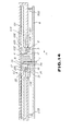
- Fig.18 is a longitudinal cross-sectional view of another modification of the essential parts of the disc table showing the state in which the loading of the disc cartridge on the disc table is started.
- Fig.19 is a longitudinal cross-sectional view showing the state in which the loading of the disc cartridge on the disc table shown in Fig.18 is completed.
- Fig.20 is a plan view showing an embodiment in which a disc table is constituted using a centering member consisting in a spring plate formed of a metallic material
- Fig.21 is a longitudinal cross-sectional view showing a construction of the disc table shown in Fig. 20.
- Fig.22 is an exploded perspective view showing the construction of the disc table shown in Fig.20.
- Fig.23 is a perspective view illustrating the method for producing the disc table showing the process for producing the disc table shown in Fig.20.
- Fig.24 is an enlarged longitudinal sectional view showing the recording disc being loaded on the disc table shown in Fig.20.
- Fig.25 is an enlarged longitudinal sectional view showing the state in which the loading of the recording disc on the disc table shown in Fig.20 is completed.
- Fig.26 is an enlarged longitudinal sectional view showing another modification of a disc table according to the present invention in which the disc member is constituted using a centering member of a spring plate formed of a metallic material.
- the disc table has a table section 2 fitted on a driving shaft 1 of a spindle motor 5 of a disc recording/reproducing apparatus in which the disc table is fitted.
- the table section 2 is formed substantially as a disc from synthetic resin or the like material and has an engaging aperture which is a center aperture engaged by the driving shaft 1.
- An outer peripheral region of an upper surface of the table section 2 is a disc setting surface 3 on which the recording disc 101 as a recording medium is set.
- the function of the supporting section 7 is to increase the length of the engaging aperture 8 so as to be larger than the thickness of the table section 2 for assuring more positive support of the table section 2 by the driving shaft 1.
- the recording disc 101 loaded on the disc table comprises a disc-shaped disc substrate 101a formed of a light-transmitting transparent synthetic resin and a signal recording layer formed on one of the major surfaces of the disc substrate 101a, as shown in Figs.3 and 4.
- the disc substrate 101a has a circular center aperture 102. This circular aperture serves as a reference for the loading position of the disc on the disc table provided within the disc recording/reproducing apparatus.
- annular rib On the opposite major surface of the disc substrate 101a is formed an annular rib surrounding the center aperture 102. On the major surface of the disc substrate carrying the signal recording surface is formed an annular recess 103 surrounding the center aperture 102 in register with the annular rib, as shown in Fig.3.
- a substantially disc-shaped magnetic plate 104 formed of a magnetic material, such as metal, is set within the recess 103. The magnetic plate 104 is retained by the disc substrate 101a by means of an adhesive or supporting lugs formed by thermally deforming part of the disc substrate 101a formed e.g. of synthetic resin.
- the signal recording layer deposited on the firstly-mentioned major surface of the disc substrate 101a, is formed of a metallic material for providing a perpendicular recording magnetic film and a reflective layer for reflecting the light beam, and is used for recording desired information signals.
- the spindle motor 5 is mounted on the lower surface of a chassis 6 of the disc recording/reproducing apparatus, and has its driving shaft 1 extended above the chassis 6 via a through-hole in the chassis 6, as shown in Fig.2.
- an optical pickup device and a magnetic head device are provided for recording and/or reproducing information signals with respect to the signal recording layer of the magneto-optical disc 101 placed on the disc setting surface 3, for movement towards and away from the spindle motor 5, that is in a direction spanning the inner and outer peripheries of the recording disc 101.
- a fitting member 4 is provided at the center of the upper surface of the table section 2.
- the fitting member 4 is substantially conically-shaped and integrated to the table section 2.
- the fitting member 4 is of an outside diameter large enough to be fitted in the center aperture 102 of the recording disc 101.
- the fitting member 4 has its upper end, that is the distal end, as a disc-capturing tapered guide section 4a which is tapered towards its end surface, as shown in Fig.4.
- the outer peripheral surface of the disc-capturing guide section 4a is curved smoothly so as to be merged with the end face of the fitting member 4.
- the fitting member 4 also has its distal side, that is its side proximate to the disc setting surface 3, as a columnar section 4b which is of an outside diameter substantially equal to the inside diameter of the center aperture 102 of the recording disc 101.
- the outer periphery of the fitting member 4 is formed with a groove 25 engaged by a centering ring 11 constituting centering means, as shown in Fig.3.
- the groove 25 has a depth extended from the distal end to a mid part of the fitting member 4 and is in the form of a annulus or toroid coaxial with the fitting member 4.
- the fitting member 4 has an outer peripheral upright wall delimiting the groove 25.
- the peripheral wall has plural cut-outs 10 in communication with the groove 25. These cut-outs 10 are extended radially from the groove 25 towards the outer surface of the fitting member 4. These cut-outs 10 are provided at equiangular intervals about an axis of the fitting member 4 as a center.
- the centering ring 11, fitted into the groove 25 of the fitting member 4, is also formed as a toroid or annulus from metal or synthetic resin exhibiting flexibility and elasticity.
- the centering ring 11 is formed integrally with plural outwardly directed centering segments 12 for centering the recording disc loaded on the disc table.
- These centering segments 12 are tongue-shaped concentric radially extending lugs at equiangular intervals so as to be in register with the cut-outs 10.
- These centering segments 12 are in the form of spring plates so as to be deformed resiliently.
- the centering segments 12 are positioned in such a manner that the proximal ends thereof are in proximity to the end face of the fitting member 4 and-the distal ends thereof are directed with tilt to the disc setting surface 3 and partially projected outwardly of the cut-outs 10, that is towards the outer periphery of the fitting member 4.
- the distal end parts of the centering segments 12 are extended on the periphery of the columnar section 4b in the direction of the disc setting surface 3. That is, the centering segments 12 are extended outwardly of the fitting member 4 at the proximal side of the fitting member 4.
- the distal end parts of these centering segments 12 may be intruded into and protruded out of the cut-outs 10 by the elastic deformation of the proximal parts of the centering segments 12.
- a toroidal-shaped groove 14 enveloping the end parts of the centering segments 12 is formed on the upper surface of the table section 2 in order to allow for elastic deformation of the centering segments 12.
- the end face of the fitting member 4 is formed with a magnet mounting recess 13 which is a circular recess concentric with the fitting member 4.
- a magnet 9 for thrusting and supporting the recording disc 101 with respect to the table section 2 is fitted in the mounting recess 13.
- the magnet 9, in the form of a circular button, is adapted for magnetically attracting a magnetic plate 104 which is mounted at a mid part of the recording disc 101 for closing the center aperture 102.
- the recording disc 101 is fitted by its center aperture 102 over the fitting member 4, as shown in Fig.4. Since the end face section of the fitting member 4 is smoothly merged with its disc capturing taper section 4a, the recording disc 101 is guided towards the mid part of the fitting member 4 so as to be moved towards the distal end of the fitting member 4, with the inner rim of the center aperture 102 being in sliding contact with the outer surface of the disc capturing taper section 4a, under magnetic attraction exerted by the magnet 9 on the magnetic plate 104, even although the disc 101 is offset with respect to the fitting member 4.
- the inner rim of the center aperture 102 is caused to bear on the centering segments 12, as shown in Figs.5 and 6.
- the disc 101 is moved towards the proximal side of the fitting member 4, with its inner rim abutting on and elastically deforming the centering segments 12 for intruding the segments 12 into the cut-outs 10.
- the centering segments 12 thrust the inner rim of the center aperture 102 outwards under their elasticity.
- the disc 101 When the recording disc 101 is fitted on the columnar section 4b of the fitting member 4 by its center aperture 102 and the neighboring portion to the aperture 102 of the disc is set on the disc setting surface 3, the disc 101 is centered by the inner rim of its center aperture 102 thrust by the centering segments 12, with the center of the center aperture 102 being then in register with the axis of the fitting member 4, as shown in Fig.7.
- the magnet 9 then attracts the magnetic plate 104 mounted on the recording disc 101 for pressing the disc 101 against the disc setting surface 3.
- the recording disc 101 When the recording disc 101 is loaded in this manner in position on the table section 2, and the driving shaft 1 is run in rotation by spindle motor 5, the recording disc 101 is rotated in unison with the table section 5.
- the information signals may then be recorded and/or reproduced on or from the signal recording layer of the recording disc 101 by the optical head device or the magnetic head device.
- the centering segment 12 is resiliently biased by an amount a by which the centering segment 12 is protruded beyond the fitting member 4 on a horizontal plane including the disc setting surface 3. It is because the centering segments 12 are resiliently deflected by an amount equal to the amount the segments 12 are protruded from the fitting member 4 on the horizontal plane inclusive of the disc setting surface 3 when the recording disc 101 is set on the disc setting surface 3.
- the centering segments 12, exhibiting the resiliency such that the segments 12 are resiliently protruded by an amount of protrusion from the fitting member 4 on the horizontal plane inclusive of the disc setting surface 3 when the segments are thrust by the thrusting force f equal to about 160 gf, may be formed of a synthetic resin material.
- a disc table is hereinafter explained.
- the centering segments 12 may be integrated with the fitting member 4, as shown in Figs.8 and 9. That is, the fitting member 4 is made up of the fitting member 4 integrated to the centering ring 11 of the preceding disc table.
- a disc table according to an embodiment of the present invention is hereinafter explained.
- a plurality of clamping members 19 are provided as thrusting and supporting means, as shown in Figs.10 to 15.
- the disc table of the present embodiment is designed to hold the recording disc 101 housed for rotation in a cartridge main body to constitute a disc cartridge.
- the recording disc 101 of the present embodiment is not fitted with the magnetic plate 104.
- the disc cartridge is made up of the recording disc 101 and a cartridge main body 104 housing the recording disc 101 therein, as shown in Fig.11.
- the cartridge main body 104 is formed as a substantially rectangular casing for accommodating the recording disc 101 therein. That is, the cartridge main body 104 has a substantially square shape having a side of each of the upper and lower major surfaces extending along the major surfaces of the recording disc 101 slightly longer than the diameter of the recording disc 101.
- the recording disc 101 is accommodated for rotation within the cartridge main body 104.
- a substantially circular chucking aperture 108 is formed in the lower major surface of the cartridge main body 104.
- the chucking aperture 108 is a through-hole slightly larger in diameter than the center aperture 102 of the recording disc 101 and functions to expose the center aperture 102 and its rim portion to outside.
- a recording/reproducing aperture is formed in each of the major surfaces of the cartridge main body 104.
- Each recording/reproducing aperture is provided for extending from the vicinity of the center of one of the major surfaces of the cartridge main body 104 as far as one of the sides of the major surface, that is the vicinity of one of the lateral sides of the cartridge main body 104.
- the function of these recording/ reproducing apertures is to cause the optical pickup device or the magnetic head of the disc recording and/or reproducing apparatus to face the recording disc 101 when recording and/or reading the information signals on or from the signal recording surface of the recording disc 101.
- a pair of annular ribs 106, 107 for controlling the movement along the thickness of the recording disc 101 within the cartridge main body 104 are formed in the vicinity of the rim of the center aperture 102 of the recording disc 101 at opposite positions on the inner wall sections of the cartridge main body 104.
- the disc table of the present embodiment is provided with a table section 2, as is the first and second disc table, as shown in Fig.10.
- the table section 2 has the outer peripheral region of its upper surface as the above-mentioned disc setting surface 3 and has a fitting member 4 protuberantly mounted at the mod part of its upper surface.
- the fitting member 4 has plural centering segments 12.
- the fitting member 4 has plural clamping members 19, 19, 19 each having its mid part supported for rotation. These clamping members 19 are mounted in radially extending clamping member mounting slits 15, 15, 15 provided in the fitting member 4. These clamping members 19 are supported by supporting shafts 17 which are provided in the clamping member mounting slits 15 and which are passed through shaft inserting holes 20 provided at the mid part of the clamping members 19.
- the supporting shafts 17 are formed so that the axial directions thereof extend along the tangent of a circle having the center axis of the table section 2 as a center.
- the clamping member 19 is formed as a substantially T-shaped member having arms extending in two opposite directions from the mid part provided with the shaft inserting hole 20 and a third arm extending in a direction substantially normal to these two arms.
- One of the two arms of the clamping member 19 extending in the two opposite directions functions as the clamping section 23, while the third arm extending in the direction substantially normal to the clamping section 23 functions as a thrust section 22.
- Each of the clamping members 19 in its initial state has the thrust section 22 protruded radially out of the fitting member 4 so as to overlie the disc setting surface 3, while having the clamping section 23 housed within the clamping member mounting slit 15, as shown in Fig.11. Since each of the clamping sections 19 in its initial state is housed within the clamping member mounting slit 15, there is no fear of the clamping member 19 being rotated or destructed by foreign matter or the user's finger inadvertently introduced at the distal end of the fitting member 4.
- clamping member mounting slits 15 are each formed for extending as far as a position of the disc setting surface 3 faced by the thrust sections 22.
- a torsion coil spring 18 for rotationally biasing the clamping member 19 in a direction away from a neutral rotational position of the clamping member 19 is provided in association with each clamping member 19.
- Each of the torsion coil springs 18 resiliently biases a retention pin 21, provided on the other of the two arm sections extended in the two opposite directions, that is the arm section opposite to the clamping section 23 with the shaft inserting opening in-between, in a direction outwardly of the table section 2.
- Each of the torsion coil springs 18 has one of its arm sections engaged with an engaging pin 21 of each of the clamping members 19, while having the other arm section retained by a retention section 24 provided in each of the clamping member mounting slits 15.
- the clamping members 19, 19, 19 are rotationally biased at this time so that the thrust sections 22 thereof are directed to the upper end face of the fitting member 4 in Fig.10, as indicated by arrows D in Figs. 11 and 12.
- the neutral rotational position of the clamping member 19 is the position at which it has been turned from the above-mentioned initial state in a direction of shifting the thrust section 22 towards the disc setting surface 3, and at which the retention section 24, retention pin 21 and the supporting shaft 17 are on a straight line, as shown in Fig.13.
- each of the torsion coil springs 18 biases the associated clamping member 19 in a direction proceeding from the retention pin 21 towards the supporting shaft 17, as shown by arrow E in Fig.13.
- the torsion coil spring 18 rotationally biases the associated clamping member 19 in a direction shown by arrow D in Figs.11 and 12 when the clamping member 19 is at a position rotated in one direction from the neutral position, as shown in Figs.11 and 12.
- the torsion coil spring rotationally biases the clamping member 19 in the opposite direction as indicated by arrow G in Figs.14 and 15.
- the distal end of the fitting member 4 is inserted into the center aperture 102 of the recording disc 101.
- the recording disc 101 has its set section 105 around its center aperture 102 on its opposite major surface abutted against the thrust section 22.
- each clamping member 19 When the recording disc 101 is moved towards the disc setting surface 3, each clamping member 19 has its thrust section 22 thrust by the set section 105 of the recording disc so that the thrust section 22 is rotated in a direction of approaching the disc setting surface 3 against the bias of the torsion coil spring 18, as shown in Fig.13. Each of the clamping members 19 is rotated in this manner to the above-mentioned neutral rotational position.
- each clamping section 19 causes the thrust section 22 to be rotated in a direction of further approaching to the disc setting surface 3, under the bias of the torsion coil spring 18 and under the thrusting force exerted by the set section of the disc on the thrust section 22, as indicated by arrow G in Fig.14.
- the cartridge main body 104 is loaded in position on a chassis 6 by being caused to bear against the distal ends of positioning pins 202, 203 mounted upright on the chassis 6.
- the table section 2 is intruded into the inside of the cartridge main body 104 via chucking aperture 108 provided in the cartridge main body 104.
- each clamping member 19 causes the thrust section 22 to be rotated in a direction of approaching to the disc setting surface 3.
- the clamping members 19 cause the thrust sections 22 to be moved away from the set section 105, while causing the clamp sections 23 to bear against a recess 103 formed in the rim of the center aperture 102 in one of the major surfaces of the recording disc 101.
- the result is that the recording disc 101 is thrust and supported on the disc setting surface 3 by the clamping member 19, as shown in Fig.15.
- the recording disc 101 has its center of rotation coincided with the axis of the disc table by the centering segments 12 of the fitting member 4 by way of performing a centering operation.
- the recording disc 101 is rotated in unison with the table section 2.
- the information signals may be recorded on or reproduced from the signal recording layer by the optical pickup device or the magnetic head device.
- Each of the clamping members 19 has its clamping section 23 thrust upwards by the recording disc 101 so as to be rotated beyond the above-mentioned neutral rotational position so as to be returned to its initial position.
- the recording disc 101 housed within the cartridge main body 104 may be set with correct centering on the disc setting surface 3, as hereinabove described.
- the number of the clamping members may be at least two or four or more in stead of three in the above described disc table.
- a disc table is hereinafter explained.
- the centering segments 12 may be mounted in a stressed state, that is in a state of being resiliently flexed inwardly towards the center axis of the fitting member 4, as shown in Fig.16, instead of in a natural or stress-free state, that is in a state free from resilient flexing.
- the centering segments 12 have their distal ends intruded into the cut-outs 10 in the inwardly resiliently flexed or stressed state so that the distal ends are caused to bear against the inner wall sections of the cut-outs 10. That is, with the present disc table, the inner wall sections of the cut-outs 10 act as resetting controlling sections for controlling the resetting of the centering segments 12 to their natural state.
- each of the centering segments 12 has its distal end resiliently biased from the position of being caused to bear against the inner wall section of the cut-out 10 to the position of being caused to bear against the inner rim of the center aperture 102 of the recording disc 101, as shown by arrow J in Fig. 17.
- centering segments 12 are not biased from their unstressed state, it is possible for these centering segments 12 to exhibit a sufficient thrusting force corresponding to the displacement from the unstressed state, which thrusting force may be exerted on the inner rim of the center aperture 102 of the recording disc 101, even although the segments 12 deemed as spring plates are of a small spring constant. Consequently, the recording disc 101 may be correctly centered by these centering segments 12. Besides, in the initial state in which the recording disc 101 is not loaded, the centering segments 12 are controlled in their positions by the inner wall sections of the cut-outs 10 and hence positioned with great accuracy.
- a disc table is hereinafter explained.
- the centering means in this disc table is not limited to plural centering segments in the form of plural spring plates, as those shown in the above-described embodiments, but may consist in plural centering segments 12 connected to an annular section of the centering ring 11 via hinges 12a, and an elastic member 12b, as shown in Fig. 18.
- the centering segments 12 are pawl-shaped lugs disposed at equiangular intervals in register with the cut-outs 10 for extending radially relative to the annular section of the centering ring 11. These centering segments are intruded into the cut-outs 10.
- each of the centering segments of the present disc table has only its distal end projected out of the fitting member 4 at the proximal part of the fitting member 4.
- Each hinge 12a is formed at the proximal side of each centering segment 12 by locally reducing the thickness of the centering segment 12.
- the centering segments 12 may be biased in a direction of being protruded out of or being receded inwardly of the fitting member 4 by resilient flexure of the hinge 12a.
- the elastic member 12b is formed substantially as an annulus from an elastic material, such as butyl rubber, and is interposed between the centering segments 12 and the annular section of the centering ring 11. That is, the elastic member 12b is fitted to the outer side of the annular section of the centering ring 11 and is disposed inwardly of the centering segments 12.
- the centering segments 12 are displaced by being thrust by the inner rim of the centering aperture 102 to thrust the elastic member 12b, as shown by arrow K in Fig. 19, with the inner rim of the center aperture 102 in turn being thrust by the elastic recoiling of the elastic member 12b.
- the centering segments 12 are not susceptible to creeping even after repeated displacement and hence exhibit excellent durability. Since the thrusting force against the inner rim of the center aperture 102 of the recording disc 101 is obtained by the force of elastic recoiling of the elastic member 12b, the thrusting force may be increased to a sufficient level by suitably selecting the material and/or the shape of the elastic member 12b. Consequently, the recording disc 101 may be satisfactorily centered by the centering segments 12.
- a disc table and the method for producing the disc table according to the present invention are hereinafter explained.
- the disc table may be constituted using a centering ring 11 formed of a metallic spring plate material, as shown in Figs.20 to 22, 24 and 25.
- the present disc table is also provided with a table section 2 supported by being fitted on the outer surface of the driving shaft 1 of the spindle motor 5.
- the table section 2 is formed substantially as a disc from a synthetic resin and has a center through-hole 8 engaged by the driving shaft 1.
- the table section 2 has a perimetral portion of its upper surface as a disc setting surface 3 for setting the recording disc 101 thereon.
- the spindle motor 5 for rotationally driving the disc table is mainly made up of an outer casing 35, a bearing 34 supported by the outer casing 35 for rotatably supporting the driving shaft, annular magnets 32, 32 mounted on the driving shaft 1 via a magnet supporting member 33 and a coil base plate mounted facing the magnets 32, 32 within the outer casing 35.
- the spindle motor 5 is supported by having the outer casing 35 mounted on the lower surface of the chassis 6 so that the driving shaft 1 is protruded above the chassis 6 via a through-hole bored in the chassis 6.
- a fitting member 4 is projectedly formed at the center of the upper surface of the table section 2, as in the preceding disc tables. That is, the fitting member 4 is formed with the table section 2 in substantially a conical shape and has an outside diameter large enough to be engaged in the center aperture 102 of the recording disc 101.
- the distal part of the fitting member 4 is a guide section for capturing the recording disc 101.
- the part of the fitting member 4 lying close to the disc setting surface 3 is a columnar section 4b having an outside diameter substantially equal to the inside diameter of the center aperture 102 of the recording disc 101.
- the distal end face of the fitting member 4 has a magnet mounting recess 13 which is formed as an annular groove concentric with the fitting member 4. Within this magnet mounting recess 13 is mounted an annular magnet 9 acting as thrusting and supporting means.
- the magnet 9 is used for attracting a magnetic plate 104 mounted at the mid part of the recording disc 101 for closing the center aperture 102, as shown in Figs.24 and 25.
- a magnetic yoke formed of a high permeability material may be provided on the lower surface of the magnet 9, that is between the magnet 9 and the fitting member 4.
- the fitting member 4 has plural cut-outs 10 in communication with the magnet mounting recess 13. These cut-outs 10 are formed outwardly of the magnet mounting recess 13 for extending radially from the magnet mounting recess 13 through the proximal side of the fitting member 4 as far as a disc-shaped part of the table section 2. These cut-outs 10 are provided at three points at an angular interval of 120° relative to each other.
- the centering ring 11 is formed as one from a plate-shaped metallic spring material by punching and press working.
- the centering ring 11 comprises a substantially disc-shaped base section 26, three upstanding supporting projections 29 provided on the perimetral portions of the base section 26 and three centering segments 12 extending outwardly from the distal ends of these supporting projections 29, as shown in Fig.22.
- the base section 26 has a central through-hole 27 having a diameter sufficiently larger than the outside diameter of the driving shaft 1.
- the supporting projections 29, 29, 29 are formed upright around the perimeter of the base section 26 at an equiangular interval of 120° relative to one another. These supporting projections 29 are formed by bending three tongues extending outwardly from the outer perimeter of the base section 26 by press working. These supporting projections 29 are formed with drawn parts 30, 30, 30 extending outwards from the base section 26. These drawn parts are formed by drawing so that part of the spring material of the centering ring 11 is bent to form rib-shaped projections extending from the supporting projections 29 and the base section 26. These drawn parts 30 prevent the supporting projections 29 from being tilted with respect to the base section 26.
- the proximal ends of the centering segments 12 are formed as continuation of the distal ends of the supporting projections 29. These centering segments 12 are positioned outwardly of the supporting projections 29, that is at a distance from the base section 26, and are inclined downwardly from the distal ends of the supporting projections 29.
- the distal end of each of the centering segments 12 is formed with a pair of bent tabs 31 ,31. These tabs 31, 31 are formed as tongues on the opposite lateral sides of the centering segments 12 and arcuately bent towards the center of the base section 26.
- These centering segments 12 and the tabs 31, 31 of each of these segments are formed by press-working the parts extended horizontally from the supporting projections 29.
- the perimetral part of the base section 26 is formed with three equiangular cut-outs 28 for accommodating an adhesive which are disposed between the supporting projections 29. These cut-outs 28 are substantially semicircular in contour.
- the centering segments 12 are intruded into the cut-outs 10 by the base section 26 being mounted on the lower surface of the table section 2.
- the base section 26 is mounted on the table section 2 by applying an adhesive, such as a so-called UV curable resin, in the cut-outs 28 for adhesive, while the major surface of the base section 26 is kept in pressure contact with the lower surface of the table section 2.
- the distal ends of the supporting projections 29 are positioned at this time around the perimeter of the magnet 9 and are spaced apart from the magnet 9 and the fitting member 4. These centering segments 12 may be biased resiliently.
- each of the centering segments 12 has its proximal end positioned in the vicinity of the distal end face of the fitting member 4, and is supported with a tilt relative to the disc setting surface 3, so that part of the distal end thereof is projected outwardly from the cut-out 10, that is in the direction of the perimeter of the fitting member 4, as shown in Fig.24.
- the distal end of each of these centering segments 12 may be projected beyond or receded with respect to the peripheral surface of the fitting member 4 by elastic deformation of the proximal part of each of the segments 12.
- the distal end of each of these segments 12 is disposed below the disc setting surface 3 so as to be caused to bear against the inner wall of the cut-out 10.
- the centering segments 12 are resiliently biased at this time closer to the base section 26 than when the segments 12 are in the stress-free state.
- the method for producing the disc table having the centering ring 11 formed of the spring plate material is hereinafter explained in detail.
- a positioning jig 50 shown in Fig.23 is employed.
- the positioning jig 50 has a block-shaped main body having a recessed positioning hole 51.
- a reference shaft 53 having a outside diameter substantially equal to that of the driving shaft 1 of the spindle motor 5 is mounted upright on the bottom surface of the positioning hole 51.
- Part of the inner wall of the positioning hole 51 is formed as wall sections 52, 52, 52 for abutment with the centering segments 12 in register with the cut-outs 10, 10, 10.
- the portions of the inner wall other than the wall sections 52, 52, 52 are enlarged in diameter radially outwardly of the wall sections 52, 52, 52.
- These wall sections 52, 52, 52 are designed to form a part of a cylindrical surface coaxial with the reference shaft 53.
- the diameter of the cylindrical surface enveloping the wall sections 52 is selected to be slightly smaller than the inside diameter of the center aperture 102 of the recording disc 101, and is typically on an order of 10.98 to 10.99 mm for the inside diameter of the center aperture 102.
- the reference shaft 52 is fitted into the fitting thorough-hole 8 for the table section 2 bored in the fitting member 8, as shown in Fig.23.
- the reference shaft 53 is engaged in the fitting through-hole 8, as the fitting member 4 is faced by the positioning hole 51 so that the fitting member 4 may be fitted into the positioning hole 51.
- the cut-outs 10 are in register with the wall sections 52.
- the centering ring 11 is then set on the table section 2 loaded on the positioning jig 50.
- the centering ring 11 has its base section 26 set on the lower surface of the table section 2 so that the centering segments 12 are introduced into the cut-outs 10.
- Each of the centering segments 12 has its distal end abutted against the wall sections 52. Since the centering segments 12 are resiliently biased towards the base section 26, the centering segments 12 thrust the wall sections 52 by their resiliency.
- the centering ring 11 is moved to and halted at a position at which the resilient recoiling forces of the centering segments 12 are in equilibrium, that is a position at which the resilient recoiling forces of the centering segments 12 become equal to one an another.
- the supporting projections 29, the magnet 9 and the fitting member 4 are spaced apart from one another, there is no risk of obstruction of the movement of centering ring 11 under the resilient recoiling force of the centering segments 12.
- the centering ring 11 is fixedly mounted on the fitting member 4 by being bonded to the lower surface of the table section 2 by UV resin or thermoplastic adhesive 32 at the position at which the resilient recoiling forces of the centering segments 12 counterbalance one another.
- the adhesive in a fluid state is dripped into the cut-outs 28 so that the adhesive 32 is in contact with both the centering ring 11 and the table section 2, the adhesive 12 being then allowed to be cured in situ.
- the adhesive 32 is cured by irradiation of UV rays by heating.
- the table section 2 is then dismounted from the positioning jig 50 along with the centering ring 11.
- the centering segments 12 of the centering ring 11, thus mounted on the table section 2 are designed to produce outwardly directed resilient recoiling forces of equal magnitude when the segments are deflected as far as a circumference of a circle coaxial as the fitting hole 8 and having a diameter substantially equal to the diameter of the recording disc 101.
- the recording disc 101 is fitted on the fitting member 4 so that the rim of the center aperture 102 of the disc 101 is engaged with the fitting member 4, as shown by arrow C in Fig.24.
- each of the centering segments 12 is resiliently biased from the position at which it has its distal end abutted against the inner rim of the cut-out 10 to a position at which the centering segment has its distal end abutted against the center aperture 102 of the recording disc 101, as shown by arrow J in Fig.25.
- the inner rim of the center aperture 102 is thrust outwards under the resilient restoring force of the centering segments 12.
- the magnet 9 attracts the magnetic plate 104 mounted on the recording disc 101 for thrusting and supporting the recording disc 101 with respect to the disc setting surface 3.
- the recording disc 101 When the recording disc 101 is loaded in position on the table section 2, and the driving shaft 1 is run in rotation by the spindle motor 5, the recording disc 101 is rotated in unison with the table section 2.
- the information signals are recorded on or reproduced from the signal recording layer of the recording disc 101 by the optical head device or the magnetic head device.
- the spring constant k 0 of the centering segments 12 is selected to be not less than the minimum value k 1 of the spring constant capable of sufficiently correcting an offset of the recording disc 101 with respect to the fitting member 4 and not larger than the maximum value K of the spring constant capable of shifting the recording disc 101 to the position of abutting the recording disc 101 against the disc setting surface 3 under the force of magnetic attraction by the magnet 9 of the magnetic plate 104.
- the spring constant of the centering segments 12 is k
- the displacement of the centering segments 12 is ⁇
- the frictional coefficient between the centering segments 12 and the inner rim of the recording disc 101 is ⁇ 1
- the frictional coefficient between the recording disc 101 and the disc setting surface 3 is ⁇ 2 .
- the spring constant of the centering segments 12 set in this manner may be substantially five times as large as the spring constant when the centering segments 12 are formed of a spring plate material of synthetic resin of the same thickness as that of the metallic spring plate material.
- the recording disc 101 may be centered satisfactorily by the centering segments 12. Besides, since the distal ends of the centering segments 12 are caused to bear against the inner wall sections of the cut-outs 10, the thrusting force exerted on the inner rim of the center aperture 102 undergoes less fluctuations by an error possibly present in the spring constants. In addition, in the initial state in which the recording disc 101 is not loaded in position, the centering segments 12 are controlled in their positions by the inner wall sections of the cut-outs 10, so that the centering segments 12 may be positioned with great accuracy.
- centering segments 12 are formed of a metallic material, they are excellent in creep resistance and exhibit superior durability under high temperature environment. Furthermore, these centering segments 12 may be fabricated with a precise spring constant as compared to the case wherein the segments 12 are fabricated from a synthetic resin.
- Each centering segment 12 is provided with the tabs 31, 31, and has the portion abutted against the inner rim of the center aperture 102 of the recording disc 101 bent substantially arcuately towards the base section 26, so that it becomes possible to prevent a damage from being done to the inner rim of the center aperture 102 as well as to assure smooth movement of the recording disc 101 towards the disc setting surface 3.
- the distal ends of the centering segments 12 may be provided with pads 34 of synthetic material, as shown in Fig.26, instead of with the bent tabs 31, 31.
- These pads 34 may be provided on the centering segments 12 by a so-called outsert molding method. These pads 34 are provided at the portions of the centering segments 12 abutted against the inner rim of the centering aperture 102, so that, in the initial state in which the recording disc 101 is not loaded in position, the pads 34 are projected outwardly of the fitting member 4.
Landscapes
- Holding Or Fastening Of Disk On Rotational Shaft (AREA)
Claims (15)
- Table de support de disque sur lequel un disque (101) est posé et qui est entraíné en rotation en même temps que ledit disque, comprenant :caractérisée en ce que :un élément d'ajustement (4) ajusté, au niveau de son extrémité distale, dans une ouverture centrale circulaire (102) ménagée dans ledit disque,une section table (2) se trouvant à une extrémité proximale dudit élément d'ajustement et ayant une surface de pose (3) sur laquelle une partie périmétrique de ladite ouverture centrale dudit disque est posée,un moyen de serrage (19) servant à serrer ledit disque sur ladite section table, etun moyen de centrage (11) disposé au niveau d'un côté proximal dudit élément d'ajustement et poussant le bord interne de l'ouverture centrale du disque afin d'aligner le centre dudit disque avec le centre dudit élément d'ajustement, etoù ladite section table (2) est incorporée avec ledit élément d'ajustement ;ledit moyen de centrage (11) comprend plusieurs éléments de centrage (12) se présentant sous la forme de lames de ressort disposées dans ledit élément d'ajustement (4) de façon à sortir de la surface périphérique externe de l'extrémité distale dudit élément d'ajustement et à reculer vers l'intérieur de cette surface, lesdits éléments de centrage étant en appui contre le bord interne (103) de l'ouverture centrale (102) du disque (101), etledit moyen de serrage comprend plusieurs élément de serrage (19) ajustés radialement sur ledit élément d'ajustement (4) et soutenus en rotation pour pouvoir chacun tourner sur un axe tangent à la direction circonférentielle de ladite section table (2).
- Table de support de disque selon la revendication 1, où ledit élément d'ajustement (14) présente un diamètre réduit de façon à avoir une partie s'amincissant de capteur de disque au niveau de son extrémité distale lui permettant de venir en contact glissant avec le bord interne de l'ouverture centrale (102) du disque (101) afin de guider le disque en direction du côté du centre.
- Table de support de disque selon la revendication 1 ou 2, où l'extrémité proximale dudit élément d'ajustement (4) possède un diamètre extérieur sensiblement égal au diamètre de l'ouverture centrale (102) du disque (101).
- Table de support de disque selon l'une quelconque des revendications 1 à 3, où ladite section table (2) est dotée d'une section de commande (10) servant à maintenir l'état sollicité vers l'intérieur élastiquement dudit élément d'ajustement (4) et à commander le retour élastique desdits éléments de centrage (12) à leur état naturel, dans lequel les éléments de centrage font saillie à l'extérieur de l'élément d'ajustement.
- Table de support de disque selon l'une quelconque des revendications 1 à 4, où lesdits éléments de centrage (12) sont formés en un matériau pour lame de ressort métallique.
- Table de support de disque selon l'une quelconque des revendications 1 à 5, où ledit élément de centrage (12) est formé solidairement avec ledit élément d'ajustement (4 ; 14) fait en une résine synthétique.
- Table de support de disque selon l'une quelconque des revendications 1 à 6, où chaque élément de serrage (19) est, dans sa partie médiane, soutenu de manière rotative par ledit élément d'ajustement (4) et possède des premier et deuxième bras (22, 23) s'étendant dans deux sens opposés depuis ladite partie médiane, ledit premier bras (22) ayant une section de poussée qui est poussée par la partie périmétrique de l'ouverture centrale (102) du disque d'enregistrement (101) lorsque le disque d'enregistrement approche la surface de pose de disque de ladite section de table (2), ledit deuxième bras (23) comportant une section de serrage qui sert à pousser et soutenir ledit disque sur ladite surface de pose par le fait qu'il tourne à l'unisson avec ladite section de poussée lorsque ladite section de poussée est poussée.
- Table de support de disque selon l'une quelconque des revendications 1 à 7, où ledit moyen de serrage (22, 23) comprend en outre un ressort hélicoïdal de torsion (18) associé à chaque élément de ressort afin de solliciter élastiquement ledit élément de serrage (19) suivant deux directions, pouvant commuter, qui sont la direction de rapprochement de ladite section de poussée (22) vis-à-vis de la surface de pose de ladite section de table (2) et la direction d'écartement de ladite section de poussée par rapport à ladite surface de pose, une position neutre de rotation dudit élément de serrage (19) constituant un point de base.
- Table de support de disque selon l'une quelconque des revendications 1 à 8, où ledit moyen de centrage comprend une bague de centrage (11) ajustée et soutenue par ledit élément d'ajustement (4), plusieurs segments de centrage (12) qui sont radialement raccordés à ladite bague de centrage via une section de charnière (12a), et un élément élastique (12b) servant à amener lesdits segments de centrage à faire saillie de la surface périphérique externe du côté proximal dudit élément d'ajustement ou à reculer vers l'intérieur de cette surface.
- Table de support de disque selon la revendication 9, où ledit élément élastique (12b) se présente sous la forme d'un élément annulaire fait en un matériau élastique et s'interposant entre lesdits segments de centrage (12) et ladite bague de centrage (11).
- Table de support de disque selon l'une quelconque des revendications 1 à 10, où ledit moyen de centrage (11) se présente sous la forme d'un élément élastique en forme de plaque fait en un matériau métallique, chacun desdits segments de centrage (12) ayant un côté proximal incorporé à ladite section de base et ayant une extrémité distale qui fait saillie de la périphérie externe du côté proximal dudit élément d'ajustement de façon à être en appui contre le bord interne de l'ouverture centrale (102) dudit disque et, ainsi, être élastiquement sollicité en direction de ladite section de base.
- Table de support de disque selon la revendication 11, où ladite section table (2) possède une section de commande (110) destinée à venir en appui contre l'extrémité distale de chaque segment de centrage dans un état de flexion élastique en direction de ladite section de base afin de commander le retour élastique dudit segment de centrage à son état non contraint naturel.
- Table de support de disque selon l'une quelconque des revendications 11 et 12, où ledit moyen de centrage comporte plusieurs parties saillantes de soutien (12) ayant chacune leur extrémité proximale qui est solidairement formée avec une partie périmétrique de ladite section de base et pendant de cette partie périmétrique et ayant son extrémité distale raccordée à l'extrémité proximale de chacun desdits segments de centrage, chaque dite partie saillante de soutien ayant une partie étirée qui s'en prolonge jusqu'aussi loin que ladite section de base.
- Table de support de disque selon l'une quelconque des revendications 11 à 13, où ledit moyen de centrage (12) comporte une paire de pattes fléchies de manière courbe depuis l'extrémité distale de chacun desdits segments de centrage jusqu'à une partie médiane de ladite section de base.
- Table de support de disque selon l'une quelconque des revendications 11 à 14, où ledit moyen de centrage (11) comporte des patins fixés aux extrémités distales desdits segments de centrage.
Priority Applications (1)
| Application Number | Priority Date | Filing Date | Title |
|---|---|---|---|
| EP01200276A EP1094462B1 (fr) | 1992-01-24 | 1993-01-22 | Méthode de fabrication de table de support de disque pour appareil d' enregistrement/lecture de disque |
Applications Claiming Priority (9)
| Application Number | Priority Date | Filing Date | Title |
|---|---|---|---|
| JP3293292 | 1992-01-24 | ||
| JP3293292 | 1992-01-24 | ||
| JP32932/92 | 1992-01-24 | ||
| JP157300/92 | 1992-05-26 | ||
| JP15730092 | 1992-05-26 | ||
| JP15730092 | 1992-05-26 | ||
| JP28521892 | 1992-09-30 | ||
| JP285218/92 | 1992-09-30 | ||
| JP28521892A JP3384002B2 (ja) | 1992-01-24 | 1992-09-30 | ディスクテーブル及び記録及び/又は再生装置 |
Related Child Applications (1)
| Application Number | Title | Priority Date | Filing Date |
|---|---|---|---|
| EP01200276A Division EP1094462B1 (fr) | 1992-01-24 | 1993-01-22 | Méthode de fabrication de table de support de disque pour appareil d' enregistrement/lecture de disque |
Publications (3)
| Publication Number | Publication Date |
|---|---|
| EP0553034A2 EP0553034A2 (fr) | 1993-07-28 |
| EP0553034A3 EP0553034A3 (fr) | 1995-07-12 |
| EP0553034B1 true EP0553034B1 (fr) | 2001-09-26 |
Family
ID=27287904
Family Applications (2)
| Application Number | Title | Priority Date | Filing Date |
|---|---|---|---|
| EP93400159A Expired - Lifetime EP0553034B1 (fr) | 1992-01-24 | 1993-01-22 | Table support de disque pour appareil d' enregistrement/lecture de disque |
| EP01200276A Expired - Lifetime EP1094462B1 (fr) | 1992-01-24 | 1993-01-22 | Méthode de fabrication de table de support de disque pour appareil d' enregistrement/lecture de disque |
Family Applications After (1)
| Application Number | Title | Priority Date | Filing Date |
|---|---|---|---|
| EP01200276A Expired - Lifetime EP1094462B1 (fr) | 1992-01-24 | 1993-01-22 | Méthode de fabrication de table de support de disque pour appareil d' enregistrement/lecture de disque |
Country Status (5)
| Country | Link |
|---|---|
| US (4) | US5501760A (fr) |
| EP (2) | EP0553034B1 (fr) |
| JP (1) | JP3384002B2 (fr) |
| KR (1) | KR100248479B1 (fr) |
| DE (2) | DE69330806T2 (fr) |
Families Citing this family (73)
| Publication number | Priority date | Publication date | Assignee | Title |
|---|---|---|---|---|
| JP3384002B2 (ja) * | 1992-01-24 | 2003-03-10 | ソニー株式会社 | ディスクテーブル及び記録及び/又は再生装置 |
| US6038206A (en) * | 1991-02-07 | 2000-03-14 | Sony Corporation | Disc table for disc recording/reproducing apparatus and method for producing same |
| US5774445A (en) * | 1993-08-09 | 1998-06-30 | Funai Electric Co., Ltd. | Disc clamp mechanism having radial disposed disc pressing elements |
| KR950020570A (ko) * | 1993-12-24 | 1995-07-24 | 배순훈 | 미니디스크겸용 콤팩트디스크 턴테이블 |
| JPH08106693A (ja) * | 1994-10-04 | 1996-04-23 | Toshiba Corp | ディスク再生装置 |
| US5486962A (en) | 1994-10-12 | 1996-01-23 | International Business Machines Corporation | Integral hub and disk clamp for a disk drive storage device |
| JPH08195010A (ja) * | 1995-01-13 | 1996-07-30 | Matsushita Electric Ind Co Ltd | ディスクセンタリング装置 |
| US5664314A (en) * | 1995-05-08 | 1997-09-09 | Seagate Technology, Inc. | Method of making a spindle motor to allow magnetic alignment between the magnet and the stator in the motor |
| EP0747897A3 (fr) * | 1995-06-06 | 1997-08-06 | Iomega Corp | Mécanisme de verrouillage de moyen de cassette à disque |
| GB9604048D0 (en) * | 1996-02-26 | 1996-04-24 | Grossman Stanley I | Labelling device and label |
| CN1306509C (zh) * | 1996-04-19 | 2007-03-21 | 松下电器产业株式会社 | 叠层式光盘制造方法及其装置 |
| JPH09320159A (ja) * | 1996-05-27 | 1997-12-12 | Mitsubishi Electric Corp | 貼り合せディスクのターンテーブル装置および貼り合せディスク |
| KR100417231B1 (ko) * | 1996-05-29 | 2004-04-21 | 삼성전자주식회사 | 디스크클램핑방법 |
| JPH10106134A (ja) * | 1996-09-20 | 1998-04-24 | Sony Corp | ディスク駆動装置 |
| JPH10112099A (ja) * | 1996-10-02 | 1998-04-28 | Alps Electric Co Ltd | ディスク駆動装置 |
| TW358198B (en) * | 1996-12-18 | 1999-05-11 | Matsushita Electric Ind Co Ltd | Dish holding device |
| JP3008870B2 (ja) * | 1996-12-27 | 2000-02-14 | 日本電気株式会社 | ディスク媒体用ターンテーブル装置 |
| JPH1173721A (ja) * | 1997-08-22 | 1999-03-16 | Samsung Electro Mech Co Ltd | ディスクドライブ用ブラシレスdcモータ |
| KR100425340B1 (ko) * | 1997-08-30 | 2004-05-17 | 삼성전자주식회사 | 디스크 클램핑 장치 |
| US5958177A (en) * | 1997-09-16 | 1999-09-28 | Claussnitzer; Werner | Labelling device |
| US6128151A (en) * | 1997-10-29 | 2000-10-03 | Iomega Corporation | Method and a system for engaging a disk drive spindle motor with a disk cartridge |
| US6130801A (en) * | 1997-11-07 | 2000-10-10 | Seagate Technology, Inc. | Composite disc spacer for a disc drive |
| KR100269154B1 (ko) * | 1998-02-17 | 2000-10-16 | 윤종용 | 디스크플레이어의턴테이블조립체 |
| CN1229242A (zh) * | 1998-03-18 | 1999-09-22 | 株式会社三协精机制作所 | 记录盘夹紧机构 |
| JPH11296942A (ja) * | 1998-04-09 | 1999-10-29 | Sony Corp | ディスクのチャック装置 |
| EP0957480A1 (fr) | 1998-05-15 | 1999-11-17 | Deutsche Thomson-Brandt Gmbh | Unité de disque avec compensation de l'excentricité d'un disque |
| EP0957481B1 (fr) * | 1998-05-15 | 2006-09-27 | Deutsche Thomson-Brandt Gmbh | Lecteur de disque compensant l'excentricité des disques |
| JP3502266B2 (ja) * | 1998-06-18 | 2004-03-02 | 日本電産株式会社 | 記録媒体の駆動用モータ |
| US6084236A (en) * | 1998-07-23 | 2000-07-04 | Sony Corporation | System for mounting a hubless glassmaster onto an orders measurement device |
| DE19859356A1 (de) * | 1998-12-22 | 2000-06-29 | Thomson Brandt Gmbh | Aufzeichnungs- oder Wiedergabegerät mit einer Halterung für plattenförmige Aufzeichnungsträger |
| DE19859357A1 (de) * | 1998-12-22 | 2000-06-29 | Thomson Brandt Gmbh | Aufzeichnungs-oder Wiedergabegerät mit einer Auf- und Abnahmevorrichtung für plattenförmige Aufzeichnungsträger |
| TW420347U (en) * | 1999-01-11 | 2001-01-21 | Sunonwealth Electr Mach Ind Co | Transfer system structure of main axis motor for CD-ROM drive |
| JP2000285557A (ja) * | 1999-03-31 | 2000-10-13 | Sony Corp | ディスクドライブ装置及びそのターンテーブル |
| JP2000311409A (ja) * | 1999-04-23 | 2000-11-07 | Sony Computer Entertainment Inc | 光ディスク装置 |
| JP2001176183A (ja) * | 1999-12-10 | 2001-06-29 | Sony Corp | ディスクセンターリング装置 |
| JP2001266473A (ja) * | 2000-03-23 | 2001-09-28 | Tokyo Parts Ind Co Ltd | ディスク載置部を備えたスピンドルモータ |
| US6829777B2 (en) * | 2000-04-17 | 2004-12-07 | Sony Corporation | Turn table and optical disk using the turn table |
| US6776291B1 (en) * | 2000-09-27 | 2004-08-17 | Xerox Corporation | Article and apparatus for particulate size separation |
| CN100362585C (zh) * | 2001-04-12 | 2008-01-16 | 松下电器产业株式会社 | 圆盘状信息记录介质用转台和圆盘装置 |
| WO2002089132A1 (fr) * | 2001-04-26 | 2002-11-07 | Koninklijke Philips Electronics N.V. | Table de lecture pour un support d'informations en forme de disque, et lecteur avec table de lecture de ce type |
| US7484231B2 (en) * | 2001-05-14 | 2009-01-27 | Lg Electronics Inc. | High-density disk recording medium having an asymmetrically-shaped center hole and manufacturing method thereof |
| JP3813485B2 (ja) * | 2001-10-16 | 2006-08-23 | 三洋電機株式会社 | 回転テーブル装置 |
| JP2003303460A (ja) * | 2002-04-08 | 2003-10-24 | Minebea Co Ltd | スピンドルモータ |
| SE524466E (sv) * | 2002-12-12 | 2007-09-04 | Metso Paper Inc | Anordning för blandning av ett gas- eller vätskeformigt kemikaliemedium med en massasuspension |
| JP2004234773A (ja) * | 2003-01-31 | 2004-08-19 | Tokyo Parts Ind Co Ltd | ターンテーブル |
| TWI222262B (en) * | 2003-07-24 | 2004-10-11 | Delta Electronics Inc | Spindle motor centering device |
| JP3849874B2 (ja) * | 2003-10-08 | 2006-11-22 | ソニー株式会社 | ディスク記録媒体のチャッキング機構及び該機構を用いたディスクドライブ装置 |
| JP4278618B2 (ja) * | 2004-03-04 | 2009-06-17 | 富士通テン株式会社 | ディスク状記録媒体のクランプ機構 |
| US7441257B2 (en) * | 2004-03-10 | 2008-10-21 | Delphi Technologies, Inc. | Method and apparatus for cooling a compact disc |
| EP1738360B1 (fr) * | 2004-03-26 | 2008-02-20 | Koninklijke Philips Electronics N.V. | Appareil de centrage d'un support d'information sur un plateau |
| JP2006252606A (ja) * | 2005-03-08 | 2006-09-21 | Mitsubishi Electric Corp | ディスククランプ装置 |
| JP2006252711A (ja) * | 2005-03-11 | 2006-09-21 | Nippon Densan Corp | 薄型ブラシレスモータ |
| JP2007066429A (ja) * | 2005-08-31 | 2007-03-15 | Orion Denki Kk | 記録/再生装置のクランパ及び該クランパを備えた記録/再生装置 |
| US20070201164A1 (en) * | 2005-11-28 | 2007-08-30 | Bauck Randall C | Data storage device with hard drive and interchangeable data storage disks |
| JP2007310920A (ja) * | 2006-05-16 | 2007-11-29 | Seiko Epson Corp | ディスクのグリッピング機構 |
| JP4946208B2 (ja) * | 2006-06-29 | 2012-06-06 | 日本電産株式会社 | 記録媒体の保持装置とそれを用いたモータユニット |
| US20080170325A1 (en) * | 2007-01-11 | 2008-07-17 | Laserresearch (S) Pte Ltd | Disk Centering Assembly And Spindle Hub |
| JP4493670B2 (ja) * | 2007-02-20 | 2010-06-30 | 三洋電機株式会社 | ディスク駆動装置 |
| JP5092476B2 (ja) * | 2007-03-19 | 2012-12-05 | 日本電産株式会社 | チャッキング装置を備えたモータ、およびこのモータを搭載したディスク駆動装置 |
| JP4992497B2 (ja) * | 2007-03-19 | 2012-08-08 | 日本電産株式会社 | チャッキング装置を備えたモータ、およびこのモータを搭載したディスク駆動装置 |
| JP4978257B2 (ja) * | 2007-03-19 | 2012-07-18 | 日本電産株式会社 | チャッキング装置を備えたモータ、およびこのモータを搭載したディスク駆動装置 |
| JP5076573B2 (ja) * | 2007-03-19 | 2012-11-21 | 日本電産株式会社 | チャッキング装置を備えたモータ、およびこのモータを搭載したディスク駆動装置 |
| KR100918853B1 (ko) * | 2007-11-12 | 2009-09-28 | 삼성전기주식회사 | 턴테이블 장치 및 이를 구비한 디스크 구동 장치 |
| KR101020792B1 (ko) | 2008-09-29 | 2011-03-09 | 엘지이노텍 주식회사 | 스핀들 모터의 턴 테이블 |
| US8196622B1 (en) * | 2008-11-20 | 2012-06-12 | Fisher Michael A | Apparatus for receiving and dispensing granulated materials |
| KR101020800B1 (ko) * | 2008-12-29 | 2011-03-09 | 엘지이노텍 주식회사 | 스핀들 모터 |
| KR101062023B1 (ko) * | 2009-08-06 | 2011-09-05 | 삼성전기주식회사 | 모터 |
| KR101091345B1 (ko) * | 2009-08-18 | 2011-12-07 | 엘지이노텍 주식회사 | 척 부재를 포함한 스핀들 모터 |
| KR101071033B1 (ko) | 2009-08-25 | 2011-10-06 | 엘지이노텍 주식회사 | 스핀들 모터 |
| KR101077297B1 (ko) * | 2009-11-30 | 2011-10-26 | 삼성전기주식회사 | 디스크 척킹장치 |
| US8467146B2 (en) * | 2010-08-30 | 2013-06-18 | Samsung Electro-Mechanics Co., Ltd. | Apparatus for clamping disk and motor assembly having the same |
| CN104036792A (zh) * | 2013-03-08 | 2014-09-10 | 光宝科技股份有限公司 | 夹持装置 |
| JP6003765B2 (ja) * | 2013-03-28 | 2016-10-05 | トヨタ自動車株式会社 | 高圧ガスタンクの製造方法とプロテクター装着治具 |
Citations (2)
| Publication number | Priority date | Publication date | Assignee | Title |
|---|---|---|---|---|
| EP0192188A2 (fr) * | 1985-02-16 | 1986-08-27 | Hitachi Maxell Ltd. | Disposition pour le positionnement d'un disque d'enregistrement placé dans une cassette |
| JPS63136353A (ja) * | 1986-11-27 | 1988-06-08 | Seiko Epson Corp | 磁気記録装置 |
Family Cites Families (29)
| Publication number | Priority date | Publication date | Assignee | Title |
|---|---|---|---|---|
| JPS5298404U (fr) * | 1976-01-23 | 1977-07-25 | ||
| US4340955A (en) * | 1978-03-27 | 1982-07-20 | Discovision Associates | Video disc player |
| NL182032C (nl) * | 1978-06-05 | 1987-12-16 | Philips Nv | Inrichting voor het centreren, richten en vastklemmen van een roterende plaat. |
| JPS56137560A (en) * | 1980-03-31 | 1981-10-27 | Victor Co Of Japan Ltd | Clamp device for disc shape information recording medium in disc shape information recording medium playback device |
| JPS624933Y2 (fr) * | 1980-08-14 | 1987-02-04 | ||
| DE3211361C1 (de) * | 1982-03-27 | 1983-05-19 | Philips Patentverwaltung Gmbh, 2000 Hamburg | Plattenklemmvorrichtung |
| JPS58194181A (ja) * | 1982-05-01 | 1983-11-12 | Asahi Optical Co Ltd | デイスククランプ装置 |
| US4562570A (en) * | 1983-11-28 | 1985-12-31 | North American Philips Consumer Electronics Corp. | Video disc turntable having clamping device |
| NL8401304A (nl) * | 1984-04-20 | 1985-11-18 | Philips Nv | Platenspeler met een aandrukorgaan voor het aandrukken van een op de draaitafel gelegen plaat. |
| US4786997A (en) * | 1984-09-25 | 1988-11-22 | Pioneer Electronic Corporation | Disk clamping mechanism for a disk player |
| US4963209A (en) * | 1984-12-21 | 1990-10-16 | Minnesota Mining And Manufacturing Company | Method for making stretched surface recording disk |
| JPS61240473A (ja) * | 1985-04-18 | 1986-10-25 | Mitsubishi Electric Corp | フレキシブル磁気デイスク装置 |
| JPH0418103Y2 (fr) * | 1985-06-05 | 1992-04-22 | ||
| US4731920A (en) * | 1985-06-26 | 1988-03-22 | Fuji Photo Film Co., Ltd. | Method for mounting a magnetic head |
| JPH0418105Y2 (fr) * | 1985-08-29 | 1992-04-22 | ||
| JPS6286572A (ja) * | 1985-10-11 | 1987-04-21 | Alps Electric Co Ltd | デイスク回転装置 |
| NL8503523A (nl) * | 1985-12-20 | 1987-07-16 | Philips Nv | Inrichting voor het centreren van een tijdens bedrijf roterende plaat. |
| JPS6437740A (en) * | 1987-07-31 | 1989-02-08 | Mitsui Petrochemical Ind | Manufacture of magnetic hub |
| JP2556535B2 (ja) * | 1987-12-02 | 1996-11-20 | 株式会社日立製作所 | 記録デイスクの磁気クランプ装置 |
| JPH0721954B2 (ja) * | 1988-08-31 | 1995-03-08 | パイオニア株式会社 | 光学式ディスクプレーヤ |
| JPH0380549U (fr) * | 1989-12-04 | 1991-08-19 | ||
| US5226033A (en) * | 1990-03-27 | 1993-07-06 | Sony Corporation | Magneto-optical disk hub in which the inner peripheral edge portion of the spindle opening is strengthened and made abrasion resistant |
| KR100268618B1 (ko) * | 1990-12-28 | 2000-10-16 | 이데이 노부유끼 | 광학디스크 및 디스크 척킹 기구 |
| JP3384002B2 (ja) * | 1992-01-24 | 2003-03-10 | ソニー株式会社 | ディスクテーブル及び記録及び/又は再生装置 |
| ATE157799T1 (de) * | 1991-02-12 | 1997-09-15 | Sony Corp | Platte und plattenklemmvorrichtung |
| JP3094495B2 (ja) * | 1991-04-02 | 2000-10-03 | ソニー株式会社 | ディスククランプ装置 |
| TW207582B (fr) * | 1991-06-29 | 1993-06-11 | Sony Co Ltd | |
| AU662745B2 (en) * | 1991-07-31 | 1995-09-14 | Sony Corporation | Disc cartridge |
| FR2728378B1 (fr) * | 1994-12-19 | 1997-02-14 | Fillony Ltd | Dispositif de mise en rotation pour la lecture d'un disque optique |
-
1992
- 1992-09-30 JP JP28521892A patent/JP3384002B2/ja not_active Expired - Lifetime
- 1992-12-24 KR KR1019920025505A patent/KR100248479B1/ko not_active IP Right Cessation
-
1993
- 1993-01-22 EP EP93400159A patent/EP0553034B1/fr not_active Expired - Lifetime
- 1993-01-22 DE DE69330806T patent/DE69330806T2/de not_active Expired - Lifetime
- 1993-01-22 EP EP01200276A patent/EP1094462B1/fr not_active Expired - Lifetime
- 1993-01-22 DE DE69332938T patent/DE69332938T2/de not_active Expired - Lifetime
-
1994
- 1994-03-16 US US08/213,539 patent/US5501760A/en not_active Expired - Lifetime
-
1995
- 1995-02-21 US US08/391,461 patent/US5633856A/en not_active Expired - Lifetime
-
1996
- 1996-10-16 US US08/730,935 patent/US5799006A/en not_active Expired - Lifetime
-
1997
- 1997-10-31 US US08/962,325 patent/US5862120A/en not_active Expired - Lifetime
Patent Citations (2)
| Publication number | Priority date | Publication date | Assignee | Title |
|---|---|---|---|---|
| EP0192188A2 (fr) * | 1985-02-16 | 1986-08-27 | Hitachi Maxell Ltd. | Disposition pour le positionnement d'un disque d'enregistrement placé dans une cassette |
| JPS63136353A (ja) * | 1986-11-27 | 1988-06-08 | Seiko Epson Corp | 磁気記録装置 |
Non-Patent Citations (1)
| Title |
|---|
| PATENT ABSTRACTS OF JAPAN vol. 12, no. 396 (P - 774) 21 October 1988 (1988-10-21) * |
Also Published As
| Publication number | Publication date |
|---|---|
| US5799006A (en) | 1998-08-25 |
| DE69332938T2 (de) | 2004-03-11 |
| DE69330806D1 (de) | 2001-10-31 |
| KR100248479B1 (ko) | 2000-03-15 |
| US5862120A (en) | 1999-01-19 |
| EP0553034A3 (fr) | 1995-07-12 |
| US5633856A (en) | 1997-05-27 |
| EP1094462A1 (fr) | 2001-04-25 |
| KR930016992A (ko) | 1993-08-30 |
| US5501760A (en) | 1996-03-26 |
| JP3384002B2 (ja) | 2003-03-10 |
| JPH0644657A (ja) | 1994-02-18 |
| EP1094462B1 (fr) | 2003-05-02 |
| DE69330806T2 (de) | 2002-04-25 |
| EP0553034A2 (fr) | 1993-07-28 |
| DE69332938D1 (de) | 2003-06-05 |
Similar Documents
| Publication | Publication Date | Title |
|---|---|---|
| EP0553034B1 (fr) | Table support de disque pour appareil d' enregistrement/lecture de disque | |
| US6038206A (en) | Disc table for disc recording/reproducing apparatus and method for producing same | |
| US5586105A (en) | Optical disc clamp mechanism and adapter for use in an optical disc apparatus | |
| EP0499413B1 (fr) | Disque et dispositif de blocage de disque | |
| US7191458B2 (en) | Turntable and optical disk using the turntable | |
| US5151836A (en) | Disk chucking device | |
| EP0492651A2 (fr) | Disque optique et mécanisme de blocage pour disque | |
| US5719849A (en) | Optical disk holding apparatus | |
| JPS62139133A (ja) | 光学系駆動装置 | |
| JP3512029B2 (ja) | ディスクテーブル及び記録及び/又は再生装置 | |
| JP3072658B2 (ja) | 情報信号記録ディスク | |
| EP1173848B1 (fr) | Dispositif a disque optique | |
| JP3551179B2 (ja) | ディスクテーブルの製造方法及びディスクテーブル製造装置 | |
| EP1267351A2 (fr) | Cassette à disque | |
| JP2002203349A (ja) | ディスクテーブル及び記録及び/又は再生装置 | |
| JP3237213B2 (ja) | 情報信号記録用のディスク | |
| JP3479207B2 (ja) | ディスク回転駆動装置 | |
| JP3198115B2 (ja) | ディスクチャッキング機構 | |
| JP2002203352A (ja) | ディスクテーブル及び記録及び/又は再生装置 | |
| WO1998053453A1 (fr) | Procede et dispositif de blocage de disques supports d'informations amovibles dans une unite de disques | |
| JPH10302360A (ja) | 光ディスク装置および光ディスク | |
| MXPA01010769A (en) | Optical disk device | |
| JPH09231675A (ja) | ディスク駆動装置 | |
| KR19980050183U (ko) | 축섭동 액츄에이터용 회전축의 마찰 방지구조 | |
| JPH064909A (ja) | 情報信号記録用のディスク |
Legal Events
| Date | Code | Title | Description |
|---|---|---|---|
| PUAI | Public reference made under article 153(3) epc to a published international application that has entered the european phase |
Free format text: ORIGINAL CODE: 0009012 |
|
| AK | Designated contracting states |
Kind code of ref document: A2 Designated state(s): DE FR GB IT |
|
| PUAL | Search report despatched |
Free format text: ORIGINAL CODE: 0009013 |
|
| AK | Designated contracting states |
Kind code of ref document: A3 Designated state(s): DE FR GB IT |
|
| 17P | Request for examination filed |
Effective date: 19951219 |
|
| 17Q | First examination report despatched |
Effective date: 19970211 |
|
| RTI1 | Title (correction) |
Free format text: DISC TABLE FOR DISC RECORDING/REPRODUCING - APPARATUS |
|
| GRAG | Despatch of communication of intention to grant |
Free format text: ORIGINAL CODE: EPIDOS AGRA |
|
| GRAG | Despatch of communication of intention to grant |
Free format text: ORIGINAL CODE: EPIDOS AGRA |
|
| GRAG | Despatch of communication of intention to grant |
Free format text: ORIGINAL CODE: EPIDOS AGRA |
|
| GRAH | Despatch of communication of intention to grant a patent |
Free format text: ORIGINAL CODE: EPIDOS IGRA |
|
| GRAH | Despatch of communication of intention to grant a patent |
Free format text: ORIGINAL CODE: EPIDOS IGRA |
|
| GRAH | Despatch of communication of intention to grant a patent |
Free format text: ORIGINAL CODE: EPIDOS IGRA |
|
| GRAA | (expected) grant |
Free format text: ORIGINAL CODE: 0009210 |
|
| AK | Designated contracting states |
Kind code of ref document: B1 Designated state(s): DE FR GB IT |
|
| REF | Corresponds to: |
Ref document number: 69330806 Country of ref document: DE Date of ref document: 20011031 |
|
| REG | Reference to a national code |
Ref country code: GB Ref legal event code: IF02 |
|
| ET | Fr: translation filed | ||
| PLBE | No opposition filed within time limit |
Free format text: ORIGINAL CODE: 0009261 |
|
| STAA | Information on the status of an ep patent application or granted ep patent |
Free format text: STATUS: NO OPPOSITION FILED WITHIN TIME LIMIT |
|
| 26N | No opposition filed | ||
| PGFP | Annual fee paid to national office [announced via postgrant information from national office to epo] |
Ref country code: FR Payment date: 20120206 Year of fee payment: 20 |
|
| PGFP | Annual fee paid to national office [announced via postgrant information from national office to epo] |
Ref country code: DE Payment date: 20120123 Year of fee payment: 20 |
|
| PGFP | Annual fee paid to national office [announced via postgrant information from national office to epo] |
Ref country code: IT Payment date: 20120126 Year of fee payment: 20 Ref country code: GB Payment date: 20120120 Year of fee payment: 20 |
|
| REG | Reference to a national code |
Ref country code: DE Ref legal event code: R071 Ref document number: 69330806 Country of ref document: DE |
|
| REG | Reference to a national code |
Ref country code: GB Ref legal event code: PE20 Expiry date: 20130121 |
|
| PG25 | Lapsed in a contracting state [announced via postgrant information from national office to epo] |
Ref country code: DE Free format text: LAPSE BECAUSE OF EXPIRATION OF PROTECTION Effective date: 20130123 Ref country code: GB Free format text: LAPSE BECAUSE OF EXPIRATION OF PROTECTION Effective date: 20130121 |