EP0495409B1 - Coussin d'air gonflable pour un système de retenue dans des véhicules - Google Patents
Coussin d'air gonflable pour un système de retenue dans des véhicules Download PDFInfo
- Publication number
- EP0495409B1 EP0495409B1 EP92100340A EP92100340A EP0495409B1 EP 0495409 B1 EP0495409 B1 EP 0495409B1 EP 92100340 A EP92100340 A EP 92100340A EP 92100340 A EP92100340 A EP 92100340A EP 0495409 B1 EP0495409 B1 EP 0495409B1
- Authority
- EP
- European Patent Office
- Prior art keywords
- gas bag
- fold
- vehicle occupant
- restraining system
- seam
- Prior art date
- Legal status (The legal status is an assumption and is not a legal conclusion. Google has not performed a legal analysis and makes no representation as to the accuracy of the status listed.)
- Expired - Lifetime
Links
Images

Classifications
-
- B—PERFORMING OPERATIONS; TRANSPORTING
- B60—VEHICLES IN GENERAL
- B60R—VEHICLES, VEHICLE FITTINGS, OR VEHICLE PARTS, NOT OTHERWISE PROVIDED FOR
- B60R21/00—Arrangements or fittings on vehicles for protecting or preventing injuries to occupants or pedestrians in case of accidents or other traffic risks
- B60R21/02—Occupant safety arrangements or fittings, e.g. crash pads
- B60R21/16—Inflatable occupant restraints or confinements designed to inflate upon impact or impending impact, e.g. air bags
- B60R21/23—Inflatable members
- B60R21/231—Inflatable members characterised by their shape, construction or spatial configuration
- B60R21/2334—Expansion control features
- B60R21/2342—Tear seams
-
- B—PERFORMING OPERATIONS; TRANSPORTING
- B60—VEHICLES IN GENERAL
- B60R—VEHICLES, VEHICLE FITTINGS, OR VEHICLE PARTS, NOT OTHERWISE PROVIDED FOR
- B60R21/00—Arrangements or fittings on vehicles for protecting or preventing injuries to occupants or pedestrians in case of accidents or other traffic risks
- B60R21/02—Occupant safety arrangements or fittings, e.g. crash pads
- B60R21/16—Inflatable occupant restraints or confinements designed to inflate upon impact or impending impact, e.g. air bags
- B60R21/23—Inflatable members
- B60R21/239—Inflatable members characterised by their venting means
Definitions
- the invention relates to a vehicle occupant restraint system in a vehicle, with a gas generator and an airbag inflatable by it, with a fold in the wall of the airbag, which is formed in that two superimposed wall parts are held together by a seam in the system Strength is dimensioned such that the fold tears open when a predetermined value of the gas bag internal pressure is reached, the seam extending along a dividing line separating the interior of the gas bag from the inside of the fold and the gas bag having an asymmetrical shape when fully inflated.
- Such a vehicle occupant restraint system is already known from DE-A-2 944 319.
- a first chamber is inflated in the gas bag provided.
- a second stage of a gas generator is actuated, which causes the seam to tear, so that a first and a second chamber are connected to form a common chamber with a larger volume, which is then inflated.
- the known gas bag must always be arranged approximately in the middle of the seating position of a vehicle occupant in the vehicle, since in particular in the event that only the first stage of the gas generator is actuated, the vehicle occupant thrown into the gas bag slides sideways, upwards or downwards, and could get hurt.
- a gas bag of symmetrical construction which also has two chambers connected by a tearable seam, whereby depending on the severity of the accident either only the first chamber or, if the seam is broken, the first and second chambers are inflated together will.
- This known gas bag must also be arranged approximately centrally to the seating position of the vehicle occupant in the vehicle, so that the occupant can immerse himself in the gas bag and cannot slide off it.
- the object of the invention is to improve a vehicle occupant restraint system so that it is arranged in the vehicle at a location which deviates significantly from the center of the seat position of the vehicle occupant without the gas bag being able to slide along in the event of an accident.
- the overall risk of injury to occupants is to be further reduced.
- the object is achieved in a vehicle occupant restraint system according to the preamble of claim 1 in that the gas generator generates an internal gas bag pressure in the case of restraint which reaches the predetermined value, and in that the gas bag is off-center to the seating position of a vehicle occupant is arranged and an eccentric direction of propagation of the gas bag is corrected when it unfolds by the appropriately positioned and oriented seam so that the direction of propagation points to the center of the sitting position.
- the tear seam is arranged such that when the seam is not torn, the gas bag expands essentially in the direction of ejection and, after the seam is torn open, it extends predominantly transversely to the direction of ejection, thereby reducing the rate of expansion of the gas bag.
- the gas generator causes the seam to tear open regardless of the severity of the accident.
- the direction of ejection of the airbag when it is deployed can be controlled within a relatively wide range, which means that the airbag can also be arranged in less central locations in a vehicle, and yet it is ensured that the occupant can dive into the airbag in the middle in the event of an accident and don't slide along it.
- the designer of a vehicle for example when designing a vehicle cockpit.
- one or more folds are arranged in at least one side part and / or in the peripheral part of the gas bag.
- At least one relief opening is formed in at least one of the superimposed wall parts of the fold.
- the gases from the inside of the gas bag are blocked from the way to the relief opening.
- the gas bag it is already known to design the gas bag to be partially gas-permeable, either by using a gas-permeable fabric or by providing relief openings in the wall of the gas bag.
- the controlled flow of gases from the gas bag is intended to optimize the energy absorption capacity in order to dampen the impact of the occupant on the gas bag. Since, in the initial phase of the restraint process, when the gas bag is fully inflated, the gases flow out through the wall of the gas bag, i.e.
- the relief opening is closed in the initial phase of the restraining process until a certain gas bag internal pressure is reached.
- the relief opening is only opened by tearing open the fold at a point in time when a damping effect by energy absorption in the gas bag is desired.
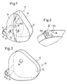
- the gas bag 10 of a restraint system for vehicles shown schematically in the almost fully inflated state in FIG. 1, is connected with its mouth opening 12 to the housing 14 of a gas generator 16.
- the airbag 10 consists of a middle jacket portion 18 and two side parts 20, 22.
- a fold 24 is formed on the side part 20 and extends almost over the entire height of the airbag.
- This fold 24 consists of two superimposed wall parts 24a, 24b.
- the fold 24 is formed in that the superimposed wall parts 24a, 24b are held against one another along a dividing line separating the interior of the gas bag from the inside of the fold.
- a seam is arranged along the dividing line 26, which can be a single or multiple seam in a quilted, warp or zigzag design.
- This seam has a precisely defined tear resistance that is tailored to the desired behavior of the gas bag.
- a relief opening 30 is formed in the wall part 24b of the fold 24. The relief opening 30 has no effect as long as the fold 24 is closed, since the gases inside the gas bag 10 remain blocked from access to the relief opening 30 as long as the inside of the fold 24 is separated from the interior of the gas bag by the seam along the dividing line 26.
- the gas bag When the gas generator 16 is activated, the gas bag is thrown out of the housing 14 and begins to unfold. In the almost completely unfolded state, it has approximately the shape shown in FIG. 1.
- the fold 24 remains closed until the gas bag internal pressure has reached a predetermined value. If the pressure inside the gas bag increases further, the seam tears along the dividing line 26, so that the fold 24 is opened. At the same time, access to the relief opening 30 is also free for the gases from the gas bag.
- the gas bag is now fully unfolded and takes on approximately the shape shown in FIG. 3. As long as it remains closed, the fold 24 on the side part 20 side shortens the extent of this side part in the exit direction of the gas bag.
- the direction of expansion of the gas bag is pivoted towards the fold 24 side. It has been found that such a fold can be used to change the direction of expansion of the gas bag by an angle of up to approximately 30 °. This value is sufficient to correct the direction of expansion of the airbag even in unfavorable installation situations so that it points approximately to the middle of the sitting position (assuming that the vehicle seat is in the middle position of the longitudinal displacement path).
- the fold 24 also shortens the entire outlet distance of the gas bag, since this fold, as long as it is closed, reduces the circumferential length of the gas bag.
- the fold 24 also reduces the exit speed of the gas bag in the final phase of its deployment. In addition to the primary aim of being able to control the outlet direction of the gas bag within a wide range, the fold 24 thus achieves two further, very desirable effects, namely a reduction in the outlet distance and a reduction in the axial outlet speed of the gas bag.
- a fourth, extremely important effect is that the relief opening 30 is controlled by the condition of the fold 24. It remains closed as long as the fold 24 is closed. No gases are lost until the gas bag is almost fully deployed.
- the gas bag has the great hardness desired in the initial phase of the restraining process.
- the relief opening 30 is only released after the fold 24 has opened and the gas bag has fully unfolded. In this phase of the restraining process, the compression path of the vehicle can be exhausted, so that energy absorption that mitigates the impact is only possible through the gas bag. This energy absorption is achieved by controlled outflow of the gases from the gas bag through the relief opening 30.
- the embodiment according to FIGS. 4 to 6 essentially differs from that according to FIGS. 1 to 3 in that the fold 24 is not arranged in a side part but on the jacket part 18. Since the fold 24 is further arranged in the lower section of the casing part 18, it causes the direction of propagation of the gas bag to be deflected downward. A relief opening is not shown in this embodiment, but can be provided if necessary.
- the fold 24 extends over the entire width of the jacket part 18. In this embodiment, too, the superimposed wall parts 24a, 24b of the fold 24 are connected by a seam along a dividing line 26.
- the superimposed wall parts of the fold are glued to one another or brought together by other suitable holding means, it only being important that these holding means are dimensioned in their strength so that the fold when a predetermined value of the gas bag internal pressure.
Landscapes
- Engineering & Computer Science (AREA)
- Mechanical Engineering (AREA)
- Air Bags (AREA)
Claims (7)
- Système de retenue pour les passagers d'un véhicule, comprenant un générateur de gaz (16) et un coussin à gaz (10) que l'on peut gonfler à l'aide de celui-ci, avec un pli (24) dans la paroi du coussin à gaz (10), qui est constitué grâce au fait que l'on maintient appliquées par une couture deux parties de paroi superposées (24a, 24b), qui sont dimensionnées, quant à leur résistance, de façon telle que le pli (24) se déchire lorsque la pression intérieure du coussin à gaz atteint une valeur prédéterminée, la couture s'étendant le long d'une ligne de séparation (26), qui sépare l'intérieur du coussin à gaz (10) de l'intérieur du pli (24), et le coussin à gaz (10) présentant, quand il est en position complètement gonflée, une forme dissymétrique, caractérisé en ce que le générateur de gaz (16) produit en cas de retenue une pression interne dans le coussin à gaz, qui atteint la valeur prédéterminée, et en ce que le coussin à gaz est disposé de façon excentrée par rapport à la position assise du passager du véhicule et en ce que dans ce cas, on corrige une direction excentrée de l'étirage du coussin à gaz (10) lors de son déploiement grâce à la couture positionnée et orientée en conséquence, de telle sorte que la direction de l'étirage est orientée vers le milieu de la position assise.
- Système de retenue pour les passagers d'un véhicule selon la revendication 1, caractérisé en ce que les moyens de fixation sont constitués par un collage.
- Système de retenue pour les passagers d'un véhicule selon l'une des revendications précédentes, comprenant un coussin à gaz (10), qui consiste en une enveloppe (18) et en deux parties latérales (20, 22), cousues avec celle-ci, caractérisé en ce que l'on dispose au moins un pli (24) dans la partie d'enveloppe (18) et/ou dans une partie latérale (20).
- Système de retenue pour les passagers d'un véhicule selon la revendication 3, caractérisé en ce que le pli (24) s'étend sur toute la largeur de la partie d'enveloppe (18).
- Système de retenue pour les passagers d'un véhicule selon la revendication 3 ou 4, caractérisé en ce qu'au moins un pli (24) s'étend sur l'une des parties latérales (20) au moins approximativement sur toute la hauteur de la partie latérale (20).
- Système de retenue pour les passagers d'un véhicule selon l'une des revendications précédentes, caractérisé en ce que dans au moins l'une des parties superposées de paroi (24a, 24b) du pli (24) il est formé au moins un orifice de décharge (30).
- Système de retenue pour les passagers d'un véhicule selon l'une des revendications précédentes, caractérisé en ce que la ligne de séparation (26) séparant le volume intérieur du coussin à gaz (10) de l'intérieur du pli (24) est orientée perpendiculairement à la direction d'éjection du coussin à gaz (10) lors de son déploiement.
Applications Claiming Priority (2)
| Application Number | Priority Date | Filing Date | Title |
|---|---|---|---|
| DE4101286A DE4101286A1 (de) | 1991-01-17 | 1991-01-17 | Aufblasbarer gassack fuer rueckhaltesysteme in fahrzeugen |
| DE4101286 | 1991-01-17 |
Publications (2)
| Publication Number | Publication Date |
|---|---|
| EP0495409A1 EP0495409A1 (fr) | 1992-07-22 |
| EP0495409B1 true EP0495409B1 (fr) | 1997-04-09 |
Family
ID=6423211
Family Applications (1)
| Application Number | Title | Priority Date | Filing Date |
|---|---|---|---|
| EP92100340A Expired - Lifetime EP0495409B1 (fr) | 1991-01-17 | 1992-01-10 | Coussin d'air gonflable pour un système de retenue dans des véhicules |
Country Status (10)
| Country | Link |
|---|---|
| US (1) | US5333903A (fr) |
| EP (1) | EP0495409B1 (fr) |
| JP (1) | JP3060021B2 (fr) |
| CN (1) | CN1063649A (fr) |
| CZ (1) | CZ282317B6 (fr) |
| DE (2) | DE4101286A1 (fr) |
| ES (1) | ES2032738T3 (fr) |
| HU (1) | HUT60198A (fr) |
| PL (1) | PL293166A1 (fr) |
| RU (1) | RU2041085C1 (fr) |
Cited By (2)
| Publication number | Priority date | Publication date | Assignee | Title |
|---|---|---|---|---|
| DE102004058438B3 (de) * | 2004-12-03 | 2006-05-11 | Trw Automotive Gmbh | Gassack für ein Fahrzeuginsassen-Rückhaltesystem |
| DE10161956B4 (de) * | 2001-01-08 | 2015-12-31 | Trw Vehicle Safety Systems Inc. | Fahrzeuginsassenschutzvorrichtung und Fahrzeuginsassenschutzsystem |
Families Citing this family (61)
| Publication number | Priority date | Publication date | Assignee | Title |
|---|---|---|---|---|
| MX9304559A (es) * | 1992-09-01 | 1994-03-31 | Morton Int Inc | Cuerdas con costuras rascables para cojin de bolsa inflable. |
| US5308113A (en) * | 1992-10-09 | 1994-05-03 | Trw Vehicle Safety Systems Inc. | Airbag inflation-controlling member |
| DE69400970T2 (de) * | 1993-03-11 | 1997-04-10 | Morton Int Inc | Beifahrerluftsack mit gesteuerter Entfaltung |
| US5395134A (en) * | 1993-04-02 | 1995-03-07 | Morton International, Inc. | Passenger side air bag with controlled deployment |
| US5478111A (en) * | 1993-08-11 | 1995-12-26 | Morton International, Inc. | Dynamic burn vents for the cushion of an air bag module |
| WO1995006574A1 (fr) * | 1993-08-31 | 1995-03-09 | Alliedsignal Inc. | Sac gonflable a motif a couture dechirable ameliore |
| JP3353424B2 (ja) * | 1993-11-25 | 2002-12-03 | タカタ株式会社 | エアバッグ及びエアバッグ装置 |
| JPH07205738A (ja) * | 1994-01-13 | 1995-08-08 | Toyo Tire & Rubber Co Ltd | 車両用エアバッグ |
| JP3321978B2 (ja) * | 1994-04-05 | 2002-09-09 | タカタ株式会社 | エアバッグ装置 |
| US5503429A (en) * | 1994-09-01 | 1996-04-02 | Trw Vehicle Safety Systems Inc. | Vehicle occupant restraint apparatus and method of assembly |
| DE19522765A1 (de) * | 1995-06-27 | 1997-01-02 | Pars Passive Rueckhaltesysteme | Airbagmodul |
| US5639118A (en) * | 1995-10-18 | 1997-06-17 | General Motors Corporation | Air bag module with inflation detection device |
| DE29517951U1 (de) * | 1995-11-13 | 1996-02-08 | Trw Repa Gmbh | Gassack für ein Fahrzeuginsassen-Rückhaltesystem |
| US5603526A (en) * | 1996-01-16 | 1997-02-18 | Morton International, Inc. | Pressure vent for air bag cushion |
| US5865467A (en) * | 1996-04-01 | 1999-02-02 | Toyo Tire & Rubber Co., Ltd. | Airbag for front seat passenger |
| JP3769831B2 (ja) * | 1996-04-08 | 2006-04-26 | タカタ株式会社 | エアバッグ及びエアバッグ装置 |
| US5803495A (en) * | 1996-04-22 | 1998-09-08 | Autoliv Asp, Inc. | Variable volume airbag cushion |
| JP3365204B2 (ja) * | 1996-05-07 | 2003-01-08 | 豊田合成株式会社 | エアバッグ装置のエアバッグ |
| US5725244A (en) * | 1996-07-09 | 1998-03-10 | Breed Automotive Technology, Inc. | Airbag venting mechanism |
| US5704639A (en) * | 1996-07-09 | 1998-01-06 | Breed Automotive Technology, Inc. | Pressure sensitive airbag vent mechanism |
| EP0835787A1 (fr) * | 1996-10-09 | 1998-04-15 | TRW Occupant Restraint Systems GmbH | Coussin gonflable pour un système de retenue des occupants d'un véhicule |
| DE19643052A1 (de) * | 1996-10-18 | 1997-09-04 | Daimler Benz Ag | Airbag, insbesondere in einem Kraftfahrzeug |
| DE19720584C2 (de) | 1997-05-16 | 2000-11-23 | Porsche Ag | Seitenaufprallschutzeinrichtung für einen Insassen eines Fahrzeuges |
| DE19720587A1 (de) * | 1997-05-16 | 1998-11-19 | Porsche Ag | Seitenaufprallschutzeinrichtung für einen Insassen eines Fahrzeuges |
| DE19720585A1 (de) * | 1997-05-16 | 1998-11-19 | Porsche Ag | Seitenaufprallschutzeinrichtung für einen Insassen eines Fahrzeuges |
| DE19720586C2 (de) * | 1997-05-16 | 2000-11-30 | Porsche Ag | Seitenaufprallschutzeinrichtung für einen Insassen eines Fahrzeuges |
| DE29713112U1 (de) * | 1997-07-23 | 1998-01-22 | Trw Repa Gmbh | Gassack-Rückhaltesystem |
| DE29801051U1 (de) * | 1998-01-22 | 1998-05-20 | Trw Repa Gmbh | Gassack für eine Seitenaufprall-Schutzeinrichtung |
| DE29804239U1 (de) * | 1998-03-10 | 1998-08-20 | Trw Repa Gmbh | Gassack für ein Fahrzeuginsassen-Rückhaltesystem |
| DE19903361A1 (de) * | 1999-01-28 | 2000-08-03 | Breed Automotive Tech | Verfahren zur Herstellung eines Luftsackes und Luftsack |
| US6497156B2 (en) * | 1999-12-28 | 2002-12-24 | Horiba Instruments, Inc. | Method for collecting exhaust gases |
| DE20003366U1 (de) * | 2000-02-24 | 2000-08-10 | Trw Repa Gmbh | Seitenaufprall-Schutzeinrichtung |
| US6659499B2 (en) | 2002-01-09 | 2003-12-09 | Trw Vehicle Safety Systems Inc. | Air bag with vent |
| JP4641880B2 (ja) * | 2005-07-06 | 2011-03-02 | 芦森工業株式会社 | 車両用エアバッグ |
| JP2007191103A (ja) * | 2006-01-20 | 2007-08-02 | Mazda Motor Corp | ピラーエアバッグ装置 |
| FR2900111B1 (fr) * | 2006-04-24 | 2011-02-11 | Trw Automotive Gmbh | Dispositif de retenue d'occupant de vehicule avec coussin a gaz. |
| DE102006027371A1 (de) * | 2006-06-13 | 2007-12-20 | Trw Automotive Gmbh | Aufblasbarer Gassack sowie Gassackmodul mit einem solchen Gassack |
| DE202006017996U1 (de) | 2006-11-22 | 2007-02-15 | Takata-Petri Ag | Gassack für ein Kraftfahrzeug |
| DE102007005304B4 (de) * | 2007-02-02 | 2010-11-11 | Autoliv Development Ab | Gassack |
| DE102007013101A1 (de) * | 2007-03-14 | 2007-08-16 | Takata-Petri Ag | Gefalteter Gassack für ein Kraftfahrzeug |
| JP2009056976A (ja) * | 2007-08-31 | 2009-03-19 | Toyoda Gosei Co Ltd | 助手席用エアバッグ |
| DE102007056137B4 (de) * | 2007-11-20 | 2015-05-13 | TAKATA Aktiengesellschaft | Gassack mit einem Einfüllstutzen und Gassackanordnung mit einem Gassack und einem Gasgenerator |
| EP2072348B1 (fr) * | 2007-12-18 | 2016-10-05 | Autoliv Development AB | Coussin d'air pour genoux et son procédé de pliage |
| DE102008018857B3 (de) * | 2008-04-15 | 2009-07-16 | Autoliv Development Ab | Gassack |
| DE102008048398B4 (de) * | 2008-09-19 | 2019-05-23 | Joyson Safety Systems Germany Gmbh | Gassack für ein Kraftfahrzeug |
| DE102009019766A1 (de) * | 2009-04-28 | 2010-01-28 | Takata-Petri Ag | Gassack für ein Fahrzeuginsassen-Rückhaltesystem und Verfahren zum Herstellen eines Fahrzeuginsassen-Rückhaltesystems |
| US8505969B2 (en) * | 2009-10-27 | 2013-08-13 | Tk Holdings Inc. | Knee airbag module |
| JP5387479B2 (ja) * | 2010-03-30 | 2014-01-15 | 豊田合成株式会社 | エアバッグ |
| JP5822541B2 (ja) * | 2011-06-01 | 2015-11-24 | タカタ株式会社 | エアバッグの製造方法及びエアバッグ装置の製造方法 |
| JP6092861B2 (ja) * | 2011-07-12 | 2017-03-08 | ティーケー ホールディングス インク.Tk Holdings Inc. | エアバッグ |
| GB201113411D0 (en) * | 2011-08-04 | 2011-09-21 | Ford Global Tech Llc | An airbag having a pressure responsive vent |
| US20130221644A1 (en) | 2012-02-23 | 2013-08-29 | Key Safety Systems, Inc. | Airbag with multi-state vent |
| DE102013003239B4 (de) | 2013-02-27 | 2019-03-21 | Autoliv Development Ab | Knieairbag |
| US9566935B2 (en) * | 2013-03-15 | 2017-02-14 | Autoliv Asp, Inc. | Double fold and roll cushions for IC |
| CN103661229B (zh) * | 2013-09-17 | 2016-05-18 | 锦州锦恒汽车安全系统有限公司 | 汽车安全气囊自适应排气孔结构 |
| DE102013017695A1 (de) * | 2013-10-24 | 2014-07-24 | Daimler Ag | Airbag für einen Kraftwagen |
| WO2016008708A1 (fr) * | 2014-07-16 | 2016-01-21 | Takata AG | Coussin de sécurité gonflable pour système de retenue de passager d'un véhicule |
| CN104760561A (zh) * | 2015-03-24 | 2015-07-08 | 上海东方久乐汽车安全气囊有限公司 | 一种前排乘员气囊 |
| DE102017212295A1 (de) | 2017-07-18 | 2019-01-24 | Volkswagen Aktiengesellschaft | Gassack für ein Fahrzeuginsassen-Rückhaltesystem |
| DE102017217499A1 (de) * | 2017-09-29 | 2019-04-04 | Joyson Safety Systems Germany Gmbh | Gassackeinheit für ein Kraftfahrzeug |
| KR102533286B1 (ko) * | 2018-04-04 | 2023-05-17 | 현대모비스 주식회사 | 운전석용 에어백 장치 |
Family Cites Families (10)
| Publication number | Priority date | Publication date | Assignee | Title |
|---|---|---|---|---|
| US3451693A (en) * | 1967-09-01 | 1969-06-24 | Eaton Yale & Towne | Vehicle safety method and apparatus |
| US3527475A (en) * | 1969-03-07 | 1970-09-08 | Eaton Yale & Towne | Vehicle safety system |
| DE2030863A1 (de) * | 1970-06-23 | 1971-12-30 | Klippan GmbH, 2000 Hamburg-Norderstedt | Mit einer Gaspatrone aufblasbares Luftkissen, insbesondere für Kraftfahrzeuge |
| US3797855A (en) * | 1972-04-10 | 1974-03-19 | Allied Chem | Bag deployment |
| US3810654A (en) * | 1972-05-05 | 1974-05-14 | Gen Motors Corp | Occupant restraint cushion assembly and method of manufacture |
| US3990726A (en) * | 1975-04-23 | 1976-11-09 | Nissan Motor Co., Ltd. | Inflatable and semi-crushable safety bag for vehicle passenger |
| JPS524371A (en) * | 1975-05-02 | 1977-01-13 | Shiyuusuke Wagou | Tube joint |
| DE2722551A1 (de) | 1977-05-18 | 1978-11-30 | Daimler Benz Ag | Aufblasbares aufprallschutzkissen |
| DE2944319A1 (de) * | 1979-11-02 | 1981-05-14 | Daimler-Benz Ag, 7000 Stuttgart | Aufblasbares aufprallschutzkissen |
| DE3818185C1 (fr) * | 1988-05-28 | 1989-08-17 | Daimler-Benz Aktiengesellschaft, 7000 Stuttgart, De |
-
1991
- 1991-01-17 DE DE4101286A patent/DE4101286A1/de not_active Withdrawn
-
1992
- 1992-01-10 EP EP92100340A patent/EP0495409B1/fr not_active Expired - Lifetime
- 1992-01-10 DE DE59208306T patent/DE59208306D1/de not_active Expired - Fee Related
- 1992-01-10 ES ES92100340T patent/ES2032738T3/es not_active Expired - Lifetime
- 1992-01-13 PL PL29316692A patent/PL293166A1/xx unknown
- 1992-01-16 HU HU9200148A patent/HUT60198A/hu unknown
- 1992-01-16 JP JP4005905A patent/JP3060021B2/ja not_active Expired - Fee Related
- 1992-01-16 CN CN92100277A patent/CN1063649A/zh active Pending
- 1992-01-16 RU SU925010783A patent/RU2041085C1/ru active
- 1992-01-17 CZ CS92147A patent/CZ282317B6/cs not_active IP Right Cessation
- 1992-01-17 US US07/822,074 patent/US5333903A/en not_active Expired - Lifetime
Cited By (2)
| Publication number | Priority date | Publication date | Assignee | Title |
|---|---|---|---|---|
| DE10161956B4 (de) * | 2001-01-08 | 2015-12-31 | Trw Vehicle Safety Systems Inc. | Fahrzeuginsassenschutzvorrichtung und Fahrzeuginsassenschutzsystem |
| DE102004058438B3 (de) * | 2004-12-03 | 2006-05-11 | Trw Automotive Gmbh | Gassack für ein Fahrzeuginsassen-Rückhaltesystem |
Also Published As
| Publication number | Publication date |
|---|---|
| EP0495409A1 (fr) | 1992-07-22 |
| DE59208306D1 (de) | 1997-05-15 |
| PL293166A1 (en) | 1992-09-07 |
| CN1063649A (zh) | 1992-08-19 |
| JPH04306147A (ja) | 1992-10-28 |
| HUT60198A (en) | 1992-08-28 |
| ES2032738T3 (es) | 1997-06-16 |
| JP3060021B2 (ja) | 2000-07-04 |
| HU9200148D0 (en) | 1992-04-28 |
| US5333903A (en) | 1994-08-02 |
| RU2041085C1 (ru) | 1995-08-09 |
| CZ282317B6 (cs) | 1997-06-11 |
| CS14792A3 (en) | 1992-09-16 |
| ES2032738T1 (es) | 1993-03-01 |
| DE4101286A1 (de) | 1992-07-23 |
Similar Documents
| Publication | Publication Date | Title |
|---|---|---|
| EP0495409B1 (fr) | Coussin d'air gonflable pour un système de retenue dans des véhicules | |
| EP0714818B1 (fr) | Coussin gonflable pour collision latérale | |
| DE60023205T2 (de) | Luftsack | |
| DE10018170B4 (de) | Luftsackanordnung | |
| DE19640322B4 (de) | Airbagmodul | |
| DE102004006185B4 (de) | Gassack zum Einbau in ein Kraftfahrzeug | |
| WO2008110610A1 (fr) | Système d'assise d'un véhicule automobile et procédé de protection d'un passager | |
| DE60023453T2 (de) | Gasgenerator mit zwei brennkammern | |
| DE4220499C2 (de) | Aufprallschutzsystem mit Gassack (Airbag) | |
| DE102009019930A1 (de) | Gassackmodul zum Schutz des Thorax- und Kopfbereichs eines Fahrzeuginsassen | |
| DE102004059085A1 (de) | Gassack für ein Airbagmodul eines Kraftfahrzeugs | |
| WO1996025309A1 (fr) | Module de sac de protection gonflable | |
| EP1745991B1 (fr) | Système de retenue d'un passager d'un véhicule avec un coussin gonflable | |
| DE102007013106A1 (de) | Fahrzeugsitzanordnung und Verfahren zum Schützen eines Fahrezuginsassen | |
| DE102006038125A1 (de) | Rückhaltesystem | |
| DE102008028389A1 (de) | Frontgassack und Ventileinrichtung | |
| WO2007045438A1 (fr) | Dispositif de protection contre les chocs lateraux | |
| DE102006038124B4 (de) | Rückhaltesystem für ein Kraftfahrzeug | |
| DE102007057016A1 (de) | Fahrzeugsitzanordnung und Verfahren zum Schützen eines Fahrzeuginsassen | |
| DE19724625B4 (de) | Aufprallschutz | |
| EP0844143B1 (fr) | Boítier avec logement de réception d'un coussin de sécurité plié et gonflable. | |
| DE102007026467B4 (de) | Seitenairbag mit einem in einem äußeren Gassack angeordneten Zweiten inneren Gassack | |
| EP1508485B1 (fr) | Module de coussin gonflable | |
| EP0841226A1 (fr) | Coussin gonflable. | |
| EP0992404B1 (fr) | Dispositif de coussin de sécurité |
Legal Events
| Date | Code | Title | Description |
|---|---|---|---|
| PUAI | Public reference made under article 153(3) epc to a published international application that has entered the european phase |
Free format text: ORIGINAL CODE: 0009012 |
|
| AK | Designated contracting states |
Kind code of ref document: A1 Designated state(s): DE ES FR GB IT SE |
|
| GBC | Gb: translation of claims filed (gb section 78(7)/1977) | ||
| EL | Fr: translation of claims filed | ||
| ITCL | It: translation for ep claims filed |
Representative=s name: DR. ING. A. RACHELI & C. |
|
| 17P | Request for examination filed |
Effective date: 19921105 |
|
| REG | Reference to a national code |
Ref country code: ES Ref legal event code: BA2A Ref document number: 2032738 Country of ref document: ES Kind code of ref document: T1 |
|
| 17Q | First examination report despatched |
Effective date: 19951002 |
|
| RAP1 | Party data changed (applicant data changed or rights of an application transferred) |
Owner name: TRW OCCUPANT RESTRAINT SYSTEMS GMBH |
|
| GRAG | Despatch of communication of intention to grant |
Free format text: ORIGINAL CODE: EPIDOS AGRA |
|
| GRAH | Despatch of communication of intention to grant a patent |
Free format text: ORIGINAL CODE: EPIDOS IGRA |
|
| GRAH | Despatch of communication of intention to grant a patent |
Free format text: ORIGINAL CODE: EPIDOS IGRA |
|
| GRAA | (expected) grant |
Free format text: ORIGINAL CODE: 0009210 |
|
| AK | Designated contracting states |
Kind code of ref document: B1 Designated state(s): DE ES FR GB IT SE |
|
| ITF | It: translation for a ep patent filed |
Owner name: 0508;09MIFRACHELI & C. S.R.L. |
|
| GBT | Gb: translation of ep patent filed (gb section 77(6)(a)/1977) |
Effective date: 19970415 |
|
| REF | Corresponds to: |
Ref document number: 59208306 Country of ref document: DE Date of ref document: 19970515 |
|
| REG | Reference to a national code |
Ref country code: ES Ref legal event code: FG2A Ref document number: 2032738 Country of ref document: ES Kind code of ref document: T3 |
|
| ET | Fr: translation filed | ||
| PG25 | Lapsed in a contracting state [announced via postgrant information from national office to epo] |
Ref country code: SE Free format text: LAPSE BECAUSE OF NON-PAYMENT OF DUE FEES Effective date: 19980111 |
|
| PLBE | No opposition filed within time limit |
Free format text: ORIGINAL CODE: 0009261 |
|
| STAA | Information on the status of an ep patent application or granted ep patent |
Free format text: STATUS: NO OPPOSITION FILED WITHIN TIME LIMIT |
|
| 26N | No opposition filed | ||
| EUG | Se: european patent has lapsed |
Ref document number: 92100340.6 |
|
| PGFP | Annual fee paid to national office [announced via postgrant information from national office to epo] |
Ref country code: GB Payment date: 20001211 Year of fee payment: 10 |
|
| PGFP | Annual fee paid to national office [announced via postgrant information from national office to epo] |
Ref country code: ES Payment date: 20010123 Year of fee payment: 10 |
|
| REG | Reference to a national code |
Ref country code: GB Ref legal event code: IF02 |
|
| PG25 | Lapsed in a contracting state [announced via postgrant information from national office to epo] |
Ref country code: GB Free format text: LAPSE BECAUSE OF NON-PAYMENT OF DUE FEES Effective date: 20020110 |
|
| PG25 | Lapsed in a contracting state [announced via postgrant information from national office to epo] |
Ref country code: ES Free format text: LAPSE BECAUSE OF NON-PAYMENT OF DUE FEES Effective date: 20020111 |
|
| GBPC | Gb: european patent ceased through non-payment of renewal fee |
Effective date: 20020110 |
|
| REG | Reference to a national code |
Ref country code: ES Ref legal event code: FD2A Effective date: 20031022 |
|
| PGFP | Annual fee paid to national office [announced via postgrant information from national office to epo] |
Ref country code: FR Payment date: 20050105 Year of fee payment: 14 |
|
| PG25 | Lapsed in a contracting state [announced via postgrant information from national office to epo] |
Ref country code: FR Free format text: LAPSE BECAUSE OF NON-PAYMENT OF DUE FEES Effective date: 20060131 |
|
| PGFP | Annual fee paid to national office [announced via postgrant information from national office to epo] |
Ref country code: IT Payment date: 20060131 Year of fee payment: 15 Ref country code: DE Payment date: 20060131 Year of fee payment: 15 |
|
| REG | Reference to a national code |
Ref country code: FR Ref legal event code: ST Effective date: 20060929 |
|
| PG25 | Lapsed in a contracting state [announced via postgrant information from national office to epo] |
Ref country code: DE Free format text: LAPSE BECAUSE OF NON-PAYMENT OF DUE FEES Effective date: 20070801 |
|
| PG25 | Lapsed in a contracting state [announced via postgrant information from national office to epo] |
Ref country code: IT Free format text: LAPSE BECAUSE OF NON-PAYMENT OF DUE FEES Effective date: 20070110 |