EP0487734B1 - Spritzgiessmaschine mit vorrichtung zum antrieb eines metallischen kernes - Google Patents
Spritzgiessmaschine mit vorrichtung zum antrieb eines metallischen kernes Download PDFInfo
- Publication number
- EP0487734B1 EP0487734B1 EP91909706A EP91909706A EP0487734B1 EP 0487734 B1 EP0487734 B1 EP 0487734B1 EP 91909706 A EP91909706 A EP 91909706A EP 91909706 A EP91909706 A EP 91909706A EP 0487734 B1 EP0487734 B1 EP 0487734B1
- Authority
- EP
- European Patent Office
- Prior art keywords
- mold
- movable
- servomotor
- core
- shaft
- Prior art date
- Legal status (The legal status is an assumption and is not a legal conclusion. Google has not performed a legal analysis and makes no representation as to the accuracy of the status listed.)
- Expired - Lifetime
Links
Images
Classifications
-
- B—PERFORMING OPERATIONS; TRANSPORTING
- B29—WORKING OF PLASTICS; WORKING OF SUBSTANCES IN A PLASTIC STATE IN GENERAL
- B29C—SHAPING OR JOINING OF PLASTICS; SHAPING OF MATERIAL IN A PLASTIC STATE, NOT OTHERWISE PROVIDED FOR; AFTER-TREATMENT OF THE SHAPED PRODUCTS, e.g. REPAIRING
- B29C45/00—Injection moulding, i.e. forcing the required volume of moulding material through a nozzle into a closed mould; Apparatus therefor
- B29C45/17—Component parts, details or accessories; Auxiliary operations
- B29C45/26—Moulds
- B29C45/33—Moulds having transversely, e.g. radially, movable mould parts
- B29C45/332—Mountings or guides therefor; Drives therefor
-
- B—PERFORMING OPERATIONS; TRANSPORTING
- B29—WORKING OF PLASTICS; WORKING OF SUBSTANCES IN A PLASTIC STATE IN GENERAL
- B29C—SHAPING OR JOINING OF PLASTICS; SHAPING OF MATERIAL IN A PLASTIC STATE, NOT OTHERWISE PROVIDED FOR; AFTER-TREATMENT OF THE SHAPED PRODUCTS, e.g. REPAIRING
- B29C45/00—Injection moulding, i.e. forcing the required volume of moulding material through a nozzle into a closed mould; Apparatus therefor
- B29C45/17—Component parts, details or accessories; Auxiliary operations
- B29C45/26—Moulds
- B29C45/2618—Moulds having screw-threaded mould walls
- B29C45/262—Moulds having screw-threaded mould walls provided with unscrewing drive means
-
- B—PERFORMING OPERATIONS; TRANSPORTING
- B29—WORKING OF PLASTICS; WORKING OF SUBSTANCES IN A PLASTIC STATE IN GENERAL
- B29C—SHAPING OR JOINING OF PLASTICS; SHAPING OF MATERIAL IN A PLASTIC STATE, NOT OTHERWISE PROVIDED FOR; AFTER-TREATMENT OF THE SHAPED PRODUCTS, e.g. REPAIRING
- B29C45/00—Injection moulding, i.e. forcing the required volume of moulding material through a nozzle into a closed mould; Apparatus therefor
- B29C45/17—Component parts, details or accessories; Auxiliary operations
- B29C45/26—Moulds
- B29C45/2681—Moulds with rotatable mould parts
-
- Y—GENERAL TAGGING OF NEW TECHNOLOGICAL DEVELOPMENTS; GENERAL TAGGING OF CROSS-SECTIONAL TECHNOLOGIES SPANNING OVER SEVERAL SECTIONS OF THE IPC; TECHNICAL SUBJECTS COVERED BY FORMER USPC CROSS-REFERENCE ART COLLECTIONS [XRACs] AND DIGESTS
- Y10—TECHNICAL SUBJECTS COVERED BY FORMER USPC
- Y10S—TECHNICAL SUBJECTS COVERED BY FORMER USPC CROSS-REFERENCE ART COLLECTIONS [XRACs] AND DIGESTS
- Y10S425/00—Plastic article or earthenware shaping or treating: apparatus
- Y10S425/058—Undercut
-
- Y—GENERAL TAGGING OF NEW TECHNOLOGICAL DEVELOPMENTS; GENERAL TAGGING OF CROSS-SECTIONAL TECHNOLOGIES SPANNING OVER SEVERAL SECTIONS OF THE IPC; TECHNICAL SUBJECTS COVERED BY FORMER USPC CROSS-REFERENCE ART COLLECTIONS [XRACs] AND DIGESTS
- Y10—TECHNICAL SUBJECTS COVERED BY FORMER USPC
- Y10S—TECHNICAL SUBJECTS COVERED BY FORMER USPC CROSS-REFERENCE ART COLLECTIONS [XRACs] AND DIGESTS
- Y10S425/00—Plastic article or earthenware shaping or treating: apparatus
- Y10S425/809—Seal, bottle caps only
Definitions
- the present invention relates to an injection molding machine.
- a molding cavity of a mold is filled with a molten resin, and the filler resin is cooled and solidified in the molding cavity, whereupon a product is obtained.
- the shape of the product is simple, the product can be taken out of the mold by only separating a movable-side mold half from a stationary-side mold half and pushing the product out of the movable-side mold half, such as is disclosed in JP-A-1-225525. If the product has an undercut portion, thread portion, or hollow portion, however, it sometimes cannot be taken out of the mold.
- the movable-side mold half may be prevented from moving away from the stationary-side mold half by the undercut portion of the product, or the product may be prevented from being pushed out of the movable-side mold half, due to the engagement between the thread portion or hollow portion of the product and its corresponding portion of the movable-side mold half.
- a mold in which a mold portion (movable core) corresponding to the undercut portion or the like of the product is movable with respect to the remaining portion of the mold.
- the movable core is separated from the movable- and stationary-side mold halves by being driven by means of a mechanical core drive mechanism, such as an angular pin, angular cam, etc., or a fluid-operated core drive mechanism, such as a hydraulic cylinder apparatus or pneumatic motor, whereby the movable-side mold half can be moved away from the stationary-side mold half, or the product can be released from the mold.
- a mechanical core drive mechanism such as an angular pin, angular cam, etc.
- a fluid-operated core drive mechanism such as a hydraulic cylinder apparatus or pneumatic motor
- a mold which includes a slide core attached to a movable-side mold half so as to be movable in a direction perpendicular to the mold opening and closing direction and used to mold the indentations of the product.
- a molten resin is filled into a molding cavity and solidified in a manner such that the slide core is locked in a molding position by means of a locking block.
- the movable-side mold half is moved away from the stationary-side mold half after the slide core is unlocked, whereby the slide core is disengaged from the product along an angular pin, which extends at an angle to the mold opening and closing direction and has one end fixed to the stationary-side mold half, so that the product can be pushed out of the mold.
- the mechanical core drive apparatus of this type has a simple construction, it can only linearly move the movable core.
- the movable core must to rotated, on the other hand, in drawing the product out of the movable core having a thread portion corresponding to the thread portion of the product. Accordingly, the mechanical core drive apparatus is not fit for the molding of the product having the thread portion.
- the fluid-operated core drive apparatus which requires a working fluid source and a tube for connecting the working fluid source and the core drive apparatus, is complicated in construction.
- the connection between the movable core and the core drive apparatus costs much labor, so that attaching the mold to the injection molding machine takes much time, resulting in lower operating efficiency.
- a control device for controlling the drive of the fluid-operated core drive apparatus is provided separately from a control device which is conventionally provided for the injection molding machine in order to control the operations of an injection unit, mold clamping unit, product takeout unit, etc.
- the operating timing, operating speed, or operating stroke of the movable core sometimes cannot be accurately controlled in association with molding cycles executed by means of the various units under the control of the latter control device.
- the object of the present invention is to provide an injection molding machine with a core drive apparatus capable of being easily connected with a movable core, which constitutes part of a mold used in molding a product having an undercut portion, thread portion, or hollow portion or the like, and accurately driving the movable core.
- an injection molding machine comprising a mold which can be clamped by a mold clamping unit having a movable platen, to provide a molding cavity for a product to be molded, and a control device for controlling the drive of a group of operating units including said mold clamping unit, characterised in that said mold further comprises a movable core drivable by a core drive apparatus away from said molding cavity from a molding position in which the core provides a shape in the molded product, to a retreated position so that the molded product can be taken out of the mold after molding is finished, the core drive apparatus including a servomotor having an output shaft operatively connected by connecting means to said movable core and the servomotor being connected electrically to said control device.
- the core drive apparatus servomotor is adapted to operate so as to rotate the output shaft thereof, with said connecting means including a driven shaft releasably fitted on the servomotor output shaft and rotatably supported by means of the mold, a screw shaft connected to the movable core and threadedly engaged with a tapped hole formed in the mold, and a transmission mechanism for transmitting the rotary force of the driven shaft to the screw shaft.
- the transmission mechanism may be formed of, for example, a pair of gears fixed individually to the driven shaft and the screw shaft and in mesh with each other.
- the core drive apparatus servomotor is adapted to operate so as to rotate the output shaft thereof, with said connecting means including a first driven shaft releasably fitted on the servomotor output shaft and rotatably supported by means of the mold, a second driven shaft rotatably supported by means of the mold, a screw shaft connected to the movable core and threadedly engaged with a tapped hole formed in the mold, a first transmission mechanism for transmitting the rotary force of the first driven shaft to the second driven shaft, and a second transmission mechanism for transmitting the rotary force of the second driven shaft to the screw shaft.
- said connecting means including a first driven shaft releasably fitted on the servomotor output shaft and rotatably supported by means of the mold, a second driven shaft rotatably supported by means of the mold, a screw shaft connected to the movable core and threadedly engaged with a tapped hole formed in the mold, a first transmission mechanism for transmitting the rotary force of the first driven shaft to the second driven shaft,
- the first transmission mechanism may be formed of, for example, a belt for operatively connecting the first driven shaft to the second driven shaft
- the second transmission mechanism may be formed of, for example, a pair of gears fixed individually to the second driven shaft and the screw shaft and in mesh with each other.
- the core drive apparatus servomotor is adapted to operate so as to move the output shaft thereof in the axial direction, with the connecting means including a connecting shaft removably attached to the movable core, and a connector for connecting the connecting shaft to the servomotor output shaft.
- the core drive apparatus is composed of the servomotor, which may be attached to the movable platen of the mold clamping unit, and the connecting means for connecting the movable core to the servomotor output shaft.
- the core drive apparatus and the movable core of the mold can be connected to each other by only connecting the movable core to the servomotor output shaft by means of the connecting means.
- the mold can be easily attached to the mold clamping unit.
- the connecting means includes the driven shaft, screw shaft, and transmission mechanism
- the core drive apparatus and the movable core can be connected to each other by only fitting the driven shaft, attached to the mold, on the servomotor output shaft, and on the other hand, connecting the driven shaft and the screw shaft by means of the transmission mechanism after screwing the screw shaft, connected to the movable core, into the tapped hole of the mold.
- the connecting means includes the first and second driven shafts, screw shaft, and first and second transmission mechanisms
- the core drive apparatus and the movable core can be easily connected to each other.
- the connecting means includes the connecting shaft and the connector, it is necessary only that the connecting shaft connected to the movable core be connected to the servomotor output shaft by means of the connector.
- the servomotor of the core drive apparatus is connected to the control device for controlling the drive of the unit group for executing molding cycles, so that the unit group and the servomotor can be operated under the control of the common control device.
- the movable core may, if desired, be accurately driven for a predetermined stroke with a predetermined timing and at a predetermined speed, in association with the molding cycles.
- an injection molding machine comprises a control device 60 and various units 70, which include an injection unit, a mold clamping unit, and a product takeout unit.
- the units 70 are operated under the control of the control device 60 to repeatedly execute molding cycles, which includes processes of mold clamping, metering, injection, dwell, cooling, mold opening, and product takeout.
- drive sources for the individual units 70 are formed of a servomotor each.
- the control device 60 is preferably formed of a computer numerical control device.
- the numerical control device 60 (not shown in detail) includes a first processor for numerical control, which is connected to a memory stored with numerical control programs, servo circuits for the various units, etc., and a second processor for a programmable machine controller, which is connected to a memory stored with sequence programs and the like.
- the control device 60 further includes a common memory accessible to both the first and second processors and stored with operation programs for molding cycle control, a data input device, input and output circuits, etc.
- the mold clamping unit includes a servomotor (not shown) for mold clamping and a movable platen 1, which is connected to a rear platen (not shown) through a toggle mechanism having two toggle links 2.
- the toggle links 2 bend and stretch to move the movable platen 1 toward and away from a stationary platen (not shown), thereby effecting mold closing and opening operations.
- Movable- and stationary-side mold halves hereinafter referred to as movable and stationary molds 10 and 20 are releasably attached to the movable and stationary platens, respectively.
- the movable mold 10 in conjunction with the stationary mold 20, defines one or more molding cavities which correspond to one or more molded pieces which have an undercut portion or portions, thread portion(s), or hollow portion(s).
- one or more movable cores corresponding to one or more undercut portions, thread portions, or hollow portions are movably attached to the movable or stationary mold 10 or 20 corresponding thereto.
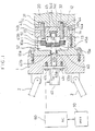
- the movable and stationary molds 10 and 20 define, respectively, first and second molding cavities 31 and 32 of the same shape and size used to form a cap (product) which has a bottomed tapped hole therein extending in the mold opening and closing direction.
- the movable mold 10 includes first and second movable cores 11 and 12, each having an external thread on the outer peripheral surface thereof mating with the tapped hole of each product, a mold mounting section 13 removably attached to the movable platen 1 by means of bolts (two of which are denoted by numeral 13a), and a movable mold body 14 fixed to that end face of the mold mounting section 13 on the side remoter from the movable platen by means of bolts (one of which is denoted by numeral 14a).
- the mold body 14 is formed having first and second tapped holes 14b and 14c, which extend penetrating the body 14 in the mold opening and closing direction (axial direction) and are aligned with the first and second molding cavities 31 and 32, respectively.
- Reference numeral 40 denotes a core drive apparatus for moving the first and second movable cores 11 and 12 in the axial direction.
- the core drive apparatus 40 comprises a servomotor 41 fixed to that end face of the movable platen 1 on the side remoter from the molds by means of bolts (two of which are denoted by numeral 41c), a driven shaft 42 rotatable by means of the motor 41, and first and second screw shafts 43 and 44 formed integrally with the first and second movable cores 11 and 12, respectively, at the stationary-mold-side end portions thereof.
- the apparatus 40 comprises a transmission mechanism 45 for transmitting the rotatory force of the driven shaft 42 to each of the first and second screw shafts 43 and 44.
- the servomotor 41 which is connected electrically to the output circuit of the control device 60, is operated under the control of the control device 60.
- the servomotor 41 has an output shaft 41a which extends penetrating an axial hole 1a formed in the central potion of the movable platen 1.
- the motor output shaft 41a terminates in an axial hole 13b, which is formed in the mold mounting section 13 so as to be in alignment with the movable platen axial hole 1a, and a projection 41b is formed on the distal end face of the shaft 41a.
- One end portion of the driven shaft 42 is rotatably supported on the mold mounting section 13 by means of a radial bearing disposed in the axial hole 13b, and a recess 42b to mate with the projection 41b is formed in the distal end face of the shaft 42.
- the other end portion of the driven shaft 42 is supported on the movable mold body 14 so as to be rotatable and axially immovable, by means of a radial bearing and a thrust bearing arranged in a bottomed hole 14d, which is formed in the inner end face of the movable body 14 so as to be in alignment with the axial hole 13b.
- the driven shaft 42 is rotatable integrally with the motor output shaft 41a.
- the first screw shaft 43 has the same external thread on its outer peripheral surface as the one formed on the first movable core 11, and is threadedly engaged with the tapped hole 14b formed in the movable mold body 14.
- the second screw shaft 44 has an outer peripheral surface with the same external thread as that of the second movable core 12, and is threadedly engaged with the tapped hole 14c.
- the first and second screw shafts 43 and 44 are axially movable along the tapped holes 14b and 14c, so that the first and second movable cords 11 and 12 can get into and out of the first and second molding cavities 31 and 32, respectively.
- the transmission mechanism 45 is composed of a main spur gear 45a, fixed to the middle portion of the driven shaft 42, and first and second auxiliary spur gears 45b and 45c fixed to the respective movable-platen-side ends of the first and second screw shafts 43 and 44, both the gears 45b and 45c being in mesh with the main gear 45a.
- Reference numerals 51 and 52 denote first and second position sensors, respectively, for detecting the moved position of the first movable core 11.
- the two sensors 51 and 52 which are each formed of, e.g., a limit switch, are connected electrically to the input circuit of the control device 60, and are isolatedly fixed on the inner surface of the peripheral wall of the movable mold mounting section 13. More specifically, the first limit switch 51 is fixed in a position such that it is turned on by means of that end face of the first auxiliary spur gear 45b on the side remoter from the movable platen when the distal end of the first movable core 11 takes a molding position in the first molding cavity 31.
- the second limit switch 52 is fixed in a position such that it is turned on by means of the movable-platen-side end face of the first auxiliary spur gear 45b when the distal end of the first movable core 11 leaves the first molding cavity 31.
- the molds, the movable core, and the position sensors are arranged so as to be fit for one specific type of molded pieces only.
- the injection molding machine operates in the conventional manner. More specifically, the various units of the injection molding machine are driven in accordance with the operation programs by means of the first and second processors of the numerical control device 60, whereby the molding cycles are repeatedly executed. During the execution of the molding cycles, both the processors refer, as required, to that one of mold files stored in the common memory which corresponds to the type of the mold used, so that the executed molding cycles are fit for the mold used.
- the second processor drives the servomotor 41 of the core drive apparatus 40 to rotate forward at a predetermined rotating speed.
- the main gear 45a fixed to the driven shaft 42 which is connected to the motor output shaft 41a, rotates forward, so that the first and second auxiliary gears 45b and 45c rotate forward.
- the first and second screw shafts 43 and 44 advance while rotating, so that the first and second movable cores 11 and 12 axially move from a retreated position to the molding position at a predetermined speed.
- the injection, dwell, and cooling processes are executed in succession, the first and second molding cavities 31 and 32 are filled with a molten resin, and the filler resin is cooled and solidified, whereupon a product is obtained.
- the mold opening process is started, whereupon a mold clamping motor is driven to move the movable platen 1 away from the stationary platen.
- the first processor monitors the moved position of the movable platen 1, and writes a mold opening completion signal in the common memory when the movable platen 1 reaches a mold opening completion position where it is separated from the stationary platen.
- the second processor drives the core drive motor 41 reversely, thereby retreating the first and second movable cores 11 and 12 from the molding position to the retreated position.
- the first movable core 11 reaches the retreated position, thereby turning on the second limit switch 52, the drive of the motor 41 is stopped, so that the first and second movable cores 11 and 12 are kept in the retreated position.
- the product takeout unit is actuated to take out the product from the movable mold 10.
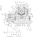
- the present embodiment differs from the first embodiment, in which the servomotor for core drive is attached to that end face of the movable platen on the opposite side to the mold mounting surface thereof, in that the servomotor for core drive is mounted on the top face of a movable platen.
- the servomotor for core drive is attached to that end face of the movable platen on the opposite side to the mold mounting surface thereof, so that a product takeout unit and the like can be easily arranged on the end face of the movable platen.
- the core drive apparatus is constructed in the same manner as the apparatus of Fig. 1. Therefore, like numerals are used to designate those components which are common to Figs. 1 and 2, and a description of the common components is omitted.
- the core drive apparatus 40' comprises the servomotor 41, fixed on the top face of the movable platen 1' by means of a bracket 40'a, and a first driven shaft 46 rotatably supported by means of a bracket 13'c which is fixed to the top face of a movable mold mounting section 13'.
- the driven shaft 46 is mounted on the bracket 13'c so as to be axially immovable by using suitable means (not shown).
- the motor output shaft 41a and the first driven shaft 46, each extending in the mold opening and closing direction, are arranged in alignment with each other, overlying the movable platen 1' and the mold mounting section 13'.
- Formed in the inner end face of the first driven shaft 46 is a recess 46b, which releasably mates with the projection 41b formed on the distal end face of the motor output shaft 41a.
- the core drive apparatus 40' further comprises a second driven shaft 42' similar to the driven shaft 42 of Fig. 1, and a first transmission mechanism formed of a belt 47 which operatively connects the first driven shaft 46 to the second driven shaft 42'.
- the second driven shaft 42' in conjunction with the first driven shaft 46 and the belt 47, fulfills the same function as the driven shaft 42 of Fig. 1.
- a through hole for the passage of the belt 47 is bored through each of the bracket 13'c and the top portion of the peripheral wall of the mold mounting section 13'.
- the core drive apparatus 40' comprises the first and second screw shafts 43 and 44 and the transmission mechanism (second transmission mechanism) 45, which have already been described with reference to Fig. 1.
- the core drive apparatus 40' operates substantially in the same manner as the core drive apparatus 40 of Fig. 1. Therefore, a description of the operation is omitted.
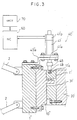
- the third embodiment differs from the first and second embodiments, in which the movable cores, each having the thread corresponding to the threaded portion of each product, is moved in the mold opening and closing direction while being rotated by means of the core drive servomotor which operates so as to rotate its output shaft, in that a movable core having a configuration corresponding to indentations on the outer peripheral surface of a product is linearly moved in a direction perpendicular to the mold opening and closing direction by means of a core drive servomotor which operates so as to rotate its output shaft in the axial direction.
- the movable core is operated for core removal to effect core-off molding, whereby a product with undercut portions can be satisfactorily manufactured.
- the present embodiment differs from the first and second embodiments in that there is no need of any component for converting the rotatory force of the motor output shaft to a linear driving force for the movable core.
- the core drive apparatus is simplified in construction and improved in operating accuracy.
- the core drive apparatus 40'' is mounted in an injection molding machine which is constructed basically in the same manner as the injection molding machines of the first and second embodiments.
- reference numerals 1'' and 2 denote a movable platen and toggle links, respectively, of a mold clamping unit, while numerals 60 and 70 denote a numerical control device and various units, respectively.
- numerals 10'' and 20' denote movable and stationary molds, respectively.
- the two molds 10'' and 20', in conjunction with the movable core 11', define a molding cavity 31' corresponding to a product which has indentations on its outer peripheral surface.
- the movable core 11' which has a molding cavity face for defining the indentations on the outer peripheral surface of the product, is attached to the stationary-mold-side end face of the movable mold 10'' so that it is slidable in the radial direction of the molds with respect to the movable mold 10''.
- the core drive apparatus 40'' comprises a through-type servomotor 41', whose motor output shaft 41'a is formed of a ball screw threadedly engaged with a ball nut, which is fixed to a hollow shaft, and reciprocates in the axial direction as the motor is operated.
- the servomotor 41' is fitted with a position sensor 41'b for generating feedback pulses in response to the movement of the output shaft 41'a.
- the position sensor 41'b is connected to the input circuit of the control device 60, and the control device 60 discriminates the moved position of the motor output shaft 41'a by the feedback pulses.
- the servomotor 41' is supported above the movable and stationary molds 10'' and 20' by means of a bracket 40''a, which is fixed to the top face of the movable platen 1'', and the motor output shaft 41'a extends in a direction (radial direction of the molds) perpendicular to the mold opening and closing direction.
- the core drive apparatus 40'' further comprises a shaft coupling 48 and a connecting shaft 49 for connecting the motor output shaft 41'a to the movable core 11'.
- the shaft coupling 48 which releasably connects the outer end portion of the connecting shaft 49 to the motor output shaft 41'a, is mounted on the distal end portion of the motor output shaft 41'a so as to be movable along the output shaft 41'a.
- the connecting shaft 49 has an inner end portion which has a thread on the outer peripheral surface thereof, mating with a tapped hole 11'a formed on the outer peripheral surface of the movable core 11', and the inner end portion of the shaft 49 is screwed in the movable core 11'.
- the servomotor 41' operates under the control of the numerical control device 60, so that the motor output shaft 41'a linearly moves toward the molds 10'' and 20' in the radial direction of the molds, whereupon the movable core 11' moves from its retreated position toward its molding position. If it is concluded in accordance with the feedback pulses from the position sensor 41'b that the molding position is reached by the distal end of the movable core 11', the rotation of the motor 41' is stopped, so that the movable core 11' ceases to move, and the molding cavity face of the movable core 11' is kept in the molding position. In this state, the injection, dwell, and cooling processes are executed to obtain the product.
- the servomotor 41' When the cooling process is finished, the servomotor 41' is driven so that the motor output shaft 41'a retreats, whereupon the movable core 11' retreats from the molding position to the retreated position. If it is concluded in accordance with the position sensor output that the retreated position is reached by the movable core 11', the drive of the motor 41' is stopped, so that the movable core 11' is kept in the retreated position. Then, the movable mold 10'' is moved away from the stationary mold 20', and the product is taken out of the movable mold 10'' after the completion of mold opening.
- the present invention is not limited to the first to third embodiments described above, and various modifications may be effected therein.
- each movable core used has a molding cavity face which corresponds in shape to the thread portion on the bottom face of each product or indentations on the outer peripheral surface of each product.
- the movable cores may be formed with various other molding cavities.
- each movable core is attached to the movable mold according to the embodiments, moreover, the movable core may alternatively be attached to the stationary mold.
- the core drive apparatus is provided with one servomotor.
- the core drive apparatus used may be one which includes a plurality of servomotors.
- the position sensors each formed of a limit switch are used for the movable core position detection.
- a position sensor formed of a pulse coder or the like for detecting the motor rotational position may be attached to the core drive servomotor.
Claims (8)
- Spritzgießmaschine, die eine Form (10, 20) umfaßt, welche mittels einer Klemmeinheit geklemmt werden kann, die eine bewegbare Platte (1) zum Schaffen eines Gießhohlraums für ein zu gießendes Erzeugnis und eine Steuereinrichtung (60) zum Steuern des Antriebs einer Gruppe von Betriebseinheiten (70) hat, welche die Formklemmeinheit enthalten, dadurch gekennzeichnet,
daß die Form (10, 20) ferner einen bewegbaren Kern (11, 12, 11') umfaßt, der mittels einer Kernantriebsvorrichtung (40, 40'. 40'') aus einer Gießposition heraus, in welcher der Kern (11, 12, 11') eine Form in dem gegossenen Erzeugnis schafft, fort von dem Formhohlraum hin zu einer zurückgezogenen Position bewegbar ist, so daß das gegossene Erzeugnis aus der Form entnommen werden kann, nachdem der Gießvorgang beendet ist, wobei die Kernantriebsvorrichtung (40, 40', 40'') einen Servomotor (41) enthält, der eine Ausgangswelle (41a) hat, die wirksam durch ein Verbindungsmittel mit dem bewegbaren Kern (11, 12, 11') verbunden ist, und wobei der Servomotor (41) elektrisch mit der Steuereinrichtung (60) verbunden ist. - Spritzgießmaschine nach Anspruch 1, bei der der Servomotor (41) an der bewegbaren Platte (1) angebracht ist.
- Spritzgießmaschine nach Anspruch 1 oder 2, bei der der Servomotor (41) der Kernantriebsvorrichtung dazu bestimmt ist, derart zu arbeiten, daß er dessen Ausgangswelle (41a) antreibt, und bei der das Verbindungsmittel der Kernantriebsvorrichtung (40) enthält: eine angetriebene Welle (42), die lösbar auf die Servomotor-Ausgangswelle (41a) gesetzt und drehbar mittels der Form gehalten ist, eine Schraubenwelle (43, 44), die mit dem bewegbaren Kern (11, 12) verbunden ist und mit einem Gewindeloch (14b, 14c) über Gewindegänge in Eingriff steht, das in der Form ausgebildet ist, und einen Übertragungsmechanismus zum Übertragen der Drehkraft der angetriebenen Wellle (42) auf die Schraubenwelle (43, 44).
- Spritzgießmaschine nach Anspruch 3, bei der der Übertragungsmechanismus aus einem Paar von Zahnrädern (45) gebildet ist, die einzelnen an der angetriebenen Welle (42) und der Schraubenwelle (43, 44) befestigt sind und mittels Verzahnung ineinandergreifen.
- Spritzgießmaschine nach Anspruch 1 oder 2, bei der der Servomotor (41) der Kernantriebsvorrichtung dazu bestimmt ist, derart zu arbeiten, daß er dessen Ausgangswelle (41a) dreht, und bei der das Verbindungsmittel der Kernantriebsvorrichtung (40') enthält; eine erste angetriebene Welle (46), die lösbar auf die Servomotor-Ausgangswelle (41a) gesetzt und drehbar mittels der Form gehalten ist, eine zweite angetriebene Welle (42a'), die drehbar mittels der Form gehalten ist, eine Schraubenwelle (43), die mit dem bewegbaren Kern (11, 12) verbunden ist und mit einem Gewindeloch über Gewindegänge in Eingriff steht, das in der Form ausgebildet ist, einen ersten Übertragungsmechanimus zum Übertragen der Drehkraft der ersten angetriebenen Welle (46) auf die zweite angetriebene Welle (42') und einen zweiten Übertragungsmechanismus zum Übertragen der Drehkraft der zweiten angetriebenen Welle (42') auf die Schraubenwelle (43, 44).
- Spritzgießmaschine nach Anspruch 5, bei der der erste Übertragungsmechanismus aus einem Treibriemen (47) zum wirksamen Verbinden der ersten angetriebenen Welle (46) mit der zweiten angetriebenen Welle (42') gebildet ist.
- Spritzgießmaschine nach Anspruch 5 oder 6, bei der der zweite Übertragungsmechanismus aus einem Paar von Zahnrädern (45) gebildet ist, die einzelnen an der zweiten angetriebenen Welle (42') und der Schraubenwelle (43, 44) befestigt sind und mittels Verzahnung ineinandergreifen.
- Spritzgießmaschine nach Anspruch 1 oder 2, bei der der Servomotor (41') der Kernantriebsvorrichtung dazu bestimmt ist, derart zu arbeiten, daß er dessen Ausgangswelle (41'a) in der axialen Richtung bewegt, und bei der das Verbindungsmittel der Kernantriebsvorrichtung (40'') enthält: eine Verbindungswelle (49), die abnehmbar an dem bewegbaren Kern (11') angebracht ist, und ein Verbindungselement (48) zum Verbinden der Verbindungswelle (49) mit der Servomotor-Ausgangswelle (41'a).
Applications Claiming Priority (3)
| Application Number | Priority Date | Filing Date | Title |
|---|---|---|---|
| JP156653/90 | 1990-06-16 | ||
| JP2156653A JP2649098B2 (ja) | 1990-06-16 | 1990-06-16 | コア駆動装置内蔵射出成形機 |
| PCT/JP1991/000694 WO1991019599A1 (en) | 1990-06-16 | 1991-05-23 | Injection molding machine provided with metallic core driving device |
Publications (3)
| Publication Number | Publication Date |
|---|---|
| EP0487734A1 EP0487734A1 (de) | 1992-06-03 |
| EP0487734A4 EP0487734A4 (en) | 1992-08-12 |
| EP0487734B1 true EP0487734B1 (de) | 1995-09-20 |
Family
ID=15632357
Family Applications (1)
| Application Number | Title | Priority Date | Filing Date |
|---|---|---|---|
| EP91909706A Expired - Lifetime EP0487734B1 (de) | 1990-06-16 | 1991-05-23 | Spritzgiessmaschine mit vorrichtung zum antrieb eines metallischen kernes |
Country Status (5)
| Country | Link |
|---|---|
| US (1) | US5310331A (de) |
| EP (1) | EP0487734B1 (de) |
| JP (1) | JP2649098B2 (de) |
| DE (1) | DE69113212T2 (de) |
| WO (1) | WO1991019599A1 (de) |
Families Citing this family (17)
| Publication number | Priority date | Publication date | Assignee | Title |
|---|---|---|---|---|
| JP2880072B2 (ja) * | 1994-05-13 | 1999-04-05 | エヌ・エス成形機販売株式会社 | 射出成形機のゲートカット及び突き出し制御装置及びアクチュエータ制御装置 |
| DE4444395C2 (de) * | 1994-11-28 | 1997-08-28 | Mannesmann Ag | Einrichtung zum Entfernen von spritzgegossenen Formteilen |
| US5865241A (en) * | 1997-04-09 | 1999-02-02 | Exco Technologies Limited | Die casting machine with precisely positionable obliquely moving die core pieces |
| US6079973A (en) * | 1998-03-27 | 2000-06-27 | Comar, Inc. | Apparatus for molding plastic caps |
| US6789301B1 (en) | 2001-03-21 | 2004-09-14 | Honda Motor Co., Ltd. | System and method for spotting movable mold cores |
| US6494706B2 (en) * | 2001-04-18 | 2002-12-17 | L. L. Culmat, Lp | Optical attenuator mold |
| US20040169320A1 (en) * | 2003-02-28 | 2004-09-02 | Petrucci Alan A. | Plastic injection mold assembly and method of molding threaded plastic parts |
| US7828541B2 (en) * | 2007-05-22 | 2010-11-09 | Coeur, Inc. | Motor driven mold |
| TWI457225B (zh) * | 2008-01-04 | 2014-10-21 | Hon Hai Prec Ind Co Ltd | 模具以及採用該模具注射成型之方法 |
| JP5426346B2 (ja) * | 2009-12-07 | 2014-02-26 | 東洋機械金属株式会社 | 射出成形機 |
| TW201134645A (en) * | 2010-04-15 | 2011-10-16 | Hon Hai Prec Ind Co Ltd | Ejecting mechanism and mold with same |
| JP5302277B2 (ja) * | 2010-08-09 | 2013-10-02 | 株式会社日本製鋼所 | 脱型装置および射出成形機 |
| TW201213090A (en) * | 2010-09-23 | 2012-04-01 | Hon Hai Prec Ind Co Ltd | Double mandril device of the injection molding machine |
| JP5161358B1 (ja) | 2011-10-06 | 2013-03-13 | ファナック株式会社 | ねじ抜き金型の回転中子制御装置 |
| AT514099B1 (de) * | 2013-03-27 | 2015-03-15 | Engel Austria Gmbh | Schließeinheit |
| EP3199320B1 (de) | 2016-02-01 | 2018-10-03 | The Procter and Gamble Company | Spritzgussvorrichtung |
| CN116568427A (zh) * | 2021-03-31 | 2023-08-08 | 住友重机械工业株式会社 | 可动压板 |
Citations (5)
| Publication number | Priority date | Publication date | Assignee | Title |
|---|---|---|---|---|
| JPS6110423A (ja) * | 1984-06-26 | 1986-01-17 | Fanuc Ltd | 射出成形機におけるエジェクタ−機構 |
| JPS6280016A (ja) * | 1985-10-03 | 1987-04-13 | Fanuc Ltd | 射出成形機における製品突出し機構 |
| JPS6471722A (en) * | 1987-09-11 | 1989-03-16 | Nissei Plastics Ind Co | Setting of projection starting position of molded form in molding machine |
| JPH01244816A (ja) * | 1988-03-26 | 1989-09-29 | Japan Steel Works Ltd:The | 電動射出成形機におけるエジエクタ制御方法およびその装置 |
| JPH0219520U (de) * | 1988-07-26 | 1990-02-08 |
Family Cites Families (20)
| Publication number | Priority date | Publication date | Assignee | Title |
|---|---|---|---|---|
| JPS4840899B1 (de) * | 1970-02-04 | 1973-12-03 | ||
| US4080148A (en) * | 1975-11-04 | 1978-03-21 | Amp Incorporated | Method and apparatus for manufacturing connectors attached together on a continuous carrier strip |
| US4159300A (en) * | 1975-11-04 | 1979-06-26 | Amp Incorporated | Method for manufacturing connectors in strip form |
| DE3110201A1 (de) * | 1981-03-17 | 1982-09-30 | Wolfgang 4800 Bielefeld Suttner | "vorrichtung zum herstellen von kunststoffkappen im spritzgussverfahren" |
| DE3237298C1 (de) * | 1982-10-08 | 1983-12-15 | Frömag Fröndenberger Maschinen-u.Apparatebau-Gesellschaft mbH, 5758 Fröndenberg | Vorrichtung zum Entfernen von gespritzten Kunststoffteilen mit Gewinden aus dem Werkzeug einer Spritzgiessmaschine |
| JPS5968220A (ja) * | 1982-10-12 | 1984-04-18 | Japan Crown Cork Co Ltd | 合成樹脂製容器蓋成形装置 |
| JPH0757511B2 (ja) * | 1986-03-08 | 1995-06-21 | フアナツク株式会社 | 射出成形機の製品取り出し装置の制御方法 |
| JP2519432B2 (ja) * | 1986-11-19 | 1996-07-31 | ファナック 株式会社 | 製品取出機の制御方法 |
| JPS648715A (en) * | 1987-06-30 | 1989-01-12 | Sharp Kk | Logic circuit device |
| JPS6468816A (en) * | 1987-09-10 | 1989-03-14 | Nissan Motor | Method for controlling dimensions of hygroscopic resin parts |
| JPH0529856Y2 (de) * | 1987-10-28 | 1993-07-30 | ||
| JPH01108715U (de) * | 1988-01-14 | 1989-07-24 | ||
| JPH0622826B2 (ja) * | 1988-03-04 | 1994-03-30 | 日精樹脂工業株式会社 | 射出圧縮成形方法および装置 |
| JPH01224816A (ja) * | 1988-03-04 | 1989-09-07 | Mitsubishi Electric Corp | 電源供給制御装置 |
| DE8806816U1 (de) * | 1988-05-25 | 1989-09-21 | Saurer-Allma Gmbh, 8960 Kempten, De | |
| JP2584287B2 (ja) * | 1988-08-29 | 1997-02-26 | ファナック株式会社 | トグル式型締装置 |
| US4988273A (en) * | 1989-06-23 | 1991-01-29 | Cincinnati Milacron Inc. | Injection molding machines having a brushless DC drive system |
| JP2610194B2 (ja) * | 1990-05-24 | 1997-05-14 | ファナック株式会社 | スライドコア付き金型 |
| JPH06110423A (ja) * | 1992-09-29 | 1994-04-22 | Ricoh Co Ltd | 販売支援装置 |
| JPH06280016A (ja) * | 1993-03-25 | 1994-10-04 | Kobe Steel Ltd | 連続真空蒸着めっきにおけるめっき原料供給装置 |
-
1990
- 1990-06-16 JP JP2156653A patent/JP2649098B2/ja not_active Expired - Lifetime
-
1991
- 1991-05-23 WO PCT/JP1991/000694 patent/WO1991019599A1/ja active IP Right Grant
- 1991-05-23 DE DE69113212T patent/DE69113212T2/de not_active Expired - Fee Related
- 1991-05-23 US US07/829,051 patent/US5310331A/en not_active Expired - Lifetime
- 1991-05-23 EP EP91909706A patent/EP0487734B1/de not_active Expired - Lifetime
Patent Citations (5)
| Publication number | Priority date | Publication date | Assignee | Title |
|---|---|---|---|---|
| JPS6110423A (ja) * | 1984-06-26 | 1986-01-17 | Fanuc Ltd | 射出成形機におけるエジェクタ−機構 |
| JPS6280016A (ja) * | 1985-10-03 | 1987-04-13 | Fanuc Ltd | 射出成形機における製品突出し機構 |
| JPS6471722A (en) * | 1987-09-11 | 1989-03-16 | Nissei Plastics Ind Co | Setting of projection starting position of molded form in molding machine |
| JPH01244816A (ja) * | 1988-03-26 | 1989-09-29 | Japan Steel Works Ltd:The | 電動射出成形機におけるエジエクタ制御方法およびその装置 |
| JPH0219520U (de) * | 1988-07-26 | 1990-02-08 |
Also Published As
| Publication number | Publication date |
|---|---|
| JPH0447914A (ja) | 1992-02-18 |
| WO1991019599A1 (en) | 1991-12-26 |
| DE69113212D1 (de) | 1995-10-26 |
| JP2649098B2 (ja) | 1997-09-03 |
| EP0487734A4 (en) | 1992-08-12 |
| DE69113212T2 (de) | 1996-02-22 |
| US5310331A (en) | 1994-05-10 |
| EP0487734A1 (de) | 1992-06-03 |
Similar Documents
| Publication | Publication Date | Title |
|---|---|---|
| EP0487734B1 (de) | Spritzgiessmaschine mit vorrichtung zum antrieb eines metallischen kernes | |
| US5911924A (en) | Process for injection molding machine with electric drives | |
| US20050281908A1 (en) | Clamping machine | |
| KR101135556B1 (ko) | 성형기 | |
| JPH09193162A (ja) | 複合式型締装置の型厚調整方法および装置 | |
| EP0281637B1 (de) | Unmittelbar wirkende formschliessvorrichtung für eine spritzgiessmaschine | |
| US8229591B2 (en) | Method for sequence programming of an injection molding cycle of an injection molding machine | |
| EP1136224B1 (de) | Produktauswurfvorrichtung und Verfahren für eine Spritzgiessanlage | |
| US4828476A (en) | Direct-pressure type mold clamping mechanism of an injection-molding machine | |
| KR100209445B1 (ko) | 금형 결합장치 | |
| JP6867978B2 (ja) | 射出成形機及びその成形方法 | |
| JP2838772B2 (ja) | 射出成形金型装置 | |
| JPH029614A (ja) | 電動式射出成形機の射出圧縮制御方法およびその装置 | |
| EP0338086B1 (de) | Verdichter für einspritzgiessmaschinen | |
| WO2009079748A1 (en) | An ejector assembly for ejecting parts from a mold | |
| JP4373334B2 (ja) | 成形機及びその制御方法 | |
| US9138926B2 (en) | Apparatus and method for injection molding | |
| JP2004001470A (ja) | 射出成形機等の型締方法および装置 | |
| JP2691639B2 (ja) | 金型のスライドコア駆動装置 | |
| JP2610194B2 (ja) | スライドコア付き金型 | |
| JPH0622826B2 (ja) | 射出圧縮成形方法および装置 | |
| JPH07110510B2 (ja) | トグル式射出成形機の型締力設定方法 | |
| JP2528508Y2 (ja) | 射出成形機用ネジ抜き装置 | |
| JPH0235470Y2 (de) | ||
| JPH05286001A (ja) | 電動射出成形機における金型内突出板の突出前進限位置確認方法及び装置 |
Legal Events
| Date | Code | Title | Description |
|---|---|---|---|
| PUAI | Public reference made under article 153(3) epc to a published international application that has entered the european phase |
Free format text: ORIGINAL CODE: 0009012 |
|
| 17P | Request for examination filed |
Effective date: 19920306 |
|
| AK | Designated contracting states |
Kind code of ref document: A1 Designated state(s): CH DE IT LI |
|
| A4 | Supplementary search report drawn up and despatched |
Effective date: 19920619 |
|
| AK | Designated contracting states |
Kind code of ref document: A4 Designated state(s): CH DE IT LI |
|
| 17Q | First examination report despatched |
Effective date: 19940328 |
|
| GRAA | (expected) grant |
Free format text: ORIGINAL CODE: 0009210 |
|
| AK | Designated contracting states |
Kind code of ref document: B1 Designated state(s): CH DE IT LI |
|
| PG25 | Lapsed in a contracting state [announced via postgrant information from national office to epo] |
Ref country code: LI Effective date: 19950920 Ref country code: CH Effective date: 19950920 |
|
| REF | Corresponds to: |
Ref document number: 69113212 Country of ref document: DE Date of ref document: 19951026 |
|
| ITF | It: translation for a ep patent filed |
Owner name: ING. ZINI MARANESI & C. S.R.L. |
|
| REG | Reference to a national code |
Ref country code: CH Ref legal event code: PL |
|
| PLBE | No opposition filed within time limit |
Free format text: ORIGINAL CODE: 0009261 |
|
| STAA | Information on the status of an ep patent application or granted ep patent |
Free format text: STATUS: NO OPPOSITION FILED WITHIN TIME LIMIT |
|
| 26N | No opposition filed | ||
| PGFP | Annual fee paid to national office [announced via postgrant information from national office to epo] |
Ref country code: DE Payment date: 20000522 Year of fee payment: 10 |
|
| PG25 | Lapsed in a contracting state [announced via postgrant information from national office to epo] |
Ref country code: DE Free format text: LAPSE BECAUSE OF NON-PAYMENT OF DUE FEES Effective date: 20020301 |
|
| PG25 | Lapsed in a contracting state [announced via postgrant information from national office to epo] |
Ref country code: IT Free format text: LAPSE BECAUSE OF NON-PAYMENT OF DUE FEES Effective date: 20050523 |