EP0427384A2 - Verfahren zum Verbinden eines TAB-Bandes an einem Halbleiterchip - Google Patents
Verfahren zum Verbinden eines TAB-Bandes an einem Halbleiterchip Download PDFInfo
- Publication number
- EP0427384A2 EP0427384A2 EP90309807A EP90309807A EP0427384A2 EP 0427384 A2 EP0427384 A2 EP 0427384A2 EP 90309807 A EP90309807 A EP 90309807A EP 90309807 A EP90309807 A EP 90309807A EP 0427384 A2 EP0427384 A2 EP 0427384A2
- Authority
- EP
- European Patent Office
- Prior art keywords
- bumps
- semiconductor chip
- tape
- tab tape
- bump
- Prior art date
- Legal status (The legal status is an assumption and is not a legal conclusion. Google has not performed a legal analysis and makes no representation as to the accuracy of the status listed.)
- Granted
Links
- 239000004065 semiconductor Substances 0.000 title claims abstract description 78
- 238000000034 method Methods 0.000 title claims abstract description 62
- 239000000758 substrate Substances 0.000 claims description 70
- 229910052751 metal Inorganic materials 0.000 claims description 14
- 239000002184 metal Substances 0.000 claims description 14
- 229920003002 synthetic resin Polymers 0.000 claims description 13
- 239000000057 synthetic resin Substances 0.000 claims description 13
- 239000010931 gold Substances 0.000 description 35
- PCHJSUWPFVWCPO-UHFFFAOYSA-N gold Chemical compound [Au] PCHJSUWPFVWCPO-UHFFFAOYSA-N 0.000 description 34
- 229910052737 gold Inorganic materials 0.000 description 34
- 230000000875 corresponding effect Effects 0.000 description 14
- 238000004519 manufacturing process Methods 0.000 description 13
- 229920001721 polyimide Polymers 0.000 description 13
- 239000010935 stainless steel Substances 0.000 description 12
- 229910001220 stainless steel Inorganic materials 0.000 description 12
- 239000002585 base Substances 0.000 description 10
- 239000004642 Polyimide Substances 0.000 description 8
- 229920005989 resin Polymers 0.000 description 8
- 239000011347 resin Substances 0.000 description 8
- RYGMFSIKBFXOCR-UHFFFAOYSA-N Copper Chemical compound [Cu] RYGMFSIKBFXOCR-UHFFFAOYSA-N 0.000 description 7
- 238000007747 plating Methods 0.000 description 7
- 239000000463 material Substances 0.000 description 6
- 230000015572 biosynthetic process Effects 0.000 description 5
- 238000007796 conventional method Methods 0.000 description 4
- 229910052802 copper Inorganic materials 0.000 description 4
- 239000010949 copper Substances 0.000 description 4
- HEMHJVSKTPXQMS-UHFFFAOYSA-M Sodium hydroxide Chemical compound [OH-].[Na+] HEMHJVSKTPXQMS-UHFFFAOYSA-M 0.000 description 3
- 229910045601 alloy Inorganic materials 0.000 description 3
- 239000000956 alloy Substances 0.000 description 3
- 239000011889 copper foil Substances 0.000 description 3
- 238000005530 etching Methods 0.000 description 3
- 239000012634 fragment Substances 0.000 description 3
- 238000010438 heat treatment Methods 0.000 description 3
- 229920000728 polyester Polymers 0.000 description 3
- 239000002904 solvent Substances 0.000 description 3
- 239000000853 adhesive Substances 0.000 description 2
- 230000001070 adhesive effect Effects 0.000 description 2
- 239000011888 foil Substances 0.000 description 2
- 239000011521 glass Substances 0.000 description 2
- 239000012212 insulator Substances 0.000 description 2
- 238000002844 melting Methods 0.000 description 2
- 239000000203 mixture Substances 0.000 description 2
- 230000010355 oscillation Effects 0.000 description 2
- 239000002994 raw material Substances 0.000 description 2
- 229910000927 Ge alloy Inorganic materials 0.000 description 1
- 239000004698 Polyethylene Substances 0.000 description 1
- ATJFFYVFTNAWJD-UHFFFAOYSA-N Tin Chemical compound [Sn] ATJFFYVFTNAWJD-UHFFFAOYSA-N 0.000 description 1
- BYDQGSVXQDOSJJ-UHFFFAOYSA-N [Ge].[Au] Chemical compound [Ge].[Au] BYDQGSVXQDOSJJ-UHFFFAOYSA-N 0.000 description 1
- 239000003513 alkali Substances 0.000 description 1
- 229910052782 aluminium Inorganic materials 0.000 description 1
- XAGFODPZIPBFFR-UHFFFAOYSA-N aluminium Chemical compound [Al] XAGFODPZIPBFFR-UHFFFAOYSA-N 0.000 description 1
- 238000007664 blowing Methods 0.000 description 1
- 238000007906 compression Methods 0.000 description 1
- 239000004020 conductor Substances 0.000 description 1
- 238000011109 contamination Methods 0.000 description 1
- 238000005520 cutting process Methods 0.000 description 1
- 230000006866 deterioration Effects 0.000 description 1
- 230000000694 effects Effects 0.000 description 1
- 238000007772 electroless plating Methods 0.000 description 1
- 229910052732 germanium Inorganic materials 0.000 description 1
- GNPVGFCGXDBREM-UHFFFAOYSA-N germanium atom Chemical compound [Ge] GNPVGFCGXDBREM-UHFFFAOYSA-N 0.000 description 1
- 230000010354 integration Effects 0.000 description 1
- 230000001678 irradiating effect Effects 0.000 description 1
- 238000010030 laminating Methods 0.000 description 1
- 238000003754 machining Methods 0.000 description 1
- 230000008018 melting Effects 0.000 description 1
- 239000002245 particle Substances 0.000 description 1
- 229920006267 polyester film Polymers 0.000 description 1
- -1 polyethylene Polymers 0.000 description 1
- 229920000573 polyethylene Polymers 0.000 description 1
- 238000003825 pressing Methods 0.000 description 1
- 238000004080 punching Methods 0.000 description 1
- 235000011121 sodium hydroxide Nutrition 0.000 description 1
- 238000007711 solidification Methods 0.000 description 1
- 230000008023 solidification Effects 0.000 description 1
- 125000006850 spacer group Chemical group 0.000 description 1
- 238000004544 sputter deposition Methods 0.000 description 1
- 238000010408 sweeping Methods 0.000 description 1
Images


Classifications
-
- H—ELECTRICITY
- H01—ELECTRIC ELEMENTS
- H01L—SEMICONDUCTOR DEVICES NOT COVERED BY CLASS H10
- H01L24/00—Arrangements for connecting or disconnecting semiconductor or solid-state bodies; Methods or apparatus related thereto
- H01L24/74—Apparatus for manufacturing arrangements for connecting or disconnecting semiconductor or solid-state bodies
- H01L24/79—Apparatus for Tape Automated Bonding [TAB]
-
- H—ELECTRICITY
- H01—ELECTRIC ELEMENTS
- H01L—SEMICONDUCTOR DEVICES NOT COVERED BY CLASS H10
- H01L21/00—Processes or apparatus adapted for the manufacture or treatment of semiconductor or solid state devices or of parts thereof
- H01L21/02—Manufacture or treatment of semiconductor devices or of parts thereof
- H01L21/04—Manufacture or treatment of semiconductor devices or of parts thereof the devices having potential barriers, e.g. a PN junction, depletion layer or carrier concentration layer
- H01L21/48—Manufacture or treatment of parts, e.g. containers, prior to assembly of the devices, using processes not provided for in a single one of the subgroups H01L21/06 - H01L21/326
- H01L21/4814—Conductive parts
- H01L21/4846—Leads on or in insulating or insulated substrates, e.g. metallisation
- H01L21/4853—Connection or disconnection of other leads to or from a metallisation, e.g. pins, wires, bumps
-
- H—ELECTRICITY
- H01—ELECTRIC ELEMENTS
- H01L—SEMICONDUCTOR DEVICES NOT COVERED BY CLASS H10
- H01L21/00—Processes or apparatus adapted for the manufacture or treatment of semiconductor or solid state devices or of parts thereof
- H01L21/02—Manufacture or treatment of semiconductor devices or of parts thereof
- H01L21/04—Manufacture or treatment of semiconductor devices or of parts thereof the devices having potential barriers, e.g. a PN junction, depletion layer or carrier concentration layer
- H01L21/50—Assembly of semiconductor devices using processes or apparatus not provided for in a single one of the subgroups H01L21/06 - H01L21/326, e.g. sealing of a cap to a base of a container
- H01L21/60—Attaching or detaching leads or other conductive members, to be used for carrying current to or from the device in operation
-
- H—ELECTRICITY
- H01—ELECTRIC ELEMENTS
- H01L—SEMICONDUCTOR DEVICES NOT COVERED BY CLASS H10
- H01L23/00—Details of semiconductor or other solid state devices
- H01L23/48—Arrangements for conducting electric current to or from the solid state body in operation, e.g. leads, terminal arrangements ; Selection of materials therefor
- H01L23/488—Arrangements for conducting electric current to or from the solid state body in operation, e.g. leads, terminal arrangements ; Selection of materials therefor consisting of soldered or bonded constructions
- H01L23/495—Lead-frames or other flat leads
- H01L23/49572—Lead-frames or other flat leads consisting of thin flexible metallic tape with or without a film carrier
-
- H—ELECTRICITY
- H01—ELECTRIC ELEMENTS
- H01L—SEMICONDUCTOR DEVICES NOT COVERED BY CLASS H10
- H01L24/00—Arrangements for connecting or disconnecting semiconductor or solid-state bodies; Methods or apparatus related thereto
- H01L24/01—Means for bonding being attached to, or being formed on, the surface to be connected, e.g. chip-to-package, die-attach, "first-level" interconnects; Manufacturing methods related thereto
- H01L24/10—Bump connectors ; Manufacturing methods related thereto
- H01L24/11—Manufacturing methods
-
- H—ELECTRICITY
- H01—ELECTRIC ELEMENTS
- H01L—SEMICONDUCTOR DEVICES NOT COVERED BY CLASS H10
- H01L24/00—Arrangements for connecting or disconnecting semiconductor or solid-state bodies; Methods or apparatus related thereto
- H01L24/01—Means for bonding being attached to, or being formed on, the surface to be connected, e.g. chip-to-package, die-attach, "first-level" interconnects; Manufacturing methods related thereto
- H01L24/10—Bump connectors ; Manufacturing methods related thereto
- H01L24/12—Structure, shape, material or disposition of the bump connectors prior to the connecting process
- H01L24/13—Structure, shape, material or disposition of the bump connectors prior to the connecting process of an individual bump connector
-
- H—ELECTRICITY
- H01—ELECTRIC ELEMENTS
- H01L—SEMICONDUCTOR DEVICES NOT COVERED BY CLASS H10
- H01L24/00—Arrangements for connecting or disconnecting semiconductor or solid-state bodies; Methods or apparatus related thereto
- H01L24/01—Means for bonding being attached to, or being formed on, the surface to be connected, e.g. chip-to-package, die-attach, "first-level" interconnects; Manufacturing methods related thereto
- H01L24/50—Tape automated bonding [TAB] connectors, i.e. film carriers; Manufacturing methods related thereto
-
- H—ELECTRICITY
- H01—ELECTRIC ELEMENTS
- H01L—SEMICONDUCTOR DEVICES NOT COVERED BY CLASS H10
- H01L24/00—Arrangements for connecting or disconnecting semiconductor or solid-state bodies; Methods or apparatus related thereto
- H01L24/80—Methods for connecting semiconductor or other solid state bodies using means for bonding being attached to, or being formed on, the surface to be connected
- H01L24/86—Methods for connecting semiconductor or other solid state bodies using means for bonding being attached to, or being formed on, the surface to be connected using tape automated bonding [TAB]
-
- H—ELECTRICITY
- H01—ELECTRIC ELEMENTS
- H01L—SEMICONDUCTOR DEVICES NOT COVERED BY CLASS H10
- H01L2224/00—Indexing scheme for arrangements for connecting or disconnecting semiconductor or solid-state bodies and methods related thereto as covered by H01L24/00
- H01L2224/01—Means for bonding being attached to, or being formed on, the surface to be connected, e.g. chip-to-package, die-attach, "first-level" interconnects; Manufacturing methods related thereto
- H01L2224/10—Bump connectors; Manufacturing methods related thereto
- H01L2224/11—Manufacturing methods
- H01L2224/113—Manufacturing methods by local deposition of the material of the bump connector
- H01L2224/1133—Manufacturing methods by local deposition of the material of the bump connector in solid form
- H01L2224/11334—Manufacturing methods by local deposition of the material of the bump connector in solid form using preformed bumps
-
- H—ELECTRICITY
- H01—ELECTRIC ELEMENTS
- H01L—SEMICONDUCTOR DEVICES NOT COVERED BY CLASS H10
- H01L2224/00—Indexing scheme for arrangements for connecting or disconnecting semiconductor or solid-state bodies and methods related thereto as covered by H01L24/00
- H01L2224/01—Means for bonding being attached to, or being formed on, the surface to be connected, e.g. chip-to-package, die-attach, "first-level" interconnects; Manufacturing methods related thereto
- H01L2224/10—Bump connectors; Manufacturing methods related thereto
- H01L2224/12—Structure, shape, material or disposition of the bump connectors prior to the connecting process
- H01L2224/13—Structure, shape, material or disposition of the bump connectors prior to the connecting process of an individual bump connector
- H01L2224/13001—Core members of the bump connector
- H01L2224/13099—Material
-
- H—ELECTRICITY
- H01—ELECTRIC ELEMENTS
- H01L—SEMICONDUCTOR DEVICES NOT COVERED BY CLASS H10
- H01L2224/00—Indexing scheme for arrangements for connecting or disconnecting semiconductor or solid-state bodies and methods related thereto as covered by H01L24/00
- H01L2224/01—Means for bonding being attached to, or being formed on, the surface to be connected, e.g. chip-to-package, die-attach, "first-level" interconnects; Manufacturing methods related thereto
- H01L2224/10—Bump connectors; Manufacturing methods related thereto
- H01L2224/15—Structure, shape, material or disposition of the bump connectors after the connecting process
- H01L2224/16—Structure, shape, material or disposition of the bump connectors after the connecting process of an individual bump connector
- H01L2224/161—Disposition
- H01L2224/16151—Disposition the bump connector connecting between a semiconductor or solid-state body and an item not being a semiconductor or solid-state body, e.g. chip-to-substrate, chip-to-passive
- H01L2224/16221—Disposition the bump connector connecting between a semiconductor or solid-state body and an item not being a semiconductor or solid-state body, e.g. chip-to-substrate, chip-to-passive the body and the item being stacked
- H01L2224/16225—Disposition the bump connector connecting between a semiconductor or solid-state body and an item not being a semiconductor or solid-state body, e.g. chip-to-substrate, chip-to-passive the body and the item being stacked the item being non-metallic, e.g. insulating substrate with or without metallisation
- H01L2224/16237—Disposition the bump connector connecting between a semiconductor or solid-state body and an item not being a semiconductor or solid-state body, e.g. chip-to-substrate, chip-to-passive the body and the item being stacked the item being non-metallic, e.g. insulating substrate with or without metallisation the bump connector connecting to a bonding area disposed in a recess of the surface of the item
-
- H—ELECTRICITY
- H01—ELECTRIC ELEMENTS
- H01L—SEMICONDUCTOR DEVICES NOT COVERED BY CLASS H10
- H01L2924/00—Indexing scheme for arrangements or methods for connecting or disconnecting semiconductor or solid-state bodies as covered by H01L24/00
- H01L2924/01—Chemical elements
- H01L2924/01006—Carbon [C]
-
- H—ELECTRICITY
- H01—ELECTRIC ELEMENTS
- H01L—SEMICONDUCTOR DEVICES NOT COVERED BY CLASS H10
- H01L2924/00—Indexing scheme for arrangements or methods for connecting or disconnecting semiconductor or solid-state bodies as covered by H01L24/00
- H01L2924/01—Chemical elements
- H01L2924/01013—Aluminum [Al]
-
- H—ELECTRICITY
- H01—ELECTRIC ELEMENTS
- H01L—SEMICONDUCTOR DEVICES NOT COVERED BY CLASS H10
- H01L2924/00—Indexing scheme for arrangements or methods for connecting or disconnecting semiconductor or solid-state bodies as covered by H01L24/00
- H01L2924/01—Chemical elements
- H01L2924/01015—Phosphorus [P]
-
- H—ELECTRICITY
- H01—ELECTRIC ELEMENTS
- H01L—SEMICONDUCTOR DEVICES NOT COVERED BY CLASS H10
- H01L2924/00—Indexing scheme for arrangements or methods for connecting or disconnecting semiconductor or solid-state bodies as covered by H01L24/00
- H01L2924/01—Chemical elements
- H01L2924/01029—Copper [Cu]
-
- H—ELECTRICITY
- H01—ELECTRIC ELEMENTS
- H01L—SEMICONDUCTOR DEVICES NOT COVERED BY CLASS H10
- H01L2924/00—Indexing scheme for arrangements or methods for connecting or disconnecting semiconductor or solid-state bodies as covered by H01L24/00
- H01L2924/01—Chemical elements
- H01L2924/01032—Germanium [Ge]
-
- H—ELECTRICITY
- H01—ELECTRIC ELEMENTS
- H01L—SEMICONDUCTOR DEVICES NOT COVERED BY CLASS H10
- H01L2924/00—Indexing scheme for arrangements or methods for connecting or disconnecting semiconductor or solid-state bodies as covered by H01L24/00
- H01L2924/01—Chemical elements
- H01L2924/01033—Arsenic [As]
-
- H—ELECTRICITY
- H01—ELECTRIC ELEMENTS
- H01L—SEMICONDUCTOR DEVICES NOT COVERED BY CLASS H10
- H01L2924/00—Indexing scheme for arrangements or methods for connecting or disconnecting semiconductor or solid-state bodies as covered by H01L24/00
- H01L2924/01—Chemical elements
- H01L2924/01061—Promethium [Pm]
-
- H—ELECTRICITY
- H01—ELECTRIC ELEMENTS
- H01L—SEMICONDUCTOR DEVICES NOT COVERED BY CLASS H10
- H01L2924/00—Indexing scheme for arrangements or methods for connecting or disconnecting semiconductor or solid-state bodies as covered by H01L24/00
- H01L2924/01—Chemical elements
- H01L2924/01078—Platinum [Pt]
-
- H—ELECTRICITY
- H01—ELECTRIC ELEMENTS
- H01L—SEMICONDUCTOR DEVICES NOT COVERED BY CLASS H10
- H01L2924/00—Indexing scheme for arrangements or methods for connecting or disconnecting semiconductor or solid-state bodies as covered by H01L24/00
- H01L2924/01—Chemical elements
- H01L2924/01079—Gold [Au]
-
- H—ELECTRICITY
- H01—ELECTRIC ELEMENTS
- H01L—SEMICONDUCTOR DEVICES NOT COVERED BY CLASS H10
- H01L2924/00—Indexing scheme for arrangements or methods for connecting or disconnecting semiconductor or solid-state bodies as covered by H01L24/00
- H01L2924/01—Chemical elements
- H01L2924/01082—Lead [Pb]
-
- H—ELECTRICITY
- H01—ELECTRIC ELEMENTS
- H01L—SEMICONDUCTOR DEVICES NOT COVERED BY CLASS H10
- H01L2924/00—Indexing scheme for arrangements or methods for connecting or disconnecting semiconductor or solid-state bodies as covered by H01L24/00
- H01L2924/10—Details of semiconductor or other solid state devices to be connected
- H01L2924/102—Material of the semiconductor or solid state bodies
- H01L2924/1025—Semiconducting materials
- H01L2924/10251—Elemental semiconductors, i.e. Group IV
- H01L2924/10253—Silicon [Si]
-
- H—ELECTRICITY
- H01—ELECTRIC ELEMENTS
- H01L—SEMICONDUCTOR DEVICES NOT COVERED BY CLASS H10
- H01L2924/00—Indexing scheme for arrangements or methods for connecting or disconnecting semiconductor or solid-state bodies as covered by H01L24/00
- H01L2924/10—Details of semiconductor or other solid state devices to be connected
- H01L2924/11—Device type
- H01L2924/12—Passive devices, e.g. 2 terminal devices
- H01L2924/1204—Optical Diode
- H01L2924/12042—LASER
-
- H—ELECTRICITY
- H01—ELECTRIC ELEMENTS
- H01L—SEMICONDUCTOR DEVICES NOT COVERED BY CLASS H10
- H01L2924/00—Indexing scheme for arrangements or methods for connecting or disconnecting semiconductor or solid-state bodies as covered by H01L24/00
- H01L2924/10—Details of semiconductor or other solid state devices to be connected
- H01L2924/11—Device type
- H01L2924/14—Integrated circuits
-
- Y—GENERAL TAGGING OF NEW TECHNOLOGICAL DEVELOPMENTS; GENERAL TAGGING OF CROSS-SECTIONAL TECHNOLOGIES SPANNING OVER SEVERAL SECTIONS OF THE IPC; TECHNICAL SUBJECTS COVERED BY FORMER USPC CROSS-REFERENCE ART COLLECTIONS [XRACs] AND DIGESTS
- Y10—TECHNICAL SUBJECTS COVERED BY FORMER USPC
- Y10T—TECHNICAL SUBJECTS COVERED BY FORMER US CLASSIFICATION
- Y10T29/00—Metal working
- Y10T29/49—Method of mechanical manufacture
- Y10T29/49002—Electrical device making
- Y10T29/49117—Conductor or circuit manufacturing
- Y10T29/49121—Beam lead frame or beam lead device
Definitions
- the present invention relates to a method of connecting a semiconductor chip such as IC or LSI to a wiring tape or so-called TAB (Tape Automated Bonding) tape used for connection of the semiconductor chip to a substrate or a lead frame and also relates to a bump sheet and a bumped tape which are used in such a connection method.
- TAB Tap Automated Bonding
- a semiconductor chip such as IC or LSI is supported by a lead frame and a chip circuit is connected to the lead frame by means of Au bonding wires or the like.
- a TAB system is a bonding method which copes with the above-mentioned recent demand and hence has widely been put to practical use as a method of bonding the electrodes of a semiconductor chip.
- a TAB tape having lead patterns formed in series thereon is used instead of the lead frames used in the wire bonding method and bumps preliminarily formed in either lead portions on the TAB tape or bonding portions on the side of the chip are substituted for the bonding wires.
- the actual bonding is generally carried out by means of a thermocompression bonding method or the like with the chip and the TAB tape being superposed on each other.
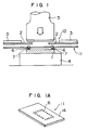
- Fig. 12 is a schematic view showing one example of the TAB type of bonding.
- reference numeral 1 designates a semiconductor chip on which a plurality of bumps 6 are preliminarily formed.
- Numeral 2 designates metallic leads which form a TAB tape 12 together with a tape-like resin film 3.
- the chip 1 is placed on a bonding stage 4 of a TAB bonder with the bumps 6 upside and the TAB tape is placed above the chip 1. In this state, the bonding is carried out in such a manner that a bonding tool 5 having a proper heat is pressed down from the upside in a direction indicated by arrow.
- the TAB tape used in the above method is fabricated by providing sproket holes and a device hole in a film made of a synthetic resin such as polyimide or polyester, laminating a metal foil on the film and thereafter forming a lead pattern by means of a photoresist method.
- the bumps for connection of the TAB tape and electrodes of the semiconductor chip such as IC or LSI are formed in many cases by applying a plating on A1 electrodes of the semiconductor chip, as disclosed by Electronic Parts and Materials, July 1989, p. 71.
- the formation of bumps on the A1 electrodes of IC or LSI through the plating method is high in cost and involves a damage of the semiconductor chip circuit during the bump forming work and hence is not necessarily recommended.
- the conventional TAB system involves the problems that the bump forming method is too expensive, the bump forming work is complicated and there is a possibility of the bump forming work damaging the chip.
- a first object of the present invention in order to solve those problems, is to provide a method of connecting a TAB tape to a semiconductor chip which is simple in work and high in reliability with less probability of the semiconductor chip being damaged.
- a second object of the present invention is to provide materials used in the above-mentioned method of connecting the TAB tape to the semiconductor chip, especially, a bump sheet and a bumped tape.
- a method of connecting a TAB tape to a semiconductor chip comprising the steps of preliminarily locating and fixing ball-like bumps at positions corresponding to a pattern of electrodes of the semiconductor chip to be connected, and bonding the bumps by thermocompression to the electrodes of the semiconductor chip and leads of the TAB tape, respectively, so that each electrode of the semiconductor chip is electrically connected to the corresponding lead of the TAB tape through a corresponding one of the bumps.
- a bump sheet used in a method of connecting a TAB tape to a semiconductor chip comprising a substrate made of a synthetic resin, and ball-like bumps which are made of a metal and are fixed on the substrate at positions corresponding to portions of electrodes of the semiconductor chip to be connected.
- a bumped tape comprising a TAB tape made of a synthetic resin and provided with leads arranged correspondingly to an arrangement of electrodes of a semiconductor chip to which the TAB is to be connected, and bumps made of a metal and fixed to respective end portions of the leads, portion of each bump, which portion is to be connected to one of the electrodes of the semiconductor chip when the lead to which the bump is fixed is connected to the one electrode through the bump, having a shape like a part of spherical ball.
- bumps in the present invention As a material of bumps in the present invention is used a ball-like (or spherical) or massive (or block) electrically conductive material such as gold, aluminum or copper having a uniform particle size or diameter.
- the bumps are preliminarily arranged at positions corresponding to the end portions of leads of a TAB tape and thereafter fixed by a tape-like resin film so that the bump arrangement is not disturbed.
- a resin tape having the bumps arranged at proper positions is called a bump sheet.
- the bump sheet is fabricated by the following method. Polyester, polyimide or the like is suitable as the material of a resin film 14 (see Fig. 1A) in which bumps are to be fixed. Bumps are fixed in a tape-like film preliminarily made of such a resin in a predetermined arrangement.
- a bump sheet can be fabricated in such a manner that bumps are arranged and provisionally fixed on a mold or substrate, a solution of the above-mentioned resin is poured in the mold and solidified to a predetermined thickness and the solidified resin is peeled off together with the bumps from the mold.
- the solution of resin may cover portions of the bumps to be bonded which should be exposed.
- a solvent such as an alkali solution is used to dissolve the resion on surface portions of the bumps, thereby exposing metal surfaces.
- a bump sheet 11 fabricated by the above-mentioned method includes a synthetic resin film 14 having bumps 6 arranged at predetermined positions, as shown in Fig. 1A.
- the bump sheet 11 is inserted in an accurately registered condition between a semiconductor chip 1 placed on a bonding stage 4 and lead portions 2 of a TAB tape 12.
- thermocompression bonding by a bonding tool 5
- electrodes 7 of the semiconductor chip 1 and the leads 2 are bonded to each other through the bumps 6 fixed on the bump sheet 11.
- a heating temperature in the thermocompression bonding is 350°C to 550°C and a pressure thereof is 10 to 50 g/lead.
- the existing TAB bonder can be used as it is.
- the bonding between the leads and the bumps and the bonding between the bumps and the semiconductor chip are carried out en bloc.
- the connection of the leads and the bumps and the connection of the bumps and the semiconductor chip may be carried out separately or in two steps. Namely, the bumps and the leads are first bonded with the TAB tape and the bump sheet being superposed in registration with each other and then the bumps and the electrodes of the semiconductor chip are bonded while positioning them in registration or the order of the above two steps of bonding may be inverted.
- Gold having a purity of 99.99% or more was used to form balls having a mean diameter of 80 ⁇ m, thereby providing bumps.
- the bumps were obtained by cutting a wire of 25 ⁇ m diameter made of a bump forming metal (gold in the shown example) into fragments of a predetermined length and heating the wire fragments upto a temperature higher than a melting point while separating them from each other so as to allow them to take spherical or ball shapes by virtue of the action of surface tension of the metal.
- the length of each wire fragment was selected such that the diameter of its ball-shaped version is 80 ⁇ m.
- the diameters of the actually formed balls falled within a range of 75 to 85 ⁇ m.
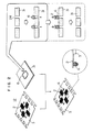
- a bump sheet including such bumps arranged in registration with the positions of inner leads of a 200-pin TAB tape was fabricated by use of a jig as shown in Figs. 3A and 3B. Namely, a thin stainless steel plate 22 formed with through-holes 24 having a diameter of 70 ⁇ m slightly smaller than that of the metal bump ball at positions corresponding to the inner leads of the TAB tape was placed on the upper surface of a vacuum box 21 having a cross section as shown in Fig. 3B and the bumps were distributed on the thin plate 22 while sucking the air in the vacuum box by means of a vacuum pump (not shown) connected to a suction hole 23.
- the bumps were attracted to the positions of the through-holes 24 so that they are provisionally fixed at those positions.
- a solution of polyimide dissolved in a solvent was poured to cover the thin plate 22 and solidified to a form of a bump sheet shown in Fig. 1A.
- the thickness of the polyimide film was 40 ⁇ m. After the polyimide was completely solidified, it was peeled off from the thin plate 22, thereby obtaining a bump sheet which has the bumps fixed at predetermined positions.
- the thus fabricated bump sheet was placed under a 200-pin TAB tape including inner leads having the same arrangement as the bumps in the bump sheet in a registration with each other, and a 200-pin Si chip was placed under the bump sheet.
- the assembly was subjected to a batch thermocompression bonding by use of a TAB bonder the conditions of the thermocompression bonding were 350°C and 2 seconds.
- the pull strength was examined after the bonding. Any one of the pins was cut at the lead portion of the TAB tape. Namely, it was confirmed that the bonding has a sufficient strength.
- Balls having a mean diameter of 90 ⁇ m (87 to 93 ⁇ m in measured values) were produced using gold of 99.99% purity as a raw material. Holes of 80 ⁇ m diameter were preliminarily provided at predetermined positions of a polyethylene sheet of 40 ⁇ m thickness by means of a laser and the gold balls heated to a certain degree were pushed into the holes. The gold balls were fixed at a central portion of the sheet, thereby forming a bump sheet.
- the thus formed bump sheet was bonded by thermocompression to inner leads of a TAB tape and was thereafter bonded again by thermocompression to A1 electrodes of a semiconductor chip.
- the bonding properties of both the bonding portions were satisfactory.
- the TAB tape and the semiconductor chip have been connected by use of the bump sheet.
- a bumped tape in which a TAB tape and a bump sheet are integrated.
- the "transferred bump TAB method” proposed by the National Technical Report, Vol. 31 No. 3 (1985), pp. 116-124 is known as a method of fabricating a bumped tape. This method will now be explained with reference to Fig. 13.
- a TAB tape includes leads 2 formed on a base film 3.
- This TAB tape may be one which is fabricated by a usual method as will be mentioned in later.
- bumps are fixed to the TAB tape as follows. As shown in Fig. 13, an electrically conductive metal 42 is uniformly deposited through an electroless plating method, a sputtering method or the like on a substrate 41 such as a glass plate. Next, a surface of the deposited metal 42 other than portions where bumps are to be formed is masked by an insulator 43. A gold plating is conducted in this state so that gold is deposited on the portions which are not masked by the insulator 43, thereby forming bumps 6. The thus formed bumps 6 are heated and pressed while positioning them in registration with the end portions of leads 2 of the TAB tape so that the bumps are transferred to the end portions of the leads 2.
- the above method it is generally possible to prevent a semiconductor chip from being damaged in the process of formation of bumps. Further, it is said that there is a merit that the cost for fabrication of a bumped tape is low since the bump forming substrate can be used repeatedly. In this method, however, the bump forming work itself is complicated, as is apparent from the process steps shown in Fig. 13. Also, since the bump forming substrate is damaged more and more progressively with the repeated use thereof, careful management of the substrate is required in order to always form satisfactory bumps.
- the bumps are once subjected to deformation when they are transferred from the bump forming substrate to the leads and the deformed bump portions are necessarily bonded to the semiconductor chip, it involves a problem that the bonding is made with less reliability and/or less stability.
- the bumps are formed by plating, there is a great restriction in that the composition and shape of the bump cannot be selected freely.
- an alloy added with a special element is superior to pure gold in many cases where the property of bonding between the pads or electrodes of a semiconductor chip and the bumps is especially important, it is not possible to form such special-alloy bumps by the conventional method using the plating technique.
- the two-layer tape is one in which a metal (copper in many cases) is plated on a film base of the tape, so as to form a lead pattern directly.
- the three-layer tape is one in which a metal foil is covered on a film base through an adhesive and a lead pattern is thereafter formed by etching.
- a synthetic resin such as polyimide or polyester is used as a base film of the TAB tape.
- a product of such a film having sproket holes and a device hole preliminarily formed therein is available as a base film for a TAB tape.
- a bumped tape according to the present invention is fabricated in such a manner that preliminarily prepared ball-like bumps are provisionally arranged on a substrate at positions corresponding to electrodes of a semiconductor chip.
- the substrate and a TAB tape are thereafter superposed in positional registration with each other and then the bumps provisionally arranged on the substrate are transferred to the end portions of leads of the TAB tape. Therefore, portions of the bumps to be bonded to the semiconductor chip are subjected to no deformation so that each bump keeps substantially its original spherical or ball shape. As a result, satisfactory bonding to the semiconductor chip is attainable.
- a TAB tape may be any of an existing two-layer or three-layer TAB tape in which a predetermined pattern of leads 2 is formed on a base film 3.
- a substrate 31 which may be a thin sheet made of stainless steel is prepared for providing an array of bumps. Recesses or through-holes meeting to the sizes of ball like bumps are provided in the substrate 31 at positions corresponding to leads of the TAB tape. By dropping the bumps into the respective recesses or through-holes, the bumps are arranged at predetermined positions.
- the used ball-like bumps are formed in a similar manner to the formation of bumps used for fabrication of a bump sheet as mentioned above. The material and size of the bump are properly selected in accordance with the material components of a TAB tape and a semiconductor chip to be connected.
- the TAB tape and the substrate having the bumps thus arranged at the predetermined positions are superposed one another positional registration with each other such that the bumps of the substrate and the lead end portions of the TAB tape are aligned with each other.
- the bumps are heated and pressed at a temperature of 350 to 550°C under a pressure of 10 to 50 g/lead so that the bumps are transferred to the end portions of the leads.
- a portion of the bump to be bonded to the lead is subjected to deformation due to the pressing but a head portion thereof to be bonded to the electrode of the semiconductor chip is not substantially subjected to deformation or maintains its original soft ball shape. Therefore, satisfactory bonding to the semiconductor chip is attainable.
- the fabricated bumped tape and the semiconductor chip are superposed one another with the bumps and the electrodes of the semiconductor chip being in positional registration with each other and are bonded by a thermocompression bonding method or the like.
- a vacuum box 21 shown in Fig. 3A was attached on a bonding stage of a TAB bonder.
- a thin stainless steel plate 22 of 0.1 mm thickness is detachably mounted on the upper surface of the vacuum box 21 and the interior of the vacuum box 21 is adapted to be pressure-reduced by a vacuum pump (not shown) connected to a suction hole 23.
- the stainless steel plate 22 of 0.1 mm thickness which serves as a bump forming substrate, includes through-holes 24 the number of which is 200 in total, each of which has a diameter of 70 ⁇ m and which are formed by etching at positions in registration with the bump positions of inner leads of a 200-pin TAB tape.
- the cross section of the through-hole was a simple shape as shown in Fig. 4A.
- a multiplicity of balls having a mean diameter of 80 ⁇ m and made of gold having a purity of 99.99% were distributed on an upper surface of the bump forming substrate while pressure-reducing lower part under the substrate.
- ultrasonic oscillation was applied to one end of the substrate so that the gold balls were trapped into the through-holes. Thereafter, excess gold balls remaining on the substrate were readily blown away by air.
- a TAB tape was superposed on the substrate in positional registration with each other and was pressed and heated by means of a bonding tool (not shown), thereby transferring the gold balls arranged on the substrate to the end portions of leads of the TAB tape. It was possible to repeatedly use the substrate, on which gold balls were distributed again.
- the bump transferred to the lead end portion was deformed into a shape having a cross-section as shown in Fig. 5A as the result of the transfer process.
- the tip of the bump maintains its spherical ball shape convenient for bonding to the semiconductor chip.
- a thin stainless steel plate 22 on the upper surface of the vacuum box 21 shown in Fig. 3A was prepared with through-holes, each having a cross section as shown in Fig. 4B.
- Such inclined or tapered through-holes were obtained by laser beam machining.
- the interior of the vacuum box 21 was pressure-reduced so that ball-like bumps dropped into the through-holes in a similar manner to that in the Example 3.
- a TAB tape was superposed on the thin plate or substrate in positional registration with each other and was heated and pressed by means of a bonding tool so that the gold balls arranged on the substrate were transferred to the end portions of leads of the TAB tape.
- the through-hole of the substrate is tapered, there is a possibility that the peeling of the leads to which the bumps have been transferred from the substrate is easy and hence the possibility of the leads being deformed is less.
- the cross section of the bump as transferred is not substantially different from that in the Example 3. Bonding to a semiconductor chip was carried out with a very good result.
- Balls having a diameter of 40 ⁇ m were produced by use of an alloy of low-melting temperature containing 88% of gold and 12% of germanium.
- a vacuum box similar to that in the Example 3 was used and a substrate on the vacuum box was provided with through-holes each having a cross-sectional shape as shown in Fig. 4C.
- the through-hole was produced by forming a concave recess in an upper surface of the substrate by use of a punch having a trigonal pyramid head and thereafter irradiating a bottom portion of the recess with a laser beam.
- the size of the through-hole was determined such that the maximum diameter portion at the upper side of the through-hole was about 30 ⁇ m.
- a thin stainless steel plate 21 on an upper surface of a vacuum box shown in Fig. 3A was formed with through-holes having cross-sectional shapes as shown in Fig. 4B.
- a soft rubber tube was coupled to a suction hole of the vacuum box so as to allow the vacuum box to freely move in a state that the interior of the vacuum box is pressure-reduced.
- a flat plate was prepared. Ball-like gold bumps were randomly distributed on the flat plate.
- the vacuum box was brought in proximity to the gold bumps on the flat plate in a state the vacuum box is turned over with the substrate down side, so that the bumps are attracted to the through-holes as pressure-reduced.
- the vacuum box having the bumps attracted thereto was again turned over and fixed on a bonding stage of a TAB bonder.
- a TAB tape was superposed on the substrate of the vacuum box in positional registration with each other and the bumps were transferred to lead portions of the TAB tape.
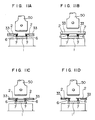
- a bump forming substrate of a double structure having a cross section as shown in Fig. 6A was used.
- An upper substrate 22a made of a stainless steel plate having a thickness of 50 ⁇ m was provided with through-holes of an inner diameter of 100 ⁇ m slightly larger than the diameter 80 ⁇ m of ball-like gold bumps 6 at positions corresponding to a pattern of electrodes of a semiconductor chip.
- a lower substrate 22b made of a stainless steel having a thickness of 200 ⁇ m was provided on its surface with disk-shaped recesses of 10 ⁇ m depth at positions corresponding to the through-holes of the upper substrate.
- the two substrates were superposed with two stainless steel plates or spacers (not shown) of 20 ⁇ m thickness being interposed between the opposite edges of the two substrates so that a gap of about 20 ⁇ m is formed between the two substrates, as shown in Fig. 6A.
- the bumps were distributed on the substrate 22a and ultrasonic oscillation was applied to drop the bumps into the through-holes of the substrate 22a.
- the dropped bumps were supported by the recesses of the lower substrate 22b, as shown in Fig. 6B. But excess bumps, which were not trapped into the through-holes, were left on the substrate 22a. Therefore, a sweeping plate 45 was let run on the upper surface of the substrate 22a to remove the excess bumps, as shown in Fig. 6C.
- the spaces were removed and the substrate 22b was moved upward until the gap between the substrates 22a and 22b disappears.
- the bumps were provisionally positioned regularly with the upper portion of each bump being protruded by about 20 ⁇ m from the upper surface of the substrate 22a, as shown in Fig. 6D.
- Leads of a TAB tape were superposed on the provisionally arranged bumps in positional registration with each other and then the bumps were transferred to the end portions of the leads, in a similar manner to the foreging examples, thereby fabricating a bumped tape.
- the present example since no pressure reduction by a vacuum equipment or the like is not required, the workability is more facilitated. Further, since the substrate to which a pressure is applied by a bonding tool when bonding can be made as thick as possible (200 ⁇ m in the present example), a fabricating equipment having a durability can be provided.
- Balls having a mean diameter of 80 ⁇ m were produced as bumps by use of gold having a purity of 99.99% or more.
- the diameters of the actual balls were within a range of 75 to 85 ⁇ m.
- the gold bumps were arranged at positions meeting the positions of inner leads of a 200-pin TAB tape.
- the arrangement was carried out in a manner as explained below with reference to Figs. 7 and 8A to 8E.
- a mold substrate 22 (see Fig. 7) made of a thin stainless steel plate and formed with through-holes 24 having a diameter of 70 ⁇ m slightly smaller than the diameter of the gold balls at positions corresponding to the inner leads of the TAB tape.
- Fig. 8A shows a cross section taken along line VIII-VIII of Fig. 7.
- the through-holes 24 of the substrate 22 were sucked from the lower side by means of a vacuum pump so that the bumps 6 were attracted to and provisionally fixed at the positions of the through-holes, as shown in Fig. 8B.
- a solution of polyimide dissolved by a solvent was poured and solidified, as shown in Fig. 8C, so that the thickness of the polyimide film 40 after solidification becomes 40 ⁇ m.
- the polyimide was completely solidified, it was peeled off from the mold, thereby obtaining a bump sheet 11, as shown in Fig. 8D, in which the bumps 6 were fixed at predetermined positions.
- a surface of the bump (especially, the upper side thereof) was partially coated with polyimide. Therefore, the surface was lightly etched by means of caustic soda to expose a metal surface of the top portion of the bump.
- a pattern of leads 2 having a thickness of about 30 ⁇ m were formed directly on one surface of the bump sheet by means of copper-plating, as shown in Fig. 8E, thereby completing a bumped tape.
- This bumped tape was placed in positional registration with a semiconductor chip having 200 electrodes in the same arranged as the leads of the TAB tape and the assembly was subjected to thermocompression bonding by a TAB bonder.
- the bonding conditions were such that the temperature is 350°C, the pressure is 30 g/lead ard the time is 2 seconds.
- the pull strength was examined after bonding and it was confirmed that any one of the pins is cut at the inner lead portion of the TAB tape and hence the bonding has a sufficient strength.
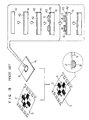
- a usual TAB tape is fabricated such that a portion of the tape where a semiconductor chip is to be located is bored in the form of a window as a device hole and only the end portions of leads extends into inside of the device hole.
- the bonding of the usual TAB tape to the seniconductor chip is carried out, as shown in Fig. 11A.
- reference numeral 2 designates leads, numeral 33 a base film of the TAB tape, numeral 1 the semiconductor chip, numeral 6 bumps, and numeral 50 a bonding tool.
- the bonding is impossible unless the device hole is provided.
- the bonding is carried out, as shown in Fig. 11B.
- a device hole is indispensable to the conventional bumped tape. Therefore, in the case of a two-layer type tape, a device hole is bored by etching a film after leads have been formed. In the case of a three-layer tape, a device hole is preliminarily bored together with sprocket holes by means of punching or the like prior to the formation of leads.
- bumps are provided to extend into a base film. Therefore, as understood from Fig. 11C, even if a tape having no device hole bored therein is used as it is, there is no possibility that a bonding tool of a bonder contacts directly a film. In other words, a step for formation of a device hole can be omitted from a tape fabricating process. This is one additional merit showing that the workability of a method according to the present invention is excellent.
- Balls having a mean diameter of 90 ⁇ m (87 to 93 ⁇ m in measured values) were produced using gold of 99.99% purity as a raw material. 80 ⁇ m holes were bored in a polyimide film of 40 ⁇ m thickness by a laser at positions corresponding to the positions of the electrodes of a 200-pin semiconductor chip. The gold balls were fixed into the holes. The fixing method will now be explained by using Figs. 9 and 10A to 10F.
- a substrate including a pile of a polyimide film 40 formed with holes at positions where the gold balls are to be arranged and a thin stainless steel plate 22 which is placed on the rear side of the film 40 and provided with holes formed at the same positions as those formed in the film 40.
- Fig. 10A shows a cross section taken along line XA-XA of Fig. 9.
- Fig. 10B the rear side of the tin stainless steel plate 22 was evacuated so that the gold balls 6 are attracted to the hole positions of the polyimide film 40.
- the gold balls were mechanically pushed from the front side of the film 40 into the holes of the plate 22 by means of a press 53 so that the head portions of the balls were protruded by about 5 ⁇ m from the opposite surface of the tape.
- a bump sheet as shown in Fig. 10D was obtained in which the gold bump was fixed or positioned asymmetrically with respect to the tape surface.
- this bump sheet or the sheet surface on the side having the bumps protruded by about 5 ⁇ m therefrom was copper-plated to form leads 2 in a predetermined pattern, as shown in Fig. 10E.
- the thickness of the copper plating was in order of 30 ⁇ m.
- the gold bumps and the copper leads were integrated with good electrical conductivity therebetween as well as a mechanical bonding having a certain degree of strength.
- a device hole in the form of window was etched in the tape at a central portion of tle bump sheet for locating there a semiconductor chip to be connected. Thereby, a bumped tape was obtained in which the end portions of the leads were extending inside oi the device hole and the ball-like gold bumps were secured to the end portions of the leads.
- the bumped tape fabricated by the above-mentioned method was used to conduct the test of connection or bonding to a semiconductor chip.
- the thermocompression bonding conditions were such that the pressure was 35 g/lead, the temperature was 450°C and the time was 1 second.
- the pull strengths of the lead bonding portions any one was cut at the lead portion. This shows that the bonding between the leads and the bumps as well as the bonding between the bumps and the semiconductor chip were satisfactory.
- a device hole was formed in a portion of the tape for locating there the semiconductor chip to be connected, like the case of the conventional bumped tape fabricated by the "transferred bump TAB method".
- the bonding can be conducted in a manner as shown in Fig. 11D. Therefore, the heating conditions for bonding can be selected freely, thereby making it possible to realize more satisfactory bonding.
- the bump since the bump has a ball-like shape, there was confirmed a merit that the bumps encounter a very smooth contact with electrode portions of the semiconductor chip upon actual bonding so that no excessive load is imposed upon the chip.
- this bump sheet was fixed by means of an adhesive. Though the head of the bump is slightly protruded, this involved no hindrance to the adhesion of the copper foil.
- This copper foil was etched to form a pattern of leads corresponding to the positions of electrodes of a 100-pin semiconductor chip. Thereafter, the base film was etched to form a device hole, thereby fabricating a bumped tape.
Landscapes
- Engineering & Computer Science (AREA)
- Computer Hardware Design (AREA)
- Microelectronics & Electronic Packaging (AREA)
- Power Engineering (AREA)
- Manufacturing & Machinery (AREA)
- Physics & Mathematics (AREA)
- Condensed Matter Physics & Semiconductors (AREA)
- General Physics & Mathematics (AREA)
- Ceramic Engineering (AREA)
- Wire Bonding (AREA)
Priority Applications (2)
| Application Number | Priority Date | Filing Date | Title |
|---|---|---|---|
| EP98118162A EP0911873A3 (de) | 1989-09-11 | 1990-09-07 | Ein Höckerband und Höckerfilm die angewendet werden zum Verbinden eines TAB-Bandes an einem Halbleiterchip |
| EP92112860A EP0527387B1 (de) | 1989-09-11 | 1990-09-07 | Verfahrungen und Vorrichtung zur Befestigung von Kontakthöckern auf TAB-Trägerleiter |
Applications Claiming Priority (6)
| Application Number | Priority Date | Filing Date | Title |
|---|---|---|---|
| JP234917/89 | 1989-09-11 | ||
| JP234916/89 | 1989-09-11 | ||
| JP23491789 | 1989-09-11 | ||
| JP1234916A JP2780376B2 (ja) | 1989-09-11 | 1989-09-11 | バンプ付きtabテープの製造方法 |
| JP1234915A JP2780375B2 (ja) | 1989-09-11 | 1989-09-11 | Tabテープと半導体チップを接続する方法およびそれに用いるバンプシート |
| JP234915/89 | 1989-09-11 |
Related Child Applications (3)
| Application Number | Title | Priority Date | Filing Date |
|---|---|---|---|
| EP92112860A Division EP0527387B1 (de) | 1989-09-11 | 1990-09-07 | Verfahrungen und Vorrichtung zur Befestigung von Kontakthöckern auf TAB-Trägerleiter |
| EP98118162A Division EP0911873A3 (de) | 1989-09-11 | 1990-09-07 | Ein Höckerband und Höckerfilm die angewendet werden zum Verbinden eines TAB-Bandes an einem Halbleiterchip |
| EP92112860.9 Division-Into | 1990-09-07 |
Publications (3)
| Publication Number | Publication Date |
|---|---|
| EP0427384A2 true EP0427384A2 (de) | 1991-05-15 |
| EP0427384A3 EP0427384A3 (en) | 1992-01-02 |
| EP0427384B1 EP0427384B1 (de) | 1999-04-28 |
Family
ID=27332202
Family Applications (3)
| Application Number | Title | Priority Date | Filing Date |
|---|---|---|---|
| EP98118162A Withdrawn EP0911873A3 (de) | 1989-09-11 | 1990-09-07 | Ein Höckerband und Höckerfilm die angewendet werden zum Verbinden eines TAB-Bandes an einem Halbleiterchip |
| EP92112860A Expired - Lifetime EP0527387B1 (de) | 1989-09-11 | 1990-09-07 | Verfahrungen und Vorrichtung zur Befestigung von Kontakthöckern auf TAB-Trägerleiter |
| EP90309807A Expired - Lifetime EP0427384B1 (de) | 1989-09-11 | 1990-09-07 | Verfahren zum Verbinden eines TAB-Bandes an einem Halbleiterchip |
Family Applications Before (2)
| Application Number | Title | Priority Date | Filing Date |
|---|---|---|---|
| EP98118162A Withdrawn EP0911873A3 (de) | 1989-09-11 | 1990-09-07 | Ein Höckerband und Höckerfilm die angewendet werden zum Verbinden eines TAB-Bandes an einem Halbleiterchip |
| EP92112860A Expired - Lifetime EP0527387B1 (de) | 1989-09-11 | 1990-09-07 | Verfahrungen und Vorrichtung zur Befestigung von Kontakthöckern auf TAB-Trägerleiter |
Country Status (6)
| Country | Link |
|---|---|
| US (1) | US5164336A (de) |
| EP (3) | EP0911873A3 (de) |
| KR (1) | KR940004246B1 (de) |
| DE (2) | DE69033078T2 (de) |
| MY (1) | MY106847A (de) |
| SG (1) | SG73389A1 (de) |
Cited By (4)
| Publication number | Priority date | Publication date | Assignee | Title |
|---|---|---|---|---|
| EP0526147A2 (de) * | 1991-07-25 | 1993-02-03 | Nec Corporation | Halbleiteranordnung vom Filmträgertyp und Verfahren zum Herstellen derselben |
| EP0541116A2 (de) * | 1991-11-08 | 1993-05-12 | Matsushita Electric Industrial Co., Ltd. | Verfahren zum Verbinden eines Leiters mit einer Elektrode in einer elektronischen Anordnung |
| US5803339A (en) * | 1995-11-14 | 1998-09-08 | Nippon Steel Corporation | Process and apparatus for forming ball bumps |
| US5899376A (en) * | 1995-07-11 | 1999-05-04 | Nippon Steel Corporation | Transfer of flux onto electrodes and production of bumps on electrodes |
Families Citing this family (17)
| Publication number | Priority date | Publication date | Assignee | Title |
|---|---|---|---|---|
| US5209390A (en) * | 1989-07-03 | 1993-05-11 | General Electric Company | Hermetic package and packaged semiconductor chip having closely spaced leads extending through the package lid |
| US5519332A (en) * | 1991-06-04 | 1996-05-21 | Micron Technology, Inc. | Carrier for testing an unpackaged semiconductor die |
| US5728599A (en) * | 1993-10-28 | 1998-03-17 | Lsi Logic Corporation | Printable superconductive leadframes for semiconductor device assembly |
| US5367435A (en) * | 1993-11-16 | 1994-11-22 | International Business Machines Corporation | Electronic package structure and method of making same |
| CA2135241C (en) * | 1993-12-17 | 1998-08-04 | Mohi Sobhani | Cavity and bump interconnection structure for electronic packages |
| JPH07221105A (ja) * | 1994-01-31 | 1995-08-18 | Fujitsu Ltd | 半導体装置の製造方法及び半導体装置 |
| JP2833996B2 (ja) * | 1994-05-25 | 1998-12-09 | 日本電気株式会社 | フレキシブルフィルム及びこれを有する半導体装置 |
| FR2728392A1 (fr) * | 1994-12-16 | 1996-06-21 | Bull Sa | Procede et support de connexion d'un circuit integre a un autre support par l'intermediaire de boules |
| US6008071A (en) * | 1995-09-20 | 1999-12-28 | Fujitsu Limited | Method of forming solder bumps onto an integrated circuit device |
| FR2748849B1 (fr) * | 1996-05-20 | 1998-06-19 | Commissariat Energie Atomique | Systeme de composants a hybrider et procede d'hybridation autorisant des dilatations thermiques |
| JP3633941B2 (ja) | 1996-08-27 | 2005-03-30 | 新日本製鐵株式会社 | 半導体装置製造方法 |
| JPH10163211A (ja) * | 1996-12-02 | 1998-06-19 | Fujitsu Ltd | バンプ形成用板部材の製造方法及びバンプ形成方法 |
| US5839191A (en) * | 1997-01-24 | 1998-11-24 | Unisys Corporation | Vibrating template method of placing solder balls on the I/O pads of an integrated circuit package |
| US7135397B2 (en) * | 2003-09-10 | 2006-11-14 | Texas Instruments Incorporated | Method and system for packaging ball grid arrays |
| US7404513B2 (en) * | 2004-12-30 | 2008-07-29 | Texas Instruments Incorporated | Wire bonds having pressure-absorbing balls |
| JP2009099905A (ja) * | 2007-10-19 | 2009-05-07 | Rohm Co Ltd | 半導体装置 |
| CN104206036B (zh) * | 2012-04-10 | 2017-05-03 | 松下知识产权经营株式会社 | 电极接合方法、电极接合结构体的制造方法以及电极接合结构体的制造系统 |
Citations (5)
| Publication number | Priority date | Publication date | Assignee | Title |
|---|---|---|---|---|
| US4587395A (en) * | 1982-12-06 | 1986-05-06 | The Welding Institute | Bonding leads to semiconductor devices |
| EP0229850A1 (de) * | 1985-07-16 | 1987-07-29 | Nippon Telegraph and Telephone Corporation | Verbindungskontakte zwischen substraten und verfahren zur herstellung derselben |
| EP0244666A2 (de) * | 1986-04-29 | 1987-11-11 | International Business Machines Corporation | Bandstruktur für automatische Bandmontage, Mehrschichtpackung und universelle Chipverbindung |
| EP0260490A1 (de) * | 1986-08-27 | 1988-03-23 | Kabushiki Kaisha Toshiba | Verbindungsschicht für ein elektronisches Bauelement und Verfahren zum Verbinden eines elektronischen Bauelementes mit einer solchen Schicht |
| EP0413937A2 (de) * | 1989-08-25 | 1991-02-27 | International Business Machines Corporation | Thermokompressionsverbindung für I.C.-Verpackung |
Family Cites Families (8)
| Publication number | Priority date | Publication date | Assignee | Title |
|---|---|---|---|---|
| JPS5718347A (en) * | 1980-07-08 | 1982-01-30 | Citizen Watch Co Ltd | Mounting structure of ic |
| JPS59202643A (ja) * | 1983-04-30 | 1984-11-16 | Sharp Corp | Lsi接続方法 |
| JPS6052045A (ja) * | 1983-08-31 | 1985-03-23 | Matsushita Electric Ind Co Ltd | バンプ電極形成方法 |
| JPS6149432A (ja) * | 1984-08-18 | 1986-03-11 | Matsushita Electric Ind Co Ltd | 半導体装置の製造方法 |
| JP2532464B2 (ja) * | 1987-05-20 | 1996-09-11 | 松下電器産業株式会社 | バンプの転写方法 |
| JPS63291427A (ja) * | 1987-05-23 | 1988-11-29 | Matsushita Electric Works Ltd | バンプ付フィンガ−リ−ド担持体の製法 |
| JPH0795554B2 (ja) * | 1987-09-14 | 1995-10-11 | 株式会社日立製作所 | はんだ球整列装置 |
| JPH01243554A (ja) * | 1988-03-25 | 1989-09-28 | Hitachi Ltd | 半導体装置の製造方法 |
-
1990
- 1990-09-06 KR KR1019900014073A patent/KR940004246B1/ko not_active IP Right Cessation
- 1990-09-06 US US07/578,491 patent/US5164336A/en not_active Expired - Lifetime
- 1990-09-07 SG SG1996005005A patent/SG73389A1/en unknown
- 1990-09-07 EP EP98118162A patent/EP0911873A3/de not_active Withdrawn
- 1990-09-07 DE DE69033078T patent/DE69033078T2/de not_active Expired - Lifetime
- 1990-09-07 DE DE69027448T patent/DE69027448T2/de not_active Expired - Lifetime
- 1990-09-07 EP EP92112860A patent/EP0527387B1/de not_active Expired - Lifetime
- 1990-09-07 EP EP90309807A patent/EP0427384B1/de not_active Expired - Lifetime
- 1990-09-10 MY MYPI90001556A patent/MY106847A/en unknown
Patent Citations (5)
| Publication number | Priority date | Publication date | Assignee | Title |
|---|---|---|---|---|
| US4587395A (en) * | 1982-12-06 | 1986-05-06 | The Welding Institute | Bonding leads to semiconductor devices |
| EP0229850A1 (de) * | 1985-07-16 | 1987-07-29 | Nippon Telegraph and Telephone Corporation | Verbindungskontakte zwischen substraten und verfahren zur herstellung derselben |
| EP0244666A2 (de) * | 1986-04-29 | 1987-11-11 | International Business Machines Corporation | Bandstruktur für automatische Bandmontage, Mehrschichtpackung und universelle Chipverbindung |
| EP0260490A1 (de) * | 1986-08-27 | 1988-03-23 | Kabushiki Kaisha Toshiba | Verbindungsschicht für ein elektronisches Bauelement und Verfahren zum Verbinden eines elektronischen Bauelementes mit einer solchen Schicht |
| EP0413937A2 (de) * | 1989-08-25 | 1991-02-27 | International Business Machines Corporation | Thermokompressionsverbindung für I.C.-Verpackung |
Non-Patent Citations (3)
| Title |
|---|
| * page 335, right column, paragraph 2 - page 336, left column, paragraph 3; figures 7,14 * * |
| IEEE TRANSACTIONS ON COMPONENTS,HYBRIDS,AND MANUFACTURING vol. 10, no. 3, September 1987, NEW YORK US pages 335 - 340; HATADA ET AL: 'New film carrier assembly technology: transferred bump TAB' * |
| PATENT ABSTRACTS OF JAPAN vol. 2, no. 1 (E-001)5 January 1978 & JP-A-52 115 176 ( HITACHI ) 27 September 1977 * |
Cited By (7)
| Publication number | Priority date | Publication date | Assignee | Title |
|---|---|---|---|---|
| EP0526147A2 (de) * | 1991-07-25 | 1993-02-03 | Nec Corporation | Halbleiteranordnung vom Filmträgertyp und Verfahren zum Herstellen derselben |
| EP0526147A3 (en) * | 1991-07-25 | 1993-08-18 | Nec Corporation | Film-carrier type semiconductor device and process for fabricating the same |
| EP0541116A2 (de) * | 1991-11-08 | 1993-05-12 | Matsushita Electric Industrial Co., Ltd. | Verfahren zum Verbinden eines Leiters mit einer Elektrode in einer elektronischen Anordnung |
| EP0541116A3 (en) * | 1991-11-08 | 1993-12-15 | Matsushita Electric Ind Co Ltd | Method for bonding lead with electrode of electronic device |
| US5899376A (en) * | 1995-07-11 | 1999-05-04 | Nippon Steel Corporation | Transfer of flux onto electrodes and production of bumps on electrodes |
| US5803339A (en) * | 1995-11-14 | 1998-09-08 | Nippon Steel Corporation | Process and apparatus for forming ball bumps |
| US5857610A (en) * | 1995-11-14 | 1999-01-12 | Nippon Steel Corporation | Process and apparatus for forming ball bumps |
Also Published As
| Publication number | Publication date |
|---|---|
| DE69027448T2 (de) | 1996-10-10 |
| DE69033078D1 (de) | 1999-06-02 |
| SG73389A1 (en) | 2000-06-20 |
| KR940004246B1 (ko) | 1994-05-19 |
| EP0527387B1 (de) | 1996-06-12 |
| EP0427384B1 (de) | 1999-04-28 |
| EP0911873A3 (de) | 1999-12-15 |
| EP0427384A3 (en) | 1992-01-02 |
| KR910007096A (ko) | 1991-04-30 |
| EP0527387A1 (de) | 1993-02-17 |
| MY106847A (en) | 1995-08-30 |
| DE69033078T2 (de) | 1999-12-23 |
| DE69027448D1 (de) | 1996-07-18 |
| EP0911873A2 (de) | 1999-04-28 |
| US5164336A (en) | 1992-11-17 |
Similar Documents
| Publication | Publication Date | Title |
|---|---|---|
| US5164336A (en) | Method of connecting tab tape to semiconductor chip, and bump sheet and bumped tape used in the method | |
| KR100437436B1 (ko) | 반도체패키지의제조법및반도체패키지 | |
| US6020218A (en) | Method of manufacturing ball grid array semiconductor package | |
| US5920770A (en) | Resin seal semiconductor package and manufacturing method of the same | |
| EP0704895B1 (de) | Verfahren zur Herstellung einer halbleitenden Anordnung und einer Halbleiterscheibe | |
| US6946329B2 (en) | Methods of making and using a floating interposer | |
| US6664138B2 (en) | Method for fabricating a circuit device | |
| EP1022775B1 (de) | Herstellungsverfahren einer Halbleiteranordnung und einer Montage-Struktur | |
| EP0633607A1 (de) | Verfahren zum Befestigen einer optischen Halbleitervorrichtung an einem optischen Substrat | |
| KR20020026854A (ko) | 반도체 장치 제조 방법 | |
| JPS6150339A (ja) | 半導体装置の製造方法 | |
| JPH0350736A (ja) | 半導体チップのバンプ製造方法 | |
| KR100249539B1 (ko) | 반도체 칩 및 그 제조방법 | |
| KR100303354B1 (ko) | 칩 사이즈 패키지 및 그의 제조방법 | |
| JP2001015630A (ja) | Bga型半導体パッケージ及びその製造方法 | |
| JP2780376B2 (ja) | バンプ付きtabテープの製造方法 | |
| JPH04154137A (ja) | フィルムキャリヤーテープの製造方法 | |
| JPH0719800B2 (ja) | バンプ付きtabテープの製造方法 | |
| JP2000091458A (ja) | 半導体装置及びその製造方法 | |
| WO1992011743A2 (en) | An interconnect structure for connecting electronic devices | |
| JPH0992767A (ja) | 複合リードフレームおよび半導体装置 | |
| JPH0685008A (ja) | テープ自動ボンディングのバンプ転写方法 | |
| JPH0362937A (ja) | フィルムキャリヤ型半導体装置の製造方法 | |
| JPH11102993A (ja) | Bga半導体パッケージの製造方法 | |
| JPH0233945A (ja) | フィルムキャリヤーテープの製造方法 |
Legal Events
| Date | Code | Title | Description |
|---|---|---|---|
| PUAI | Public reference made under article 153(3) epc to a published international application that has entered the european phase |
Free format text: ORIGINAL CODE: 0009012 |
|
| AK | Designated contracting states |
Kind code of ref document: A2 Designated state(s): DE FR GB NL |
|
| PUAL | Search report despatched |
Free format text: ORIGINAL CODE: 0009013 |
|
| AK | Designated contracting states |
Kind code of ref document: A3 Designated state(s): DE FR GB NL |
|
| 17P | Request for examination filed |
Effective date: 19920604 |
|
| 17Q | First examination report despatched |
Effective date: 19940617 |
|
| GRAG | Despatch of communication of intention to grant |
Free format text: ORIGINAL CODE: EPIDOS AGRA |
|
| GRAG | Despatch of communication of intention to grant |
Free format text: ORIGINAL CODE: EPIDOS AGRA |
|
| GRAG | Despatch of communication of intention to grant |
Free format text: ORIGINAL CODE: EPIDOS AGRA |
|
| GRAH | Despatch of communication of intention to grant a patent |
Free format text: ORIGINAL CODE: EPIDOS IGRA |
|
| GRAG | Despatch of communication of intention to grant |
Free format text: ORIGINAL CODE: EPIDOS AGRA |
|
| GRAH | Despatch of communication of intention to grant a patent |
Free format text: ORIGINAL CODE: EPIDOS IGRA |
|
| GRAG | Despatch of communication of intention to grant |
Free format text: ORIGINAL CODE: EPIDOS AGRA |
|
| GRAA | (expected) grant |
Free format text: ORIGINAL CODE: 0009210 |
|
| DX | Miscellaneous (deleted) | ||
| RIN1 | Information on inventor provided before grant (corrected) |
Inventor name: OTSUKA,HIROAKI, C/O DAIICHI GIJIUTSU KENKYUSHO Inventor name: TANAHASHI,HIROYUKI, C/O DAIICHI GIJIUTSU KENKYUSH Inventor name: MARUYAMA,TADAKATSU, C/O DAIICHI GIJIUTSU KENKYUSH Inventor name: ONO, YASUHIDE, C/O DAIICHI GIJIUTSU KENKYUSHO |
|
| AK | Designated contracting states |
Kind code of ref document: B1 Designated state(s): DE FR GB NL |
|
| PG25 | Lapsed in a contracting state [announced via postgrant information from national office to epo] |
Ref country code: FR Free format text: LAPSE BECAUSE OF FAILURE TO SUBMIT A TRANSLATION OF THE DESCRIPTION OR TO PAY THE FEE WITHIN THE PRESCRIBED TIME-LIMIT Effective date: 19990428 Ref country code: NL Free format text: LAPSE BECAUSE OF FAILURE TO SUBMIT A TRANSLATION OF THE DESCRIPTION OR TO PAY THE FEE WITHIN THE PRESCRIBED TIME-LIMIT Effective date: 19990428 |
|
| RAP1 | Party data changed (applicant data changed or rights of an application transferred) |
Owner name: NIPPON STEEL CORPORATION |
|
| REF | Corresponds to: |
Ref document number: 69033078 Country of ref document: DE Date of ref document: 19990602 |
|
| EN | Fr: translation not filed | ||
| RIN2 | Information on inventor provided after grant (corrected) |
Free format text: OHNO, YASUHIDE, C/O DAIICHI GIJIUTSU KENKYUSHO * MARUYAMA,TADAKATSU, C/O DAIICHI GIJIUTSU KENKYUSHO * OTSUKA,HIROAKI, C/O DAIICHI GIJIUTSU KENKYUSHO * TANAHASHI,HIROYUKI, C/O DAIICHI GIJIUTSU KENKYUSHO |
|
| PLBE | No opposition filed within time limit |
Free format text: ORIGINAL CODE: 0009261 |
|
| STAA | Information on the status of an ep patent application or granted ep patent |
Free format text: STATUS: NO OPPOSITION FILED WITHIN TIME LIMIT |
|
| 26N | No opposition filed | ||
| REG | Reference to a national code |
Ref country code: GB Ref legal event code: IF02 |
|
| PGFP | Annual fee paid to national office [announced via postgrant information from national office to epo] |
Ref country code: GB Payment date: 20090902 Year of fee payment: 20 |
|
| PGFP | Annual fee paid to national office [announced via postgrant information from national office to epo] |
Ref country code: DE Payment date: 20090903 Year of fee payment: 20 |
|
| REG | Reference to a national code |
Ref country code: GB Ref legal event code: PE20 Expiry date: 20100906 |
|
| PG25 | Lapsed in a contracting state [announced via postgrant information from national office to epo] |
Ref country code: GB Free format text: LAPSE BECAUSE OF EXPIRATION OF PROTECTION Effective date: 20100906 |
|
| PG25 | Lapsed in a contracting state [announced via postgrant information from national office to epo] |
Ref country code: DE Free format text: LAPSE BECAUSE OF EXPIRATION OF PROTECTION Effective date: 20100907 |