EP0390190B1 - Beutelbefüll- und Schliessvorrichtung - Google Patents
Beutelbefüll- und Schliessvorrichtung Download PDFInfo
- Publication number
- EP0390190B1 EP0390190B1 EP90106157A EP90106157A EP0390190B1 EP 0390190 B1 EP0390190 B1 EP 0390190B1 EP 90106157 A EP90106157 A EP 90106157A EP 90106157 A EP90106157 A EP 90106157A EP 0390190 B1 EP0390190 B1 EP 0390190B1
- Authority
- EP
- European Patent Office
- Prior art keywords
- bags
- filling
- bag
- filling station
- station
- Prior art date
- Legal status (The legal status is an assumption and is not a legal conclusion. Google has not performed a legal analysis and makes no representation as to the accuracy of the status listed.)
- Expired - Lifetime
Links
- 238000007789 sealing Methods 0.000 title claims 2
- 238000003892 spreading Methods 0.000 claims abstract description 19
- 239000000463 material Substances 0.000 claims abstract description 9
- 238000003860 storage Methods 0.000 claims description 10
- 238000005429 filling process Methods 0.000 claims description 7
- 230000000717 retained effect Effects 0.000 claims 1
- 238000009825 accumulation Methods 0.000 description 5
- 238000000034 method Methods 0.000 description 5
- 230000000694 effects Effects 0.000 description 2
- 238000004519 manufacturing process Methods 0.000 description 2
- 238000004806 packaging method and process Methods 0.000 description 2
- 239000000853 adhesive Substances 0.000 description 1
- 230000001070 adhesive effect Effects 0.000 description 1
- 238000007664 blowing Methods 0.000 description 1
- 238000010276 construction Methods 0.000 description 1
- 239000000109 continuous material Substances 0.000 description 1
- 238000005520 cutting process Methods 0.000 description 1
- 230000001934 delay Effects 0.000 description 1
- 239000011888 foil Substances 0.000 description 1
- 238000003780 insertion Methods 0.000 description 1
- 230000037431 insertion Effects 0.000 description 1
- 239000005022 packaging material Substances 0.000 description 1
- 238000000926 separation method Methods 0.000 description 1
- 238000011144 upstream manufacturing Methods 0.000 description 1
Images


Classifications
-
- B—PERFORMING OPERATIONS; TRANSPORTING
- B65—CONVEYING; PACKING; STORING; HANDLING THIN OR FILAMENTARY MATERIAL
- B65B—MACHINES, APPARATUS OR DEVICES FOR, OR METHODS OF, PACKAGING ARTICLES OR MATERIALS; UNPACKING
- B65B43/00—Forming, feeding, opening or setting-up containers or receptacles in association with packaging
- B65B43/12—Feeding flexible bags or carton blanks in flat or collapsed state; Feeding flat bags connected to form a series or chain
- B65B43/123—Feeding flat bags connected to form a series or chain
-
- B—PERFORMING OPERATIONS; TRANSPORTING
- B65—CONVEYING; PACKING; STORING; HANDLING THIN OR FILAMENTARY MATERIAL
- B65B—MACHINES, APPARATUS OR DEVICES FOR, OR METHODS OF, PACKAGING ARTICLES OR MATERIALS; UNPACKING
- B65B39/00—Nozzles, funnels or guides for introducing articles or materials into containers or wrappers
- B65B39/007—Guides or funnels for introducing articles into containers or wrappers
-
- B—PERFORMING OPERATIONS; TRANSPORTING
- B65—CONVEYING; PACKING; STORING; HANDLING THIN OR FILAMENTARY MATERIAL
- B65B—MACHINES, APPARATUS OR DEVICES FOR, OR METHODS OF, PACKAGING ARTICLES OR MATERIALS; UNPACKING
- B65B43/00—Forming, feeding, opening or setting-up containers or receptacles in association with packaging
- B65B43/26—Opening or distending bags; Opening, erecting, or setting-up boxes, cartons, or carton blanks
- B65B43/28—Opening or distending bags; Opening, erecting, or setting-up boxes, cartons, or carton blanks by grippers co-operating with fixed supports
-
- B—PERFORMING OPERATIONS; TRANSPORTING
- B65—CONVEYING; PACKING; STORING; HANDLING THIN OR FILAMENTARY MATERIAL
- B65B—MACHINES, APPARATUS OR DEVICES FOR, OR METHODS OF, PACKAGING ARTICLES OR MATERIALS; UNPACKING
- B65B43/00—Forming, feeding, opening or setting-up containers or receptacles in association with packaging
- B65B43/26—Opening or distending bags; Opening, erecting, or setting-up boxes, cartons, or carton blanks
- B65B43/34—Opening or distending bags; Opening, erecting, or setting-up boxes, cartons, or carton blanks by internal pressure
-
- B—PERFORMING OPERATIONS; TRANSPORTING
- B65—CONVEYING; PACKING; STORING; HANDLING THIN OR FILAMENTARY MATERIAL
- B65B—MACHINES, APPARATUS OR DEVICES FOR, OR METHODS OF, PACKAGING ARTICLES OR MATERIALS; UNPACKING
- B65B59/00—Arrangements to enable machines to handle articles of different sizes, to produce packages of different sizes, to vary the contents of packages, to handle different types of packaging material, or to give access for cleaning or maintenance purposes
- B65B59/003—Arrangements to enable adjustments related to the packaging material
-
- B—PERFORMING OPERATIONS; TRANSPORTING
- B65—CONVEYING; PACKING; STORING; HANDLING THIN OR FILAMENTARY MATERIAL
- B65B—MACHINES, APPARATUS OR DEVICES FOR, OR METHODS OF, PACKAGING ARTICLES OR MATERIALS; UNPACKING
- B65B2210/00—Specific aspects of the packaging machine
- B65B2210/02—Plurality of alternative input or output lines or plurality of alternative packaging units on the same packaging line for improving machine flexibility
Definitions
- the invention relates to a bag filling and closing device in which the filling material is inserted into a prefabricated bag in a filling station, with a spreading and holding device for the bags for preparing the bags for the filling process, which the bags are in a position next to the filling station picks up, spreads and transferred to the filling station.
- a bag filling and closing device corresponding to the preamble of claim 1 is known, which comprises a rotatable disc lying in a vertical plane. There are perforations distributed around the circumference on the disk. Tubular holding devices are provided around the openings, which protrude horizontally from a surface of the disk. A section of a tubular packaging material is pushed onto the tubular holding devices from a roll. The section is cut off at one end and sealed. The disc rotates in the manner of a revolver, and in a subsequent station the goods to be packaged are inserted through the corresponding opening into the interior of the tubular holding device.
- bag filling devices are known in which a single bag stack is kept ready in the filling station and the upper bag is inflated or opened by a vacuum suction device.
- a filling mouth designed as a spreading device dips into the opened container, and then the filling material, for example a container of toilet paper, is pushed into the bag.
- These devices are susceptible to faults, since numerous movement elements are accommodated in a very small space in the area of the filling station and interfere with one another in their movement sequence and can therefore often only be moved one after the other. This leads to delays.
- the contents have to be inserted via a ramp into the top of the bag in the stack of bags. This results in numerous accidents (ski jump effect).
- Another disadvantage is that in practice the number of bags to be accommodated in the filling position is limited to approximately 200 bags. This means that a stack of bags has to be replenished frequently, which in turn leads to frequent business interruptions.
- Another known device has an integrated bag manufacturing and packaging system, in which the individual bags are brought into the filling station immediately after completion with the aid of a suction belt conveyor and then opened by blowing in air or suction. This method is also prone to failure. The bags cannot always be opened reliably due to electrostatic or material-related adhesive forces. Feeding in accordance with the report is not always guaranteed.
- the invention has for its object to design a device of the generic type so that it is less prone to failure and enables the filling of bags with high capacity and high efficiency.
- This object is achieved in a device of the type mentioned above in that two spreading and holding devices are mounted side by side on a slide between the filling station and two storage and / or feeding stations for pouches lying on both sides next to it , and that the spreading and holding devices are arranged on the carriage and the latter is movable in such a way that in the end positions of the carriage movement one of the spreading and holding devices alternately in one of the supply and / or supply stations and one of the spreading and holding devices lies in the filling station.
- the bag supply can thus be kept ready in two separate bag stacks outside the filling station, it can comprise a substantially larger number of bags than when it is accommodated directly in the filling station. Sufficient space is available for the process of opening and spreading, so that a reliable mode of operation can be achieved. The so-called ski jump effect does not apply because only the bag to be filled immediately reaches the filling station. Because of the tandem design, in which a bag is picked up at the same time another is filled, enough time is available for both processes so that the process can be considerably accelerated.
- bags that are fed from a roll and individually separated can also be picked up and spread. This can also be done in such a way that the bag filling device is immediately connected upstream of a manufacturing and packaging system for bags.
- the stack of bags can be placed in the storage and supply stations on a base which can be raised and adjusted in the vertical direction, so that the upper bag is always at the same height.
- the bags are preferably held on two parallel, generally vertical bars which engage in two holes on the edge of the bags.
- the bars are bent at the top ends in a flat curve towards the bags. This makes it easier to pull off the respective upper bag, and the bags in the upper area still move slightly against one another in the stack, so that the sticking together is restricted due to electrostatic or other material-related properties.
- Hold-down devices lie against the upper end of the rods, which cooperate with the ends of the rods in a ball and ball socket configuration and are preferably resiliently biased against the rods. This results in a reliable separation of the bags.
- the contents are preferably brought in individual containers on an accumulation conveyor in front of the filling station and pressed into the bags with a slide.
- pouch used in the present context refers to all kinds of pouch-shaped containers, including sacks, bags made of paper or foils and the like.
- the device comprises a filling station 10, to which supply and / or supply stations 12, 14 are assigned on two opposite sides.
- An endless accumulation conveyor 16 moves in front of the filling station 10 and here has a holding position 18, from which the filling material 22 can be inserted into a bag 24 provided by means of a slide 20.
- the example shown is a bag which is open at the bottom and has a handle 26 which is open on the bottom, that is to say relative to the handle 26, during the filling process.
- the device can of course also be used for other bag, sack or bag shapes.
- the bag 24 is held open by two lateral, swiveling expanding jaws 28, 30. After the bag has been filled, it is advanced into a station 32 (FIG. 1), which is only indicated here, in which the bag is closed and welded and then transported away.
- the spreading jaws 28, 30 are preceded by two lateral guides 34, 36, which guide the filling material 22 laterally during the movement from the accumulation conveyor 16 to the spreading jaws 28, 30 and into the bag 24.
- the guides 36, 38 run parallel and open directly into the spreading jaws 28, 30.
- the guides 34, 36 and the expanding jaws 28, 30 are mounted on a carriage 38 which can be pushed back and forth parallel to the accumulation conveyor 16.
- a guide rod 40 and a pneumatic cylinder 42 are provided.
- the carriage 38 also carries further guides 34, 36 and expanding jaws 28, 30 in a position lying in front of the left supply and / or feed station 12 according to FIGS. 1 and 2.
- the expanding jaws 28, 30 are mounted on vertical swivel axes 44, 46, which are guided in slots 48 of the slide 38 which diverge obliquely in the retraction direction.
- a drive mechanism not shown, is provided for advancing and retracting the expanding jaws. This movement is necessary so that the expanding jaws 28, 30 can be advanced from the position shown on the left in FIGS. 1 and 2 into a bag that is kept ready.
- the sliding movement of the carriage 38 and the positions of the two pairs of guide and spreading jaws on the carriage are selected such that they alternate in front of the left supply and / or supply station 12 and the filling station or in front of the filling station and the right supply and supply station 14 stand.
- One bag 24 can thus be filled at the same time, while another bag is picked up in one of the two supply and supply stations 12, 14.
- suction cups 50, 52 and 54, 56 in the two supply and / or supply stations 12, 14, which raise the upper bag wall and allow the expansion jaws to enter.
- Other devices for opening the bags such as air nozzles, can also be provided.
- a linear conveyor 58 can also be provided, which moves the bags into the holding position 18.
- the loading positions of the two conveyors 16, 58 are designated with 60 and 62.
- the filling process can be significantly accelerated. It is not necessary to accommodate the entire mechanics in the smallest space within the filling station 10. The filling material can always be pushed straight into the bag without moving over a ramp. The bag supply to be made available is considerably larger than if the bag stack were immediately accommodated in the filling station.
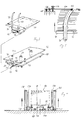
- Figures 3 to 5 illustrate the provision of the bags in the supply and / or supply stations.
- the bags 24 have two holes 74, 76 lying side by side on the bottom edge. These enable a stack of bags to be pushed onto two parallel bars 78, 80, which are vertical in the upper end region and curved in the direction of the bags.
- the rods 78, 80 are connected below the stack of bags by a connecting piece 82 and, moreover, are angled at right angles in the direction of the bags.
- the angled ends which are not labeled, can be inserted into guide grooves 84, 86 at an edge of an overall plate-shaped carriage 88 which has rollers, which are not labeled, for insertion into the stations 12, 14.
- a hook 90 is used to fix the connector 82 and thus the rods 78, 80 on the carriage.
- a rectangular, plate-shaped support 92 is supported, which forms the actual support surface for the stack of bags.
- Support and guide pins 94, 96 determine the minimum distance between the carriage 88 and the support 92.
- Two blind slots 98, 100 entering an edge of the support enable the rods 78, 80 to pass through.
- the carriage 88 has a dovetail guide 102 on the underside, which runs into a corresponding dovetail guide 104 in the stations 12, 14, which is fixedly attached to the floor. This will fix the car.
- the base 92 runs in the stations 12, 14 shown in FIG. 4 with the pins 106, 108 projecting downward onto the top of lifting members 110, 112, which can be raised and lowered with the aid of vertical spindles 114, 116 and guides 118, 120. In this way, the pad 92 can be lifted off the cart and always keep the top surface of the stack of bags at a constant level.
- FIG. 5 shows a partial section of one of the rods 78, the support 92 and the slot 98 in the support 92, which receives the rod 78.
- a stack of bags, not designated, is indicated on the base 92.
- the rod 78 curves in the upper area to the right in FIG. 5, so that the bags can be moved against one another, as can be seen directly in FIG.
- the upper end of the rod 78 forms a ball socket into which a spherical extension 122 engages on the underside of a rod-shaped hold-down 124.
- the hold-down device is pivotably mounted in a horizontal axis 126 and enables the attachment of the attachment 122 against the ball socket to be fixed.
- the hold-down device 124 with the attachment 122 and the ball socket of the rod 78 act as a separating device and prevent an uncontrolled escape of several bags that stick together.
Landscapes
- Engineering & Computer Science (AREA)
- Mechanical Engineering (AREA)
- Supplying Of Containers To The Packaging Station (AREA)
- Basic Packing Technique (AREA)
Description
- Die Erfindung betrifft eine Beutelbefüll- und Schließvorrichtung, bei der das Füllgut in einer Füllstation in einen vorgefertigten Beutel eingeschoben wird, mit einer Aufspreiz- und Halteeinrichtung für die Beutel zur Vorbereitung der Beutel auf den Füllvorgang, die die Beutel in einer neben der Füllstation liegenden Position aufgreift, aufspreizt und in die Füllstation überführt.
- Aus der US-A- 4 495 751 ist eine dem Oberbegriff des Anspruchs 1 entsprechende Beutelbefüll- und Schließvorrichtung bekannt, die eine drehbare, in einer senkrechten Ebene liegende Scheibe umfaßt. Auf der Scheibe befinden sich im Umfang verteilte Durchbrüche. Um die Durchbrüche herum sind rohrförmige Haltevorrichtungen vorgesehen, die von einer Oberfläche der Scheibe waagerecht vorspringen. Auf die rohrförmigen Haltevorrichtungen wird von einer Rolle jeweils ein Abschnitt eines schlauchförmigen Verpackungsmaterials aufgeschoben. Der Abschnitt wird an einem Ende abgetrennt und verschlossen. Die Scheibe dreht sich nach Art eines Revolvers, und in einer nachfolgenden Station wird die zu verpackende Ware durch den entsprechenden Durchbruch hindurch in das Innere der rohrförmigen Haltevorrichtung eingeschoben.
- Weiterhin sind Beutelbefüllvorrichtungen bekannt, bei denen ein Einzelbeutelstapel in der Füllstation bereitgehalten und jeweils der obere Beutel aufgeblasen oder durch Vakuumsauger geöffnet wird. In einer zweiten Bewegung taucht ein als Aufspreizeinrichtung ausgebildeter Füllmund in den geöffneten Behälter ein, und anschließend wird das Füllgut, etwa ein Gebinde Toilettenpapier, in den Beutel eingeschoben. Diese Vorrichtungen sind störanfällig, da im Bereich der Füllstation zahlreiche Bewegungselemente auf engstem Raum untergebracht sind und sich in ihrem Bewegungsablauf gegenseitig behindern und somit vielfach nur nacheinander bewegt werden können. Dies führt zu Verzögerungen. Im übrigen muß das Füllgut über eine Rampe in den jeweils oben liegeden Beutel des Beutelstapels eingeschoben werden. Dadurch ergeben sich zahlreiche Störfälle (Sprungschanzeneffekt). Ein weiterer Nachteil besteht darin, daß in der Praxis die Anzahl der in der Füllposition unterzubringenden Beutel auf ca. 200 Beutel beschränkt ist. Dies erfordert ein häufiges Nachlegen eines Beutelstapels und damit häufige Betriebsunterbrechungen.
- Eine andere bekannte Vorrichtung weist eine integrierte Beutelherstellungs- und -konfektionieranlage auf, bei der die einzelnen Beutel unmittelbar nach der Fertigstellung mit Hilfe eines Saugbandförderers in die Füllstation gebracht und sodann durch Einblasen von Luft oder Ansaugen geöffnet werden. Auch dieses Verfahren ist störanfällig. Die Beutel lassen sich aufgrund elektrostatischer oder materialbedingter Adhäsionskräfte nicht immer zuverlässig öffnen. Die rapportgerechte Zuführung ist nicht immer gewährleistet.
- Daneben sind noch einige Spezialkonstruktionen bekannt, die sich jedoch bisher nicht als zuverlässige und störungsfreie Lösung für Befüllvorgänge aller Art erwiesen haben.
- Der Erfindung liegt die Aufgabe zugrunde, eine Vorrichtung der gattungsgemäßen Art so zu gestalten, daß sie wenig störanfällig ist und das Füllen von Beuteln mit hoher Kapazität und hohem Wirkungsgrad ermöglicht.
- Diese Aufgabe wird erfindungsgemäß bei einer Vorrichtung der eingangs genannten Art dadurch gelöst, daß zwei Aufspreiz- und Halteeinrichtungen nebeneinanderliegend auf einem zwischen der Füllstation und zwei auf beiden Seiten neben dieser liegenden Vorrats- und/oder Zufuhrstationen für Beutel hin- und hergehend beweglichen Schlitten angebracht sind, und daß die Aufspreiz- und Halteeinrichtungen derart auf dem Schlitten angeordnet sind und dieser derart beweglich ist, daß in den Endstellungen der Schlittenbewegung jeweils abwechselnd eine der Aufspreiz- und Halteeinrichtungen in einer der Vorrats- und/oder Zufuhrstationen und eine der Aufspreiz- und Halteeinrichtungen in der Füllstation liegt.
- Da somit der Beutelvorrat außerhalb der Füllstation in zwei getrennten Beutelstapeln bereitgehalten werden kann, kann er eine wesentlich größere Anzahl von Beuteln umfassen als bei der Unterbringung unmittelbar in der Füllstation. Für den Vorgang des Aufziehens und Aufspreizens steht ausreichend Raum zur Verfügung, so daß sich eine zuverlässige Arbeitsweise erreichen läßt. Der sogenannte Sprungschanzeneffekt entfällt, da jeweils nur der unmittelbar zu füllende Beutel in die Füllstation gelangt. Wegen der Tandem-Bauweise, bei der jeweils gleichzeitig ein Beutel aufgegriffen und ein anderer befüllt wird, steht für beide Vorgänge ausreichend Zeit zur Verfügung, so daß das Verfahren erheblich beschleunigt werden kann.
- In den außerhalb der Füllstation liegenden Vorrats- und Zufuhrstationen können auch von einer Rolle zugeführte und einzeln abgetrennte Beutel aufgegriffen und gespreizt werden. Dies kann auch in der Form geschehen, daß der Beutelbefüllvorrichtung unmittelbar eine Herstellungs- und Konfektionieranlage für Beutel vorgeschaltet wird.
- Die Beutelstapel können in den Vorrats- und Zufuhrstationen auf einer Unterlage abgelegt werden, die in senkrechter Richtung anhebbar und nachsteuerbar ist, so daß der obere Beutel stets in der selben Höhe liegt. Die Beutel werden vorzugsweise auf zwei parallelen, insgesamt senkrechten Stangen gehalten, die in zwei Löcher am Rand der Beutel eingreifen. Die Stangen sind an den oberen Enden in einer flachen Kurve in Richtung der Beutel abgebogen. Dadurch wird das Abziehen des jeweils oberen Beutels erleichtert, und die im oberen Bereich liegenden Beutel verschieben sich noch im Stapel leicht gegeneinander, so daß das Zusammenhaften aufgrund elektrostatischer oder anderer materialbedingter Eigenschaften eingeschränkt wird. Gegen das obere Ende der Stangen liegen Niederhalter an, die mit den Enden der Stangen in einer Kugel- und Kugelpfannen-Konfiguration zusammenwirken und vorzugsweise federnd gegen die Stangen vorgespannt sind. Dadurch ergibt sich eine zuverlässige Vereinzelung der Beutel.
- Das Füllgut wird vorzugsweise in einzelnen Gebinden auf einem Stauförderer vor die Füllstation gebracht und mit einem Schieber in die Beutel hineingedrückt.
- Der im vorliegenden Zusammenhang verwendete Begriff der Beutel bezieht sich auf beutelförmige Behälter aller Art, also auch auf Säcke, Tüten aus Papier oder Folien und dergleichen.
- Weitere Merkmale der Erfindung ergeben sich aus den Unteransprüchen.
- Im folgenden werden bevorzugte Ausführungsbeispiele der Erfindung anhand der beigefügten Zeichnung näher erläutert.
- Fig. 1 ist eine schematische Draufsicht auf eine erfindungsgemäße Beutelbefüll- und Schließanlage;
- Fig. 2 ist eine perspektivische Teildarstellung zu Fig. 1;
- Fig. 3 veranschaulicht die Aufnahme der Beutel in der Vorrats- und Zufuhrposition in einer perspektivischen Darstellung;
- Fig. 4 zeigt in einer Frontansicht neben den Elementen der Fig. 3 eine Hubeinrichtung;
- Fig. 5 ist ein Teilschnitt durch einen Beutelstapel in der Vorratsund Zufuhrstation;
- Zur Erläuterung der Beutelbefüll- und Schließvorrichtung in ihrer Gesamtheit soll zunächst auf Figur 1 und 2 Bezug genommen werden. Die Vorrichtung umfaßt als zentralen Bestandteil eine Füllstation 10, der auf zwei gegenüberliegenden Seiten Vorrats- und/oder Zufuhrstationen 12,14 zugeordnet sind. Ein endloser Stauförderer 16 bewegt sich vor der Füllstation 10 entlang und weist hier eine Halteposition 18 auf, von der aus das Füllgut 22 mit Hilfe eines Schiebers 20 in einen bereitgehaltenen Beutel 24 eingeschoben werden kann. Wie insbesondere aus Figur 2 hervorgeht, handelt es sich im dargestellten Beispiel um einen bodenseitig offenen Beutel mit einem Handgriff 26, der während des Füllvorganges am Boden, also gegenüber dem Handgriff 26 offen ist. Die Vorrichtung ist selbstverständlich auch auf andere Beutel-, Sack- oder Tütenformen anwendbar. Während des Füllvorganges wird der Beutel 24 durch zwei seitliche, schwenkbare Spreizbacken 28,30 offengehalten. Nach dem Füllen des Beutels wird dieser in eine hier nur angedeutete Station 32 (Figur 1) vorgerückt, in der der Beutel geschlossen und verschweißt sowie anschließend abtransportiert wird.
- Den Spreizbacken 28,30 sind zwei seitliche Führungen 34,36 vorgelagert, die das Füllgut 22 bei der Bewegung von dem Stauförderer 16 bis zu den Spreizbacken 28,30 und in den Beutel 24 hinein seitlich führen. Die Führungen 36,38 verlaufen parallel und münden unmittelbar in die gespreizten Spreizbacken 28,30 ein. Die Führungen 34,36 und die Spreizbacken 28,30 sind an einem Schlitten 38 gelagert, der parallel zu dem Stauförderer 16 hin- und herverschiebbar ist. Zu diesem Zweck sind, wie Figur 2 andeutet, eine Führungsstange 40 und ein Pneumatikzylinder 42 vorgesehen. Der Schlitten 38 trägt zugleich in einer gemäß Figur 1 und 2 vor der linken Vorrats- und/oder Zufuhrstation 12 liegenden Position weitere Führungen 34,36 und Spreizbacken 28,30. Wie ein Vergleich der beiden Führungs- und Backenpaare zeigt, sind die Spreizbacken 28,30 auf senkrechten Schwenkachsen 44,46 gelagert, die in schräg in Rückzugsrichtung auseinanderlaufenden Schlitzen 48 des Schlittens 38 geführt sind. Zum Vorrücken und Zurückziehen der Spreizbacken ist ein nicht gezeigter Antriebsmechanismus vorgesehen. Diese Bewegung ist erforderlich, damit die Spreizbacken 28,30 aus der links in Figur 1 und 2 gezeigten Position in einen bereitgehaltenen Beutel vorgeschoben werden können.
- Die Verschiebebewegung des Schlittens 38 und die Positionen der beiden Führungs- und Spreizbackenpaare auf dem Schlitten sind so gewählt, daß sie jeweils abwechselnd vor der linken Vorrats- und/oder Zufuhrstation 12 und der Füllstation oder vor der Füllstation und der rechten Vorrats- und Zufuhrstation 14 stehen. Es kann also jeweils gleichzeitig ein Beutel 24 gefüllt werden, während ein weiterer Beutel in einer der beiden Vorrats- und Zufuhrstationen 12,14 aufgegriffen wird.
- Zu diesem Zweck befinden sich in den beiden Vorrats- und/oder Zufuhrstationen 12,14 absenkbare Saugnäpfe 50,52 bzw. 54,56, die die obere Beutelwand anheben und das Eintreten der Spreizbacken ermöglichen. Es können auch andere Einrichtungen zum Aufziehen der Beutel, etwa Luftdüsen, vorgesehen sein.
- Wie Figur 1 zeigt, kann anstelle des Endlos-Stauförderers 16 auch ein Linearförderer 58 vorgesehen sein, der die Beutel bis in die Halteposition 18 bewegt. Mit 60 und 62 sind die Beschickungspositionen der beiden Förderer 16,58 bezeichnet.
- Wegen der Verwendung der von der Füllstation 10 unabhängigen Vorrats- und/oder Zufuhrstationen 12,14 besteht alternativ die Möglichkeit, Beutel für den Füllvorgang zu verwenden, die von einer Rolle als Endlosmaterial zugeführt und einzeln abgetrennt werden. In Figur 1 und 2 sind daher Vorratsrollen 64,66 gezeigt, von denen mit Hilfe von Schneidvorrichtungen 68,70 einzelne Beutel 72 abgeschnitten werden können. Die Beutel werden anschließend mit Hilfe nicht gezeigter Förderer, etwa eines Saugbandförderers, in die Stationen 12,14 bewegt, dort aufgezogen und aufgespreizt, wie es bereits beschrieben wurde.
- Da der Vorgang des Aufziehens und Aufspreizens der Beutel dezentral außerhalb der Füllstation erfolgt und im übrigen zwei getrennte Vorrats- und/oder Zufuhrstationen existieren, kann der Füllvorgang wesentlich beschleunigt werden. Es ist nicht erforderlich, die gesamte Mechanik auf engstem Raum innerhalb der Füllstation 10 unterzubringen. Das Füllgut kann stets ohne Bewegung über eine Rampe geradlinig in die Beutel eingeschoben werden. Der bereitzustellende Beutelvorrat ist wesentlich größer als bei einer unmittelbaren Unterbringung des Beutelstapels in der Füllstation.
- Figuren 3 bis 5 veranschaulichen die Bereitstellung der Beutel in den Vorrats- und/oder Zufuhrstationen. Wie bereits in Figur 1 und 2 andeutungweise zu erkennen war, weisen die Beutel 24 am bodenseitigen Rand zwei nebeneinander liegende Löcher 74,76 auf. Diese ermöglichen, einen Beutelstapel auf zwei insgesamt senkrechte, im oberen Endbereich in Richtung der Beutel gekrümmte, parallele Stangen 78,80 aufzuschieben. Die Stangen 78,80 sind unterhalb des Beutelstapels durch ein Verbindungsstück 82 verbunden und im übrigen in Richtung der Beutel rechtwinklig abgewinkelt. Die nicht bezeichneten, abgewinkelten Enden können in Führungsnuten 84,86 an einem Rand eines ingesamt plattenförmig ausgebildeten Wagens 88 eingeschoben werden, der nicht bezeichnete Rollen zum Einschieben in die Stationen 12,14 aufweist. Ein Haken 90 dient zum Festlegen des Verbindungsstücks 82 und damit der Stangen 78,80 auf dem Wagen.
- Oberhalb des Wagens stützt sich eine rechteckige, plattenförmige Unterlage 92 ab, die die eigentliche Auflagefläche für den Beutelstapel bildet. Stütz- und Führungszapfen 94,96 bestimmen den Mindestabstand zwischen dem Wagen 88 und der Unterlage 92. Zwei in in einen Rand der Unterlage eintretende Sackschlitze 98,100 ermöglichen den Durchgang der Stangen 78,80.
- Wie in Figur 3 angedeutet und auch in Figur 4 erkennbar ist, weist der Wagen 88 an der Unterseite eine Schwalbenschwanzführung 102 auf, die in den Stationen 12,14 in eine entsprechende Schwalbenschwanzführung 104, die ortsfest am Boden angebracht ist, einläuft. Dadurch wird der Wagen festgelegt. Die Unterlage 92 läuft in den in Figur 4 gezeigten Stationen 12,14 mit nach unten ragenden Zapfen 106,108 auf die Oberseite von Hubgliedern 110,112, die mit Hilfe von senkrechten Spindeln 114,116 und Führungen 118,120 angehoben und abgesenkt werden können. Auf diese Weise kann die Unterlage 92 vom Wagen abgehoben werden und die obere Oberfläche des Beutelstapels stets auf konstantem Niveau halten.
- Figur 5 zeigt in einem Teilschnitt eine der Stangen 78, die Unterlage 92 und den Schlitz 98 in der Unterlage 92, der die Stange 78 aufnimmt. Auf der Unterlage 92 ist ein nicht bezeichneter Beutelstapel angedeutet. Die Stange 78 krümmt sich im oberen Bereich nach rechts in Figur 5, so daß die Beutel gegeneinander, wie Figur 2 unmittelbar erkennen läßt, verschoben werden.
- Das obere Ende der Stange 78 bildet eine Kugelpfanne, in die ein kugelförmiger Ansatz 122 an der Unterseite eines stangenförmigen Niederhalters 124 eingreift. Der Niederhalter ist in einer waagerechten Achse 126 schwenkbar gelagert und ermöglicht die Einstellung einer festen Vorspannung des Ansatzes 122 gegen die Kugelpfanne. Der Niederhalter 124 mit den Ansatz 122 und die Kugelpfanne der Stange 78 wirken als Vereinzelungsvorrichtung und verhindern ein unkontrolliertes Austreten mehrerer zusammenhaftender Beutel.
Claims (6)
- Beutelbefüll- und Schließvorrichtung, bei der das Füllgut in einer Füllstation in einen vorgefertigten Beutel eingeschoben wird, mit einer Aufspreiz- und Halteeinrichtung für die Beutel zur Vorbereitung der Beutel auf den Füllvorgang, die die Beutel in einer neben der Füllstation liegenden Position aufgreift, aufspreizt und in die Füllstation überführt, dadurch gekennzeichnet, daß zwei Aufspreiz- und Halteeinrichtungen (28,30,44,46) nebeneinanderliegend auf einem zwischen der Füllstation (10) und zwei auf beiden Seiten neben dieser liegenden Vorrats- und/oder Zufuhrstationen (12,14) für Beutel hin- und hergehend beweglichen Schlitten (38) angebracht sind, und daß die Aufspreiz- und Halteeinrichtungen (28,30,44,46) derart auf dem Schlitten angeordnet sind und dieser derart beweglich ist, daß in den Endstellungen der Schlittenbewegung jeweils abwechselnd eine der Aufspreiz- und Halteeinrichtungen in einer der Vorrats- und/oder Zufuhrstationen (12,14) und eine der Aufspreiz- und Halteeinrichtungen in der Füllstation (10) liegt.
- Vorrichtung nach Anspruch 1, gekennzeichnet durch eine Einrichtung (50,52,54,56) zum Aufziehen der Beutel (24) in jeder der Vorrats- und/oder Zufuhrstationen (12,14).
- Vorrichtung nach Anspruch 1 oder 2, dadurch gekennzeichnet, daß in der Vorrats- und/oder Zufuhrstation (12,14) ein Stapel an einem Rand vorgelochter Einzelbeutel (24) auf zwei parallelen, senkrechten, im oberen Bereich in einer flachen Kurve in Richtung der Beutel gekrümmten Stangen (78,80) gehalten ist, und daß gegen die Enden der Stangen Niederhalter (122,124) elastisch anliegen, die mit den Stangen unter Bildung von korrespondierenden Kugel- und Kugelpfannen-Flächen zusammenwirken.
- Vorrichtung nach einem der Ansprüche 1 bis 3, dadurch gekennzeichnet, daß der Beutelstapel in den Vorrats- und/oder Zufuhrstationen (12,14) auf einer anhebbaren und nachsteuerbaren Unterlage (92) liegt.
- Vorrichtung nach Anspruch 4, dadurch gekennzeichnet, daß die Unterlage (92) senkrecht anhebbar in bezug auf einen Wagen auf diesem angeordnet ist, daß die Stangen (78,80) lösbar mit dem Wagen (88) zu verbinden sind, und daß die Unterlage (92) Schlitze (98,100) zur Aufnahme der Stangen (78,80) aufweist.
- Vorrichtung nach einem der Ansprüche 1 bis 3, dadurch gekennzeichnet, daß den Vorrats- und/oder Zufuhrstationen (12,14) Rollengestelle zur Aufnahme von Rollen (64,66) mit vorgefertigtem Endlos-Beutelmaterial zugeordnet sind.
Priority Applications (1)
| Application Number | Priority Date | Filing Date | Title |
|---|---|---|---|
| AT90106157T ATE83451T1 (de) | 1989-03-30 | 1990-03-30 | Beutelbefuell- und schliessvorrichtung. |
Applications Claiming Priority (2)
| Application Number | Priority Date | Filing Date | Title |
|---|---|---|---|
| DE3910208 | 1989-03-30 | ||
| DE3910208A DE3910208A1 (de) | 1989-03-30 | 1989-03-30 | Beutelbefuell- und schliessvorrichtung |
Publications (2)
| Publication Number | Publication Date |
|---|---|
| EP0390190A1 EP0390190A1 (de) | 1990-10-03 |
| EP0390190B1 true EP0390190B1 (de) | 1992-12-16 |
Family
ID=6377411
Family Applications (1)
| Application Number | Title | Priority Date | Filing Date |
|---|---|---|---|
| EP90106157A Expired - Lifetime EP0390190B1 (de) | 1989-03-30 | 1990-03-30 | Beutelbefüll- und Schliessvorrichtung |
Country Status (4)
| Country | Link |
|---|---|
| US (1) | US5024042A (de) |
| EP (1) | EP0390190B1 (de) |
| AT (1) | ATE83451T1 (de) |
| DE (2) | DE3910208A1 (de) |
Families Citing this family (54)
| Publication number | Priority date | Publication date | Assignee | Title |
|---|---|---|---|---|
| DE4105452C2 (de) * | 1991-02-21 | 1995-07-06 | Icoma Packtechnik Gmbh | Vorrichtung zum Formen von Seitenfaltensäcken oder -beuteln mit Falzboden |
| US5618252A (en) * | 1991-07-26 | 1997-04-08 | Machinery Developments Limited | Packaging apparatus |
| US5265397A (en) * | 1991-12-20 | 1993-11-30 | Eastman Kodak Company | Flexible apparatus and process for loading and sealing pouches |
| US5430990A (en) * | 1992-09-18 | 1995-07-11 | Long John A | Envelope stuffing apparatus |
| US5247780A (en) * | 1993-03-29 | 1993-09-28 | Pitney Bowes Inc. | Rotating envelope opening finger |
| EP0701509B1 (de) * | 1993-05-21 | 1997-04-23 | Longford Equipment International Limited | Vorrichtung zum füllen von briefumschlägen |
| DE4327828A1 (de) * | 1993-08-19 | 1995-03-02 | Schmermund Maschf Alfred | Folieneinschweißeinrichtung |
| US5544466A (en) * | 1994-02-14 | 1996-08-13 | United Parcel Service Of America, Inc. | Method and apparatus for loading and closing a container |
| NL9402112A (nl) * | 1994-12-13 | 1996-07-01 | Huite Wolthuizen | Inrichting voor het per stuk in zakken verpakken van op een transportband aangeleverde producten. |
| NZ272288A (en) * | 1995-06-06 | 1998-09-24 | Minigrip Flexible Packaging Lt | Bag filling method and apparatus for placing article(s) in a bag, chain of preformed bags, each bag supported in a horizontal plane with open mouth, article moved into bag which is then closed |
| NZ329864A (en) | 1998-02-27 | 1998-09-24 | Equipment Technology Ltd | Packaging apparatus with bag fitted over mouth of station where product is ejected horizontally into bag |
| US6779321B1 (en) * | 2000-06-09 | 2004-08-24 | Zellwin Farms Company | Machine and method for bagging elongated produce |
| DE10046852B4 (de) * | 2000-09-22 | 2018-08-23 | Optima Nonwovens Gmbh | Verfahren und Vorrichtung zum Verpacken von Gegenständen in Beutel |
| US6672038B2 (en) * | 2001-03-02 | 2004-01-06 | Optima Machinery Corporation | Bag manipulating method and assembly for a bag filling station |
| US20020121074A1 (en) | 2001-03-02 | 2002-09-05 | Optima Machinery Corporation | Bag loading method and assembly for a bag filling station |
| WO2002096670A1 (en) * | 2001-05-21 | 2002-12-05 | Rodney Ian Rawlinson | A mail insertion method and apparatus |
| DE10140927A1 (de) * | 2001-08-15 | 2003-02-27 | Optima Filling & Packaging | Einrichtung zum Versorgen einer Verpackungsmaschine mit Beuteln |
| JP2004042447A (ja) * | 2002-07-11 | 2004-02-12 | Toyo Jidoki Co Ltd | ストッカー装置付き製袋包装機 |
| US6817518B2 (en) * | 2002-12-06 | 2004-11-16 | First Data Corporation | Systems for preparing presentation instruments for distribution |
| US7344062B2 (en) * | 2002-12-06 | 2008-03-18 | First Data Corporation | Systems for preparing presentation instruments for distribution |
| US8137252B2 (en) * | 2003-05-12 | 2012-03-20 | Ishida Co., Ltd. | Packaging bag supply device and bagging device having the same |
| CA2431281C (en) * | 2003-06-05 | 2006-06-13 | Glen Alvin Jewell | Method of filling bags with granular material |
| EP1786672A2 (de) * | 2004-08-13 | 2007-05-23 | Kencan Australasia Pty Ltd | Verfahren und vorrichtung zur bildung und füllung einer verpackung |
| US7607467B2 (en) * | 2006-01-17 | 2009-10-27 | Cryovac, Inc. | Web dispenser |
| US8938935B2 (en) * | 2006-07-28 | 2015-01-27 | Poly-Clip System Corp. | Two-in-one bagger |
| US8186896B2 (en) * | 2007-07-16 | 2012-05-29 | Cryovac, Inc. | Apparatus and method for printing and dispensing a web |
| AU2008351711A1 (en) * | 2008-02-28 | 2009-09-03 | Uni-Charm Corporation | Pusher used in packaging equipment |
| AU2009222003B2 (en) * | 2008-03-03 | 2014-06-12 | H.W.J. Designs For Agribusiness, Inc. | Bagging assembly |
| WO2010062998A2 (en) * | 2008-11-26 | 2010-06-03 | H.W. J. Designs For Agribusiness, Inc. | Bag retrieval assembly and bag for pressed bales |
| US9156575B2 (en) * | 2011-01-21 | 2015-10-13 | Signode Industrial Grop LLC | Bagging, sealing, and labeling system and method |
| US9845169B2 (en) | 2011-11-01 | 2017-12-19 | Altria Client Services Llc | Apparatus and method of packaging loose product |
| JP6091627B2 (ja) * | 2012-10-03 | 2017-03-08 | アマゾン テクノロジーズ インコーポレイテッド | 材料処理設備において製品を処理するための機能トレイ |
| JP6008684B2 (ja) * | 2012-10-12 | 2016-10-19 | 株式会社三協システム | 包装袋供給装置 |
| CN203428058U (zh) * | 2013-07-18 | 2014-02-12 | 富鼎电子科技(嘉善)有限公司 | 自动装袋机构 |
| US9655303B2 (en) | 2013-09-17 | 2017-05-23 | Signode Industrial Group Llc | Method for containing a bale of compressible material |
| US9944422B2 (en) * | 2014-04-04 | 2018-04-17 | Brady Worldwide, Inc. | Sleeve applicator machine and related method of operation |
| CN104129517B (zh) * | 2014-07-14 | 2016-09-28 | 江阴市业丰科技有限公司 | 注射器自动包装机 |
| US10232968B2 (en) | 2014-10-02 | 2019-03-19 | The Boeing Company | Packaging methods |
| DK178374B1 (en) * | 2014-11-04 | 2016-01-18 | Frank Bruhn Aps | HORIZONTALLY ARRANGED WRAP PACKAGING SYSTEM |
| US10532604B2 (en) * | 2015-02-20 | 2020-01-14 | Dmt Solutions Global Corporation | Pivoting envelope insertion guide |
| US10206333B2 (en) | 2015-05-14 | 2019-02-19 | Signode Industrial Group Llc | Compressed bale packaging apparatus with bag applicator assist device and bag for same |
| US10414528B2 (en) | 2015-05-29 | 2019-09-17 | Graphic Packaging International, Llc | Packaging system |
| ITUB201561098U1 (it) * | 2015-08-06 | 2017-02-06 | Pulsar Srl | Apparecchiatura per il confezionamento di un prodotto in un rispettivo involucro preformato |
| US10370131B2 (en) * | 2015-12-17 | 2019-08-06 | Victor Manuel Quinones | Apparatus and method for packaging coiled materials |
| US20170233119A1 (en) * | 2016-01-04 | 2017-08-17 | Roland Lomerson, Jr. | Quad Wicket Exchange System |
| EP3565761A1 (de) | 2017-01-06 | 2019-11-13 | Kellogg Company | Verpackungsstation und verfahren zum betrieb einer verpackungsstation |
| DK179651B1 (en) | 2017-08-30 | 2019-03-12 | Frank Bruhn Aps | PACKAGING SYSTEM AND METHOD FOR PACKAGING OBJECTS |
| US10569399B1 (en) | 2017-11-03 | 2020-02-25 | Brady Worldwide, Inc. | Wire sleeve hand application tool |
| CN108438341B (zh) * | 2018-04-12 | 2024-07-23 | 广东沃德精密科技股份有限公司 | 静电袋自动上料装置 |
| DK180067B1 (en) | 2019-05-14 | 2020-03-17 | Tentoma A/S | Process for packaging of items and packaging system |
| BR112022015838A2 (pt) | 2020-02-17 | 2022-09-27 | Drylock Tech Nv | Embalagem e método para fabricar uma embalagem para uma pilha de artigos absorventes |
| CN111470100B (zh) * | 2020-03-14 | 2021-09-14 | 上海冀晟自动化成套设备有限公司 | 一种钢桶套膜机组及使用方法 |
| CN114906401B (zh) * | 2021-02-09 | 2023-12-26 | 菜鸟智能物流控股有限公司 | 一种纸箱限位机构、纸箱存储机构和纸箱限位方法 |
| US12503263B1 (en) * | 2022-05-03 | 2025-12-23 | Tension International, Inc. | Horizontal bag packing machine |
Family Cites Families (14)
| Publication number | Priority date | Publication date | Assignee | Title |
|---|---|---|---|---|
| DE1028933B (de) * | 1954-04-20 | 1958-04-24 | Milprint Inc | Haltevorrichtung fuer beutelfoermige Behaelter bei Verpackungsmaschinen |
| US3391519A (en) * | 1965-10-18 | 1968-07-09 | Amsco Packaging Machinery Inc | Bag supporting and retaining means for a packing machine |
| US3556316A (en) * | 1967-03-03 | 1971-01-19 | American Mach & Foundry | Quick-change supply system |
| US3618292A (en) * | 1969-12-10 | 1971-11-09 | Amf Inc | Guide mechanism for packaging machine |
| BE787857A (fr) * | 1971-08-23 | 1973-02-22 | Union Carbide Corp | Appareil a ensacher des produits alimentaires |
| US3731454A (en) * | 1972-02-28 | 1973-05-08 | Ag Pak Inc | Automatic bagging machine |
| US4269016A (en) * | 1978-12-01 | 1981-05-26 | Zupack-Gesellschaft Mbh | Plural line bag forming and filling apparatus |
| US4242854A (en) * | 1979-07-23 | 1981-01-06 | Kimberly-Clark Corporation | Automatic bag loader |
| GB2087338B (en) * | 1980-11-11 | 1984-12-19 | Grace W R & Co | Apparatus and method for wrapping sausage or cheese in a fflexible wrapping material |
| CA1208182A (en) * | 1981-04-28 | 1986-07-22 | Yuji Sawa | Bag packing means featuring an adhesive de-stacking conveyor |
| NZ211252A (en) * | 1984-03-12 | 1986-07-11 | Kureha Chemical Ind Co Ltd | Device for opening bag mouth in automatic bag filling apparatus |
| US4616472A (en) * | 1985-10-10 | 1986-10-14 | W. R. Grace & Co., Cryovac Div. | Method and apparatus for loading side-seal bags |
| JPS63162437A (ja) * | 1986-12-20 | 1988-07-06 | 株式会社エクス | 真空包装装置 |
| DE3715702C2 (de) * | 1987-05-11 | 1998-04-09 | Icoma Fbs Gmbh Packtechnik | Vorrichtung zum Füllen und Verschließen von Seitenfalten aufweisenden Säcken |
-
1989
- 1989-03-30 DE DE3910208A patent/DE3910208A1/de active Granted
-
1990
- 1990-03-30 AT AT90106157T patent/ATE83451T1/de not_active IP Right Cessation
- 1990-03-30 DE DE9090106157T patent/DE59000585D1/de not_active Expired - Fee Related
- 1990-03-30 EP EP90106157A patent/EP0390190B1/de not_active Expired - Lifetime
- 1990-03-30 US US07/501,803 patent/US5024042A/en not_active Expired - Fee Related
Also Published As
| Publication number | Publication date |
|---|---|
| EP0390190A1 (de) | 1990-10-03 |
| DE3910208C2 (de) | 1991-10-10 |
| US5024042A (en) | 1991-06-18 |
| ATE83451T1 (de) | 1993-01-15 |
| DE3910208A1 (de) | 1990-10-04 |
| DE59000585D1 (de) | 1993-01-28 |
Similar Documents
| Publication | Publication Date | Title |
|---|---|---|
| EP0390190B1 (de) | Beutelbefüll- und Schliessvorrichtung | |
| DE3742787C2 (de) | ||
| AT404117B (de) | Einrichtung zum zuführen eines vereinzelten sackes | |
| DE2130591C3 (de) | Vorrichtung zum Verpacken von scheibenförmigen Gegenständen | |
| DE3219267A1 (de) | Automatische verpackungsvorrichtung | |
| DE2817094A1 (de) | Vorrichtung zum zusammenpressen und verpacken von gegenstaenden | |
| DE4203118A1 (de) | Vorrichtung zum ergreifen und transportieren von stapeln flacher gegenstaende | |
| DE3401720A1 (de) | Vorrichtung und verfahren zum palettieren laenglicher, gefuellter beutel | |
| EP0111446B1 (de) | Verfahren zum Abpacken von Schlauchbeuteln in Schachteln, sowie Vorrichtung zur Durchführung des Verfahrens | |
| EP1107865B1 (de) | Vorrichtung zum herstellen und abtransportieren von stapeln aus kunststoffbeuteln, insbesondere automatenbeuteln | |
| DE2154268A1 (de) | Vorrichtung und Verfahren zum Verpacken von Gegenständen | |
| EP4438533A1 (de) | Verfahren und vorrichtung zum ausbilden von verpackungsstapeln | |
| DE3810484A1 (de) | Briefumschlag-paketieranlage | |
| DE3424233A1 (de) | Verfahren und vorrichtung zum befuellen von kartons | |
| CH639629A5 (de) | Vorrichtung zum geordneten ablegen von kreuzspulen. | |
| EP1389597B1 (de) | Verfahren sowie Vorrichtung zum Entstapeln eines aus mehreren horizontal geschichteten Warenlagen bestehenden Warenstapels | |
| AT411990B (de) | Leersackvereinzelung | |
| DE19749825A1 (de) | Vorrichtung zum Öffnen von Kunststoffbeuteln | |
| DE3639494A1 (de) | Verfahren und maschine zur foerderung von offensaecken von einem sackvorrat zu einer sackverschliessvorrichtung | |
| DE2803410A1 (de) | Vorrichtung und verfahren zur handhabung, insbesondere verpackung von gegenstaenden | |
| WO2003089349A1 (de) | Vorrichtung zur abnahme, vereinzelung und öffnung von in magazinen gestapelten säcken | |
| DE19651663C1 (de) | Verfahren und Vorrichtung zum Füllen von Behältern mit Kuverts am Ausgang einer Kuvertiermaschine | |
| DE2522579A1 (de) | Verfahren und vorrichtung zur steuerung der uebergabe eines artikels auf einen von mehreren zufoerderern beschickten sammelfoerderer | |
| EP0916579A1 (de) | Vorrichtung zum Öffnen von Kunststoffbeuteln | |
| DE3904353C2 (de) |
Legal Events
| Date | Code | Title | Description |
|---|---|---|---|
| PUAI | Public reference made under article 153(3) epc to a published international application that has entered the european phase |
Free format text: ORIGINAL CODE: 0009012 |
|
| AK | Designated contracting states |
Kind code of ref document: A1 Designated state(s): AT DE ES FR GB IT SE |
|
| 17P | Request for examination filed |
Effective date: 19901214 |
|
| 17Q | First examination report despatched |
Effective date: 19911011 |
|
| GRAA | (expected) grant |
Free format text: ORIGINAL CODE: 0009210 |
|
| AK | Designated contracting states |
Kind code of ref document: B1 Designated state(s): AT DE ES FR GB IT SE |
|
| PG25 | Lapsed in a contracting state [announced via postgrant information from national office to epo] |
Ref country code: GB Effective date: 19921216 Ref country code: ES Free format text: THE PATENT HAS BEEN ANNULLED BY A DECISION OF A NATIONAL AUTHORITY Effective date: 19921216 |
|
| REF | Corresponds to: |
Ref document number: 83451 Country of ref document: AT Date of ref document: 19930115 Kind code of ref document: T |
|
| ITF | It: translation for a ep patent filed | ||
| REF | Corresponds to: |
Ref document number: 59000585 Country of ref document: DE Date of ref document: 19930128 |
|
| ET | Fr: translation filed | ||
| GBV | Gb: ep patent (uk) treated as always having been void in accordance with gb section 77(7)/1977 [no translation filed] |
Effective date: 19921216 |
|
| PLBE | No opposition filed within time limit |
Free format text: ORIGINAL CODE: 0009261 |
|
| STAA | Information on the status of an ep patent application or granted ep patent |
Free format text: STATUS: NO OPPOSITION FILED WITHIN TIME LIMIT |
|
| PG25 | Lapsed in a contracting state [announced via postgrant information from national office to epo] |
Ref country code: DE Effective date: 19931201 |
|
| 26N | No opposition filed | ||
| EAL | Se: european patent in force in sweden |
Ref document number: 90106157.2 |
|
| ITPR | It: changes in ownership of a european patent |
Owner name: CESSIONE;MEYER JENS |
|
| REG | Reference to a national code |
Ref country code: FR Ref legal event code: TP |
|
| PGFP | Annual fee paid to national office [announced via postgrant information from national office to epo] |
Ref country code: SE Payment date: 19960313 Year of fee payment: 7 |
|
| PGFP | Annual fee paid to national office [announced via postgrant information from national office to epo] |
Ref country code: AT Payment date: 19960327 Year of fee payment: 7 |
|
| PG25 | Lapsed in a contracting state [announced via postgrant information from national office to epo] |
Ref country code: AT Effective date: 19970330 |
|
| PG25 | Lapsed in a contracting state [announced via postgrant information from national office to epo] |
Ref country code: SE Effective date: 19970331 |
|
| EUG | Se: european patent has lapsed |
Ref document number: 90106157.2 |
|
| PGFP | Annual fee paid to national office [announced via postgrant information from national office to epo] |
Ref country code: FR Payment date: 19980316 Year of fee payment: 9 |
|
| PG25 | Lapsed in a contracting state [announced via postgrant information from national office to epo] |
Ref country code: FR Free format text: LAPSE BECAUSE OF NON-PAYMENT OF DUE FEES Effective date: 19991130 |
|
| REG | Reference to a national code |
Ref country code: FR Ref legal event code: ST |
|
| PG25 | Lapsed in a contracting state [announced via postgrant information from national office to epo] |
Ref country code: IT Free format text: LAPSE BECAUSE OF NON-PAYMENT OF DUE FEES;WARNING: LAPSES OF ITALIAN PATENTS WITH EFFECTIVE DATE BEFORE 2007 MAY HAVE OCCURRED AT ANY TIME BEFORE 2007. THE CORRECT EFFECTIVE DATE MAY BE DIFFERENT FROM THE ONE RECORDED. Effective date: 20050330 |