EP0388632B1 - Schreibgerät - Google Patents
Schreibgerät Download PDFInfo
- Publication number
- EP0388632B1 EP0388632B1 EP90102836A EP90102836A EP0388632B1 EP 0388632 B1 EP0388632 B1 EP 0388632B1 EP 90102836 A EP90102836 A EP 90102836A EP 90102836 A EP90102836 A EP 90102836A EP 0388632 B1 EP0388632 B1 EP 0388632B1
- Authority
- EP
- European Patent Office
- Prior art keywords
- insert
- shift
- switching
- writing instrument
- actuating device
- Prior art date
- Legal status (The legal status is an assumption and is not a legal conclusion. Google has not performed a legal analysis and makes no representation as to the accuracy of the status listed.)
- Expired - Lifetime
Links
- 238000006073 displacement reaction Methods 0.000 claims description 3
- 238000002347 injection Methods 0.000 claims description 2
- 239000007924 injection Substances 0.000 claims description 2
- 239000002991 molded plastic Substances 0.000 claims description 2
- 238000010276 construction Methods 0.000 abstract description 3
- 239000004033 plastic Substances 0.000 abstract description 2
- 238000001746 injection moulding Methods 0.000 abstract 1
- 230000000694 effects Effects 0.000 description 2
- 238000003780 insertion Methods 0.000 description 2
- 230000037431 insertion Effects 0.000 description 2
- 230000002093 peripheral effect Effects 0.000 description 2
- 238000005516 engineering process Methods 0.000 description 1
- 238000009434 installation Methods 0.000 description 1
- 230000003993 interaction Effects 0.000 description 1
Images


Classifications
-
- B—PERFORMING OPERATIONS; TRANSPORTING
- B43—WRITING OR DRAWING IMPLEMENTS; BUREAU ACCESSORIES
- B43K—IMPLEMENTS FOR WRITING OR DRAWING
- B43K24/00—Mechanisms for selecting, projecting, retracting or locking writing units
- B43K24/02—Mechanisms for selecting, projecting, retracting or locking writing units for locking a single writing unit in only fully projected or retracted positions
- B43K24/08—Mechanisms for selecting, projecting, retracting or locking writing units for locking a single writing unit in only fully projected or retracted positions operated by push-buttons
- B43K24/084—Mechanisms for selecting, projecting, retracting or locking writing units for locking a single writing unit in only fully projected or retracted positions operated by push-buttons with saw-like or analogous cams
Definitions
- the invention relates to a writing instrument according to the preamble of claim 1.
- Mechanical switching devices for transferring the refill of a ballpoint pen from a retracted position to a writing position are known in many forms. These usually consist of components designed as injection molded plastic parts, which interact when the handle is actuated in a manner determined by the two switch positions, see e.g. BE-A-767025.
- the actuating device is formed in one piece, so that the switching device consists of only two functional elements, namely an actuating device movably arranged inside the shaft of the writing instrument on the one hand and one, fixed within the shaft, i.e. non-displaceably arranged, for example by a split core of a molded switching curve unit (in the case of a two-part shaft) or a shaft opening in the form of the switching curve unit or an insert part on which the switching curve unit is molded, on the other hand.
- a split core of a molded switching curve unit in the case of a two-part shaft
- a shaft opening in the form of the switching curve unit or an insert part on which the switching curve unit is molded on the other hand.
- the actuating device interacts with the insert during the locking or unlocking with an elastically deflectable component, so that the effects of a return spring are simultaneously achieved by its elasticity.
- the actuating device interacts with the insert during the locking or unlocking with an elastically deflectable component, so that the effects of a return spring are simultaneously achieved by its elasticity.
- the design of the actuating device according to the features of claim 2 is structurally simple to implement. According to this, this consists of a receiving device for the mine, a push rod that with the Lever cooperates and a shift rod to which shift teeth are attached, which can be positively engaged with the insert part according to the respective switching position of the handle.
- the pusher, the push rod, the switch rod and the receiving device are preferably designed as a one-piece plastic injection-molded part.
- the features of claim 3 are directed to a first embodiment of the actuating device.
- the features of claim 4 are used to implement clear switching movements of the actuating device.
- the insert is designed according to the features of claim 5 with control cams that cooperate with the switching teeth of the actuating device.
- the control part acts according to the features of claim 6 not only in that the shift teeth of the shift rod are deflected in a defined manner from a rest position, but it also serves to guide the shift rod in a straight line.
- the features of claim 9 are directed to a second embodiment of the actuating device.
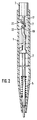
- Fig. 1 in Fig. 1 denotes the barrel or the housing of a ballpoint pen, the refill 2 of which is retracted, i.e. inactive position.
- the mine 2 is received at its end facing the handle 3 in the bore (not shown in more detail) of an actuating device 4 to be described in more detail below, and is stabilized in this position in a known manner by means of a spring 5.
- the spring 5 is supported on the one hand on a collar 6 of the mine 2 and on the other hand on the inner wall of the shaft 1, which is conical at one end.
- the insert 7 which is fixed to the inner wall of the shaft 1, i.e. is attached immovably and will also be described in more detail below.
- the insert part 7 serves to implement two different latching positions of the lead 2, namely their retracted position and their writing position.
- the pusher 3 is in a fixed, preferably non-detachable connection with the actuating device 4.
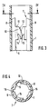
- the insert part 7 consists essentially of two cylindrical, mutually identically formed, shell parts 8 which are arranged opposite one another on the inside of the shaft 1, on each of which a control part 10 is integrally formed, which extends axially parallel to the limiting side 9.
- Each control cam part 10 has on the top side a stop part 11 which extends perpendicularly to the axis of the shaft 1 and peripherally to the inside thereof, to which is connected a curve part 12 which is progressively inclined in the axial direction and which in turn also extends in the peripheral direction.
- the curve part 12 extends to a deepest point 13 and forms an undercut 14 from this, the purpose of which will be explained below.
- an axially parallel groove 15 extends.
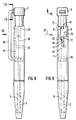
- the actuating device 4 will be described below with reference to FIGS. 5 to 7.
- the one-piece actuating device 4 consists of a push rod 17, which is connected at one end to the handle 3 and at its other end has a cylindrical receiving device 18 for the mine 2, not shown here.
- the pusher 3 and the receiving device 18 are arranged coaxially with one another.
- the push rod 17 and the switching rod 19 extend - starting from the receiving device 18 - in a first section 20 parallel to one another, at the end This section 20, the shift rod 19 has a crank and the section adjoining the crank again runs parallel to the push rod 17.
- This last-mentioned section of the switching rod 19 forms its actual switching section, which will be discussed in the following.
- Numeral 21 denotes a plate part 21 which extends perpendicular to the plane formed by the push rod 17 and the switching rod 19 in the section 20 and which is fastened to the receiving device 18 and is intended for positive engagement with the grooves 16 of the insert part 7. It forms the plate part 21 in connection with the mentioned grooves 16 thus a twist-proof straight execution of the actuating device 4 within the shaft 1.
- the shift rod 19 carries - at its end facing away from the receiving device 18 - a first shift tooth 22 which, like a second shift tooth 23 formed on the shift rod 19 and arranged between the shift tooth 22 and the free end of the shift rod 19, for interaction with the curve part 12 is determined.
- 24 denotes a cuboid component fastened to the push rod 17, a stand which in turn extends perpendicular to the plane of the plate part 21.
- This stand is provided for receiving the shift rod 19 and prevents the shifting tooth 22 from sliding under during the transfer of the mine 2 into the writing position. During the return stroke, ie during the transfer to the rest position, the stand prevents the shift tooth 22 from undercutting 14 can slide back.
- the actuating device 4 In the rest position shown in FIG. 1, the actuating device 4 is thus held in its position by means of the spring 5 and the cam 25, which bears against an edge of the insert part 7. If the pusher 3 is now actuated in the direction of the arrow 26, the switching tooth 22 initially slides on the cam part 12, causing the switching rod 19 to deflect in the direction of the arrow 27, with the switching tooth 22 finally being deepest in the course of this deflection movement Point 13 of the curve part 12 is guided around and snaps elastically into the undercut 14. During the deflection movement of the shift rod 19, the component 24 limiting movements in the drawing plane according to FIG.
- the stop part 11 of the control cam part 10 forms a stop for the push-in movement of the trigger 3, the switching tooth 22 only taking its final position, characterized by a latching with the undercut 14, in which the mine 2 is in the position after the trigger 3 has been relieved 2 is in the write position.
- the switching rod 19 In the writing position, the switching rod 19 is deflected relative to its rest position and is therefore under a pretension, by means of which the position of the switching tooth 22 in the undercut 14 is secured.
- This writing position shown in Fig. 2 is otherwise characterized in that the switching rod 19 is fixed via the undercut 14 in connection with the switching tooth 22 in such a position in which the switching rod 19 is now deflected perpendicularly to the plane of the drawing in FIG. so that the engagement of the switching tooth 22 with the undercut 14 is released due to the pretension of the switching rod 19, the switching tooth 22 jumps into the groove 15 and the actuating device is moved into the rest position according to FIG. 1 under the action of the spring 5.
- the components required for actuating the writing instrument according to the invention merely consist of a movable one, which is formed by the above actuating device and one which is fixedly arranged in the barrel, by the aforementioned Insert formed element exist, so that there is also a quick and easy installation.
- the parts required for the actuation of the writing instrument according to the invention are also characterized by smooth operation and perfect fixing in the respective switching positions.
- the actuating device 4 shows a pusher 3 on which a clip 28 is formed directly. At its end facing the receiving device 18, the handle 3 merges into a radially reduced section 29, to which the push rod 17 is attached directly.
- the section 29 is provided at its end facing the receiving device 18 with two diametrically opposite grooves 30 which are arranged in a plane which extends perpendicular to the plane containing the push rod 17 and the switching rod 19.
- the grooves 30 serve, in a manner still to be explained, for the axial, non-rotatable guidance of the actuating device 4 within the shaft 1.
- 31 is a projection which projects radially from the surface of section 29 and, in a manner to be described later, serves to limit the displacement of the actuating device 4 within the shaft 1.
- Switch arm 19 carries at its end facing the handle 3 a switching tooth 32, which end is in turn deflected out of the plane containing the push rod 17 and most of the switching rod 19.
- the stand which is formed by a cuboid component 24 and is formed on the push rod 17, extends essentially parallel to the plane containing the push rod 17 and the shift rod 19 and is otherwise arranged in accordance with the stand according to the exemplary embodiment of FIGS. 1 to 7.
- An insertion part 7 is in turn arranged within the shaft 1, which in turn consists of two shell parts which are immovably fixed within the shaft 1.
- the insert part 7 also has a control curve part 10, the undercut 14 of which in the writing position of the lead 2 is intended for elastic locking with the switching tooth 32 of the switching rod 19.
- Two guide webs 36 which are diametrically opposite one another within the shaft 1 and are formed on the inside thereof, serve in conjunction with the grooves 30 for the rotationally secure guidance of the actuating device 4 within the shaft.
- Further grooves 37 are arranged in the receiving device 18, namely diametrically opposite one another and in a common one Plane with the above-mentioned grooves 30 of the section 29. The actuating device 4 is thus guided in a rotationally secure manner through the grooves 30 and 37.
- the lead 5 and thus also the actuating device 4 is elastically fixed in position by the spring 5 with the cooperation of the projection 31 and the constriction 34.
- the switching arm 19 and thus the switching tooth 32 are first deflected in the direction of the arrow 27, which deflection movement takes place in the plane of the drawing in FIG. 9 and perpendicular to the plane of the drawing in FIG. 10.
- the switching tooth 32 slides over the control cam part 10 in order to finally engage elastically in the undercut 14 after the trigger 3 has been released.
- the shift rod 19 is now deflected perpendicularly to the drawing planes of FIGS. 9 and 11 to such an extent that the latching of the shift tooth 32 with the undercut 14 is released.
- the mentioned stand prevents the undercut 14 from latching again, so that the shift rod 19 is in its relaxed position and the push button 3 is in the in 8 and 9 return position shown.
- the deflection of the switching rod 19 in the last-mentioned sense is effected by a switching edge 37 which is formed on the insert part 7 and on which the switching tooth 32 slides.
- the actual pusher 3 which is larger in diameter than the section 29 mentioned, and serves as the axial insertion limitation for the actuating device, and when the pusher 3 is pushed in in the opposite direction to the arrow 35 for abutment at the front end of the shaft 1 arrives.
Landscapes
- Mechanical Pencils And Projecting And Retracting Systems Therefor, And Multi-System Writing Instruments (AREA)
- Pens And Brushes (AREA)
- Coating Apparatus (AREA)
Priority Applications (2)
| Application Number | Priority Date | Filing Date | Title |
|---|---|---|---|
| DE9007722U DE9007722U1 (de) | 1989-03-22 | 1990-02-13 | Schreibgerät mit einstückiger Betätigungseinrichtung |
| AT90102836T ATE98164T1 (de) | 1989-03-22 | 1990-02-13 | Schreibgeraet. |
Applications Claiming Priority (2)
| Application Number | Priority Date | Filing Date | Title |
|---|---|---|---|
| DE3909377A DE3909377A1 (de) | 1989-03-22 | 1989-03-22 | Schreibgeraet |
| DE3909377 | 1989-03-22 |
Publications (3)
| Publication Number | Publication Date |
|---|---|
| EP0388632A2 EP0388632A2 (de) | 1990-09-26 |
| EP0388632A3 EP0388632A3 (de) | 1991-05-02 |
| EP0388632B1 true EP0388632B1 (de) | 1993-12-08 |
Family
ID=6376932
Family Applications (1)
| Application Number | Title | Priority Date | Filing Date |
|---|---|---|---|
| EP90102836A Expired - Lifetime EP0388632B1 (de) | 1989-03-22 | 1990-02-13 | Schreibgerät |
Country Status (7)
| Country | Link |
|---|---|
| US (1) | US5145272A (OSRAM) |
| EP (1) | EP0388632B1 (OSRAM) |
| JP (1) | JPH0327989A (OSRAM) |
| KR (1) | KR0120923B1 (OSRAM) |
| AT (1) | ATE98164T1 (OSRAM) |
| DE (2) | DE3909377A1 (OSRAM) |
| ES (1) | ES2047174T3 (OSRAM) |
Cited By (2)
| Publication number | Priority date | Publication date | Assignee | Title |
|---|---|---|---|---|
| WO2002018153A1 (de) | 2000-09-01 | 2002-03-07 | Merz & Krell Gmbh & Co. Kgaa | Schreibgeraet mit einteiliger mechanikkomponente |
| DE10064176C2 (de) * | 2000-09-01 | 2002-11-28 | Merz & Krell Gmbh & Co Kgaa | Schreibgerät mit einteiliger Mechanikkomponente |
Families Citing this family (7)
| Publication number | Priority date | Publication date | Assignee | Title |
|---|---|---|---|---|
| DE29901784U1 (de) * | 1998-11-19 | 2000-03-23 | Hermann Böhler GmbH, 68723 Schwetzingen | Schreibgerät |
| EP1002664A1 (de) | 1998-11-19 | 2000-05-24 | Hermann Böhler Gmbh | Schreibgerät |
| US6742953B2 (en) | 2002-01-24 | 2004-06-01 | Bic Corporation | Writing instrument with display window |
| ES2284771T3 (es) | 2002-12-13 | 2007-11-16 | Societe Bic | Instrumento para escribir, en particular un boligrafo. |
| FR2874533B1 (fr) * | 2004-08-26 | 2006-12-01 | Bic Sa Soc | Instrument d'ecriture comportant un support de cartouche |
| DE202006009893U1 (de) | 2006-06-24 | 2007-11-08 | H & M Gutberlet Gmbh | Kosmetikstift |
| TWI507306B (zh) * | 2012-03-08 | 2015-11-11 | Sdi Corp | A press station with a pushpress function |
Family Cites Families (14)
| Publication number | Priority date | Publication date | Assignee | Title |
|---|---|---|---|---|
| BE466427A (OSRAM) * | 1945-07-05 | |||
| AT201471B (de) * | 1955-05-20 | 1959-01-10 | Alfred Ing Doettlinger | Druckstiftmechanik, insbesondere für Kugelschreiber |
| DE1189889B (de) * | 1958-06-30 | 1965-03-25 | Horst Minkwitz | Druckmechanik fuer Schreibgeraete, insbesondere Kugelschreiber, mit einer Klinke als Verriegelungselement |
| US3070069A (en) * | 1961-07-27 | 1962-12-25 | Joseph L Ruden | Writing implement |
| CH394865A (it) * | 1962-06-07 | 1965-06-30 | Real Patentauswertungs Anstalt | Meccanismo di comando per penne, matite, ecc., a punta scrivente retrattile |
| ES294873A3 (es) * | 1962-12-24 | 1963-10-16 | Termoplastic S R L | Perfeccionamientos en la construcciën de boligrafos |
| DE1284877B (de) * | 1965-08-02 | 1968-12-05 | Bross | Schaltmechanik, insbesondere fuer Kugelschreiber |
| DE1461349A1 (de) * | 1965-08-02 | 1969-05-14 | Bross Dipl Ing Helmut | Druckschaltmechanik,insbesondere fuer Kugelschreiber |
| FR1445378A (fr) * | 1965-08-24 | 1966-07-08 | Dispositif de verrouillage automatique pour avancement et rappel de cartouches de stylos à billes | |
| DE1511334A1 (de) * | 1966-11-23 | 1969-07-31 | H Bross | Druckschalter,insbesondere fuer Kugelschreiber |
| CH482556A (fr) * | 1967-11-14 | 1969-12-15 | Cado Ets | Stylographe à cartouche scripteuse rétractable |
| BE767025A (fr) * | 1971-05-11 | 1971-10-01 | Toffali Giuseppe | Stylo a bille |
| CH597002A5 (OSRAM) * | 1975-10-30 | 1978-03-31 | S Brice L Somers | |
| DE3806221C2 (de) * | 1988-02-26 | 1994-11-24 | Staedtler Fa J S | Schreibgerät mit Druckmechanik |
-
1989
- 1989-03-22 DE DE3909377A patent/DE3909377A1/de active Granted
-
1990
- 1990-02-13 ES ES90102836T patent/ES2047174T3/es not_active Expired - Lifetime
- 1990-02-13 DE DE90102836T patent/DE59003738D1/de not_active Expired - Fee Related
- 1990-02-13 EP EP90102836A patent/EP0388632B1/de not_active Expired - Lifetime
- 1990-02-13 AT AT90102836T patent/ATE98164T1/de not_active IP Right Cessation
- 1990-03-06 JP JP2054779A patent/JPH0327989A/ja active Pending
- 1990-03-22 KR KR1019900003874A patent/KR0120923B1/ko not_active Expired - Fee Related
-
1991
- 1991-08-02 US US07/739,812 patent/US5145272A/en not_active Expired - Lifetime
Cited By (2)
| Publication number | Priority date | Publication date | Assignee | Title |
|---|---|---|---|---|
| WO2002018153A1 (de) | 2000-09-01 | 2002-03-07 | Merz & Krell Gmbh & Co. Kgaa | Schreibgeraet mit einteiliger mechanikkomponente |
| DE10064176C2 (de) * | 2000-09-01 | 2002-11-28 | Merz & Krell Gmbh & Co Kgaa | Schreibgerät mit einteiliger Mechanikkomponente |
Also Published As
| Publication number | Publication date |
|---|---|
| EP0388632A3 (de) | 1991-05-02 |
| KR0120923B1 (ko) | 1997-10-22 |
| ES2047174T3 (es) | 1994-02-16 |
| DE3909377C2 (OSRAM) | 1991-11-14 |
| EP0388632A2 (de) | 1990-09-26 |
| ATE98164T1 (de) | 1993-12-15 |
| DE3909377A1 (de) | 1990-09-27 |
| JPH0327989A (ja) | 1991-02-06 |
| US5145272A (en) | 1992-09-08 |
| KR900014159A (ko) | 1990-10-23 |
| DE59003738D1 (de) | 1994-01-20 |
Similar Documents
| Publication | Publication Date | Title |
|---|---|---|
| EP1869993A2 (de) | Kosmetikstift | |
| EP0388632B1 (de) | Schreibgerät | |
| EP0945304A2 (de) | Verfahren und Vorrichtung zur drehrichtungsgekoppelten Rückstellung eines Schalters | |
| DE1267570B (de) | Schaltmechanik fuer Schreibgeraete | |
| AT2996U1 (de) | Achssicherung für die schwenkachse eines handstempels sowie handstempel | |
| DE3624152C1 (de) | Vorschubmechanik fuer ein Schreibgeraet | |
| DE3046093A1 (de) | Schreibgeraet mit in einer vertiefung des gehaeuses versenkt angeordnetem clip | |
| DE202006009892U1 (de) | Kosmetikprodukt-Austauscheinheit für ein Basis-Stiftmodul eines Kosmetikstifts sowie Set aus einer derartigen Kosmetikprodukt-Austauscheinheit und einer Mehrzahl von Basis-Stiftmodulen | |
| DE102004031586A1 (de) | Spieloptimierte Aufnahme für Schaltstück | |
| DE3510714A1 (de) | Fahrtrichtungsschalter mit selbsttaetiger rueckstellung fuer kraftfahrzeuge | |
| DE2515972A1 (de) | Positions- oder betriebsartanzeiger fuer einen druckschalter | |
| DE3705097A1 (de) | Schreibstift mit schreibmine | |
| DE4229976C2 (de) | Schreibgerät, insbesondere Druckkugelschreiber | |
| DE2807969A1 (de) | Schreibgeraet mit druckmechanik | |
| DE9007722U1 (de) | Schreibgerät mit einstückiger Betätigungseinrichtung | |
| EP1002664A1 (de) | Schreibgerät | |
| DE2722173C2 (de) | Uhr mit einem Druckstellknopf | |
| DE1272172B (de) | Kugelschreiber mit Nachdruck-Schaltmechanik | |
| DE4300754C1 (de) | Schreibgerät, insbes. Druckkugelschreiber | |
| DE3800558C2 (de) | Handschreibgerät | |
| DE1561789C3 (de) | Schreibgerät, insbesondere Kugelschreiber | |
| DE20120684U1 (de) | Schreibgerät, insbesondere Kugelschreiber in einteiliger Ausführung | |
| DE3705098A1 (de) | Schreibstift | |
| DE3621946C2 (OSRAM) | ||
| DE20310572U1 (de) | Minen-Schreibgerät, wie Kugelschreiber, Faserschreiber etc. |
Legal Events
| Date | Code | Title | Description |
|---|---|---|---|
| PUAI | Public reference made under article 153(3) epc to a published international application that has entered the european phase |
Free format text: ORIGINAL CODE: 0009012 |
|
| AK | Designated contracting states |
Kind code of ref document: A2 Designated state(s): AT CH DE ES FR GB IT LI NL SE |
|
| PUAL | Search report despatched |
Free format text: ORIGINAL CODE: 0009013 |
|
| AK | Designated contracting states |
Kind code of ref document: A3 Designated state(s): AT CH DE ES FR GB IT LI NL SE |
|
| 17P | Request for examination filed |
Effective date: 19910405 |
|
| 17Q | First examination report despatched |
Effective date: 19930503 |
|
| GRAA | (expected) grant |
Free format text: ORIGINAL CODE: 0009210 |
|
| AK | Designated contracting states |
Kind code of ref document: B1 Designated state(s): AT CH DE ES FR GB IT LI NL SE |
|
| PG25 | Lapsed in a contracting state [announced via postgrant information from national office to epo] |
Ref country code: SE Effective date: 19931208 |
|
| REF | Corresponds to: |
Ref document number: 98164 Country of ref document: AT Date of ref document: 19931215 Kind code of ref document: T |
|
| GBT | Gb: translation of ep patent filed (gb section 77(6)(a)/1977) |
Effective date: 19931215 |
|
| REF | Corresponds to: |
Ref document number: 59003738 Country of ref document: DE Date of ref document: 19940120 |
|
| ITF | It: translation for a ep patent filed | ||
| REG | Reference to a national code |
Ref country code: ES Ref legal event code: FG2A Ref document number: 2047174 Country of ref document: ES Kind code of ref document: T3 |
|
| PG25 | Lapsed in a contracting state [announced via postgrant information from national office to epo] |
Ref country code: LI Effective date: 19940228 Ref country code: CH Effective date: 19940228 |
|
| ET | Fr: translation filed | ||
| PLBI | Opposition filed |
Free format text: ORIGINAL CODE: 0009260 |
|
| 26 | Opposition filed |
Opponent name: FA. KLIO-ETERNA SCHREIBGERAETE GMBH & CO.KG Effective date: 19940506 |
|
| PLBI | Opposition filed |
Free format text: ORIGINAL CODE: 0009260 |
|
| NLR1 | Nl: opposition has been filed with the epo |
Opponent name: FA. KLIO-ETERNA SCHTEIBGERAETE GMBH & CO.KG |
|
| 26 | Opposition filed |
Opponent name: ROU-BILL GMBH Effective date: 19940831 Opponent name: FA. KLIO-ETERNA SCHREIBGERAETE GMBH & CO.KG Effective date: 19940506 |
|
| REG | Reference to a national code |
Ref country code: CH Ref legal event code: PL |
|
| PG25 | Lapsed in a contracting state [announced via postgrant information from national office to epo] |
Ref country code: DE Effective date: 19941101 |
|
| NLR1 | Nl: opposition has been filed with the epo |
Opponent name: ROU-BILL GMBH. |
|
| RDAH | Patent revoked |
Free format text: ORIGINAL CODE: EPIDOS REVO |
|
| APAE | Appeal reference modified |
Free format text: ORIGINAL CODE: EPIDOS REFNO |
|
| APAC | Appeal dossier modified |
Free format text: ORIGINAL CODE: EPIDOS NOAPO |
|
| APAC | Appeal dossier modified |
Free format text: ORIGINAL CODE: EPIDOS NOAPO |
|
| APAC | Appeal dossier modified |
Free format text: ORIGINAL CODE: EPIDOS NOAPO |
|
| PLBO | Opposition rejected |
Free format text: ORIGINAL CODE: EPIDOS REJO |
|
| PLBN | Opposition rejected |
Free format text: ORIGINAL CODE: 0009273 |
|
| STAA | Information on the status of an ep patent application or granted ep patent |
Free format text: STATUS: OPPOSITION REJECTED |
|
| 27O | Opposition rejected |
Effective date: 20000131 |
|
| NLR2 | Nl: decision of opposition | ||
| REG | Reference to a national code |
Ref country code: GB Ref legal event code: IF02 |
|
| APAH | Appeal reference modified |
Free format text: ORIGINAL CODE: EPIDOSCREFNO |
|
| PGFP | Annual fee paid to national office [announced via postgrant information from national office to epo] |
Ref country code: ES Payment date: 20080221 Year of fee payment: 19 |
|
| PGFP | Annual fee paid to national office [announced via postgrant information from national office to epo] |
Ref country code: GB Payment date: 20080222 Year of fee payment: 19 Ref country code: IT Payment date: 20080227 Year of fee payment: 19 Ref country code: NL Payment date: 20080220 Year of fee payment: 19 |
|
| PGFP | Annual fee paid to national office [announced via postgrant information from national office to epo] |
Ref country code: AT Payment date: 20080222 Year of fee payment: 19 |
|
| PGFP | Annual fee paid to national office [announced via postgrant information from national office to epo] |
Ref country code: FR Payment date: 20080219 Year of fee payment: 19 |
|
| GBPC | Gb: european patent ceased through non-payment of renewal fee |
Effective date: 20090213 |
|
| PG25 | Lapsed in a contracting state [announced via postgrant information from national office to epo] |
Ref country code: AT Free format text: LAPSE BECAUSE OF NON-PAYMENT OF DUE FEES Effective date: 20090213 |
|
| NLV4 | Nl: lapsed or anulled due to non-payment of the annual fee |
Effective date: 20090901 |
|
| REG | Reference to a national code |
Ref country code: FR Ref legal event code: ST Effective date: 20091030 |
|
| PG25 | Lapsed in a contracting state [announced via postgrant information from national office to epo] |
Ref country code: NL Free format text: LAPSE BECAUSE OF NON-PAYMENT OF DUE FEES Effective date: 20090901 |
|
| REG | Reference to a national code |
Ref country code: ES Ref legal event code: FD2A Effective date: 20090214 |
|
| PG25 | Lapsed in a contracting state [announced via postgrant information from national office to epo] |
Ref country code: FR Free format text: LAPSE BECAUSE OF NON-PAYMENT OF DUE FEES Effective date: 20090302 Ref country code: GB Free format text: LAPSE BECAUSE OF NON-PAYMENT OF DUE FEES Effective date: 20090213 |
|
| PG25 | Lapsed in a contracting state [announced via postgrant information from national office to epo] |
Ref country code: ES Free format text: LAPSE BECAUSE OF NON-PAYMENT OF DUE FEES Effective date: 20090214 |
|
| PG25 | Lapsed in a contracting state [announced via postgrant information from national office to epo] |
Ref country code: IT Free format text: LAPSE BECAUSE OF NON-PAYMENT OF DUE FEES Effective date: 20090213 |