EP0363833A1 - Sessel oder Stuhl, insbesondere Bürosessel oder -stuhl - Google Patents
Sessel oder Stuhl, insbesondere Bürosessel oder -stuhl Download PDFInfo
- Publication number
- EP0363833A1 EP0363833A1 EP89118551A EP89118551A EP0363833A1 EP 0363833 A1 EP0363833 A1 EP 0363833A1 EP 89118551 A EP89118551 A EP 89118551A EP 89118551 A EP89118551 A EP 89118551A EP 0363833 A1 EP0363833 A1 EP 0363833A1
- Authority
- EP
- European Patent Office
- Prior art keywords
- mandrel
- seat
- armchair
- support device
- backrest
- Prior art date
- Legal status (The legal status is an assumption and is not a legal conclusion. Google has not performed a legal analysis and makes no representation as to the accuracy of the status listed.)
- Granted
Links
Images

Classifications
-
- A—HUMAN NECESSITIES
- A47—FURNITURE; DOMESTIC ARTICLES OR APPLIANCES; COFFEE MILLS; SPICE MILLS; SUCTION CLEANERS IN GENERAL
- A47C—CHAIRS; SOFAS; BEDS
- A47C1/00—Chairs adapted for special purposes
- A47C1/02—Reclining or easy chairs
- A47C1/022—Reclining or easy chairs having independently-adjustable supporting parts
- A47C1/024—Reclining or easy chairs having independently-adjustable supporting parts the parts, being the back-rest, or the back-rest and seat unit, having adjustable and lockable inclination
- A47C1/0246—Reclining or easy chairs having independently-adjustable supporting parts the parts, being the back-rest, or the back-rest and seat unit, having adjustable and lockable inclination by means of screw-and-nut mechanism
-
- A—HUMAN NECESSITIES
- A47—FURNITURE; DOMESTIC ARTICLES OR APPLIANCES; COFFEE MILLS; SPICE MILLS; SUCTION CLEANERS IN GENERAL
- A47C—CHAIRS; SOFAS; BEDS
- A47C3/00—Chairs characterised by structural features; Chairs or stools with rotatable or vertically-adjustable seats
- A47C3/02—Rocking chairs
- A47C3/025—Rocking chairs with seat, or seat and back-rest unit elastically or pivotally mounted in a rigid base frame
- A47C3/026—Rocking chairs with seat, or seat and back-rest unit elastically or pivotally mounted in a rigid base frame with central column, e.g. rocking office chairs; Tilting chairs
-
- A—HUMAN NECESSITIES
- A47—FURNITURE; DOMESTIC ARTICLES OR APPLIANCES; COFFEE MILLS; SPICE MILLS; SUCTION CLEANERS IN GENERAL
- A47C—CHAIRS; SOFAS; BEDS
- A47C7/00—Parts, details, or accessories of chairs or stools
- A47C7/36—Support for the head or the back
- A47C7/40—Support for the head or the back for the back
- A47C7/44—Support for the head or the back for the back with elastically-mounted back-rest or backrest-seat unit in the base frame
- A47C7/446—Support for the head or the back for the back with elastically-mounted back-rest or backrest-seat unit in the base frame with fluid springs
Definitions
- the invention relates to an armchair or chair, in particular office armchair or chair, in which a support device for a seat and a backrest is rigidly attached to a column provided with a foot, which is arranged with the seat directly on the support device via a between the Seat and the backrest arranged joint and further supported from the support device via intermediate members, the last of which is a console arranged at the lower end of the backrest, in such a way that it can be pivoted backwards against the force of a torsion spring unit and can be locked in various positions, whereby a movement damper is arranged between the support device and a member moving when the backrest is pivoted relative to the support device.
- the invention has for its object to simplify the mechanics of such an armchair or chair known from German utility model 86 25 711.
- this purpose is achieved in such a way that the torsion spring unit is arranged as the joint and the motion damper is used as the only other of the intermediate members mentioned and is articulated at a distance from the torsion spring unit on the support device and on the console and a hydraulic motion damper with lock.
- the invention achieves the full possible advantage in the configuration that the torsion spring unit, although arranged spatially between the seat and the backrest, directly connects the support device to the console.
- the entire mechanism located above the column then forms a unit consisting of only three movably connected parts, the support device, the console and the movement damper.
- the hydraulic movement damper is articulated with its piston rod on the carrying device, preferably in a two-legged bearing block, and it has a mandrel protruding from the piston rod, by means of which the movement damper is unlocked; for this purpose, a device for pressing in the mandrel is arranged under the seat with a hand lever arranged near a side edge of the seat.
- the arrangement of the movement damper provided here already brings the mandrel under a front region of the seat, where the device for pressing in the mandrel does not need to bridge a large distance from the hand that grips in a comfortable position on the side and can be simple.
- this device consists of a shaft provided with the hand lever, on which a cam for pressing in the mandrel is seated and which is preferably also mounted in the two-leg bearing block.
- a leaf spring is arranged between the cam and the mandrel and the cam has a contact surface for the leaf spring such that the leaf spring holds the hand lever in the initial position by pressing on this contact surface, in which the Mandrel has its free end position locking the movement damper, and that the cam has a further, curved contact surface for the leaf spring, with which the cam further tensions the leaf spring and presses the mandrel via the leaf spring into its depressed position in which it unlocks the movement damper.
- the leaf spring has a multiple function. First, it secures the normal locking position. However, it defines the starting position of the rotary lever together with the first-mentioned contact surface of the cam, without, as usual, a stop or the like. would be necessary. Due to their arrangement between the cam and the mandrel, only axial forces act on them; all transverse forces and frictional forces exerted by the cam are absorbed by the spring. The cam can therefore also have a design that would otherwise not be possible.
- the proposed device for pressing in the mandrel is particularly beneficial here, but could also be used to advantage in another mechanism.
- the further arched contact surface mentioned is preferably arched concentrically to the shaft, so that after the mandrel has been pushed in, this is retained even when the hand lever is pivoted further and no clamping is produced. At the same time, however, the push-in position of the mandrel is retained even when the hand lever is released. That means the backrest remains flexible.
- the chair or armchair will be height-adjustable in a manner known per se by means of a gas spring arranged in its column, at the upper end of which a mandrel protrudes, by means of which the gas spring can be unlocked, and a device for pressing in the mandrel under the seat have a hand lever located near a side edge of the seat.
- the entire device serves the task of the invention, since it also consists of two parts in an extremely simple manner, but would otherwise also be usable with advantage.
- the two-armed lever expediently consists of an angled rod which is mounted with one angle leg, preferably in a crank of the supporting device, and whose other angle leg forms the one lever arm, and from a sheet metal plate attached to the former angle leg and covering the mandrel of the gas spring, that forms the other lever arm.
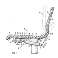
- a support device 2 for a seat 3 and a backrest 4 is rigidly attached to an upper telescopic member 1 of the chair column.
- the carrying device 2 consists of a bent and laterally bent sheet metal plate 6 connected to the telescopic member 1 via a short U-profile 5.
- the U-profile 5 lies with its back 7 (FIG. 2) on the end face of the telescopic member 1 and with the edges its legs on the bottom 8 of the cranking of the sheet metal plate 6.
- a hollow cone 9 is seated in aligned recesses in the back 7 and the bottom 8.
- a gas spring 12 which is supported in the lower telescopic member of the column and which carries everything, projects into the hollow cone 9.
- a bracket 14 of the backrest 4 is connected in an articulated manner to the sheet metal plate 6 by a torsion spring unit 13 of a known type.
- Fig. 4 shows the welded connections on the one hand with the sheet metal plate 6 at 15 and on the other hand with the bracket 14 at 16.
- 4 shows the torque support of the torsion spring unit 13 via a lever 17 against a projection 18 on the sheet metal plate 6; the end of the lever 6 cannot be seen, where a stud screw provided with a screw handle 19 passes through a thread attached to the lever 17 and its end rests on the projection 18.
- the torsion bar 41 itself, as shown in FIGS. 1 and 2, is divided into four; it therefore has a comparatively soft characteristic. Its pretension, which the console 14 tries to pivot upwards and forwards, can be adjusted with the stud screw 20.
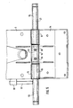
- FIG. 5 further shows the torsion spring unit 13 in detail:
- Two sleeves 51 are welded to the sheet metal plate 6 at 15, a sleeve 52 is welded to the bracket 14 at 16.
- Two tubes 53 and 54 which are in turn aligned, extend through the aligned sleeves 51 and 52. Together with the sleeves 51 and 52, they form a joint as the hinge axis.
- the outer ends of the tubes 53 and 54 are connected to each other by the torsion bar 21.
- the tube 53 is supported on the projection 18 of the sheet metal plate 6 via the lever 17.
- the power transmission takes place from the tube 53 via the torsion bar 21 and the tube 54 to the sleeve 52 welded to the tube 54 at 55 and thus into the bracket 14.
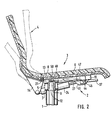
- the force generated by the preload is held by a lockable hydraulic motion damper 24, which is articulated at 22 on the bracket 14 and at 23 on the support device 2.
- the articulated connection with the support device 2 consists in particular of a two-legged bearing block 25 attached to the sheet metal plate 6 , in the two legs not shown stub axles of a head 26 of the piston rod 27 of the hydraulic damper 24 are articulated.
- the connection to the console 14 and, moreover, the structure of the console 14 can be seen in more detail in FIG. 3.
- the console 14 consists of a slightly angled base plate 28 and three projecting console plates 29 welded to it, which are connected to one another by a cross bar 30.
- the crossbar 30 passes through an eyelet 31 of the movement damper 24.
- Shaped plywood panels 32 and 33 are fastened on the sheet metal plate 6 and the base plate 28, which together with cushion pads 34 and 35 form the seat 3 and the backrest 4.
- the torsion spring unit 13 protrudes with its cross-section relatively far above the sheet metal plate 6 and the console 14 upwards and is thus largely between the plywood plates 32 and 33.
- the plywood plate 33 can thus be brought into different angular positions with respect to the plywood plate 32 without being between gives them a gap or nudge, so the seat and backrest act together as a shell.
- the following device is used to adjust the backrest 3 to the rear or to the front:
- a shaft 36 mounted in the two-leg bearing block 25 extends up to close to the side edge of the seat and is provided here with a hand lever 37.
- a cam 38 sits on the shaft 36 between the two legs of the bearing block. It has a flat contact surface 39 and, following this, a contact surface 40 which is curved concentrically to the shaft 36 for a bent leaf spring 41 fastened to the sheet metal plate 6.
- a pivoting of the hand lever from the drawn output position out, in whatever direction, the leaf spring 41 tensions further, ie the hand lever 37 and the cam 38 are held by the leaf spring 41 in the starting position.
- the leaf spring 41 By pivoting the hand lever 37 downward, the leaf spring 41 is pushed back; finally, the curved contact surface 40 bears against the leaf spring 41.
- the leaf spring 41 presses a mandrel 42 protruding from the head 26 of the piston rod 27 into the head 26, whereby the hydraulic movement damper 24 is unlocked and the backrest 4 can be pivoted.
- the height of the seat 3 including the backrest 4 can be adjusted using the following device:
- a shaft 44 provided there with a hand lever 43 extends from the other side edge of the seat to a two-legged bracket 45 in which it is mounted.
- a plate 46 is welded to the shaft 44 between the legs of the bracket 45, whereby two cams forming an extended angle are easily created.
- a rod 47 On the plate 46 is a rod 47 which is mounted with an angled portion 48 in the side walls 10 of the cranking of the plate 6 mentioned.
- a sheet 49 is welded to the section 48 within the crank, which lies on a mandrel 50 protruding from the gas spring 12.
- the plate 46 lifts the rod 47.
- the plate 49 is thus pivoted downward and the mandrel 50 is pressed in by it.
- the gas spring 12 is unlocked and the seat 3 together with the backrest 4 can be moved up and down.
Abstract
Description
- Die Erfindung betrifft einen Sessel oder Stuhl, insbesondere Bürosessel oder -stuhl, bei dem an einer mit einem Fuß versehenen Säule eine Trageinrichtung für einen Sitz und eine Lehne starr befestigt ist, die mit dem, unmittelbar auf der Trageinrichtung angeordneten, Sitz über ein zwischen dem Sitz und der Lehne angeordnetes Gelenk verbunden und ferner von der Trageinrichtung aus über Zwischenglieder, deren letztes eine am unteren Ende der Lehne angeordnete Konsole ist, derart gestützt ist, daß sie gegen die Kraft einer Torsionsfedereinheit nach hinten verschwenkbar und in verschiedenen Stellungen arretierbar ist, wobei zwischen der Trageinrichtung und einem bei Verschwenkung der Lehne sich gegenüber der Trageinrichtung bewegenden Glied ein Bewegungsdämpfer angeordnet ist.
- Der Erfindung liegt die Aufgabe zugrunde, die Mechanik eines solchen, aus dem deutschen Gebrauchsmuster 86 25 711 bekannten, Sessels oder Stuhles vereinfachen.
- Gemäß der Erfindung wird dieser Zweck in der Weise erfüllt, daß die Torsionsfedereinheit als das Gelenk angeordnet ist und der Bewegungsdämpfer als, einziges, weiteres der genannten Zwischenglieder eingesetzt und im Abstand von der Torsionsfedereinheit an der Trageinrichtung sowie an der Konsole angelenkt ist und ein hydraulischer Bewegungsdämpfer mit Verriegelung ist.
- Die Zahl der beweglichen Teile ist damit vermindert.
- Den vollen möglichen Vorteil erreicht die Erfindung aber in der Ausgestaltung, daß die Torsionsfedereinheit, obwohl räumlich zwischen dem Sitz und der Lehne angeordnet, unmittelbar die Trageinrichtung mit der Konsole verbindet.
- Die gesamte über der Säule befindliche Mechanik bildet dann eine Einheit aus nur drei beweglich verbundenen Teilen, der Trageinrichtung, der Konsole und dem Bewegungsdämpfer.
- Nach einer zweckmäßigen Ausgestaltung der Erfindung ist der hydraulische Bewegungsdämpfer mit seiner Kolbenstange an der Trageinrichtung, vorzugsweise in einem zweischenkligen Lagerbock, angelenkt, und er weist einen aus der Kolbenstange herausragenden Dorn auf, durch dessen Eindrücken der Bewegungsdämpfer entriegelt ist; dazu ist unter dem Sitz eine Einrichtung zum Eindrücken des Dornes mit einem nahe einem Seitenrand des Sitzes angeordneten Handhebel angeordnet.
- Die hier vorgesehene Anordnung des Bewegungsdämpfers bringt den Dorn bereits unter einen vorderen Bereich des Sitzes, wo die Einrichtung zum Eindrücken des Dornes von der in einer bequemen Stellung an der Seite zufassenden Hand aus keinen großen Abstand zu überbrücken braucht und einfach ausgeführt sein kann.
- Als besonders einfache und zweckmäßige Ausführung dieser Einrichtung wird vorgeschlagen, daß sie aus einer mit dem Handhebel versehenen Welle besteht, auf der eine Nocke zum Eindrücken des Dornes sitzt und die vorzugsweise ebenfalls in dem zweischenkligen Lagerbock gelagert ist.
- Als besonders vorteilhafte weitere Maßnahme wird dazu vorgeschlagen, daß zwischen der Nocke und dem Dorn eine Blattfeder angeordnet ist und die Nocke eine Anlagefläche für die Blattfeder derart aufweist, daß die Blattfeder durch Druck auf diese Anlagefläche den Handhebel in Ausgangsstellung hält, bei der der Dorn seine den Bewegungsdämpfer verriegelnde, freie Endstellung hat, und daß die Nocke eine weitere, gewölbte Anlagefläche für die Blattfeder aufweist, mit der die Nocke die Blattfeder weiter spannt und den Dorn über die Blattfeder in seine den Bewegungsdämpfer entriegelnde, eingedrückte Stellung drückt.
- Die Blattfeder übt eine Mehrfachfunktion aus. Sie sichert zunächst die normale Verriegelungsstellung. Dabei definiert sie aber gleich zusammen mit der erstgenannten Anlagefläche der Nocke die Ausgangsstellung des Drehhebels, ohne daß dafür, wie gewöhnlich, ein Anschlag o.dgl. nötig wäre. Durch ihre Anordnung zwischen der Nocke und dem Dorn wirken auf diesen nur Axialkräfte ein; alle von der Nocke ausgeübten Querkräfte und Reibungskräfte werden von der Feder aufgenommen. Die Nocke kann deshalb auch eine Gestaltung haben, die sonst nicht möglich wäre.
- Die vorgeschlagene Einrichtung zum Eindrücken des Dornes ist hier besonders förderlich, könnte aber auch an einem anderen Mechanismus mit Vorteil eingesetzt werden.
- Die genannte weitere, gewölbte Anlagefläche ist vorzugsweise konzentrisch zur Welle gewölbt, so daß nach der einmal erreichten Eindrückstellung des Dornes genau diese auch bei weiteren Schwenken des Handhebels erhalten bleibt und nicht etwa eine Klemmung erzeugt wird. Zugleich bleibt damit aber auch bei Loslassen des Handhebels die Eindrückstellung des Dornes erhalten. Daß heißt, die Lehne bleibt beweglich.
- In der Regel wird der Stuhl oder Sessel in an sich bekannter Weise höhenverstellbar sein mittels einer in seiner Säule angeordneten Gasfeder, an deren oberem Ende ein Dorn herausragt, durch dessen Eindrücken die Gasfeder entriegelbar ist, und unter dem Sitz eine Einrichtung zum Eindrücken des Dornes mit einem nahe einem Seitenrand des Sitzes angeordneten Handhebel aufweisen.
- Für diese letztgenannte Einrichtung wird vorgeschlagen, daß sie eine mit dem letztgenannten Handhebel versehene Welle aufweist, auf der zwei einen gestreckten Winkel bildende Nocken sitzen, mittels deren einer ein zweiarmiger Hebel verstellbar ist, durch den der Dorn der Gasfeder eindrückbar ist.
- Die ganze Einrichtung dient der Erfindungsaufgabe, indem sie gleichfalls äußerst einfach aus nur zwei Teilen besteht, wäre aber auch sonst mit Vorteil anwendbar.
- Der zweiarmige Hebel besteht zweckmäßigerweise aus einer gewinkelten Stange, die mit dem einen Winkelschenkel gelagert ist, vorzugsweise in einer Kröpfung der Trageinrichtung, und deren anderer Winkelschenkel den einen Hebelarm bildet, sowie aus einem an dem ersteren Winkelschenkel befestigten, den Dorn der Gasfeder überdeckenden Blech, das den anderen Hebelarm bildet.
- Die Zeichnung gibt ein Ausführungsbeispiel der Erfindung wieder.
- Fig. 1 zeigt einen Bürostuhl in senkrechtem Schnitt, gesehen von der einen Seite,
- Fig. 2 zeigt den Bürostuhl in senkrechtem Schnitt, gesehen von der anderen Seite,
- Fig. 3 zeigt den Bürostuhl in Rückansicht,
- Fig. 4 zeigt den Bürostuhl in Draufsicht und
- Fig. 5 zeigt einen Ausschnitt aus Fig. 4 in größerem Maßstab.
- Auf einem oberen Teleskopglied 1 der Stuhlsäule ist eine Trageinrichtung 2 für einen Sitz 3 und eine Lehne 4 starr befestigt.
- Die Trageinrichtung 2 besteht aus einer über ein kurzes U-Profil 5 mit dem Teleskopglied 1 verbundenen gekröpften und seitlich abgekanteten Blechplatte 6. Das U-Profil 5 liegt mit seinem Rücken 7 (Fig. 2) an der Stirnseite des Teleskopglieds 1 und mit den Kanten seiner Schenkel am Boden 8 der Kröpfung der Blechplatte 6. In fluchteten Ausnehmungen des Rückens 7 und des Bodens 8 sitzt ein Hohlkonus 9. Eine Seitenwand 10 der Kröpfung ist außer in Fig. 2 in Fig. 1 zu erkennen, dort auch eine der beiden Abkantungen 11 der Blechplatte 6. In der Draufsicht nach Fig. 4 erscheinen beide schräge Seitenwände 10 sowie der Boden 8 der Kröpfung. Alles dies ist Schweißkonstruktion.
- In den Hohlkonus 9 ragt mit einem entsprechenden Konus eine im unteren Teleskopglied der Säule abgestützte Gasfeder 12, die alles trägt.
- Durch eine Torsionsfedereinheit 13 bekannter Art ist eine Konsole 14 der Lehne 4 mit der Blechplatte 6 gelenkig verbunden. Fig. 4 läßt die Schweißverbindungen einerseits mit der Blechplatte 6 bei 15 und andererseits mit der Konsole 14 bei 16 erkennen. Ferner zeigt Fig. 4 die Drehmomentabstützung der Torsionsfedereinheit 13 über einen Hebel 17 gegen einen Vorsprung 18 an der Blechplatte 6; nicht zu sehen ist das Ende des Hebels 6, wo eine mit einem Schraubgriff 19 versehene Stiftschraube ein an dem Hebel 17 angebrachtes Gewinde durchsetzt und mit ihrem Ende an dem Vorsprung 18 anliegt. Der Torsionsstab 41 selbst ist, wie Fig. 1 und 2 zeigen, viergeteilt; er hat daher eine vergleichweise weiche Kennlinie. Seine Vorspannung, die die Konsole 14 nach oben und vorne zu schwenken sucht, läßt sich mit der Stiftschraube 20 einstellen.
- In Fig. 5 ist die Torsionsfedereinheit 13 weiter im einzelnen dargestellt:
Zwei Hülsen 51 sind bei 15 mit der Blechplatte 6 verschweißt, eine Hülse 52 ist bei 16 mit der Konsole 14 verschweißt. Durch die fluchtenden Hülsen 51 und 52 hindurch erstrecken sich zwei, wiederum miteinander fluchtende, Rohre 53 und 54. Sie bilden als Gelenkachse zusammen mit den Hülsen 51 und 52 ein Gelenk. - Die äußeren Enden der Rohre 53 und 54 sind durch den Torsionsstab 21 miteinander verbunden. Das Rohr 53 ist über den Hebel 17 an dem Vorsprung 18 der Blechplatte 6 abgestützt. Die Kraftübertragung vollzieht sich von dem Rohr 53 weiter über den Torsionsstab 21 und das Rohr 54 auf die bei 55 mit dem Rohr 54 verschweißte Hülse 52 und somit in die Konsole 14.
- Die durch die Vorspannung erzeugte Kraft wird gehalten durch einen bei 22 an der Konsole 14 und bei 23 an der Trageinrichtung 2 angelenkten, verriegelbaren hydraulischen Bewegungsdämpfer 24. Die gelenkige Verbindung mit der Trageinrichtung 2 besteht im einzelnen aus einem an der Blechplatte 6 befestigten zweischenkligen Lagerbock 25, in dessen beide Schenkel nicht gezeichnete Achsstummel eines Kopfes 26 der Kolbenstange 27 des hydraulischen Bewegungsdämpfers 24 gelenkig gelagert sind. Die Verbindung mit der Konsole 14 und darüberhinaus der Aufbau der Konsole 14 sind in Fig. 3 näher zu erkennen. Die Konsole 14 besteht aus einem leicht gewinkelten Grundblech 28 und drei an diesem angeschweißten abstehenden Konsolblechen 29, die durch eine Querstange 30 miteinander verbunden sind. Die Querstange 30 durchsetzt eine Öse 31 des Bewegungsdämpfers 24.
- Auf der Blechplatte 6 und dem Grundblech 28 sind geformte Sperrholzplatten 32 bzw. 33 befestigt, die zusammen mit Polsterauflagen 34 bzw. 35 den Sitz 3 bzw. die Lehne 4 bilden. Die Torsionsfedereinheit 13 ragt mit ihrem Querschnitt verhältnismäßig weit über die Blechplatte 6 und die Konsole 14 nach oben heraus und liegt so weitgehend zwischen den Sperrholzplatten 32 und 33. Die Sperrholzplatte 33 kann also gegenüber der Sperrholzplatte 32 in verschiedene Winkelstellungen gebracht werden, ohne daß sich zwischen ihnen ein Spalt bzw. Anstoß ergibt.Sitz und Lehne wirken so zusammen als eine Schale.
- Zum Verstellen der Lehne 3 nach hinten oder vorn dient folgende Einrichtung:
- Eine in dem zweischenkligen Lagerbock 25 gelagerte Welle 36 erstreckt sich bis nahe an den Seitenrand des Sitzes und ist hier mit einem Handhebel 37 versehen. Zwischen den beiden Schenkeln des Lagerbocks sitzt auf der Welle 36 eine Nocke 38. Diese weist eine ebene Anlagefläche 39 und im Anschluß an diese eine konzentrisch zur Welle 36 gewölbte Anlagefläche 40 für eine an der Blechplatte 6 befestigte, gebogene Blattfeder 41 auf. Ein Verschwenken des Handhebels aus der gezeichneten Ausgangs stellung heraus, gleich in welcher Richtung, spannt die Blattfeder 41 weiter an, d.h. der Handhebel 37 und zugleich die Nocke 38 sind durch die Blattfeder 41 in der Ausgangsstellung gehalten. Durch Verschwenken des Handhebels 37 nach unten wird die Blattfeder 41 zurückgedrückt; schließlich liegt die gewölbte Anlagefläche 40 an der Blattfeder 41 an. Bei dem Zurückweichen drückt die Blattfeder 41 einen aus dem Kopf 26 der Kolbenstange 27 herausragenden Dorn 42 in den Kopf 26 ein, womit der hydraulische Bewegungsdämpfer 24 entriegelt und die Lehne 4 verschwenkbar wird.
- Mittels folgender Einrichtung ist der Sitz 3 einschließlich der Lehne 4 höhenverstellbar:
- In Flucht mit der Welle 36 erstreckt sich von dem anderen Seitenrand des Sitzes eine dort mit einem Handhebel 43 versehene Welle 44 zu einem zweischenkligen Bock 45, in dem sie gelagert ist. Zwischen den Schenkeln des Bockes 45 ist an die Welle 44 ein Plättchen 46 angeschweißt, womit auf einfache Weise zwei einen gestreckten Winkel bildenden Nocken geschaffen sind.
- Auf dem Plättchen 46 liegt eine Stange 47, die mit einem abgewinkelten Abschnitt 48 in den Seitenwänden 10 der erwähnten Kröpfung der Blechplatte 6 gelagert ist. Innerhalb der Kröpfung ist ein Blech 49 an den Abschnitt 48 angeschweißt, das auf einem aus der Gasfeder 12 herausragenden Dorn 50 liegt.
- Wird der Handhebel 43 verschwenkt, so hebt das Plättchen 46 die Stange 47. Damit wird das Blech 49 nach unten geschwenkt und von ihm der Dorn 50 eingedrückt. In dieser Stellung des Dornes ist die Gasfeder 12 entriegelt und der Sitz 3 zusammen mit der Lehne 4 auf- und abbeweglich.
Claims (8)
dadurch gekennzeichnet,
daß die Torsionsfedereinheit (13) als das Gelenk angeordnet ist und der Bewegungsdämpfer (24) als, einziges, weiteres der genannten Zwischenglieder eingesetzt und in Abstand von der Torsionsfedereinheit (13) an der Trageinrichtung (2) sowie an der Konsole (14) angelenkt (23; 22) ist und ein hydraulischer Bewegungsdämpfer (24) mit Verriegelung ist.
dadurch gekennzeichnet,
daß die Torsionsfedereinheit (13) unmittelbar die Trageinrichtung (2) mit der Konsole (14) verbindet.
dadurch gekennzeichnet,
daß der hydraulische Bewegungsdämpfer (24) mit seiner Kolbenstange (26, 27) an der Trageinrichtung (2), vorzugsweise in einem zweischenkligen Lagerbock (3), angelenkt ist und einen aus der Kolbenstange (26, 27) herausragenden Dorn (42) aufweist, durch dessen Eindrücken der Bewegungsdämpfer (24) entriegelbar ist, und daß unter dem Sitz (3) eine Einrichtung (36-41) zum Eindrücken des Dornes (42) mit einem nahe einem Seitenrand des Sitzes (3) angeordneten Handhebel (37) angeordnet ist.
dadurch gekennzeichnet,
daß die genannte Einrichtung (36-41) aus einer mit dem Handhebel (37) versehenen Welle (36) besteht, auf der eine Nocke (38) zum Eindrücken des Dorns (42) sitzt und die vorzugsweise ebenfalls in dem zweischenkligen Lagerbock (25) gelagert ist.
dadurch gekennzeichnet,
daß zwischen der Nocke (38) und dem Dorn (42) eine Blattfeder (41) angeordnet ist und die Nocke (38) eine Anlagefläche (39) für die Blattfeder (41) derart aufweist, daß die Blattfeder (41) durch Druck auf diese Anlagefläche (39) den Handhebel (37) in Ausgangsstellung hält, bei der der Dorn (42) seine den Bewegungsdämpfer (24) verriegelnde, freie Endstellung hat.
dadurch gekennzeichnet,
daß die Nocke (38) eine weitere, gewölbte Anlagefläche (40) für die Blattfeder (41) aufweist, mit der die Nocke (38) die Blattfeder (41) weiter spannt und den Dorn (42) über die Blattfeder (41) in seine den Bewegungsdämpfer (24) entriegelnde, eingedrückte Stellung drückt.
dadurch gekennzeichnet,
daß die letztgenannte Einrichtung (43 - 49) eine mit dem letztgenannten Handhebel (43) versehene Welle (44) aufweist, auf der zwei einen gestreckten Winkel bildende Nocken (49) sitzen, mittels deren einer ein ein zweiarmiger Hebel (47-49) verstellbar ist, durch den der Dorn (50) der Gasfeder (12) eindrückbar ist.
dadurch gekennzeichnet,
daß der zweiarmige Hebel (47-49) aus einer gewinkelten Stange (47) besteht, die mit dem einen Winkelschenkel (48) gelagert ist, vorzugsweise in einer Kröpfung der Trageinrichtung (2), und deren anderer Winkelschenkel (49) den einen Hebelarm bildet, sowie aus einem an dem ersteren Winkelschenkel (48) befestigten, den Dorn (50) der Gasfeder (12) überdeckenden Blech (49), das den anderen Hebelarm (49) bildet.
Applications Claiming Priority (2)
| Application Number | Priority Date | Filing Date | Title |
|---|---|---|---|
| DE3835003 | 1988-10-14 | ||
| DE3835003A DE3835003A1 (de) | 1988-10-14 | 1988-10-14 | Sessel oder stuhl, insbesondere buerosessel oder -stuhl |
Publications (2)
| Publication Number | Publication Date |
|---|---|
| EP0363833A1 true EP0363833A1 (de) | 1990-04-18 |
| EP0363833B1 EP0363833B1 (de) | 1993-05-19 |
Family
ID=6365108
Family Applications (1)
| Application Number | Title | Priority Date | Filing Date |
|---|---|---|---|
| EP89118551A Expired - Lifetime EP0363833B1 (de) | 1988-10-14 | 1989-10-06 | Sessel oder Stuhl, insbesondere Bürosessel oder -stuhl |
Country Status (3)
| Country | Link |
|---|---|
| US (1) | US5069496A (de) |
| EP (1) | EP0363833B1 (de) |
| DE (2) | DE3835003A1 (de) |
Cited By (3)
| Publication number | Priority date | Publication date | Assignee | Title |
|---|---|---|---|---|
| WO1992003072A1 (en) * | 1990-08-20 | 1992-03-05 | Ring Mekanikk A.S. | Torsion spring and adjustable mounting for a chair using such a spring |
| US9526339B2 (en) | 2012-09-20 | 2016-12-27 | Steelcase Inc. | Control assembly for chair |
| US11304528B2 (en) | 2012-09-20 | 2022-04-19 | Steelcase Inc. | Chair assembly with upholstery covering |
Families Citing this family (25)
| Publication number | Priority date | Publication date | Assignee | Title |
|---|---|---|---|---|
| DE4220307C2 (de) * | 1991-06-26 | 2002-11-21 | Okamura Corp | Stuhl |
| US5389062A (en) * | 1992-10-05 | 1995-02-14 | Mitchum, Jr.; John T. | Intercourse-facilitating therapeutic furniture |
| US5630643A (en) | 1993-06-01 | 1997-05-20 | Steelcase Inc | Upholstered chair with two-piece shell |
| DE4326609C2 (de) * | 1993-08-07 | 1996-03-28 | Taipei Design Center Duesseldo | Bürodrehstuhl |
| US5577807A (en) | 1994-06-09 | 1996-11-26 | Steelcase Inc. | Adjustable chair actuator |
| DE4436145A1 (de) * | 1994-10-11 | 1996-04-18 | Kusch Co Sitzmoebel | Sitzmöbel |
| US5577804A (en) * | 1995-06-30 | 1996-11-26 | Global Upholstery Company | Seat height adjustment mechanism for a chair |
| US5899530A (en) * | 1995-08-23 | 1999-05-04 | Global Upholstery Company | Control mechanism for a chair |
| EP0949875B1 (de) * | 1996-10-14 | 2001-11-21 | Vitra Patente AG | Rahmenkonstruktion, stellmechanik und polsterbezug für einen stuhl |
| US6065803A (en) * | 1999-05-05 | 2000-05-23 | L&P Property Management Company | Seat back tilt control apparatus |
| US6386528B1 (en) | 1999-07-08 | 2002-05-14 | Lord Corporation | Damper including resilient friction member and seat assembly using same |
| US6698431B1 (en) * | 1999-09-01 | 2004-03-02 | Compass Institute, Inc. | Apparatus and method for supporting human body during itimate activity |
| US6533352B1 (en) * | 2000-07-07 | 2003-03-18 | Virco Mgmt. Corporation | Chair with reclining back rest |
| US6755473B2 (en) | 2000-11-22 | 2004-06-29 | Herman Miller, Inc. | Fluid control system for an office furniture device |
| MY134768A (en) * | 2002-01-17 | 2007-12-31 | Green Continental Furniture M Sdn Bhd | A dining chair with reclining mechanism |
| US7293833B2 (en) * | 2005-02-02 | 2007-11-13 | Itoki Corporation | Chair and support mechanism unit thereof |
| US20070102979A1 (en) * | 2005-10-25 | 2007-05-10 | GLOBAL TOTAL OFFICE an Ontario limited partnership having GLOBAL UPHOLSTERY CO. | Adjustment mechanism for a chair and method for replacing a telescoping cylinder in a reconfigurable chair |
| US7708346B2 (en) * | 2006-10-13 | 2010-05-04 | L&P Property Management Company | Reclining back mechanism for a seating unit |
| US20100141002A1 (en) * | 2008-06-04 | 2010-06-10 | Kurrasch Andrew J | Biasing mechanism |
| US8167373B2 (en) * | 2008-06-06 | 2012-05-01 | Knoll, Inc. | Height adjustment mechanism for a chair |
| MX2011006225A (es) * | 2008-12-12 | 2011-06-28 | Formway Furniture Ltd | Una silla, un soporte y componentes. |
| JP2010227314A (ja) * | 2009-03-27 | 2010-10-14 | Oki Electric Ind Co Ltd | 椅子 |
| US20120139318A1 (en) * | 2010-12-07 | 2012-06-07 | Chuen-Jong Tseng | Chair |
| US9504327B2 (en) * | 2015-02-09 | 2016-11-29 | Harmony Lifestyle, LLC | Reclinable chair having a locking gas spring reclining back rest |
| IT201800002761U1 (it) * | 2018-06-14 | 2019-12-14 | Poltroncina per ufficio con schienale e sedile mobili in sincronia. |
Citations (1)
| Publication number | Priority date | Publication date | Assignee | Title |
|---|---|---|---|---|
| GB2195238A (en) * | 1986-09-24 | 1988-04-07 | Giroflex Entwicklungs Ag | Chair frame |
Family Cites Families (8)
| Publication number | Priority date | Publication date | Assignee | Title |
|---|---|---|---|---|
| US2019138A (en) * | 1933-06-17 | 1935-10-29 | Steel Wheel Corp | Internal combustion engine |
| DE2733322C3 (de) * | 1977-07-23 | 1980-08-07 | Protoned B.V., Amsterdam | Arbeitsstuhl |
| US4408800A (en) * | 1980-06-11 | 1983-10-11 | American Seating Company | Office chairs |
| JPS59207112A (ja) * | 1983-05-10 | 1984-11-24 | メ−コ−工業株式会社 | 椅子 |
| US4561693A (en) * | 1983-06-10 | 1985-12-31 | Knoll International, Inc. | Back support tilt and seat and back support height control mechanism for a chair or the like |
| DE3334424A1 (de) * | 1983-09-23 | 1985-04-11 | Girsberger AG, Bützberg | Bedienungsmechanismus fuer sitzmoebel |
| DE8625711U1 (de) * | 1986-09-26 | 1986-11-06 | Kuhn, Günther, 6680 Neunkirchen | Sessel oder Stuhl, insbesondere Bürosessel oder -stuhl |
| DE3863992D1 (de) * | 1987-07-24 | 1991-09-05 | Equus Marketing Ag | Stuhl, insbesondere buero- oder arbeitsstuhl. |
-
1988
- 1988-10-14 DE DE3835003A patent/DE3835003A1/de not_active Withdrawn
-
1989
- 1989-10-06 EP EP89118551A patent/EP0363833B1/de not_active Expired - Lifetime
- 1989-10-06 DE DE8989118551T patent/DE58904416D1/de not_active Expired - Fee Related
- 1989-10-13 US US07/421,522 patent/US5069496A/en not_active Expired - Fee Related
Patent Citations (1)
| Publication number | Priority date | Publication date | Assignee | Title |
|---|---|---|---|---|
| GB2195238A (en) * | 1986-09-24 | 1988-04-07 | Giroflex Entwicklungs Ag | Chair frame |
Cited By (8)
| Publication number | Priority date | Publication date | Assignee | Title |
|---|---|---|---|---|
| WO1992003072A1 (en) * | 1990-08-20 | 1992-03-05 | Ring Mekanikk A.S. | Torsion spring and adjustable mounting for a chair using such a spring |
| US5378039A (en) * | 1990-08-20 | 1995-01-03 | Ring Mekanikk As | Torsion spring and adjustable mounting for chair |
| US9526339B2 (en) | 2012-09-20 | 2016-12-27 | Steelcase Inc. | Control assembly for chair |
| US9844267B2 (en) | 2012-09-20 | 2017-12-19 | Steelcase Inc. | Chair back mechanism and control assembly |
| US9861201B2 (en) | 2012-09-20 | 2018-01-09 | Steelcase, Inc. | Chair assembly |
| US9918552B2 (en) | 2012-09-20 | 2018-03-20 | Steelcase Inc. | Control assembly for chair |
| US10206507B2 (en) | 2012-09-20 | 2019-02-19 | Steelcase Inc. | Control assembly for chair |
| US11304528B2 (en) | 2012-09-20 | 2022-04-19 | Steelcase Inc. | Chair assembly with upholstery covering |
Also Published As
| Publication number | Publication date |
|---|---|
| EP0363833B1 (de) | 1993-05-19 |
| US5069496A (en) | 1991-12-03 |
| DE58904416D1 (de) | 1993-06-24 |
| DE3835003A1 (de) | 1990-04-19 |
Similar Documents
| Publication | Publication Date | Title |
|---|---|---|
| EP0363833B1 (de) | Sessel oder Stuhl, insbesondere Bürosessel oder -stuhl | |
| DE3915947C2 (de) | Sitzmöbel | |
| DE60005810T2 (de) | Fussstütze und möbelstück | |
| DE2459908C3 (de) | Ausziehvorrichtung für eine Fußstütze bei einem Lehnsessel | |
| DE2712308A1 (de) | Verstellbarer, von einer wand entfernbarer lehnstuhl | |
| DE3103188A1 (de) | Verstellbarer lehnstuhl | |
| DE19830418B4 (de) | Stuhlanordnung | |
| DE2717331A1 (de) | Stuhl mit verstellbarer rueckenlehne | |
| CH668356A5 (de) | Sessel mit verstellbarer ruecklehne. | |
| DE2425731A1 (de) | Verstellbarer liegestuhl | |
| DE4137034A1 (de) | Rollstuhl mit zusammengesetztem rahmen | |
| DE3002032A1 (de) | Verstellbarer lehnstuhl mit wandausweichender wirkung | |
| EP1632152A2 (de) | Sitzmöbel | |
| DE3124767C2 (de) | Rohrrahmengerüst für einen Stuhl | |
| DE1964837U (de) | Verstellbarer sessel. | |
| EP2943094B1 (de) | Sitzmöbelstück | |
| DE2332751A1 (de) | Verstellbarer lehnstuhl mit zweiteiliger rueckenstuetze | |
| DE102011051966B4 (de) | Stuhl | |
| EP0347538B1 (de) | Stuhl, insbesondere Bürostuhl | |
| DE7630781U1 (de) | Stuhl, sessel oder dergleichen sitzmoebel | |
| DE2362029A1 (de) | Verstellvorrichtung, insbesondere fuer die ausfuehrung einer kippbewegung der sitzflaeche eines krankenstuhls oder des kopfbzw. fussteils eines bettes | |
| DE69919832T2 (de) | Sofabett mit neuartigem Mechanismus zur Positionseinstellung und zum schnellen Zusammenbau | |
| DE3742465C2 (de) | ||
| CH682124A5 (en) | Item of furniture on which to lie - has base frame and at least one part of slat grid movable by drive | |
| DE2810276C2 (de) |
Legal Events
| Date | Code | Title | Description |
|---|---|---|---|
| PUAI | Public reference made under article 153(3) epc to a published international application that has entered the european phase |
Free format text: ORIGINAL CODE: 0009012 |
|
| AK | Designated contracting states |
Kind code of ref document: A1 Designated state(s): BE DE FR GB IT NL |
|
| 17P | Request for examination filed |
Effective date: 19901013 |
|
| 17Q | First examination report despatched |
Effective date: 19920220 |
|
| GRAA | (expected) grant |
Free format text: ORIGINAL CODE: 0009210 |
|
| AK | Designated contracting states |
Kind code of ref document: B1 Designated state(s): BE DE FR GB IT NL |
|
| PG25 | Lapsed in a contracting state [announced via postgrant information from national office to epo] |
Ref country code: IT Free format text: LAPSE BECAUSE OF FAILURE TO SUBMIT A TRANSLATION OF THE DESCRIPTION OR TO PAY THE FEE WITHIN THE PRE;WARNING: LAPSES OF ITALIAN PATENTS WITH EFFECTIVE DATE BEFORE 2007 MAY HAVE OCCURRED AT ANY TIME BEFORE 2007. THE CORRECT EFFECTIVE DATE MAY BE DIFFERENT FROM THE ONE RECORDED.SCRIBED TIME-LIMIT Effective date: 19930519 Ref country code: BE Effective date: 19930519 Ref country code: NL Effective date: 19930519 Ref country code: FR Effective date: 19930519 Ref country code: GB Effective date: 19930519 |
|
| REF | Corresponds to: |
Ref document number: 58904416 Country of ref document: DE Date of ref document: 19930624 |
|
| EN | Fr: translation not filed | ||
| NLV1 | Nl: lapsed or annulled due to failure to fulfill the requirements of art. 29p and 29m of the patents act | ||
| GBV | Gb: ep patent (uk) treated as always having been void in accordance with gb section 77(7)/1977 [no translation filed] |
Effective date: 19930519 |
|
| PLBE | No opposition filed within time limit |
Free format text: ORIGINAL CODE: 0009261 |
|
| STAA | Information on the status of an ep patent application or granted ep patent |
Free format text: STATUS: NO OPPOSITION FILED WITHIN TIME LIMIT |
|
| 26N | No opposition filed | ||
| PG25 | Lapsed in a contracting state [announced via postgrant information from national office to epo] |
Ref country code: DE Effective date: 19950301 |