EP0363833A1 - Chaise, en particulier chaise de bureau - Google Patents
Chaise, en particulier chaise de bureau Download PDFInfo
- Publication number
- EP0363833A1 EP0363833A1 EP89118551A EP89118551A EP0363833A1 EP 0363833 A1 EP0363833 A1 EP 0363833A1 EP 89118551 A EP89118551 A EP 89118551A EP 89118551 A EP89118551 A EP 89118551A EP 0363833 A1 EP0363833 A1 EP 0363833A1
- Authority
- EP
- European Patent Office
- Prior art keywords
- mandrel
- seat
- armchair
- support device
- backrest
- Prior art date
- Legal status (The legal status is an assumption and is not a legal conclusion. Google has not performed a legal analysis and makes no representation as to the accuracy of the status listed.)
- Granted
Links
Images

Classifications
-
- A—HUMAN NECESSITIES
- A47—FURNITURE; DOMESTIC ARTICLES OR APPLIANCES; COFFEE MILLS; SPICE MILLS; SUCTION CLEANERS IN GENERAL
- A47C—CHAIRS; SOFAS; BEDS
- A47C1/00—Chairs adapted for special purposes
- A47C1/02—Reclining or easy chairs
- A47C1/022—Reclining or easy chairs having independently-adjustable supporting parts
- A47C1/024—Reclining or easy chairs having independently-adjustable supporting parts the parts, being the back-rest, or the back-rest and seat unit, having adjustable and lockable inclination
- A47C1/0246—Reclining or easy chairs having independently-adjustable supporting parts the parts, being the back-rest, or the back-rest and seat unit, having adjustable and lockable inclination by means of screw-and-nut mechanism
-
- A—HUMAN NECESSITIES
- A47—FURNITURE; DOMESTIC ARTICLES OR APPLIANCES; COFFEE MILLS; SPICE MILLS; SUCTION CLEANERS IN GENERAL
- A47C—CHAIRS; SOFAS; BEDS
- A47C3/00—Chairs characterised by structural features; Chairs or stools with rotatable or vertically-adjustable seats
- A47C3/02—Rocking chairs
- A47C3/025—Rocking chairs with seat, or seat and back-rest unit elastically or pivotally mounted in a rigid base frame
- A47C3/026—Rocking chairs with seat, or seat and back-rest unit elastically or pivotally mounted in a rigid base frame with central column, e.g. rocking office chairs; Tilting chairs
-
- A—HUMAN NECESSITIES
- A47—FURNITURE; DOMESTIC ARTICLES OR APPLIANCES; COFFEE MILLS; SPICE MILLS; SUCTION CLEANERS IN GENERAL
- A47C—CHAIRS; SOFAS; BEDS
- A47C7/00—Parts, details, or accessories of chairs or stools
- A47C7/36—Support for the head or the back
- A47C7/40—Support for the head or the back for the back
- A47C7/44—Support for the head or the back for the back with elastically-mounted back-rest or backrest-seat unit in the base frame
- A47C7/446—Support for the head or the back for the back with elastically-mounted back-rest or backrest-seat unit in the base frame with fluid springs
Definitions
- the invention relates to an armchair or chair, in particular office armchair or chair, in which a support device for a seat and a backrest is rigidly attached to a column provided with a foot, which is arranged with the seat directly on the support device via a between the Seat and the backrest arranged joint and further supported from the support device via intermediate members, the last of which is a console arranged at the lower end of the backrest, in such a way that it can be pivoted backwards against the force of a torsion spring unit and can be locked in various positions, whereby a movement damper is arranged between the support device and a member moving when the backrest is pivoted relative to the support device.
- the invention has for its object to simplify the mechanics of such an armchair or chair known from German utility model 86 25 711.
- this purpose is achieved in such a way that the torsion spring unit is arranged as the joint and the motion damper is used as the only other of the intermediate members mentioned and is articulated at a distance from the torsion spring unit on the support device and on the console and a hydraulic motion damper with lock.
- the invention achieves the full possible advantage in the configuration that the torsion spring unit, although arranged spatially between the seat and the backrest, directly connects the support device to the console.
- the entire mechanism located above the column then forms a unit consisting of only three movably connected parts, the support device, the console and the movement damper.
- the hydraulic movement damper is articulated with its piston rod on the carrying device, preferably in a two-legged bearing block, and it has a mandrel protruding from the piston rod, by means of which the movement damper is unlocked; for this purpose, a device for pressing in the mandrel is arranged under the seat with a hand lever arranged near a side edge of the seat.
- the arrangement of the movement damper provided here already brings the mandrel under a front region of the seat, where the device for pressing in the mandrel does not need to bridge a large distance from the hand that grips in a comfortable position on the side and can be simple.
- this device consists of a shaft provided with the hand lever, on which a cam for pressing in the mandrel is seated and which is preferably also mounted in the two-leg bearing block.
- a leaf spring is arranged between the cam and the mandrel and the cam has a contact surface for the leaf spring such that the leaf spring holds the hand lever in the initial position by pressing on this contact surface, in which the Mandrel has its free end position locking the movement damper, and that the cam has a further, curved contact surface for the leaf spring, with which the cam further tensions the leaf spring and presses the mandrel via the leaf spring into its depressed position in which it unlocks the movement damper.
- the leaf spring has a multiple function. First, it secures the normal locking position. However, it defines the starting position of the rotary lever together with the first-mentioned contact surface of the cam, without, as usual, a stop or the like. would be necessary. Due to their arrangement between the cam and the mandrel, only axial forces act on them; all transverse forces and frictional forces exerted by the cam are absorbed by the spring. The cam can therefore also have a design that would otherwise not be possible.
- the proposed device for pressing in the mandrel is particularly beneficial here, but could also be used to advantage in another mechanism.
- the further arched contact surface mentioned is preferably arched concentrically to the shaft, so that after the mandrel has been pushed in, this is retained even when the hand lever is pivoted further and no clamping is produced. At the same time, however, the push-in position of the mandrel is retained even when the hand lever is released. That means the backrest remains flexible.
- the chair or armchair will be height-adjustable in a manner known per se by means of a gas spring arranged in its column, at the upper end of which a mandrel protrudes, by means of which the gas spring can be unlocked, and a device for pressing in the mandrel under the seat have a hand lever located near a side edge of the seat.
- the entire device serves the task of the invention, since it also consists of two parts in an extremely simple manner, but would otherwise also be usable with advantage.
- the two-armed lever expediently consists of an angled rod which is mounted with one angle leg, preferably in a crank of the supporting device, and whose other angle leg forms the one lever arm, and from a sheet metal plate attached to the former angle leg and covering the mandrel of the gas spring, that forms the other lever arm.
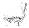
- a support device 2 for a seat 3 and a backrest 4 is rigidly attached to an upper telescopic member 1 of the chair column.
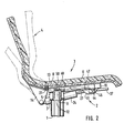
- the carrying device 2 consists of a bent and laterally bent sheet metal plate 6 connected to the telescopic member 1 via a short U-profile 5.
- the U-profile 5 lies with its back 7 (FIG. 2) on the end face of the telescopic member 1 and with the edges its legs on the bottom 8 of the cranking of the sheet metal plate 6.
- a hollow cone 9 is seated in aligned recesses in the back 7 and the bottom 8.
- a gas spring 12 which is supported in the lower telescopic member of the column and which carries everything, projects into the hollow cone 9.
- a bracket 14 of the backrest 4 is connected in an articulated manner to the sheet metal plate 6 by a torsion spring unit 13 of a known type.
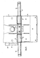
- Fig. 4 shows the welded connections on the one hand with the sheet metal plate 6 at 15 and on the other hand with the bracket 14 at 16.
- 4 shows the torque support of the torsion spring unit 13 via a lever 17 against a projection 18 on the sheet metal plate 6; the end of the lever 6 cannot be seen, where a stud screw provided with a screw handle 19 passes through a thread attached to the lever 17 and its end rests on the projection 18.
- the torsion bar 41 itself, as shown in FIGS. 1 and 2, is divided into four; it therefore has a comparatively soft characteristic. Its pretension, which the console 14 tries to pivot upwards and forwards, can be adjusted with the stud screw 20.
- FIG. 5 further shows the torsion spring unit 13 in detail:
- Two sleeves 51 are welded to the sheet metal plate 6 at 15, a sleeve 52 is welded to the bracket 14 at 16.
- Two tubes 53 and 54 which are in turn aligned, extend through the aligned sleeves 51 and 52. Together with the sleeves 51 and 52, they form a joint as the hinge axis.
- the outer ends of the tubes 53 and 54 are connected to each other by the torsion bar 21.
- the tube 53 is supported on the projection 18 of the sheet metal plate 6 via the lever 17.
- the power transmission takes place from the tube 53 via the torsion bar 21 and the tube 54 to the sleeve 52 welded to the tube 54 at 55 and thus into the bracket 14.
- the force generated by the preload is held by a lockable hydraulic motion damper 24, which is articulated at 22 on the bracket 14 and at 23 on the support device 2.
- the articulated connection with the support device 2 consists in particular of a two-legged bearing block 25 attached to the sheet metal plate 6 , in the two legs not shown stub axles of a head 26 of the piston rod 27 of the hydraulic damper 24 are articulated.
- the connection to the console 14 and, moreover, the structure of the console 14 can be seen in more detail in FIG. 3.
- the console 14 consists of a slightly angled base plate 28 and three projecting console plates 29 welded to it, which are connected to one another by a cross bar 30.
- the crossbar 30 passes through an eyelet 31 of the movement damper 24.
- Shaped plywood panels 32 and 33 are fastened on the sheet metal plate 6 and the base plate 28, which together with cushion pads 34 and 35 form the seat 3 and the backrest 4.
- the torsion spring unit 13 protrudes with its cross-section relatively far above the sheet metal plate 6 and the console 14 upwards and is thus largely between the plywood plates 32 and 33.
- the plywood plate 33 can thus be brought into different angular positions with respect to the plywood plate 32 without being between gives them a gap or nudge, so the seat and backrest act together as a shell.
- the following device is used to adjust the backrest 3 to the rear or to the front:
- a shaft 36 mounted in the two-leg bearing block 25 extends up to close to the side edge of the seat and is provided here with a hand lever 37.
- a cam 38 sits on the shaft 36 between the two legs of the bearing block. It has a flat contact surface 39 and, following this, a contact surface 40 which is curved concentrically to the shaft 36 for a bent leaf spring 41 fastened to the sheet metal plate 6.
- a pivoting of the hand lever from the drawn output position out, in whatever direction, the leaf spring 41 tensions further, ie the hand lever 37 and the cam 38 are held by the leaf spring 41 in the starting position.
- the leaf spring 41 By pivoting the hand lever 37 downward, the leaf spring 41 is pushed back; finally, the curved contact surface 40 bears against the leaf spring 41.
- the leaf spring 41 presses a mandrel 42 protruding from the head 26 of the piston rod 27 into the head 26, whereby the hydraulic movement damper 24 is unlocked and the backrest 4 can be pivoted.
- the height of the seat 3 including the backrest 4 can be adjusted using the following device:
- a shaft 44 provided there with a hand lever 43 extends from the other side edge of the seat to a two-legged bracket 45 in which it is mounted.
- a plate 46 is welded to the shaft 44 between the legs of the bracket 45, whereby two cams forming an extended angle are easily created.
- a rod 47 On the plate 46 is a rod 47 which is mounted with an angled portion 48 in the side walls 10 of the cranking of the plate 6 mentioned.
- a sheet 49 is welded to the section 48 within the crank, which lies on a mandrel 50 protruding from the gas spring 12.
- the plate 46 lifts the rod 47.
- the plate 49 is thus pivoted downward and the mandrel 50 is pressed in by it.
- the gas spring 12 is unlocked and the seat 3 together with the backrest 4 can be moved up and down.
Landscapes
- Health & Medical Sciences (AREA)
- Dentistry (AREA)
- General Health & Medical Sciences (AREA)
- Chairs Characterized By Structure (AREA)
Applications Claiming Priority (2)
| Application Number | Priority Date | Filing Date | Title |
|---|---|---|---|
| DE3835003 | 1988-10-14 | ||
| DE3835003A DE3835003A1 (de) | 1988-10-14 | 1988-10-14 | Sessel oder stuhl, insbesondere buerosessel oder -stuhl |
Publications (2)
| Publication Number | Publication Date |
|---|---|
| EP0363833A1 true EP0363833A1 (fr) | 1990-04-18 |
| EP0363833B1 EP0363833B1 (fr) | 1993-05-19 |
Family
ID=6365108
Family Applications (1)
| Application Number | Title | Priority Date | Filing Date |
|---|---|---|---|
| EP89118551A Expired - Lifetime EP0363833B1 (fr) | 1988-10-14 | 1989-10-06 | Chaise, en particulier chaise de bureau |
Country Status (3)
| Country | Link |
|---|---|
| US (1) | US5069496A (fr) |
| EP (1) | EP0363833B1 (fr) |
| DE (2) | DE3835003A1 (fr) |
Cited By (3)
| Publication number | Priority date | Publication date | Assignee | Title |
|---|---|---|---|---|
| WO1992003072A1 (fr) * | 1990-08-20 | 1992-03-05 | Ring Mekanikk A.S. | Ressort de torsion et support reglable pour siege l'utilisant |
| US9526339B2 (en) | 2012-09-20 | 2016-12-27 | Steelcase Inc. | Control assembly for chair |
| US11304528B2 (en) | 2012-09-20 | 2022-04-19 | Steelcase Inc. | Chair assembly with upholstery covering |
Families Citing this family (25)
| Publication number | Priority date | Publication date | Assignee | Title |
|---|---|---|---|---|
| DE4220307C2 (de) * | 1991-06-26 | 2002-11-21 | Okamura Corp | Stuhl |
| US5389062A (en) * | 1992-10-05 | 1995-02-14 | Mitchum, Jr.; John T. | Intercourse-facilitating therapeutic furniture |
| US5630643A (en) | 1993-06-01 | 1997-05-20 | Steelcase Inc | Upholstered chair with two-piece shell |
| DE4326609C2 (de) * | 1993-08-07 | 1996-03-28 | Taipei Design Center Duesseldo | Bürodrehstuhl |
| US5577807A (en) | 1994-06-09 | 1996-11-26 | Steelcase Inc. | Adjustable chair actuator |
| DE4436145A1 (de) * | 1994-10-11 | 1996-04-18 | Kusch Co Sitzmoebel | Sitzmöbel |
| US5577804A (en) * | 1995-06-30 | 1996-11-26 | Global Upholstery Company | Seat height adjustment mechanism for a chair |
| US5899530A (en) | 1995-08-23 | 1999-05-04 | Global Upholstery Company | Control mechanism for a chair |
| AU4315397A (en) * | 1996-10-14 | 1998-05-11 | Protoned B.V. | Chair frame, control mechanism and upholstery |
| US6065803A (en) * | 1999-05-05 | 2000-05-23 | L&P Property Management Company | Seat back tilt control apparatus |
| US6386528B1 (en) | 1999-07-08 | 2002-05-14 | Lord Corporation | Damper including resilient friction member and seat assembly using same |
| US6698431B1 (en) * | 1999-09-01 | 2004-03-02 | Compass Institute, Inc. | Apparatus and method for supporting human body during itimate activity |
| US6533352B1 (en) * | 2000-07-07 | 2003-03-18 | Virco Mgmt. Corporation | Chair with reclining back rest |
| US6755473B2 (en) | 2000-11-22 | 2004-06-29 | Herman Miller, Inc. | Fluid control system for an office furniture device |
| MY134768A (en) * | 2002-01-17 | 2007-12-31 | Green Continental Furniture M Sdn Bhd | A dining chair with reclining mechanism |
| US7293833B2 (en) * | 2005-02-02 | 2007-11-13 | Itoki Corporation | Chair and support mechanism unit thereof |
| US20070102979A1 (en) * | 2005-10-25 | 2007-05-10 | GLOBAL TOTAL OFFICE an Ontario limited partnership having GLOBAL UPHOLSTERY CO. | Adjustment mechanism for a chair and method for replacing a telescoping cylinder in a reconfigurable chair |
| US7708346B2 (en) * | 2006-10-13 | 2010-05-04 | L&P Property Management Company | Reclining back mechanism for a seating unit |
| US20100141002A1 (en) * | 2008-06-04 | 2010-06-10 | Kurrasch Andrew J | Biasing mechanism |
| US8167373B2 (en) * | 2008-06-06 | 2012-05-01 | Knoll, Inc. | Height adjustment mechanism for a chair |
| NZ613957A (en) | 2008-12-12 | 2015-03-27 | Formway Furniture Ltd | A chair, a support, and components |
| JP2010227324A (ja) * | 2009-03-27 | 2010-10-14 | Oki Electric Ind Co Ltd | 椅子 |
| US20120139318A1 (en) * | 2010-12-07 | 2012-06-07 | Chuen-Jong Tseng | Chair |
| US9504327B2 (en) * | 2015-02-09 | 2016-11-29 | Harmony Lifestyle, LLC | Reclinable chair having a locking gas spring reclining back rest |
| IT201800002761U1 (it) * | 2018-06-14 | 2019-12-14 | Poltroncina per ufficio con schienale e sedile mobili in sincronia. |
Citations (1)
| Publication number | Priority date | Publication date | Assignee | Title |
|---|---|---|---|---|
| GB2195238A (en) * | 1986-09-24 | 1988-04-07 | Giroflex Entwicklungs Ag | Chair frame |
Family Cites Families (8)
| Publication number | Priority date | Publication date | Assignee | Title |
|---|---|---|---|---|
| US2019138A (en) * | 1933-06-17 | 1935-10-29 | Steel Wheel Corp | Internal combustion engine |
| DE2733322C3 (de) * | 1977-07-23 | 1980-08-07 | Protoned B.V., Amsterdam | Arbeitsstuhl |
| US4408800A (en) * | 1980-06-11 | 1983-10-11 | American Seating Company | Office chairs |
| JPS59207112A (ja) * | 1983-05-10 | 1984-11-24 | メ−コ−工業株式会社 | 椅子 |
| US4561693A (en) * | 1983-06-10 | 1985-12-31 | Knoll International, Inc. | Back support tilt and seat and back support height control mechanism for a chair or the like |
| DE3334424A1 (de) * | 1983-09-23 | 1985-04-11 | Girsberger AG, Bützberg | Bedienungsmechanismus fuer sitzmoebel |
| DE8625711U1 (de) * | 1986-09-26 | 1986-11-06 | Kuhn, Günther, 6680 Neunkirchen | Sessel oder Stuhl, insbesondere Bürosessel oder -stuhl |
| EP0300957B1 (fr) * | 1987-07-24 | 1991-07-31 | Equus Marketing Ag | Chaise de travail |
-
1988
- 1988-10-14 DE DE3835003A patent/DE3835003A1/de not_active Withdrawn
-
1989
- 1989-10-06 EP EP89118551A patent/EP0363833B1/fr not_active Expired - Lifetime
- 1989-10-06 DE DE8989118551T patent/DE58904416D1/de not_active Expired - Fee Related
- 1989-10-13 US US07/421,522 patent/US5069496A/en not_active Expired - Fee Related
Patent Citations (1)
| Publication number | Priority date | Publication date | Assignee | Title |
|---|---|---|---|---|
| GB2195238A (en) * | 1986-09-24 | 1988-04-07 | Giroflex Entwicklungs Ag | Chair frame |
Cited By (8)
| Publication number | Priority date | Publication date | Assignee | Title |
|---|---|---|---|---|
| WO1992003072A1 (fr) * | 1990-08-20 | 1992-03-05 | Ring Mekanikk A.S. | Ressort de torsion et support reglable pour siege l'utilisant |
| US5378039A (en) * | 1990-08-20 | 1995-01-03 | Ring Mekanikk As | Torsion spring and adjustable mounting for chair |
| US9526339B2 (en) | 2012-09-20 | 2016-12-27 | Steelcase Inc. | Control assembly for chair |
| US9844267B2 (en) | 2012-09-20 | 2017-12-19 | Steelcase Inc. | Chair back mechanism and control assembly |
| US9861201B2 (en) | 2012-09-20 | 2018-01-09 | Steelcase, Inc. | Chair assembly |
| US9918552B2 (en) | 2012-09-20 | 2018-03-20 | Steelcase Inc. | Control assembly for chair |
| US10206507B2 (en) | 2012-09-20 | 2019-02-19 | Steelcase Inc. | Control assembly for chair |
| US11304528B2 (en) | 2012-09-20 | 2022-04-19 | Steelcase Inc. | Chair assembly with upholstery covering |
Also Published As
| Publication number | Publication date |
|---|---|
| DE3835003A1 (de) | 1990-04-19 |
| DE58904416D1 (de) | 1993-06-24 |
| EP0363833B1 (fr) | 1993-05-19 |
| US5069496A (en) | 1991-12-03 |
Similar Documents
| Publication | Publication Date | Title |
|---|---|---|
| EP0363833B1 (fr) | Chaise, en particulier chaise de bureau | |
| DE3915947C2 (de) | Sitzmöbel | |
| DE60005810T2 (de) | Fussstütze und möbelstück | |
| DE2459908C3 (de) | Ausziehvorrichtung für eine Fußstütze bei einem Lehnsessel | |
| DE2712308A1 (de) | Verstellbarer, von einer wand entfernbarer lehnstuhl | |
| DE3103188A1 (de) | Verstellbarer lehnstuhl | |
| DE19830418B4 (de) | Stuhlanordnung | |
| DE2717331A1 (de) | Stuhl mit verstellbarer rueckenlehne | |
| CH668356A5 (de) | Sessel mit verstellbarer ruecklehne. | |
| DE2425731A1 (de) | Verstellbarer liegestuhl | |
| DE4137034A1 (de) | Rollstuhl mit zusammengesetztem rahmen | |
| DE3002032A1 (de) | Verstellbarer lehnstuhl mit wandausweichender wirkung | |
| EP1632152A2 (fr) | Meuble d'assise | |
| DE3124767C2 (de) | Rohrrahmengerüst für einen Stuhl | |
| DE1964837U (de) | Verstellbarer sessel. | |
| EP2943094B1 (fr) | Siège | |
| DE2332751A1 (de) | Verstellbarer lehnstuhl mit zweiteiliger rueckenstuetze | |
| DE102011051966B4 (de) | Stuhl | |
| DE2342225A1 (de) | Stuhl mit einer auf- und abbewegbaren rueckenlehne | |
| DE1774517U (de) | Ruhemoebel mit zurueckschiebbarem lehnensitz und selbsttaetig nach vorn ausschwenkbarer beinstuetze. | |
| EP0347538A1 (fr) | Chaise, notamment chaise de bureau | |
| DE7630781U1 (de) | Stuhl, sessel oder dergleichen sitzmoebel | |
| DE2362029A1 (de) | Verstellvorrichtung, insbesondere fuer die ausfuehrung einer kippbewegung der sitzflaeche eines krankenstuhls oder des kopfbzw. fussteils eines bettes | |
| DE69919832T2 (de) | Sofabett mit neuartigem Mechanismus zur Positionseinstellung und zum schnellen Zusammenbau | |
| DE3742465C2 (fr) |
Legal Events
| Date | Code | Title | Description |
|---|---|---|---|
| PUAI | Public reference made under article 153(3) epc to a published international application that has entered the european phase |
Free format text: ORIGINAL CODE: 0009012 |
|
| AK | Designated contracting states |
Kind code of ref document: A1 Designated state(s): BE DE FR GB IT NL |
|
| 17P | Request for examination filed |
Effective date: 19901013 |
|
| 17Q | First examination report despatched |
Effective date: 19920220 |
|
| GRAA | (expected) grant |
Free format text: ORIGINAL CODE: 0009210 |
|
| AK | Designated contracting states |
Kind code of ref document: B1 Designated state(s): BE DE FR GB IT NL |
|
| PG25 | Lapsed in a contracting state [announced via postgrant information from national office to epo] |
Ref country code: IT Free format text: LAPSE BECAUSE OF FAILURE TO SUBMIT A TRANSLATION OF THE DESCRIPTION OR TO PAY THE FEE WITHIN THE PRE;WARNING: LAPSES OF ITALIAN PATENTS WITH EFFECTIVE DATE BEFORE 2007 MAY HAVE OCCURRED AT ANY TIME BEFORE 2007. THE CORRECT EFFECTIVE DATE MAY BE DIFFERENT FROM THE ONE RECORDED.SCRIBED TIME-LIMIT Effective date: 19930519 Ref country code: BE Effective date: 19930519 Ref country code: NL Effective date: 19930519 Ref country code: FR Effective date: 19930519 Ref country code: GB Effective date: 19930519 |
|
| REF | Corresponds to: |
Ref document number: 58904416 Country of ref document: DE Date of ref document: 19930624 |
|
| EN | Fr: translation not filed | ||
| NLV1 | Nl: lapsed or annulled due to failure to fulfill the requirements of art. 29p and 29m of the patents act | ||
| GBV | Gb: ep patent (uk) treated as always having been void in accordance with gb section 77(7)/1977 [no translation filed] |
Effective date: 19930519 |
|
| PLBE | No opposition filed within time limit |
Free format text: ORIGINAL CODE: 0009261 |
|
| STAA | Information on the status of an ep patent application or granted ep patent |
Free format text: STATUS: NO OPPOSITION FILED WITHIN TIME LIMIT |
|
| 26N | No opposition filed | ||
| PG25 | Lapsed in a contracting state [announced via postgrant information from national office to epo] |
Ref country code: DE Effective date: 19950301 |