EP1632152A2 - Meuble d'assise - Google Patents
Meuble d'assise Download PDFInfo
- Publication number
- EP1632152A2 EP1632152A2 EP05008467A EP05008467A EP1632152A2 EP 1632152 A2 EP1632152 A2 EP 1632152A2 EP 05008467 A EP05008467 A EP 05008467A EP 05008467 A EP05008467 A EP 05008467A EP 1632152 A2 EP1632152 A2 EP 1632152A2
- Authority
- EP
- European Patent Office
- Prior art keywords
- headrest
- fitting
- articulated
- seat
- hinged
- Prior art date
- Legal status (The legal status is an assumption and is not a legal conclusion. Google has not performed a legal analysis and makes no representation as to the accuracy of the status listed.)
- Withdrawn
Links
Images


Classifications
-
- A—HUMAN NECESSITIES
- A47—FURNITURE; DOMESTIC ARTICLES OR APPLIANCES; COFFEE MILLS; SPICE MILLS; SUCTION CLEANERS IN GENERAL
- A47C—CHAIRS; SOFAS; BEDS
- A47C7/00—Parts, details, or accessories of chairs or stools
- A47C7/36—Support for the head or the back
- A47C7/40—Support for the head or the back for the back
- A47C7/402—Support for the head or the back for the back adjustable in height
-
- A—HUMAN NECESSITIES
- A47—FURNITURE; DOMESTIC ARTICLES OR APPLIANCES; COFFEE MILLS; SPICE MILLS; SUCTION CLEANERS IN GENERAL
- A47C—CHAIRS; SOFAS; BEDS
- A47C1/00—Chairs adapted for special purposes
- A47C1/02—Reclining or easy chairs
- A47C1/031—Reclining or easy chairs having coupled concurrently adjustable supporting parts
- A47C1/036—Reclining or easy chairs having coupled concurrently adjustable supporting parts the parts including a head-rest
-
- A—HUMAN NECESSITIES
- A47—FURNITURE; DOMESTIC ARTICLES OR APPLIANCES; COFFEE MILLS; SPICE MILLS; SUCTION CLEANERS IN GENERAL
- A47C—CHAIRS; SOFAS; BEDS
- A47C7/00—Parts, details, or accessories of chairs or stools
- A47C7/36—Support for the head or the back
- A47C7/38—Support for the head or the back for the head
Definitions
- the invention relates to seating furniture with a body which rests on a footprint, having a rear wall and side walls with or without armrests, with a seat part which is movably supported on the body and from a seating position in which the seat part is approximately horizontal or slightly to the rear wall sloping inclined position assumes, in a relaxation position in which the seat part to the front of the body, on the front further protruding, is adjusted and preferably also sloping sloping towards the rear wall, is adjustable, with a scholar mediatoreil, which via first coupling fitting parts with its lower , the rear end of the seat portion adjacent region is connected to the rear wall facing the end portion of the seat part, so that the conversiganeil is displaced in seated seat part with its lower end to the rear wall and a slightly inclined inclined position occupies and seated in relax position with his lower end further from the is further spaced from the rear wall and preferably occupies a more inclined relaxation position, wherein at the upper, the seat part facing away from thematiceniils a headrest
- seating in which the seat part is displaceable by the user from a sitting position to a relax position, wherein the Spotify constituenteil is coupled to the seat part, so that it is taken in the forward displacement of the seat part in the relaxed position and from a steep Position is adjusted to a weaker inclined position. Furthermore, it is known to arrange a headrest on the backrest part, which is arranged adjustably on the upper edge of the backrest part.
- an actuating lever is usually provided for adjustment.
- the headrest or the head part also follows in the case of the solutions known in the prior art during the displacement from the sitting position to the relaxed position the backrest part.
- the headrest is pivoted in the seated position parts to the rear, so that it forms a quasi an approximately flat upper boundary surface above the backrest of the chair.
- the headrest pivots forward so that the user can put his head on it.
- the headrest part is arranged virtually fixed to the frame pivotally and is necessarily taken by a coupling fitting upon adjustment of the seat part from the sitting position to the relaxed position and back to the sitting position and adjusted in the different positions. In this case, the inclination change and the relative displacement of the consideredeils down without the headrest part participates this movement.
- the felt medicinaleil is reinforced in the lower, the seat part adjacent end portion by an auxiliary frame, are attached to the parts of the first coupling fitting.
- the headrest on the notedeil facing end portion preferably on the back, a stiffening, on which the joint of the frame-fixed component of the function fitting is arranged and on which the control part of the function fitting is articulated for pivoting the headrest.
- the frame-fixed component consists of a rod which is attached with its one end in the area behind the considered constitutionaleil near its lower end on the body or on carcass-proof parts of the chair, and with its other end on the back of the headrest near the Lower end of the swivel joint of the headrest is articulated forming.
- the second coupling fitting which forms or comprises the actuating part, consists of a first adjusting lever, which is articulated at one end to the headrest near the articulation region of the frame-fixed component, in particular the rod, and the other end to a is articulated second adjusting lever, which crosses the frame-fixed component, in particular the rod, is articulated in the intersection of this or this and articulated with the crossing region superior end at one end of a third actuating lever, the other end hinged to components of the first coupling fitting and controlled by its movement.
- the headrest is pivoted in the seated position parts to the rear, so that they quasi forms an approximately flat upper boundary surface above the backrest of the chair. In the relaxed position, the headrest is pivoted forward so that the user can put his head on it.
- the essential feature is that the headrest part is arranged fixed to the frame pivotally and is inevitably taken on adjustment of the seat part from the sitting position to the relaxed position and back to the sitting position and adjusted in the different positions. In this case, the inclination change and the relative displacement of the back part is down, without the headrest part participates this movement.
- the pad can serve as a moving element and support the pivotal movement of the headrest part.
- the headrest is pivoted in located in the sitting position parts to the rear, so that it forms a quasi an approximately flat upper boundary surface above the backrest of the chair. In the relaxed position, the headrest is pivoted forward so that the user can put his head on it.
- the essential feature is that the headrest part is fixed to the frame pivotally mounted and inevitably taken on adjustment of the seat part from the sitting position to the relaxed position and back to the sitting position and is adjusted to the different positions. Also in this training, the inclination change and the relative displacement of the back portion is down, without the headrest part participates this movement.
- the pad can be continuously and hingedly formed in the area between the headrest and the upper end ofmatimatieils, and serve as a moving element to support, for example, the adjustment of the headrest from the sitting to the relaxed position.
- the headrest is pivoted in located in the sitting position parts to the rear, so that it forms a quasi an approximately flat upper boundary surface above the backrest of the chair. In the relaxed position, the headrest is pivoted forward so that the user can put his head on it.
- the essential feature is that the headrest part is arranged fixed to the frame pivotally and is inevitably taken on adjustment of the seat part from the sitting position to the relaxed position and back to the sitting position and adjusted in the different positions. Also at This solution is the slope change and the relative displacement of the back part down, without the headrest part participates this movement.
- the pad is formed continuously and hingedly, and can serve as a moving element to assist the adjustment of the headrest part from the sitting to the relaxed position.
- the headrest is pivoted in the seated position parts to the rear, so that it almost forms an approximately flat upper boundary surface above the backrest of the chair.
- the upholstery of the chair is continuously formed and hinged in the area between the headrest andcomponenteil.
- the pad is provided in this embodiment as a moving element for adjusting the headrest from the sitting to the relaxed position. Also in this configuration, the headrest is pivoted forward in the relaxed position, so that the user can put his head on it.
- the essential feature is that the headrest part is arranged virtually fixed to the frame pivotally and inevitably upon adjustment of the seat part, inter alia, with the help of stretchable pad is taken from the sitting position to the relaxed position and back to the sitting position and adjusted in the different layers. Also, the inclination change and the relative displacement of the back portion is down, without the headrest part participates in the movement.
- the varied quantity of the mealpiece is coupled to the seat part.
- the displacement of the seat part to the front causes an adjustment of the thoroughly constituenteils in the direction of the footprint of the chair.
- the headrest is pivoted in an approximately vertical position when adjusting the suggested quantity of the chair.
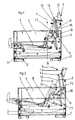
- the chair has a body 1, which rests on feet 2 on a footprint.
- the body 1 has a raised rear wall 3 and likewise raised armrests 4.
- the seating on a seat part 5, which on Body 1 is movably held and from a sitting position shown in Figure 1, in which the seat part 5 assumes an approximately horizontal, slightly sloping towards the rear wall 3 inclined position, in a relax position according to Figure 2, in which the seat part 5 to the front of the body 1 via the front side is further displaced protruding and is sloping sloping towards the rear wall 3, is adjustable.
- a spectrum element 6 is movably held on the body 1 and coupled to the seat part 5.
- the configured BIOeil 6 is connected via first coupling fitting parts 8 with its lower, the rear end of the seat part 5 adjacent area with the rear wall 3 facing end portion of the seat part 5, so that the resonated in sitting position according to Figure 1 seat part 5 with its lower End is displaced to the rear wall 3 and assumes a slightly inclined angle and is at spaced in relax position according to Figure 2 seat part 5 with its lower end further from the rear wall 3 and occupies a more inclined relaxation position.
- the seat part 5 facing away from the backrest 6 is connected to the pureotroeil 6 a headrest 7, which projects beyond the upper end of the rear wall 3.
- the alloy genereil 6, the headrest 7 and the seat part 5 are covered with a cushion.
- the headrest 7 is fixed by means of a functional fitting 9 on the body 1 and held pivotally.
- the headrest 7 is pivotally held on the one hand on a frame fixedly arranged component 10 of the function fitting 9 and on the other hand by means of a second coupling fitting 11 pivotally hinged to the headrest 7 and to components of the first coupling fitting 8.
- the headrest 7 is pivoted by means of the second coupling fitting 11 in the sitting position shown in Figure 1 to the rear and positioned in this position.
- the headrest 7 engages over the upper end of the rear wall 3 and forms a nearly horizontal end surface above the rear wall 3.
- the headrest 7 is pivoted forward and forms an extension of the varied constituenteils 6 for conditioning of the user's head.
- the headrest 7 thus follows the sliding movement of the considered hereineils 6 down or not above.
- the alloyhereil 6 is in the lower, the seat part 5 adjacent end portion reinforced by an auxiliary frame 12, are attached to the parts of the first coupling fitting 8 or articulated.
- the headrest 7 has on its backrest 6 facing end portion on the back of a stiffener 13, on which the joint 14 of the frame-fixed component 10 of the function fitting 9 is arranged and to which the second coupling fitting 11 is articulated as an adjusting part of the function fitting 9 for pivoting the headrest 7 ,
- the frame-fixed component 10 consists of a rod which is fixed with its one end in the area behind the substituted component 6 on the body 1 or on body parts of the seat and the body with its other end on the back of the headrest 7 near the lower end of the pivot joint 14 of the headrest 7 is articulated chanmorend.
- the second coupling fitting 11 which also forms the adjusting part, consists of a first adjusting lever 15, which is articulated at one end to the headrest 7 near the articulation region of the joint 14 of the frame-fixed component 10 and whose other end is articulated to a second adjusting lever 16, which crosses the frame-fixed component 10, in Junction is hinged to this and is articulated with the crossing region projecting end at the end of a third control lever 17, whose other end is hinged to components of the first coupling fitting 8 and controlled by the movement thereof.
- a first fitting part 19 is hinged at its one end to a reinforced by a plate 20 portion of the headrest 7 on the headrest 7.
- the first fitting part 19 is rigidly attached to the body 1.
- a second fitting part 18 is articulated with its one end.
- the articulation point of the first fitting part 19 is spaced from the articulation point of the second fitting part 18.
- the other end of the second fitting part 18 is hinged to the first end of an approximately horizontally disposed lever 22 (at 21).
- the lever 22 is further articulated about its course approximately centrally to the first fitting part 19 (at 23) and with its second end to the subframe 12 of the scholarnostieils. 6 hinged.
- the headrest 7 is pivoted in the sitting position to the rear and overlaps the upper end of the rear wall 3. In the relaxed position, the headrest 7 is swung forward and forms an extension of the varied propositioneils. 6
- a frame member 24 is arranged with a bolt formed thereon on the headrest 7.
- the bolt is guided in a frame fixed to the body 1 plate 25 with a guide slot 26.
- On the frame part 24, the first end of an approximately perpendicular fitting part 27 is articulated.
- the second end of the approximately perpendicular fitting part 27 is hinged to the first end of a lever 28.
- the lever 28 is articulated on the body 1 approximately centrally and at its second end to the subframe 12 of the considered stated partyeils 6.
- the headrest 7 is thus pivoted in the sitting position to the rear and overlaps the upper end of the rear wall 3. In the relaxed position, the headrest 7 is pivoted forward and forms an extension of the varied constitutionaleils. 6
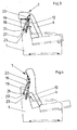
- a frame member in the form of a plate 29 is arranged on the headrest 7.
- On the plate 29 is the first end of an approximately perpendicular fitting part 30th (Adjusting lever) hinged, so that in this pivot point a pivot axis (at 31) is formed for the headrest 7.
- a pressure-tension element in the form of a pull rod 32 is articulated with its first end.
- the articulation region 31 A has a distance from the articulation point 31.
- the second end of the drawbar 32 is fastened to the auxiliary frame 12 of the backrest part 6.
- the second end of the approximately perpendicular fitting part 30 is hinged to parts of the body 1.
- the headrest 7 is pivoted in this embodiment in the sitting position to the rear and overlaps the upper end of the rear wall 3. In the relaxed position, the headrest 7 is pivoted forward and forms an extension of thematiticianeils. 6
- the simplified propositionouseil 6 and the headrest 7 of the chair is provided with a continuous contiguous pad.
- the pad is formed in particular in the transition regiontheibieil 6 / headrest 7 hinged and supports the pivoting movement of the headrest. 7
- a frame part is in the form of a back part on the headrest 7 a rod 33 is arranged.
- the frame part could also be formed by a plate.
- the first end of a guide rod 34 is articulated (at 38).
- guide rod 34 a fixed to the subframe 12 guide sleeve 35 is pushed and guided.
- the second end of the guide rod 34 is hinged to the first end of an approximately perpendicular fitting part 36. (Lever 36).
- the second end 37 of the approximately perpendicular fitting part 36 is articulated on the body 1.
- the upholstery of the seat is formed at least in the transition region at 38.39 of the considered medicinal substanceeil 6 to the headrest 7 hinged and serves as a moving element.
- the headrest 7 is pivoted in the sitting position to the rear. In this position, the headrest engages over the upper end of the rear wall 3 (see Figure 9).
- the headrest 7 In the relaxed position of the embodiment shown in Figure 10, the headrest 7 is pivoted forward and forms an extension of the simplified feelingeils 6.
- the cushion forms an essential element of movement.
Applications Claiming Priority (1)
| Application Number | Priority Date | Filing Date | Title |
|---|---|---|---|
| DE202004013904U DE202004013904U1 (de) | 2004-09-03 | 2004-09-03 | Sitzmöbel |
Publications (2)
| Publication Number | Publication Date |
|---|---|
| EP1632152A2 true EP1632152A2 (fr) | 2006-03-08 |
| EP1632152A3 EP1632152A3 (fr) | 2008-04-23 |
Family
ID=33483538
Family Applications (1)
| Application Number | Title | Priority Date | Filing Date |
|---|---|---|---|
| EP05008467A Withdrawn EP1632152A3 (fr) | 2004-09-03 | 2005-04-19 | Meuble d'assise |
Country Status (4)
| Country | Link |
|---|---|
| US (1) | US7201438B2 (fr) |
| EP (1) | EP1632152A3 (fr) |
| DE (1) | DE202004013904U1 (fr) |
| ZA (1) | ZA200504739B (fr) |
Cited By (2)
| Publication number | Priority date | Publication date | Assignee | Title |
|---|---|---|---|---|
| DE102007049118B3 (de) * | 2007-10-12 | 2009-02-05 | Stanzwerk Wetter Sichelschmidt Gmbh & Co. Kg | Sitzmöbel |
| DE202009000731U1 (de) | 2009-01-22 | 2009-03-26 | Stanzwerk Wetter Sichelschmidt Gmbh & Co. Kg | Sitzmöbel |
Families Citing this family (10)
| Publication number | Priority date | Publication date | Assignee | Title |
|---|---|---|---|---|
| WO2008129567A1 (fr) * | 2007-04-18 | 2008-10-30 | Stema S.R.L. | Mécanisme permettant d'incliner des fauteuils ou des canapés |
| US7862110B2 (en) * | 2007-04-20 | 2011-01-04 | L & P Property Management Company | Headrest for recliner chair |
| DE202008016813U1 (de) * | 2008-12-19 | 2009-03-26 | Rolf Benz Ag & Co. Kg | Sitzmöbel mit lageveränderlicher Kopfstütze |
| US9084708B2 (en) | 2010-12-08 | 2015-07-21 | Broda Enterprises Inc. | Modular chair |
| USD744909S1 (en) * | 2011-06-15 | 2015-12-08 | R82 A/S | Walking frame for disabled |
| USD751468S1 (en) * | 2014-04-01 | 2016-03-15 | Stryker Corporation | Transport apparatus |
| WO2016092249A1 (fr) * | 2014-12-11 | 2016-06-16 | Integrated Furniture Technologies Limited | Meuble réglable |
| US9480336B1 (en) * | 2015-04-15 | 2016-11-01 | American Leather Operations, Llc | Motion furniture with deployable headrest |
| CN209644428U (zh) * | 2018-09-29 | 2019-11-19 | 嘉兴礼海电气科技有限公司 | 一种用于沙发的翻转头靠装置 |
| CN214711596U (zh) * | 2020-12-31 | 2021-11-16 | 张孝兆 | 头枕装置及具有该装置的座椅 |
Citations (4)
| Publication number | Priority date | Publication date | Assignee | Title |
|---|---|---|---|---|
| DE2401231A1 (de) * | 1973-01-12 | 1974-07-25 | La Z Boy Chair Co | Sessel mit verstellbarer rueckenlehne |
| US3871705A (en) * | 1973-10-23 | 1975-03-18 | Mohasco Ind Inc | Chair with projecting headrest and hardware therefor |
| EP0277870A1 (fr) * | 1987-01-23 | 1988-08-10 | Tousalon France S.A. | Dispositif de manoeuvre pour fauteuil, siège ou canapé à positions multiples comportant un cale reins |
| US5340191A (en) * | 1993-04-07 | 1994-08-23 | The Lane Company, Inc. | Reclining chair having pop-up headrest |
Family Cites Families (7)
| Publication number | Priority date | Publication date | Assignee | Title |
|---|---|---|---|---|
| US4386803A (en) * | 1981-11-05 | 1983-06-07 | Gilderbloom Clarence W | Motorized reclining chair |
| US4691961A (en) * | 1986-02-14 | 1987-09-08 | Parma Corporation | Recliner with headrest |
| BR8804019A (pt) * | 1988-07-29 | 1988-11-16 | Percival Lafer | Poltrona reclinavel |
| US5346277A (en) * | 1992-07-30 | 1994-09-13 | Parma Corporation | Foldable headrest mechanism |
| US5374100A (en) * | 1993-03-12 | 1994-12-20 | Ultra-Mek, Inc. | Adjustable foldable headrest |
| US5310243A (en) * | 1993-03-26 | 1994-05-10 | Dbju, Inc. | Headrest support assembly for recliner chair |
| US5464269A (en) * | 1993-10-12 | 1995-11-07 | Mizelle; Ned W. | Upholstered furniture and movable headrest |
-
2004
- 2004-09-03 DE DE202004013904U patent/DE202004013904U1/de not_active Expired - Lifetime
-
2005
- 2005-04-19 EP EP05008467A patent/EP1632152A3/fr not_active Withdrawn
- 2005-08-31 US US11/217,116 patent/US7201438B2/en not_active Expired - Fee Related
-
2006
- 2006-02-10 ZA ZA200504739A patent/ZA200504739B/xx unknown
Patent Citations (4)
| Publication number | Priority date | Publication date | Assignee | Title |
|---|---|---|---|---|
| DE2401231A1 (de) * | 1973-01-12 | 1974-07-25 | La Z Boy Chair Co | Sessel mit verstellbarer rueckenlehne |
| US3871705A (en) * | 1973-10-23 | 1975-03-18 | Mohasco Ind Inc | Chair with projecting headrest and hardware therefor |
| EP0277870A1 (fr) * | 1987-01-23 | 1988-08-10 | Tousalon France S.A. | Dispositif de manoeuvre pour fauteuil, siège ou canapé à positions multiples comportant un cale reins |
| US5340191A (en) * | 1993-04-07 | 1994-08-23 | The Lane Company, Inc. | Reclining chair having pop-up headrest |
Cited By (3)
| Publication number | Priority date | Publication date | Assignee | Title |
|---|---|---|---|---|
| DE102007049118B3 (de) * | 2007-10-12 | 2009-02-05 | Stanzwerk Wetter Sichelschmidt Gmbh & Co. Kg | Sitzmöbel |
| BE1019598A5 (fr) * | 2007-10-12 | 2012-09-04 | Sichelschmidt Stanzwerk | Siege reglable. |
| DE202009000731U1 (de) | 2009-01-22 | 2009-03-26 | Stanzwerk Wetter Sichelschmidt Gmbh & Co. Kg | Sitzmöbel |
Also Published As
| Publication number | Publication date |
|---|---|
| ZA200504739B (en) | 2006-03-29 |
| EP1632152A3 (fr) | 2008-04-23 |
| US7201438B2 (en) | 2007-04-10 |
| DE202004013904U1 (de) | 2004-11-18 |
| US20060049673A1 (en) | 2006-03-09 |
Similar Documents
| Publication | Publication Date | Title |
|---|---|---|
| EP1632152A2 (fr) | Meuble d'assise | |
| DE102010014126B4 (de) | Sitzmöbel mit einem in eine Aufstehhilfesposition schwenkbaren Sitz | |
| EP1911371B1 (fr) | Meuble d'assise, en particulier chaise de bureau | |
| DE2459109C3 (de) | Beschlaggestänge für einen Lehnsessel | |
| DE3817761C2 (fr) | ||
| WO2001091614A1 (fr) | Chaise | |
| WO1980002102A1 (fr) | Fauteuil | |
| DE102007049118B3 (de) | Sitzmöbel | |
| DE3002032A1 (de) | Verstellbarer lehnstuhl mit wandausweichender wirkung | |
| DE1294618B (de) | Verstellbarer Schaukelstuhl | |
| DE202006005139U1 (de) | Sitz-/Liegemöbel mit Sitztiefenverstellung | |
| DE102006013119A1 (de) | Sitzmöbel mit Rückenlehne und verstellbarer Kopfstütze | |
| EP2893844B1 (fr) | Siège doté d'un élément de tête pivotant motorisé | |
| DE4219599C2 (de) | Synchronverstelleinrichtung für Bürostühle oder dergleichen | |
| DE102006016646B4 (de) | Sitzmöbel | |
| DE202006016889U1 (de) | Sitzmöbel | |
| DE202006006004U1 (de) | Bettrahmen | |
| EP2111138B1 (fr) | Meuble d'assise avec un element pour pieds pivotant | |
| DE202006005301U1 (de) | Bettrahmen | |
| DE202005005928U1 (de) | Sitzmöbel | |
| DE4236195A1 (de) | Kranken- oder Pflegebett | |
| DE10044629C2 (de) | Funktionsbeschlag für Polstermöbel | |
| DE202009000731U1 (de) | Sitzmöbel | |
| DE2757652A1 (de) | Beschlag fuer einen in eine sitzstellung und in eine ruhestellung einstellbaren sessel mit fusstuetze | |
| DE202006013897U1 (de) | Sitz- und/oder Liegemöbel mit verstellbarer Arm- und/oder Rückenlehne |
Legal Events
| Date | Code | Title | Description |
|---|---|---|---|
| PUAI | Public reference made under article 153(3) epc to a published international application that has entered the european phase |
Free format text: ORIGINAL CODE: 0009012 |
|
| AK | Designated contracting states |
Kind code of ref document: A2 Designated state(s): AT BE BG CH CY CZ DE DK EE ES FI FR GB GR HU IE IS IT LI LT LU MC NL PL PT RO SE SI SK TR |
|
| AX | Request for extension of the european patent |
Extension state: AL BA HR LV MK YU |
|
| PUAL | Search report despatched |
Free format text: ORIGINAL CODE: 0009013 |
|
| AK | Designated contracting states |
Kind code of ref document: A3 Designated state(s): AT BE BG CH CY CZ DE DK EE ES FI FR GB GR HU IE IS IT LI LT LU MC NL PL PT RO SE SI SK TR |
|
| AX | Request for extension of the european patent |
Extension state: AL BA HR LV MK YU |
|
| AKX | Designation fees paid | ||
| STAA | Information on the status of an ep patent application or granted ep patent |
Free format text: STATUS: THE APPLICATION IS DEEMED TO BE WITHDRAWN |
|
| 18D | Application deemed to be withdrawn |
Effective date: 20081024 |
|
| REG | Reference to a national code |
Ref country code: DE Ref legal event code: 8566 |