EP1632152A2 - Seating furniture - Google Patents
Seating furniture Download PDFInfo
- Publication number
- EP1632152A2 EP1632152A2 EP05008467A EP05008467A EP1632152A2 EP 1632152 A2 EP1632152 A2 EP 1632152A2 EP 05008467 A EP05008467 A EP 05008467A EP 05008467 A EP05008467 A EP 05008467A EP 1632152 A2 EP1632152 A2 EP 1632152A2
- Authority
- EP
- European Patent Office
- Prior art keywords
- headrest
- fitting
- articulated
- seat
- hinged
- Prior art date
- Legal status (The legal status is an assumption and is not a legal conclusion. Google has not performed a legal analysis and makes no representation as to the accuracy of the status listed.)
- Withdrawn
Links
Images


Classifications
-
- A—HUMAN NECESSITIES
- A47—FURNITURE; DOMESTIC ARTICLES OR APPLIANCES; COFFEE MILLS; SPICE MILLS; SUCTION CLEANERS IN GENERAL
- A47C—CHAIRS; SOFAS; BEDS
- A47C7/00—Parts, details, or accessories of chairs or stools
- A47C7/36—Support for the head or the back
- A47C7/40—Support for the head or the back for the back
- A47C7/402—Support for the head or the back for the back adjustable in height
-
- A—HUMAN NECESSITIES
- A47—FURNITURE; DOMESTIC ARTICLES OR APPLIANCES; COFFEE MILLS; SPICE MILLS; SUCTION CLEANERS IN GENERAL
- A47C—CHAIRS; SOFAS; BEDS
- A47C1/00—Chairs adapted for special purposes
- A47C1/02—Reclining or easy chairs
- A47C1/031—Reclining or easy chairs having coupled concurrently adjustable supporting parts
- A47C1/036—Reclining or easy chairs having coupled concurrently adjustable supporting parts the parts including a head-rest
-
- A—HUMAN NECESSITIES
- A47—FURNITURE; DOMESTIC ARTICLES OR APPLIANCES; COFFEE MILLS; SPICE MILLS; SUCTION CLEANERS IN GENERAL
- A47C—CHAIRS; SOFAS; BEDS
- A47C7/00—Parts, details, or accessories of chairs or stools
- A47C7/36—Support for the head or the back
- A47C7/38—Support for the head or the back for the head
Definitions
- the invention relates to seating furniture with a body which rests on a footprint, having a rear wall and side walls with or without armrests, with a seat part which is movably supported on the body and from a seating position in which the seat part is approximately horizontal or slightly to the rear wall sloping inclined position assumes, in a relaxation position in which the seat part to the front of the body, on the front further protruding, is adjusted and preferably also sloping sloping towards the rear wall, is adjustable, with a scholar mediatoreil, which via first coupling fitting parts with its lower , the rear end of the seat portion adjacent region is connected to the rear wall facing the end portion of the seat part, so that the conversiganeil is displaced in seated seat part with its lower end to the rear wall and a slightly inclined inclined position occupies and seated in relax position with his lower end further from the is further spaced from the rear wall and preferably occupies a more inclined relaxation position, wherein at the upper, the seat part facing away from thematiceniils a headrest
- seating in which the seat part is displaceable by the user from a sitting position to a relax position, wherein the Spotify constituenteil is coupled to the seat part, so that it is taken in the forward displacement of the seat part in the relaxed position and from a steep Position is adjusted to a weaker inclined position. Furthermore, it is known to arrange a headrest on the backrest part, which is arranged adjustably on the upper edge of the backrest part.
- an actuating lever is usually provided for adjustment.
- the headrest or the head part also follows in the case of the solutions known in the prior art during the displacement from the sitting position to the relaxed position the backrest part.
- the headrest is pivoted in the seated position parts to the rear, so that it forms a quasi an approximately flat upper boundary surface above the backrest of the chair.
- the headrest pivots forward so that the user can put his head on it.
- the headrest part is arranged virtually fixed to the frame pivotally and is necessarily taken by a coupling fitting upon adjustment of the seat part from the sitting position to the relaxed position and back to the sitting position and adjusted in the different positions. In this case, the inclination change and the relative displacement of the consideredeils down without the headrest part participates this movement.
- the felt medicinaleil is reinforced in the lower, the seat part adjacent end portion by an auxiliary frame, are attached to the parts of the first coupling fitting.
- the headrest on the notedeil facing end portion preferably on the back, a stiffening, on which the joint of the frame-fixed component of the function fitting is arranged and on which the control part of the function fitting is articulated for pivoting the headrest.
- the frame-fixed component consists of a rod which is attached with its one end in the area behind the considered constitutionaleil near its lower end on the body or on carcass-proof parts of the chair, and with its other end on the back of the headrest near the Lower end of the swivel joint of the headrest is articulated forming.
- the second coupling fitting which forms or comprises the actuating part, consists of a first adjusting lever, which is articulated at one end to the headrest near the articulation region of the frame-fixed component, in particular the rod, and the other end to a is articulated second adjusting lever, which crosses the frame-fixed component, in particular the rod, is articulated in the intersection of this or this and articulated with the crossing region superior end at one end of a third actuating lever, the other end hinged to components of the first coupling fitting and controlled by its movement.
- the headrest is pivoted in the seated position parts to the rear, so that they quasi forms an approximately flat upper boundary surface above the backrest of the chair. In the relaxed position, the headrest is pivoted forward so that the user can put his head on it.
- the essential feature is that the headrest part is arranged fixed to the frame pivotally and is inevitably taken on adjustment of the seat part from the sitting position to the relaxed position and back to the sitting position and adjusted in the different positions. In this case, the inclination change and the relative displacement of the back part is down, without the headrest part participates this movement.
- the pad can serve as a moving element and support the pivotal movement of the headrest part.
- the headrest is pivoted in located in the sitting position parts to the rear, so that it forms a quasi an approximately flat upper boundary surface above the backrest of the chair. In the relaxed position, the headrest is pivoted forward so that the user can put his head on it.
- the essential feature is that the headrest part is fixed to the frame pivotally mounted and inevitably taken on adjustment of the seat part from the sitting position to the relaxed position and back to the sitting position and is adjusted to the different positions. Also in this training, the inclination change and the relative displacement of the back portion is down, without the headrest part participates this movement.
- the pad can be continuously and hingedly formed in the area between the headrest and the upper end ofmatimatieils, and serve as a moving element to support, for example, the adjustment of the headrest from the sitting to the relaxed position.
- the headrest is pivoted in located in the sitting position parts to the rear, so that it forms a quasi an approximately flat upper boundary surface above the backrest of the chair. In the relaxed position, the headrest is pivoted forward so that the user can put his head on it.
- the essential feature is that the headrest part is arranged fixed to the frame pivotally and is inevitably taken on adjustment of the seat part from the sitting position to the relaxed position and back to the sitting position and adjusted in the different positions. Also at This solution is the slope change and the relative displacement of the back part down, without the headrest part participates this movement.
- the pad is formed continuously and hingedly, and can serve as a moving element to assist the adjustment of the headrest part from the sitting to the relaxed position.
- the headrest is pivoted in the seated position parts to the rear, so that it almost forms an approximately flat upper boundary surface above the backrest of the chair.
- the upholstery of the chair is continuously formed and hinged in the area between the headrest andcomponenteil.
- the pad is provided in this embodiment as a moving element for adjusting the headrest from the sitting to the relaxed position. Also in this configuration, the headrest is pivoted forward in the relaxed position, so that the user can put his head on it.
- the essential feature is that the headrest part is arranged virtually fixed to the frame pivotally and inevitably upon adjustment of the seat part, inter alia, with the help of stretchable pad is taken from the sitting position to the relaxed position and back to the sitting position and adjusted in the different layers. Also, the inclination change and the relative displacement of the back portion is down, without the headrest part participates in the movement.
- the varied quantity of the mealpiece is coupled to the seat part.
- the displacement of the seat part to the front causes an adjustment of the thoroughly constituenteils in the direction of the footprint of the chair.
- the headrest is pivoted in an approximately vertical position when adjusting the suggested quantity of the chair.
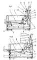
- the chair has a body 1, which rests on feet 2 on a footprint.
- the body 1 has a raised rear wall 3 and likewise raised armrests 4.
- the seating on a seat part 5, which on Body 1 is movably held and from a sitting position shown in Figure 1, in which the seat part 5 assumes an approximately horizontal, slightly sloping towards the rear wall 3 inclined position, in a relax position according to Figure 2, in which the seat part 5 to the front of the body 1 via the front side is further displaced protruding and is sloping sloping towards the rear wall 3, is adjustable.
- a spectrum element 6 is movably held on the body 1 and coupled to the seat part 5.
- the configured BIOeil 6 is connected via first coupling fitting parts 8 with its lower, the rear end of the seat part 5 adjacent area with the rear wall 3 facing end portion of the seat part 5, so that the resonated in sitting position according to Figure 1 seat part 5 with its lower End is displaced to the rear wall 3 and assumes a slightly inclined angle and is at spaced in relax position according to Figure 2 seat part 5 with its lower end further from the rear wall 3 and occupies a more inclined relaxation position.
- the seat part 5 facing away from the backrest 6 is connected to the pureotroeil 6 a headrest 7, which projects beyond the upper end of the rear wall 3.
- the alloy genereil 6, the headrest 7 and the seat part 5 are covered with a cushion.
- the headrest 7 is fixed by means of a functional fitting 9 on the body 1 and held pivotally.
- the headrest 7 is pivotally held on the one hand on a frame fixedly arranged component 10 of the function fitting 9 and on the other hand by means of a second coupling fitting 11 pivotally hinged to the headrest 7 and to components of the first coupling fitting 8.
- the headrest 7 is pivoted by means of the second coupling fitting 11 in the sitting position shown in Figure 1 to the rear and positioned in this position.
- the headrest 7 engages over the upper end of the rear wall 3 and forms a nearly horizontal end surface above the rear wall 3.
- the headrest 7 is pivoted forward and forms an extension of the varied constituenteils 6 for conditioning of the user's head.
- the headrest 7 thus follows the sliding movement of the considered hereineils 6 down or not above.
- the alloyhereil 6 is in the lower, the seat part 5 adjacent end portion reinforced by an auxiliary frame 12, are attached to the parts of the first coupling fitting 8 or articulated.
- the headrest 7 has on its backrest 6 facing end portion on the back of a stiffener 13, on which the joint 14 of the frame-fixed component 10 of the function fitting 9 is arranged and to which the second coupling fitting 11 is articulated as an adjusting part of the function fitting 9 for pivoting the headrest 7 ,
- the frame-fixed component 10 consists of a rod which is fixed with its one end in the area behind the substituted component 6 on the body 1 or on body parts of the seat and the body with its other end on the back of the headrest 7 near the lower end of the pivot joint 14 of the headrest 7 is articulated chanmorend.
- the second coupling fitting 11 which also forms the adjusting part, consists of a first adjusting lever 15, which is articulated at one end to the headrest 7 near the articulation region of the joint 14 of the frame-fixed component 10 and whose other end is articulated to a second adjusting lever 16, which crosses the frame-fixed component 10, in Junction is hinged to this and is articulated with the crossing region projecting end at the end of a third control lever 17, whose other end is hinged to components of the first coupling fitting 8 and controlled by the movement thereof.
- a first fitting part 19 is hinged at its one end to a reinforced by a plate 20 portion of the headrest 7 on the headrest 7.
- the first fitting part 19 is rigidly attached to the body 1.
- a second fitting part 18 is articulated with its one end.
- the articulation point of the first fitting part 19 is spaced from the articulation point of the second fitting part 18.
- the other end of the second fitting part 18 is hinged to the first end of an approximately horizontally disposed lever 22 (at 21).
- the lever 22 is further articulated about its course approximately centrally to the first fitting part 19 (at 23) and with its second end to the subframe 12 of the scholarnostieils. 6 hinged.
- the headrest 7 is pivoted in the sitting position to the rear and overlaps the upper end of the rear wall 3. In the relaxed position, the headrest 7 is swung forward and forms an extension of the varied propositioneils. 6
- a frame member 24 is arranged with a bolt formed thereon on the headrest 7.
- the bolt is guided in a frame fixed to the body 1 plate 25 with a guide slot 26.
- On the frame part 24, the first end of an approximately perpendicular fitting part 27 is articulated.
- the second end of the approximately perpendicular fitting part 27 is hinged to the first end of a lever 28.
- the lever 28 is articulated on the body 1 approximately centrally and at its second end to the subframe 12 of the considered stated partyeils 6.
- the headrest 7 is thus pivoted in the sitting position to the rear and overlaps the upper end of the rear wall 3. In the relaxed position, the headrest 7 is pivoted forward and forms an extension of the varied constitutionaleils. 6
- a frame member in the form of a plate 29 is arranged on the headrest 7.
- On the plate 29 is the first end of an approximately perpendicular fitting part 30th (Adjusting lever) hinged, so that in this pivot point a pivot axis (at 31) is formed for the headrest 7.
- a pressure-tension element in the form of a pull rod 32 is articulated with its first end.
- the articulation region 31 A has a distance from the articulation point 31.
- the second end of the drawbar 32 is fastened to the auxiliary frame 12 of the backrest part 6.
- the second end of the approximately perpendicular fitting part 30 is hinged to parts of the body 1.
- the headrest 7 is pivoted in this embodiment in the sitting position to the rear and overlaps the upper end of the rear wall 3. In the relaxed position, the headrest 7 is pivoted forward and forms an extension of thematiticianeils. 6
- the simplified propositionouseil 6 and the headrest 7 of the chair is provided with a continuous contiguous pad.
- the pad is formed in particular in the transition regiontheibieil 6 / headrest 7 hinged and supports the pivoting movement of the headrest. 7
- a frame part is in the form of a back part on the headrest 7 a rod 33 is arranged.
- the frame part could also be formed by a plate.
- the first end of a guide rod 34 is articulated (at 38).
- guide rod 34 a fixed to the subframe 12 guide sleeve 35 is pushed and guided.
- the second end of the guide rod 34 is hinged to the first end of an approximately perpendicular fitting part 36. (Lever 36).
- the second end 37 of the approximately perpendicular fitting part 36 is articulated on the body 1.
- the upholstery of the seat is formed at least in the transition region at 38.39 of the considered medicinal substanceeil 6 to the headrest 7 hinged and serves as a moving element.
- the headrest 7 is pivoted in the sitting position to the rear. In this position, the headrest engages over the upper end of the rear wall 3 (see Figure 9).
- the headrest 7 In the relaxed position of the embodiment shown in Figure 10, the headrest 7 is pivoted forward and forms an extension of the simplified feelingeils 6.
- the cushion forms an essential element of movement.
Abstract
Description
Die Erfindung betrifft Sitzmöbel mit einem Korpus, der auf einer Aufstandsfläche aufsteht, eine Rückwand und Seitenwände ohne oder mit Armlehnen aufweist, mit einem Sitzteil, welches am Korpus beweglich gehalten ist und aus einer Sitzposition, in der das Sitzteil eine etwa horizontale oder leicht zur Rückwand abfallend geneigte Lage einnimmt, in eine Relaxposition, in der das Sitzteil zur Vorderseite des Korpus, über die Vorderseite weiter vorragend, verstellt ist und vorzugsweise zudem stärker zur Rückwand abfallend geneigt ist, verstellbar ist, mit einem Rückenlehnteil, welches über erste Koppelbeschlagteile mit seinem unteren, dem hinteren Ende des Sitzteils benachbarten Bereich mit dem der Rückwand zugewandten Endbereich des Sitzteils verbunden ist, so dass das Rückenlehnteil bei in Sitzposition befindlichem Sitzteil mit seinem unteren Ende zur Rückwand verlagert ist und eine leicht geneigte Schräglage einnimmt und bei in Relaxposition befindlichem Sitzteil mit seinem unteren Ende weiter von der weiter von der Rückwand beabstandet ist und vorzugsweise eine stärker geneigte Relaxlage einnimmt, wobei am oberen, dem Sitzteil abgewandten Ende des Rückenlehnteils eine Kopfstütze angebracht oder angeschlossen ist, die das obere Ende der Rückwand überragt, wobei am Sitzteil, am Rückenlehnteil und der Kopfstütze ein Polster mit einem Bezug angeordnet ist.The invention relates to seating furniture with a body which rests on a footprint, having a rear wall and side walls with or without armrests, with a seat part which is movably supported on the body and from a seating position in which the seat part is approximately horizontal or slightly to the rear wall sloping inclined position assumes, in a relaxation position in which the seat part to the front of the body, on the front further protruding, is adjusted and preferably also sloping sloping towards the rear wall, is adjustable, with a Rückenlehnteil, which via first coupling fitting parts with its lower , the rear end of the seat portion adjacent region is connected to the rear wall facing the end portion of the seat part, so that the Rückenlehnteil is displaced in seated seat part with its lower end to the rear wall and a slightly inclined inclined position occupies and seated in relax position with his lower end further from the is further spaced from the rear wall and preferably occupies a more inclined relaxation position, wherein at the upper, the seat part facing away from the Rückenlehnteils a headrest is attached or connected, which projects beyond the upper end of the rear wall, wherein the seat part, the Rückenlehnteil and the headrest a pad arranged with a reference.
Im Stand der Technik sind Sitzmöbel bekannt, bei denen das Sitzteil durch den Benutzer aus einer Sitzposition in eine Relaxposition verschiebbar ist, wobei das Rückenlehnteil mit dem Sitzteil gekoppelt ist, so dass es bei der Vorverlagerung des Sitzteiles in die Relaxposition mitgenommen wird und aus einer steilen Lage in eine schwächer geneigte Lage verstellt wird. Des Weiteren ist es bekannt, am Rückenlehnteil eine Kopfstütze anzuordnen, die verstellbar an der oberen Kante des Rückenlehnteils angeordnet ist.In the prior art, seating is known in which the seat part is displaceable by the user from a sitting position to a relax position, wherein the Rückenlehnteil is coupled to the seat part, so that it is taken in the forward displacement of the seat part in the relaxed position and from a steep Position is adjusted to a weaker inclined position. Furthermore, it is known to arrange a headrest on the backrest part, which is arranged adjustably on the upper edge of the backrest part.
Zur Verstellung des Rückenlehnteils und des Sitzteils und/oder der Kopfstütze aus der Sitzposition in die Relaxposition und wieder zurück ist zur Verstellung üblicherweise ein Betätigungshebel vorgesehen. Auch folgt die Kopfstütze beziehungsweise das Kopfteil bei den im Stand der Technik bekannten Lösungen bei der Verlagerung aus der Sitzposition in die Relaxposition dem Rückenlehnteil.For adjusting the Rückenlehnteils and the seat part and / or the headrest from the sitting position to the relax position and back again an actuating lever is usually provided for adjustment. The headrest or the head part also follows in the case of the solutions known in the prior art during the displacement from the sitting position to the relaxed position the backrest part.
Ausgehend von diesem Stand der Technik liegt der Erfindung die Aufgabe zugrunde, ein Sitzmöbel gattungsgemäßer Art zu schaffen, bei dem die Verstellung des Kopfstützenteils bei Verstellung des Sitzteiles aus der Sitzposition in die Relaxposition zwangsläufig erfolgt, wobei eine Verstellung des Kopfstützenteils erfolgt, ohne dass das Kopfteil der relativen Verlagerung des Rückenlehnteils folgt.Based on this prior art is the Invention the task is to provide a chair generic type, in which the adjustment of the headrest part inevitably occurs during adjustment of the seat part from the sitting position to the relaxed position, wherein an adjustment of the headrest part takes place without the head part of the relative displacement of Rückenlehnteils follows.
Zur Lösung dieser Aufgabe schlägt die Erfindung vor, dass die Kopfstütze mittels eines Funktionsbeschlages oder mittels Funktionsbeschlagpaaren am Korpus befestigt und schwenkbeweglich gehalten ist, wobei die Kopfstütze einerseits an einem gestellfest angeordneten Bestandteil des Funktionsbeschlages schwenkbeweglich gehalten ist und andererseits mittels eines zweiten Koppelbeschlages schwenkbar ist, der an der Kopfstütze und an Bestandteilen des ersten Koppelbeschlages angelenkt ist, wobei die Kopfstütze mittels des zweiten Koppelbeschlages in der Sitzposition nach hinten verschwenkt ist und das obere Ende der Rückwand übergreift sowie in der Relaxposition nach vorn hochgeschwenkt ist und eine Verlängerung des Rückenlehnteils bildet.To solve this problem, the invention proposes that the headrest by means of a functional fitting or by means of functional fitting pairs attached to the body and is pivotally supported, wherein the headrest is pivotally held on the one hand to a frame fixedly arranged part of the function fitting and on the other hand by means of a second coupling fitting is pivotally, the is hinged to the headrest and components of the first coupling fitting, the headrest is pivoted by means of the second coupling fitting in the sitting position to the rear and engages over the upper end of the rear wall and is pivoted forward in the relaxed position and forms an extension of the Rückenlehnteils.
Gemäß dieser Ausbildung ist die Kopfstütze bei in Sitzposition befindlichen Teilen nach hinten verschwenkt, so dass sie quasi eine etwa ebene obere Begrenzungsfläche oberhalb der Rückenlehne des Sitzmöbels bildet. In der Relaxposition ist die Kopfstütze nach vorn verschwenkt, so dass der Benutzer seinen Kopf daran anlegen kann. Eine wesentliche Besonderheit besteht darin, dass das Kopfstützenteil quasi gestellfest schwenkbar angeordnet ist und durch einen Koppelbeschlag zwangsläufig bei Verstellung des Sitzteiles aus der Sitzposition in die Relaxposition und zurück in die Sitzposition mitgenommen wird und in die unterschiedlichen Lagen verstellt wird. Dabei erfolgt die Neigungsveränderung und die relative Verschiebung des Rückenlehnteils nach unten ohne dass das Kopfstützenteil diese Bewegung mitmacht.According to this embodiment, the headrest is pivoted in the seated position parts to the rear, so that it forms a quasi an approximately flat upper boundary surface above the backrest of the chair. In the relaxation position is the headrest pivots forward so that the user can put his head on it. A significant feature is that the headrest part is arranged virtually fixed to the frame pivotally and is necessarily taken by a coupling fitting upon adjustment of the seat part from the sitting position to the relaxed position and back to the sitting position and adjusted in the different positions. In this case, the inclination change and the relative displacement of the Rückenlehnteils down without the headrest part participates this movement.
Vorzugsweise ist zudem vorgesehen, dass das Rückenlehnteil im unteren, dem Sitzteil benachbarten Endbereich durch einen Hilfsrahmen verstärkt ist, an dem Teile des ersten Koppelbeschlages befestigt sind.Preferably, it is also provided that the Rückenlehnteil is reinforced in the lower, the seat part adjacent end portion by an auxiliary frame, are attached to the parts of the first coupling fitting.
Hierdurch ist eine stabile Befestigung des Rückenlehnteils am Koppelbeschlag möglich, weil der Koppelbeschlag an dem Hilfsrahmen angeordnet ist.As a result, a stable attachment of Rückenlehnteils on the coupling fitting is possible because the coupling fitting is arranged on the subframe.
Aus dem gleichen Grunde ist vorzugsweise vorgesehen, dass die Kopfstütze am dem Rückenlehnteil zugewandten Endbereich, vorzugsweise rückseitig, eine Versteifung aufweist, an der das Gelenk des gestellfesten Bestandteiles des Funktionsbeschlages angeordnet und an der das Stellteil des Funktionsbeschlages zum Schwenken der Kopfstütze angelenkt ist.For the same reason it is preferably provided that the headrest on the Rückenlehnteil facing end portion, preferably on the back, a stiffening, on which the joint of the frame-fixed component of the function fitting is arranged and on which the control part of the function fitting is articulated for pivoting the headrest.
Bevorzugt ist zudem vorgesehen, dass der gestellfeste Bestandteil aus einer Stange besteht, die mit ihrem einen Ende im Bereich hinter dem Rückenlehnteil nahe dessen unterem Endbereich am Korpus oder an korpusfesten Teilen des Sitzmöbels befestigt ist, und die mit ihrem anderen Ende rückseitig der Kopfstütze nahe deren unterem Endbereich das Schwenkgelenk der Kopfstütze bildend angelenkt ist.Preferably, it is also provided that the frame-fixed component consists of a rod which is attached with its one end in the area behind the Rückenlehnteil near its lower end on the body or on carcass-proof parts of the chair, and with its other end on the back of the headrest near the Lower end of the swivel joint of the headrest is articulated forming.
Zudem ist bevorzugt vorgesehen, dass der zweite Koppelbeschlag, der das Stellteil bildet oder umfasst, aus einem ersten Stellhebel besteht, der mit einem Ende an der Kopfstütze nahe des Anlenkbereichs des gestellfesten Bestandteils, insbesondere der Stange, angelenkt ist, und dessen anderes Ende an einem zweiten Stellhebel angelenkt ist, der den gestellfesten Bestandteil, insbesondere die Stange, kreuzt, im Kreuzungsbereich an diesem beziehungsweise dieser angelenkt ist und mit dem den Kreuzungsbereich überragenden Ende am einen Ende eines dritten Stellhebels angelenkt ist, dessen anderes Ende an Bestandteilen des ersten Koppelbeschlages angelenkt und von dessen Bewegung gesteuert ist.In addition, it is preferably provided that the second coupling fitting, which forms or comprises the actuating part, consists of a first adjusting lever, which is articulated at one end to the headrest near the articulation region of the frame-fixed component, in particular the rod, and the other end to a is articulated second adjusting lever, which crosses the frame-fixed component, in particular the rod, is articulated in the intersection of this or this and articulated with the crossing region superior end at one end of a third actuating lever, the other end hinged to components of the first coupling fitting and controlled by its movement.
Eine parallele Lösung der Aufgabe ist im Anspruch 7 gezeigt.A parallel solution of the problem is shown in
Bei der im Anspruch 7 dargestellten Ausbildung ist die Kopfstütze bei in Sitzposition befindlichen Teilen nach hinten verschwenkt, so dass sie quasi eine etwa ebene obere Begrenzungsfläche oberhalb der Rückenlehne des Sitzmöbels bildet. In der Relaxposition ist die Kopfstütze nach vorn verschwenkt, so dass der Benutzer seinen Kopf daran anlegen kann. Auch bei dieser Ausbildung besteht die wesentliche Besonderheit darin, dass das Kopfstützenteil gestellfest schwenkbar angeordnet ist und zwangsläufig bei Verstellung des Sitzteiles aus der Sitzposition in die Relaxposition und zurück in die Sitzposition mitgenommen wird und in die unterschiedlichen Lagen verstellt wird. Dabei erfolgt die Neigungsveränderung und die relative Verschiebung des Rückenteils nach unten, ohne dass das Kopfstützenteil diese Bewegung mitmacht. Bei dieser Lösung kann insbesondere das Polster als Bewegungselement dienen und die Schwenkbewegung des Kopfstützenteils unterstützen.In the embodiment shown in
Eine weitere parallele Lösung der Aufgabe ist im Anspruch 8 gezeigt.Another parallel solution of the problem is shown in claim 8.
Auch bei dieser Ausbildung ist die Kopfstütze bei in Sitzposition befindlichen Teilen nach hinten verschwenkt, so dass sie quasi eine etwa ebene obere Begrenzungsfläche oberhalb der Rückenlehne des Sitzmöbels bildet. In der Relaxposition ist die Kopfstütze nach vorn verschwenkt, so dass der Benutzer seinen Kopf daran anlegen kann. Auch bei dieser Ausbildung besteht die wesentliche Besonderheit darin, dass das Kopfstützenteil gestellfest schwenkbar angeordnet ist und zwangsläufig bei Verstellung des Sitzteiles aus der Sitzposition in die Relaxposition und zurück in die Sitzposition mitgenommen wird und in die unterschiedlichen Lagen verstellt wird. Auch bei dieser Ausbildung erfolgt die Neigungsveränderung und die relative Verschiebung des Rückenteils nach unten, ohne dass das Kopfstützenteil diese Bewegung mitmacht. Auch bei dieser Ausbildung kann das Polster durchgehend und scharnierbar im Bereich zwischen Kopfstütze und dem oberen Ende des Rückenlehnteils ausgebildet sein, und als Bewegungselement dienen, um beispielsweise die Verstellung der Kopfstütze aus der Sitz- in die Relaxposition zu unterstützen.Also in this embodiment, the headrest is pivoted in located in the sitting position parts to the rear, so that it forms a quasi an approximately flat upper boundary surface above the backrest of the chair. In the relaxed position, the headrest is pivoted forward so that the user can put his head on it. Also in this training, the essential feature is that the headrest part is fixed to the frame pivotally mounted and inevitably taken on adjustment of the seat part from the sitting position to the relaxed position and back to the sitting position and is adjusted to the different positions. Also in this training, the inclination change and the relative displacement of the back portion is down, without the headrest part participates this movement. Also in this embodiment, the pad can be continuously and hingedly formed in the area between the headrest and the upper end of Rückenlehnteils, and serve as a moving element to support, for example, the adjustment of the headrest from the sitting to the relaxed position.
Eine weitere parallele Lösung der Aufgabe ist im Anspruch 9 gezeigt.Another parallel solution of the problem is shown in claim 9.
Auch bei dieser Ausbildung ist die Kopfstütze bei in Sitzposition befindlichen Teilen nach hinten verschwenkt, so dass sie quasi eine etwa ebene obere Begrenzungsfläche oberhalb der Rückenlehne des Sitzmöbels bildet. In der Relaxposition ist die Kopfstütze nach vorn verschwenkt, so dass der Benutzer seinen Kopf daran anlegen kann. Auch bei dieser Ausbildung besteht die wesentliche Besonderheit darin, dass das Kopfstützenteil gestellfest schwenkbar angeordnet ist und zwangsläufig bei Verstellung des Sitzteiles aus der Sitzposition in die Relaxposition und zurück in die Sitzposition mitgenommen wird und in die unterschiedlichen Lagen verstellt wird. Auch bei dieser Lösung erfolgt die Neigungsveränderung und die relative Verschiebung des Rückenteils nach unten, ohne dass das Kopfstützenteil diese Bewegung mitmacht. Auch bei dieser Ausbildung ist das Polster durchgehend und scharnierbar ausgebildet, und kann als Bewegungselement dienen, um die Verstellung des Kopfstützenteils aus der Sitz- in die Relaxposition zu unterstützen.Also in this embodiment, the headrest is pivoted in located in the sitting position parts to the rear, so that it forms a quasi an approximately flat upper boundary surface above the backrest of the chair. In the relaxed position, the headrest is pivoted forward so that the user can put his head on it. Also in this embodiment, the essential feature is that the headrest part is arranged fixed to the frame pivotally and is inevitably taken on adjustment of the seat part from the sitting position to the relaxed position and back to the sitting position and adjusted in the different positions. Also at This solution is the slope change and the relative displacement of the back part down, without the headrest part participates this movement. Also in this embodiment, the pad is formed continuously and hingedly, and can serve as a moving element to assist the adjustment of the headrest part from the sitting to the relaxed position.
Schließlich ist im Anspruch 11 eine weitere parallele Lösung der Aufgabe gezeigt, die besonders einfach und preiswert herzustellen ist.Finally, a further parallel solution of the problem is shown in
Auch in dieser besonders einfach und preiswert herzustellenden Ausbildung ist die Kopfstütze bei in Sitzposition befindlichen Teilen nach hinten verschwenkt, so dass sie quasi eine etwa ebene obere Begrenzungsfläche oberhalb der Rückenlehne des Sitzmöbels bildet. Dabei ist das Polster des Sitzmöbels durchgehend und im Bereich zwischen Kopfstütze und Rückenlehnteil scharnierbar ausgebildet. Das Polster ist bei dieser Ausbildungsform als ein Bewegungselement zur Verstellung der Kopfstütze aus der Sitz- in die Relaxposition vorgesehen. Auch bei dieser Ausbildung ist in der Relaxposition die Kopfstütze nach vorn verschwenkt, so dass der Benutzer seinen Kopf daran anlegen kann. Auch bei dieser Lösung besteht die wesentliche Besonderheit darin, dass das Kopfstützenteil quasi gestellfest schwenkbar angeordnet ist und zwangsläufig bei Verstellung des Sitzteiles unter anderem mit Hilfe des dehnbaren Polsters aus der Sitzposition in die Relaxposition und zurück in die Sitzposition mitgenommen wird und in die unterschiedlichen Lagen verstellt wird. Auch erfolgt die Neigungsveränderung und die relative Verschiebung des Rückenteils nach unten, ohne dass das Kopfstützenteil die Bewegung mitmacht.Also in this particularly simple and inexpensive to manufacture training the headrest is pivoted in the seated position parts to the rear, so that it almost forms an approximately flat upper boundary surface above the backrest of the chair. In this case, the upholstery of the chair is continuously formed and hinged in the area between the headrest and Rückenlehnteil. The pad is provided in this embodiment as a moving element for adjusting the headrest from the sitting to the relaxed position. Also in this configuration, the headrest is pivoted forward in the relaxed position, so that the user can put his head on it. Also in this solution, the essential feature is that the headrest part is arranged virtually fixed to the frame pivotally and inevitably upon adjustment of the seat part, inter alia, with the help of stretchable pad is taken from the sitting position to the relaxed position and back to the sitting position and adjusted in the different layers. Also, the inclination change and the relative displacement of the back portion is down, without the headrest part participates in the movement.
Bei allen erfindungsgemäßen Ausbildungen ist das Rückenlehnteil mit dem Sitzteil gekoppelt. Dabei bewirkt das Verschieben des Sitzteils nach vorne eine Verstellung des Rückenlehnteils in Richtung der Aufstellfläche des Sitzmöbels. Gleichzeitig wird beim Verstellen des Rückenlehnteils aus der Sitzposition in die Relaxposition die Kopfstütze in eine etwa senkrechte Position verschwenkt.In all embodiments of the invention, the Rückenlehnteil is coupled to the seat part. The displacement of the seat part to the front causes an adjustment of the Rückenlehnteils in the direction of the footprint of the chair. At the same time the headrest is pivoted in an approximately vertical position when adjusting the Rückenlehnteils from the sitting position to the relaxed position.
Ein Ausführungsbeispiel der Erfindung ist in der Zeichnung dargestellt und im folgenden näher beschrieben. Es zeigt:
Figur 1- ein erstes Ausführungsbeispiel eines erfindungsgemäßen Sitzmöbels in der Sitzposition;
Figur 2- das Ausführungsbeispiel aus
Figur 1 in der Relaxposition; Figur 3- ein weiteres Ausführungsbeispiel eines erfindungsgemäßen Sitzmöbels in Sitzposition;
Figur 4- das Ausführungsbeispiel aus
Figur 3 in der Relaxposition; Figur 5- ein drittes Ausführungsbeispiel eines erfindungsgemäßen Sitzmöbels in der Sitzposition;
Figur 6- das Ausführungsbeispiel aus
Figur 5 in der Relaxposition; Figur 7- ein viertes Ausführungsbeispiel eines erfindungsgemäßen Sitzmöbels in der Sitzposition;
- Figur 8
- das Ausführungsbeispiel aus
Figur 7 in der Relaxposition; - Figur 9
- ein fünftes Ausführungsbeispiel eines erfindungsgemäßen Sitzmöbels in der Sitzposition;
Figur 10- das Ausführungsbeispiel aus Figur 9 in der Relaxposition.
- FIG. 1
- a first embodiment of a seat according to the invention in the sitting position;
- FIG. 2
- the embodiment of Figure 1 in the relaxed position;
- FIG. 3
- a further embodiment of a seat according to the invention in the sitting position;
- FIG. 4
- the embodiment of Figure 3 in the relaxed position;
- FIG. 5
- a third embodiment of a seat according to the invention in the sitting position;
- FIG. 6
- the embodiment of Figure 5 in the relaxed position;
- FIG. 7
- A fourth embodiment of a seat according to the invention in the sitting position;
- FIG. 8
- the embodiment of Figure 7 in the relaxed position;
- FIG. 9
- a fifth embodiment of a seat according to the invention in the sitting position;
- FIG. 10
- the embodiment of Figure 9 in the relaxed position.
Das Sitzmöbel weist einen Korpus 1 auf, der auf Füßen 2 auf einer Aufstandsfläche aufsteht. Als Ausführungsbeispiel weist der Korpus 1 eine hochgezogene Rückwand 3 und ebenfalls hochgezogene Armlehnen 4 auf. Einerseits weist das Sitzmöbel ein Sitzteil 5 auf, welches am Korpus 1 beweglich gehalten ist und aus einer Sitzposition gemäß Figur 1, in der das Sitzteil 5 eine etwa horizontale, leicht zur Rückwand 3 hin abfallend geneigte Lage einnimmt, in eine Relaxposition gemäß Figur 2, in der das Sitzteil 5 zur Vorderseite des Korpus 1 über die Vorderseite weiter vorragend verstellt ist und stärker zur Rückwand 3 abfallend geneigt ist, verstellbar ist. Zusätzlich ist ein Rückenlehnteil 6 beweglich am Korpus 1 gehalten und mit dem Sitzteil 5 gekoppelt. Das Rückenlehnteil 6 ist dabei über erste Koppelbeschlagteile 8 mit seinem unteren, dem hinteren Ende des Sitzteiles 5 benachbarten Bereich mit dem der Rückwand 3 zugewandten Endbereich des Sitzteiles 5 verbunden, so dass das Rückenlehnteil 6 bei in Sitzposition gemäß Figur 1 befindlichem Sitzteil 5 mit seinem unteren Ende zur Rückwand 3 verlagert ist und eine leicht geneigte Schräglage einnimmt und bei in Relaxposition gemäß Figur 2 befindlichem Sitzteil 5 mit seinem unteren Ende weiter von der Rückwand 3 beabstandet ist und eine stärker geneigte Relaxlage einnimmt. Am oberen, dem Sitzteil 5 abgewandten Ende des Rückenlehnteils 6 ist an das Rückenlehnteil 6 eine Kopfstütze 7 angeschlossen, die das obere Ende der Rückwand 3 überragt. Das Rückenlehnteil 6, die Kopfstütze 7 und das Sitzteil 5 sind mit einem Polster bezogen. Dabei ist das Sitzteil 5 mit einem ersten Polster und das Rückenlehnteil 6 und die Kopfstütze 7 mit einem zusammenhängenden zweiten Polster bezogen.The chair has a
Die Kopfstütze 7 ist mittels eines Funktionsbeschlages 9 am Korpus 1 befestigt und schwenkbeweglich gehalten. Dabei ist die Kopfstütze 7 einerseits an einem gestellfest angeordnetem Bestandteil 10 des Funktionsbeschlages 9 schwenkbeweglich gehalten und andererseits mittels eines zweiten Koppelbeschlages 11 schwenkbar, der an der Kopfstütze 7 und an Bestandteilen des ersten Koppelbeschlages 8 angelenkt ist. Die Kopfstütze 7 wird mittels des zweiten Koppelbeschlages 11 in der Sitzposition gemäß Figur 1 nach hinten verschwenkt und in dieser Lage positioniert. Dabei übergreift die Kopfstütze 7 das obere Ende der Rückwand 3 und bildet eine nahezu horizontale Abschlussfläche oberhalb der Rückwand 3. In der Relaxposition gemäß Figur 2 ist die Kopfstütze 7 nach vorn hochgeschwenkt und bildet eine Verlängerung des Rückenlehnteils 6 zur Anlage des Kopfes des Benutzers.The
Durch die gestellfeste Anlenkung der Kopfstütze 7 über das Beschlagteil 10 wird eine stationäre Schwenkung der Kopfstütze 7 erreicht. Die Kopfstütze 7 folgt also der Verschiebebewegung des Rückenlehnteils 6 nach unten beziehungsweise oben nicht.
Das Rückenlehnteil 6 ist im unteren, dem Sitzteil 5 benachbarten Endbereich durch einen Hilfsrahmen 12 verstärkt, an dem Teile des ersten Koppelbeschlages 8 befestigt beziehungsweise angelenkt sind. Die Kopfstütze 7 weist an ihrem dem Rückenlehnteil 6 zugewandten Endbereich rückseitig eine Versteifung 13 auf, an der das Gelenk 14 des gestellfesten Bestandteiles 10 des Funktionsbeschlages 9 angeordnet ist und an der der zweite Koppelbeschlag 11 als Stellteil des Funktionsbeschlages 9 zum Schwenken der Kopfstütze 7 angelenkt ist.Through the frame-fixed articulation of the
The
In der Zeichnungsfigur 1 ist das Element 13 in dünnen Linien auch in der nicht verlagerten Position gezeigt.In the drawing figure 1, the
Der gestellfeste Bestandteil 10 besteht aus einer Stange, die mit ihrem einen Ende im Bereich hinter dem Rückenlehnteil 6 am Korpus 1 oder an korpusfesten Teilen des Sitzmöbels befestigt ist und die mit ihrem anderen Ende rückseitig der Kopfstütze 7 nahe deren unterem Endbereich das Schwenkgelenk 14 der Kopfstütze 7 bildend angelenkt ist. Der zweite Koppelbeschlag 11, der auch das Stellteil bildet, besteht aus einem ersten Stellhebel 15, der mit einem Ende an der Kopfstütze 7 nahe des Anlenkbereichs des Gelenks 14 des gestellfesten Bestandteiles 10 angelenkt ist und dessen anderes Ende an einem zweiten Stellhebel 16 angelenkt ist, der den gestellfesten Bestandteil 10 kreuzt, im Kreuzungsbereich an diesem angelenkt ist und mit dem den Kreuzungsbereich überragenden Ende am Ende eines dritten Stellhebels 17 angelenkt ist, dessen anderes Ende an Bestandteilen des ersten Koppelbeschlages 8 angelenkt und von dessen Bewegung gesteuert ist.The frame-fixed
Wie aus der Zeichnungsfigur ersichtlich, ist zumindest bei in-Sitz-Position gemäß Figur 1 befindlichen Bestandteilen erreicht, dass alle Beschlagteile durch Teile des Korpus 1, des Sitzteiles 5, des Rückenlehnteiles 6 und der Kopfstütze 7 abgedeckt sind.As can be seen from the drawing figure, at least in the seated position according to FIG. 1, it is achieved that all fitting parts are covered by parts of the
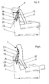
Bei dem in den Figuren 3 und 4 gezeigten Ausführungsbeispiel ist an der Kopfstütze 7 ein erstes Beschlagteil 19 mit seinem einen Ende an einem durch eine Platte 20 verstärkten Bereich der Kopfstütze 7 angelenkt. Das erste Beschlagteil 19 ist starr am Korpus 1 befestigt. An dem durch eine Platte 20 verstärkten Bereich der Kopfstütze 7 ist ein zweites Beschlagteil 18 mit seinem einen Ende angelenkt. Dabei ist der Anlenkpunkt des ersten Beschlagteils 19 vom Anlenkpunkt des zweiten Beschlagteils 18 beabstandet. Das andere Ende des zweiten Beschlagteils 18 ist an dem ersten Ende eines etwa waagerecht angeordneten Hebels 22 (bei 21) angelenkt. Der Hebel 22 ist weiter über seinen Verlauf etwa mittig an das erste Beschlagteil 19 angelenkt (bei 23) und mit seinem zweiten Ende an dem Hilfsrahmen 12 des Rückenlehnteils 6 angelenkt. Die Kopfstütze 7 ist in der Sitzposition nach hinten verschwenkt und übergreift das obere Ende der Rückwand 3. In der Relaxposition ist die Kopfstütze 7 nach vorn hochgeschwenkt und bildet eine Verlängerung des Rückenlehnteils 6.In the embodiment shown in Figures 3 and 4, a first
Bei dem in den Figuren 5 und 6 gezeigten Ausführungsbeispiel ist an der Kopfstütze 7 ein Gestellteil 24 mit einem daran ausgebildeten Bolzen angeordnet. Der Bolzen ist in einer gestellfest am Korpus 1 befestigten Platte 25 mit einem Führungsschlitz 26 geführt. An dem Gestellteil 24 ist das erste Ende eines etwa senkrecht verlaufenden Beschlagteils 27 angelenkt. Das zweite Ende des etwa senkrecht verlaufenden Beschlagteils 27 ist an dem ersten Ende eines Hebels 28 angelenkt. Der Hebel 28 ist am Korpus 1 etwa mittig und an seinem zweiten Ende an dem Hilfsrahmen 12 des Rückenlehnteils 6 angelenkt. Die Kopfstütze 7 ist somit in der Sitzposition nach hinten verschwenkt und übergreift das obere Ende der Rückwand 3. In der Relaxposition ist die Kopfstütze 7 nach vorn hochgeschwenkt und bildet eine Verlängerung des Rückenlehnteils 6.In the embodiment shown in Figures 5 and 6, a
Bei dem in den Figuren 7 und 8 gezeigten Ausführungsbeispiel ist an der Kopfstütze 7 ein Gestellteil in Form einer Platte 29 angeordnet. An der Platte 29 ist das erste Ende eines etwa senkrecht verlaufenden Beschlagteiles 30 (Stellhebel) angelenkt, so dass in diesem Gelenkpunkt eine Schwenkachse (bei 31) für die Kopfstütze 7 gebildet ist. Weiter ist in dem Ausführungsbeispiel an der Platte 29 ein Druck-Zugelement in Form einer Zugstange 32 mit seinem ersten Ende angelenkt. Der Anlenkbereich 31 A hat Abstand von der Gelenkstelle 31. Dabei ist das zweite Ende der Zugstange 32 am Hilfsrahmen 12 des Rückenlehnteils 6 befestigt. Das zweite Ende des etwa senkrecht verlaufenden Beschlagteils 30 ist an Teilen des Korpus 1 angelenkt. Die Kopfstütze 7 ist auch in diesem Ausführungsbeispiel in der Sitzposition nach hinten verschwenkt und übergreift das obere Ende der Rückwand 3. In der Relaxposition ist die Kopfstütze 7 nach vorn hochgeschwenkt und bildet eine Verlängerung des Rückenlehnteils 6.In the embodiment shown in Figures 7 and 8, a frame member in the form of a
Bei den in den Figuren 3 bis 10 gezeigten Ausführungsbeispielen ist das Rückenlehnteil 6 und die Kopfstütze 7 des Sitzmöbels mit einem durchgehenden zusammenhängenden Polster versehen. Das Polster ist insbesondere im Übergangsbereich Rückenlehnteil 6/Kopfstütze 7 scharnierbar ausgebildet und unterstützt die Schwenkbewegung der Kopfstütze 7.In the embodiments shown in Figures 3 to 10, the
In den Figuren 9 und 10 ist ein weiteres Ausführungsbeispiel gezeigt, welches besonders kostengünstig und einfach herzustellen ist. Wie aus den Figuren 9 und 10 ersichtlich, ist an der Kopfstütze 7 rückseitig ein Gestellteil in Form einer Stange 33 angeordnet. Alternativ könnte das Gestellteil auch durch eine Platte gebildet sein. An dem einen Endbereich der Stange 33 ist das erste Ende einer Führungsstange 34 angelenkt (bei 38). Auf der Führungsstange 34 ist eine an dem Hilfsrahmen 12 befestigte Führungshülse 35 aufgeschoben und geführt. Das zweite Ende der Führungsstange 34 ist an dem ersten Ende eines etwa senkrecht verlaufenden Beschlagteils 36 angelenkt. (Stellhebel 36).In the figures 9 and 10, a further embodiment is shown, which is particularly inexpensive and easy to manufacture. As can be seen from FIGS. 9 and 10, a frame part is in the form of a back part on the headrest 7 a
Das zweite Ende 37 des etwa senkrecht verlaufenden Beschlagteils 36 ist am Korpus 1 angelenkt. Dabei ist das Polster des Sitzmöbels zumindest im Übergangsbereich bei 38,39 von dem Rückenlehnteil 6 zur Kopfstütze 7 scharnierbar ausgebildet und dient als Bewegungselement. Die Kopfstütze 7 ist in der Sitzposition nach hinten verschwenkt. In dieser Lage übergreift die Kopfstütze das obere Ende der Rückwand 3 (siehe Figur 9).The
In der in Figur 10 dargestellten Relaxposition des Ausführungsbeispiels ist die Kopfstütze 7 nach vorn hochgeschwenkt und bildet eine Verlängerung des Rückenlehnteils 6. Hierbei bildet das Polster ein wesentliches Bewegungselement.In the relaxed position of the embodiment shown in Figure 10, the
Bei den in den Figuren gezeigten Ausführungsbeispielen wird eine quasi stationäre Schwenkung der Kopfstütze 7 erreicht. Die Kopfstütze 7 folgt bei diesen Lösungen der Verschiebebewegung des Rückenlehnteils 6 nach unten beziehungsweise oben nicht. Bei allen parallelen Lösungen ist es gemeinsam, dass das Rückenlehnteil 6 und das Sitzteil 5 miteinander gekoppelt sind, so dass beim Verschieben des Sitzteiles 5 nach vorne das Rückenlehnteil 6 eine Abwärtsbewegung vollzieht, um von der Sitzposition in die Relaxposition zu wechseln.In the embodiments shown in the figures, a quasi-stationary Pivoting the
Bei allen Ausführungsformen wird erreicht, dass bei durchgehender Polsterung weder in der Sitzposition noch in der Relaxposition Verwerfungen der Polsterung im Bereich des Überganges von der Kopfstütze zum Rückenlehnteil auftreten. Vielmehr wird das Polster in jeder Lage straff gehalten und dient insbesondere bei der Ausführung gemäß Figur 9 und 10 als Stellglied für die Schwenkbewegung der Kopfstütze.In all embodiments it is achieved that in continuous padding neither in the sitting position nor in the relaxed position distortions of the padding in the region of the transition from the headrest to the backrest part occur. Rather, the pad is kept taut in each layer and is used in particular in the embodiment according to Figure 9 and 10 as an actuator for the pivotal movement of the headrest.
Die Erfindung ist nicht auf das Ausführungsbeispiel beschränkt, sondern im Rahmen der Offenbarung vielfach variabel.The invention is not limited to the embodiment, but in the context of the disclosure often variable.
Alle neuen, in der Beschreibung und/oder Zeichnung offenbarten Einzel- und Kombinationsmerkmale werden als erfindungswesentlich angesehen.All new, disclosed in the description and / or drawing single and combination features are considered essential to the invention.
Claims (11)
Applications Claiming Priority (1)
| Application Number | Priority Date | Filing Date | Title |
|---|---|---|---|
| DE202004013904U DE202004013904U1 (en) | 2004-09-03 | 2004-09-03 | seating |
Publications (2)
| Publication Number | Publication Date |
|---|---|
| EP1632152A2 true EP1632152A2 (en) | 2006-03-08 |
| EP1632152A3 EP1632152A3 (en) | 2008-04-23 |
Family
ID=33483538
Family Applications (1)
| Application Number | Title | Priority Date | Filing Date |
|---|---|---|---|
| EP05008467A Withdrawn EP1632152A3 (en) | 2004-09-03 | 2005-04-19 | Seating furniture |
Country Status (4)
| Country | Link |
|---|---|
| US (1) | US7201438B2 (en) |
| EP (1) | EP1632152A3 (en) |
| DE (1) | DE202004013904U1 (en) |
| ZA (1) | ZA200504739B (en) |
Cited By (2)
| Publication number | Priority date | Publication date | Assignee | Title |
|---|---|---|---|---|
| DE102007049118B3 (en) * | 2007-10-12 | 2009-02-05 | Stanzwerk Wetter Sichelschmidt Gmbh & Co. Kg | Seating furniture, has headrest connected with backrest via actuator, and operating handle including end articulated at lengthening piece of guiding arm, where piece is protruded towards coupler via articulating point of arm |
| DE202009000731U1 (en) | 2009-01-22 | 2009-03-26 | Stanzwerk Wetter Sichelschmidt Gmbh & Co. Kg | seating |
Families Citing this family (10)
| Publication number | Priority date | Publication date | Assignee | Title |
|---|---|---|---|---|
| WO2008129567A1 (en) * | 2007-04-18 | 2008-10-30 | Stema S.R.L. | Mechanism for reclining armchairs or sofas |
| US7862110B2 (en) * | 2007-04-20 | 2011-01-04 | L & P Property Management Company | Headrest for recliner chair |
| DE202008016813U1 (en) * | 2008-12-19 | 2009-03-26 | Rolf Benz Ag & Co. Kg | Seating furniture with adjustable headrest |
| US9084708B2 (en) | 2010-12-08 | 2015-07-21 | Broda Enterprises Inc. | Modular chair |
| USD744909S1 (en) * | 2011-06-15 | 2015-12-08 | R82 A/S | Walking frame for disabled |
| USD751468S1 (en) * | 2014-04-01 | 2016-03-15 | Stryker Corporation | Transport apparatus |
| WO2016092249A1 (en) * | 2014-12-11 | 2016-06-16 | Integrated Furniture Technologies Limited | Adjustable furniture |
| US9480336B1 (en) * | 2015-04-15 | 2016-11-01 | American Leather Operations, Llc | Motion furniture with deployable headrest |
| CN209644428U (en) * | 2018-09-29 | 2019-11-19 | 嘉兴礼海电气科技有限公司 | A kind of overturning head rest device no for sofa |
| CN214711596U (en) * | 2020-12-31 | 2021-11-16 | 张孝兆 | Headrest device and seat with same |
Citations (4)
| Publication number | Priority date | Publication date | Assignee | Title |
|---|---|---|---|---|
| DE2401231A1 (en) * | 1973-01-12 | 1974-07-25 | La Z Boy Chair Co | ARMCHAIR WITH ADJUSTABLE BACKREST |
| US3871705A (en) * | 1973-10-23 | 1975-03-18 | Mohasco Ind Inc | Chair with projecting headrest and hardware therefor |
| EP0277870A1 (en) * | 1987-01-23 | 1988-08-10 | Tousalon France S.A. | Operating device for an adjustable chair, seat or couch with a lumbar support |
| US5340191A (en) * | 1993-04-07 | 1994-08-23 | The Lane Company, Inc. | Reclining chair having pop-up headrest |
Family Cites Families (7)
| Publication number | Priority date | Publication date | Assignee | Title |
|---|---|---|---|---|
| US4386803A (en) * | 1981-11-05 | 1983-06-07 | Gilderbloom Clarence W | Motorized reclining chair |
| US4691961A (en) * | 1986-02-14 | 1987-09-08 | Parma Corporation | Recliner with headrest |
| BR8804019A (en) * | 1988-07-29 | 1988-11-16 | Percival Lafer | RECLINING CHAIR |
| US5346277A (en) * | 1992-07-30 | 1994-09-13 | Parma Corporation | Foldable headrest mechanism |
| US5374100A (en) * | 1993-03-12 | 1994-12-20 | Ultra-Mek, Inc. | Adjustable foldable headrest |
| US5310243A (en) * | 1993-03-26 | 1994-05-10 | Dbju, Inc. | Headrest support assembly for recliner chair |
| US5464269A (en) * | 1993-10-12 | 1995-11-07 | Mizelle; Ned W. | Upholstered furniture and movable headrest |
-
2004
- 2004-09-03 DE DE202004013904U patent/DE202004013904U1/en not_active Expired - Lifetime
-
2005
- 2005-04-19 EP EP05008467A patent/EP1632152A3/en not_active Withdrawn
- 2005-08-31 US US11/217,116 patent/US7201438B2/en not_active Expired - Fee Related
-
2006
- 2006-02-10 ZA ZA200504739A patent/ZA200504739B/en unknown
Patent Citations (4)
| Publication number | Priority date | Publication date | Assignee | Title |
|---|---|---|---|---|
| DE2401231A1 (en) * | 1973-01-12 | 1974-07-25 | La Z Boy Chair Co | ARMCHAIR WITH ADJUSTABLE BACKREST |
| US3871705A (en) * | 1973-10-23 | 1975-03-18 | Mohasco Ind Inc | Chair with projecting headrest and hardware therefor |
| EP0277870A1 (en) * | 1987-01-23 | 1988-08-10 | Tousalon France S.A. | Operating device for an adjustable chair, seat or couch with a lumbar support |
| US5340191A (en) * | 1993-04-07 | 1994-08-23 | The Lane Company, Inc. | Reclining chair having pop-up headrest |
Cited By (3)
| Publication number | Priority date | Publication date | Assignee | Title |
|---|---|---|---|---|
| DE102007049118B3 (en) * | 2007-10-12 | 2009-02-05 | Stanzwerk Wetter Sichelschmidt Gmbh & Co. Kg | Seating furniture, has headrest connected with backrest via actuator, and operating handle including end articulated at lengthening piece of guiding arm, where piece is protruded towards coupler via articulating point of arm |
| BE1019598A5 (en) * | 2007-10-12 | 2012-09-04 | Sichelschmidt Stanzwerk | ADJUSTABLE SEAT. |
| DE202009000731U1 (en) | 2009-01-22 | 2009-03-26 | Stanzwerk Wetter Sichelschmidt Gmbh & Co. Kg | seating |
Also Published As
| Publication number | Publication date |
|---|---|
| ZA200504739B (en) | 2006-03-29 |
| EP1632152A3 (en) | 2008-04-23 |
| US7201438B2 (en) | 2007-04-10 |
| DE202004013904U1 (en) | 2004-11-18 |
| US20060049673A1 (en) | 2006-03-09 |
Similar Documents
| Publication | Publication Date | Title |
|---|---|---|
| EP1632152A2 (en) | Seating furniture | |
| DE102010014126B4 (en) | Seating furniture with a seat pivotable in a standing-up assistance position | |
| EP1911371B1 (en) | Seating furniture, in particular an office chair | |
| DE2459109C3 (en) | Hardware linkage for an armchair | |
| DE3817761C2 (en) | ||
| WO2001091614A1 (en) | Chair | |
| WO1980002102A1 (en) | Armchair | |
| DE102007049118B3 (en) | Seating furniture, has headrest connected with backrest via actuator, and operating handle including end articulated at lengthening piece of guiding arm, where piece is protruded towards coupler via articulating point of arm | |
| DE3002032A1 (en) | ADJUSTABLE ARMCHAIR WITH WALL-AVOIDING EFFECT | |
| DE1294618B (en) | Adjustable rocking chair | |
| DE202006005139U1 (en) | Sofa bed has back rest which is mounted on levers, allowing it to be moved to increase or decrease width of seat | |
| DE102006013119A1 (en) | Seat furniture, has guidance operating lever linked or fastened at both side walls of backrest, and connected with control lever, which is arranged at rear side of backrest and controls pivoting of head rest | |
| EP2893844B1 (en) | Seating furniture with head part which can be pivoted using a motor | |
| DE4219599C2 (en) | Synchronizing device for office chairs or the like | |
| DE102006016646B4 (en) | seating | |
| DE202006016889U1 (en) | Chair has reclining back and extending foot rest which are operated by spindle driven by electric motor, nut mounted on this moving lever, on which foot rest is mounted | |
| DE202006006004U1 (en) | Bed frame has back supporting part or component of back supporting part which is connected by coupler with upper side supporting part | |
| EP2111138B1 (en) | Seating furniture comprising a pivotable foot part | |
| DE202006005301U1 (en) | Bed frame has swiveling back rest and thigh support mounted on it, inner ends of which are attached to pivots, space in frame allowing them to be mounted close together | |
| DE202005005928U1 (en) | Armchair has a footrest which is connected to mounting plates on sides of seat by lever system so that it is automatically extended when seat is reclined | |
| DE4236195A1 (en) | Hospital bed with liftable backrest - has lifting which provides sync. displacement of its lower end in direction of head, lifting and displacement provided by leverage of lifting device | |
| DE10044629C2 (en) | Functional fitting for upholstered furniture | |
| DE202009000731U1 (en) | seating | |
| DE2757652A1 (en) | Mounting for chair and foot rest - is adjustable between sitting and reclining position and has metal frame with links | |
| DE202006013897U1 (en) | Seat comprises a connecting rod or hoop which pivots in the fixed rear part of in the fixed armrest part |
Legal Events
| Date | Code | Title | Description |
|---|---|---|---|
| PUAI | Public reference made under article 153(3) epc to a published international application that has entered the european phase |
Free format text: ORIGINAL CODE: 0009012 |
|
| AK | Designated contracting states |
Kind code of ref document: A2 Designated state(s): AT BE BG CH CY CZ DE DK EE ES FI FR GB GR HU IE IS IT LI LT LU MC NL PL PT RO SE SI SK TR |
|
| AX | Request for extension of the european patent |
Extension state: AL BA HR LV MK YU |
|
| PUAL | Search report despatched |
Free format text: ORIGINAL CODE: 0009013 |
|
| AK | Designated contracting states |
Kind code of ref document: A3 Designated state(s): AT BE BG CH CY CZ DE DK EE ES FI FR GB GR HU IE IS IT LI LT LU MC NL PL PT RO SE SI SK TR |
|
| AX | Request for extension of the european patent |
Extension state: AL BA HR LV MK YU |
|
| AKX | Designation fees paid | ||
| STAA | Information on the status of an ep patent application or granted ep patent |
Free format text: STATUS: THE APPLICATION IS DEEMED TO BE WITHDRAWN |
|
| 18D | Application deemed to be withdrawn |
Effective date: 20081024 |
|
| REG | Reference to a national code |
Ref country code: DE Ref legal event code: 8566 |