EP0343958B1 - Elektronisches Musikinstrument - Google Patents
Elektronisches Musikinstrument Download PDFInfo
- Publication number
- EP0343958B1 EP0343958B1 EP89305251A EP89305251A EP0343958B1 EP 0343958 B1 EP0343958 B1 EP 0343958B1 EP 89305251 A EP89305251 A EP 89305251A EP 89305251 A EP89305251 A EP 89305251A EP 0343958 B1 EP0343958 B1 EP 0343958B1
- Authority
- EP
- European Patent Office
- Prior art keywords
- tone
- generating
- musical
- key
- message
- Prior art date
- Legal status (The legal status is an assumption and is not a legal conclusion. Google has not performed a legal analysis and makes no representation as to the accuracy of the status listed.)
- Expired - Lifetime
Links
- 239000000470 constituent Substances 0.000 claims description 109
- 230000008859 change Effects 0.000 claims description 12
- 239000011295 pitch Substances 0.000 claims description 12
- 230000033764 rhythmic process Effects 0.000 claims description 6
- 230000003247 decreasing effect Effects 0.000 claims description 3
- 238000012545 processing Methods 0.000 description 54
- 238000000034 method Methods 0.000 description 44
- 230000008569 process Effects 0.000 description 39
- 230000004044 response Effects 0.000 description 20
- 238000013016 damping Methods 0.000 description 12
- 230000000994 depressogenic effect Effects 0.000 description 11
- 238000006243 chemical reaction Methods 0.000 description 9
- 230000000977 initiatory effect Effects 0.000 description 9
- FRPGHNBHIDMQGT-UHFFFAOYSA-N 2,5-Dimethyl-4-(1-pyrrolidinyl)-3(2H)-furanone Chemical compound O=C1C(C)OC(C)=C1N1CCCC1 FRPGHNBHIDMQGT-UHFFFAOYSA-N 0.000 description 7
- 101001003569 Homo sapiens LIM domain only protein 3 Proteins 0.000 description 7
- 101000639972 Homo sapiens Sodium-dependent dopamine transporter Proteins 0.000 description 7
- 102100026460 LIM domain only protein 3 Human genes 0.000 description 7
- 239000002131 composite material Substances 0.000 description 4
- 238000004364 calculation method Methods 0.000 description 3
- 238000001514 detection method Methods 0.000 description 3
- 230000000694 effects Effects 0.000 description 3
- 238000004088 simulation Methods 0.000 description 3
- 238000004891 communication Methods 0.000 description 2
- 238000005516 engineering process Methods 0.000 description 2
- 238000004519 manufacturing process Methods 0.000 description 2
- 230000004048 modification Effects 0.000 description 2
- 238000012986 modification Methods 0.000 description 2
- OZAIFHULBGXAKX-UHFFFAOYSA-N 2-(2-cyanopropan-2-yldiazenyl)-2-methylpropanenitrile Chemical compound N#CC(C)(C)N=NC(C)(C)C#N OZAIFHULBGXAKX-UHFFFAOYSA-N 0.000 description 1
- 240000006829 Ficus sundaica Species 0.000 description 1
- 241000251131 Sphyrna Species 0.000 description 1
- 230000004913 activation Effects 0.000 description 1
- 230000004075 alteration Effects 0.000 description 1
- 238000010586 diagram Methods 0.000 description 1
- 230000006870 function Effects 0.000 description 1
- 230000005923 long-lasting effect Effects 0.000 description 1
- 230000007246 mechanism Effects 0.000 description 1
- 239000012528 membrane Substances 0.000 description 1
- 230000015654 memory Effects 0.000 description 1
- 238000010606 normalization Methods 0.000 description 1
- 230000003936 working memory Effects 0.000 description 1
Images


Classifications
-
- G—PHYSICS
- G10—MUSICAL INSTRUMENTS; ACOUSTICS
- G10H—ELECTROPHONIC MUSICAL INSTRUMENTS; INSTRUMENTS IN WHICH THE TONES ARE GENERATED BY ELECTROMECHANICAL MEANS OR ELECTRONIC GENERATORS, OR IN WHICH THE TONES ARE SYNTHESISED FROM A DATA STORE
- G10H1/00—Details of electrophonic musical instruments
- G10H1/02—Means for controlling the tone frequencies, e.g. attack or decay; Means for producing special musical effects, e.g. vibratos or glissandos
- G10H1/04—Means for controlling the tone frequencies, e.g. attack or decay; Means for producing special musical effects, e.g. vibratos or glissandos by additional modulation
- G10H1/053—Means for controlling the tone frequencies, e.g. attack or decay; Means for producing special musical effects, e.g. vibratos or glissandos by additional modulation during execution only
- G10H1/057—Means for controlling the tone frequencies, e.g. attack or decay; Means for producing special musical effects, e.g. vibratos or glissandos by additional modulation during execution only by envelope-forming circuits
-
- G—PHYSICS
- G10—MUSICAL INSTRUMENTS; ACOUSTICS
- G10H—ELECTROPHONIC MUSICAL INSTRUMENTS; INSTRUMENTS IN WHICH THE TONES ARE GENERATED BY ELECTROMECHANICAL MEANS OR ELECTRONIC GENERATORS, OR IN WHICH THE TONES ARE SYNTHESISED FROM A DATA STORE
- G10H1/00—Details of electrophonic musical instruments
- G10H1/18—Selecting circuits
Definitions
- the invention relates to systems of electronic musical instruments, such as an electronic keyboard instrument, an electronic drum apparatus, a rhythm apparatus, an automatically performing apparatus, an automatically accompanying apparatus, or the like.
- the invention relates to a technology by which sound-generating units in such electronic musical instruments are caused in sequence to generate musical tones, as well as to a further technology for processing a succeeding additional "note-on" signal that is input to said electronic musical instruments after the preceding same musical note has been input thereto so that the same musical tones are superposed one on another.
- Each of the musical tone-generating apparata that are currently known has only a limited number of, for instance sixteen, tone generators. Accordingly, in such electronic musical instruments of this type (JP-A-62208098), there will occur a shortage of generated musical tones in case of simultaneously playing many sounds at the same time while a hold pedal is pressed down. In other words, some tones are not generated, or unwantedly decay or die away quickly in such a case.
- the so-called musical instrument digital interface is widely employed in electronic musical instruments so as to transmit tone-generating control data between apparatus units included therein.
- the MIDI has therefore given rise to a new system of electronic musical instruments such that a tone data-generating apparatus is coupled with a plurality of tone-generating apparata by means of the MIDI.
- some additional tone-generating apparata can be added to the existing ones and connected by the MIDI to the tone data-generating apparatus in order that a possible insufficiency in the number of sound sources may be complemented.
- EP-A-0 030 034 describes a system in which those decaying notes which have reached the lowest level (in volume) are replaced by the newly sounded notes.
- the notes corresponding to the even-numbered note-on signals take place more frequently or less frequently than the notes corresponding to the odd-numbered note-on signals.
- one of the tone-generating apparata is likely to be activated more times to produce more musical tones than the other whereby a balance of activation times between the tone-generating apparata is hardly ensured.
- each tone is generated by striking a tone-generating body (string, diaphragm or the like). Accordingly, when the tone-generating body which has generated a musical tone generates the same musical tone again in a superposed manner, the previously generated tone is weakened when the tone-generating body is struck again and a newly generated tone is added.
- This problem may be eliminated by the system in which, as also referred to above, the tone generated by the previous note-on signal is damped upon initiation of the generation of a tone caused by the subsequent note-on signal.
- the tone is quickly weakened to an undesirable degree when the second musical tone taking place based on the subsequent note-on signal superposed on the first musical tone taking place based on the previous note-on signal has a smaller generated volume (amplitude) than the earlier first tone.
- the system in accordance with the invention comprising: at least one performance message-generating apparatus; and a plurality of sound-generating units each adapted to receive performance-controlling messages from the performance message-generating apparatus; is characterised in that each of said sound-generating units comprises: recording means for recording preferential orders which determine a sequential order by which said sound-generating unit receives the performance-controlling messages, selecting means for selecting the performance-controlling messages to receive same in accordance with the preferential orders recorded in the recording means; and tone-generating means for generating musical tones based on the performance-controlling messages which have been received by the selecting means.
- the sound-generating units are caused to generate sounds in accordance with the selectively received performance-controlling messages which are given to said units according to the preferential orders arranged in circulative sequence. Therefore, a good balance is provided between the sound-generating units because their opportunities to generate sounds are well equalized without any marked unevenness in their times of the generating of sounds.
- each sound-generating unit has musical tone-generating channels and causing same to generate said musical tones based on the performance-controlling messages that have been received by the selecting means; and each sound-generating unit firstly comprises first detecting means for detecting whether or not a second musical tone based on a new note-on message and a first or previous musical tone which has been already assigned by a previous note-on message to the musical tone-generating channels are the same musical tone; second detecting means for detecting the volume of the first musical tone to be generated or a value equivalent to that generated volume which was assigned to the tone-generating channels in the tone-generating means and is being generated based on the previous note-on message at the instant when the new note-on message to generate the same tone is received; calculating means for calculating a residual generated volume or a value equivalent thereto, based on the generated volume or a value equivalent thereto which is detected by the second detecting means; and changing
- the sound-generating units are equalized as to their sound-generating times or frequencies, and further, the generated volume of the tone based on the previous note-on message is changed to the residual generated volume or said value equivalent thereto so that a change in volume is reproduced to realize an attenuation based on the tone which corresponds to the new note-on message.
- the second detecting means may be a detecting means for detecting the generated volume or the value equivalent thereto, based on a constituent tone mainly constituting a continuing portion of a musical tone to be generated to give a feeling of volume.
- the changing means may be a changing means for altering an envelope of the first or previous musical tone, which has been already assigned by the previous note-on message to the tone-generating channels in its tone-generating means, to thereby change the generated volume of the first musical tone or the value equivalent thereto into the residual generated volume or the value equivalent thereto.
- the first detecting means may be such that it either simulates an envelope waveform of the musical tone so as to detect the aforementioned generated volume or the value equivalent thereto, or detects said generated volume or the equivalent thereto of the musical tone on the basis of an envelope level.
- the systems according to the invention described hereinbefore may further comprise shifting means for shifting in a circulative manner the preferential orders that are stored by the recording means based on the performance-controlling messages, on the basis of an initial information regarding initial preferential orders and a total number of the sound-generating units.
- Said system may further comprise recovering means for recovering the notes assigned to the tone-generating channels from their note-off states to the note-on states in case where the first detecting means detects a state that the note specified by the previous note-on message has already assigned to the tone-generating channels in its tone-generating means the same musical tone as that specified by the new note-on message.
- the aforementioned performance message-generating apparatus may be a mother keyboard or a sequencer.
- the electronic musical instrument system may be one provided with a keyboard, or a system of electronic drum apparatuses, a system of rhythm machines, a system of automatically performing apparatuses, or a system of automatically accompanying apparatuses.
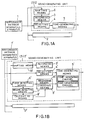
- Fig.1A illustrates schematically the musical instrument system as claimed in claim 1 and Fig.1B similarly illustrates the system as claimed in claim 2.
- Fig.2 illustrates an outline of a musical instrument system comprising a keyboard apparatus 11 as an example of performance message-generating apparatus, which keyboard apparatus 11 is connected by MIDI 12 to respective sound-generating units S.
- Musical tone signals generated in the sound-generating units S are summed up and then fed through an amplifier 13 to a loud speaker 14 to thereby produce audible sounds.
- Fig.3 shows in outline one of the sound-generating units S.
- an input interface 20, qualified as a MIDI receives data as performance-controlling messages in the invention, and delivers same to a signal-detecting circuit 21 to be detected thereby.
- a plurality of data as outputs from the signal-detecting circuit 21 are sorted to select some data necessary for the sound-generating units S.
- Fig.4 illustrates that each of the received data RCVD which are received by the signal-detecting circuit 21 comprises three bytes consisting of a first byte STAT, a second byte DAT1 and a third byte DAT2. These data are stored in a buffer included in the signal-detecting circuit 21. The thus stored data are charged to a microcomputer 22 through a bus 23 together with the total number of the received data BSTN under control by the microcomputer.
- the data which were referred to above as the necessary data for the sound-generating units S include, as shown in Fig.4, key-press data, key-off data, as well as damper data that relate to a damper which is pressed down to inhibit a damping processing. This damping processing would otherwise accelerate the damping of sounds, therefore the damper data are needed to prolong the period of decay.
- the buffer may further store, if necessary, after-touch data, program-changing data, control-changing data, mode-message data, and/or system-exclusive data if they are selected.
- the key-press and the key-off data as well as the damper-on and the damper-off data are binary coded.
- Each of the first bytes STAT of those data comprises four leading bits and four trailing bits “nnnn", “n” indicating signal-receiving channels. Seven trailing digits “kkkkkkk” in the second bytes DAT1 indicate ordinal numbers corresponding to key codes whereas the other seven trailing digits “vvvvvv” in the third bytes DAT2 indicate velocities. ( These components of data will hereinafter be simply called “n”, “k” and “v” if decimals are adopted to indicate them, and “n” may vary from 0 (zero) to 15 while “k” and “v” fall within a range of 0 (zero) to 127.
- the signal-detecting circuit 21 in the sound generating units S is, for the sake of convenience, regarded in this description to be capable of receiving signals through the signal-receiving channels 0 to 7 only, and incapable of receiving them through channels 8 to 15.
- the signal-receiving channels 0 to 7 are assigned to eight timbres or musical tones such as those of the piano, the harpsichord and so on.
- An operator of this system is instructed to make previous settings of a total-number switch TOTLSW 24A and a preferential-order switch PRIOSW 24B, these switches constituting a components-in-total switch 24.
- the preset states of the switches TOTLSW 24A and PRIOSW 24B are detected by a switch-detecting circuit 25 so as to be charged to the microcomputer 22 as an incorporated-components data TOTL and as initial data PRIO of the preferential orders.
- the operator can employ a total number of the sound generating units S as such a data TOTL that is to be set on the switch TOTLSW 24A.
- the switch PRIOSW 24B can make use of the switch PRIOSW 24B to assign numerals from "1" to a higher ordinal to the respective sound generating units S, as the initial data of the preferential orders.
- the higher ordinal corresponds to the incorporated-components data TOTL, and assigning of such numerals has to be carried out sequentially not to involve any overlapping or doubling of the numerals between any two or more such units S.
- the microcomputer 22 is further charged with manually operable member data MNPh through a manually operable member detecting circuit 27, the data MNPh representing operated states of a group of manually operable members 26.
- These members 26 serve the purpose of switching over or adjusting the timbres and the generated volume of each musical tone. It is to be noted that all of the aforementioned data, namely the incorporated-components data TOTL, the initial data PRIO of preferential orders, and the manually operable member data MNPh, are those which indicate the states of related parts or components at the moment when they are charged to the microcomputer 22 for control of the system thereby.
- the microcomputer 22 itself comprises a central processing unit (CPU) 22A executing the predetermined programs, a read only memory (ROM) 22B storing the programs, a random access memory (RAM) 22C used as a working memory required for executing the programs and also as registers allotted to the received data RCVD, the incorporated-components data TOTL, the initial data PRIO of preferential orders, and the manually operable member data MNPh.
- the microcomputer further comprises a timer circuit 22D consisting of a group of timers or clocks that determine the times or moments during execution of the programs.
- a tone-generating circuit 28 having sixteen (16) tone-generating channels in the first embodiment is activated and controlled by executing the aforementioned programs by means of the received data RCVD, incorporated-components data TOTL, the initial data PRIO of preferential orders, and the manually operable member data MNPh. Desirable musical tone signals are produced respectively by the thus determined and assigned tone-generating channels.
- Step H The damping processing subroutine (Step H) will now be described in detail with reference to Fig. 8 in a step-by-step manner.
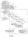
- Step N The preferential order-shifting subroutine ( Step N ) will now be described in detail with reference to Fig. 9 in a step-by-step manner.
- the subroutine just described above is so designed that the preferential data PRI are incrementally increased each time the key-press data is received, whereby any preferential data PRI which has exceeded the incorporated-components data TOTL is reset at "1".
- the preferential order data PRI which are assigned thereto change their values upon each receipt of key-press data as shown in Fig.10. Only such a sound-generating unit S for which the value of preferential order data PRI is set at "1" at a given instant does generate sound on the basis of judgment that the key-press data received at that instant is valid.
- all of the incorporated sound-generating units S can generate sounds in turn such that none of them is allowed to generate sound more frequently than the remaining ones do, thus equalizing all the sound-generating units S with respect to the number of sounds generated.
- the number of sounds actually generated at each instant is kept equal to the number of incorporated sound-generating units S, no matter what key codes may be received, thus providing a sufficient effect of increasing the effective sources of sounds.
- the initial values PRIO of preferential orders may be reset as the preferential order data PRI onto the registers PRIOR in the event that all the keys were released.
- This arrangement will be useful for re-normalization of preferential orders which might become out of order occasionally due to alterations made by a user of this system on the incorporated-components data TOTL or on the initial values PRIO of preferential orders.
- the incorporated-components data TOTL as well as the initial values PRIO of preferential orders may be input to and written into the microcomputer 22 by means of the input interface 20 without using the components-in-total switch 24.
- the so-called daisy chain may be employed to establish a mutual communication link between the incorporated sound-generating units S which are connected to each other by means of the MIDI.
- a data relating to such connections may, in this communication link, be sent successively from one to another sound-generating unit S so as to enable an automatic detection of the incorporated-components data TOTL by themselves thereby to set up automatically the data TOTL and the initial values PRIO of preferential orders.
- the signal-receiving channel numbers "n" are predetermined for respective timbres in the first embodiment, said numbers "n” may be assignable to the timbres at user's discretion. And in such a case, the same signal-receiving channel may be allotted to each sound-generating unit S as to one and the same timbre. Another total number of timbres may be adopted instead of eight (8) set up beforehand in the first embodiment.
- the user may choose any initial value PRIO of preferential orders to activate from time to time the sound generating units whose preferential order data PRI is judged to correspond to the chosen value PRIO.
- All of the preferential order data PRI of all the sound-generating units S should, in such a case, be selected beforehand such that they are cleared up at the same time when the power supply is turned on or all the keys are released.
- the initial values PRIO may be set up mechanically, for instance by means of a rotary switch or anything else, instead of charging them to the RAM 22C to be stored therein.
- the system in the first embodiment comprises merely such sound-generating units S that cannot receive the signals from the signal-receiving channels No. 8 to No.15 but can receive those from the channels No.0 to No. 7.
- a group "A" consisting of three sound generating units S may be assigned to the signal-receiving channels No.0 to No.7 whereas another group "B" consisting of the other three sound-generating units S′ are assigned to the channels No.8 to No.15.
- numeral "3" as the incorporated-components data TOTL together with other numerals "1", “2" and “3" as the sequential initial values PRIO of the preferential orders are allotted to the former group "A" of the units S.
- allotted to the latter group "B” of the units S′ are similar initial values PRIO of preferential orders, whereby note-on messages to the signal-receiving channels No.0 to No.7 cause the group "A" of sound-generating units S to generate sounds sequentially while the other note-on messages to the channels No.8 to No.15 causing the group "B" of the sound-generating units S′ to generate sounds.
- the first invention is applied to the first embodiment in which a musical tone-generating circuit is installed in each sound generating unit.
- the systems may be modified in such a manner that the performance controlling messages are selected to be supplied to a plurality of outside musical tone-generating circuits.
- This embodiment is adapted to the processing of consecutive depressions of one and the same key in such a system as in the first embodiment in which, as described hereinbefore, a plurality of sound-generating units are incorporated in combination to increase the total number of generated sounds per unit period of time.
- the consecutive depressions just referred to above mean that a key is depressed again to generate a new key-press data for a musical tone or sound in order to superpose this sound upon an old sound that has been and still being generated according to an old key-press data by a previous depression of the same key.
- the same signs, numerals or names as those in the first embodiment denote here the same steps, parts or members as those in the first embodiment, and only such features that differ from those in the first embodiment are explained to avoid redundancy of description.
- the second embodiment relates to such sound-generating units S which generate sounds of a decaying type ( percussive type ).
- a scheme of the sound generating units S in this second embodiment is also given in Fig. 2 and thus is of almost the same nature as is those in the first embodiment. However it differs from those in the first embodiment in that a tone-generating circuit 28 has thirty two (32) tone-generating channels.
- each musical tone or sound generated in the second embodiment is composed, as is a sound generated by the piano, of (a) a first constituent tone A and (b) a second constituent tone (B) following the first constituent tone A.
- the first constituent tone A mainly corresponds to an initiation part of the tone (i.e., an attack part "A" plus a decay part "B" in ADSR representation as shown in Fig. 7 ), the initiation part composed of a key-hammering sound and a string-striking sound which is generated immediately after the striking of a string and has a higher content of harmonic components.
- the second constituent tone B mentioned above mainly corresponds to a continuing part (i.e., a sustain part "S" plus a release part "R” ) which gives a feeling of generated volume of the tone, and consists of a string sound which has a lower content of harmonic components and a lesser degree of change in timbre. It is also assumed in the second embodiment that, in order to produce each musical tone signal, the first constituent tone A and the second constituent tone B are respectively generated in different tone-generating channels.
- the tone generating circuit 28 comprises thirty two (32) tone-generating channels wherein a first and a second channel constitute a group, a third and a fourth channel constitute another group, and so on ---, then a thirty first and a thirty second channel constitute a still further group.
- Each of the tone-generating channels carrying even ordinal numbers is assigned to the first constituent tones whereas each of the tone-generating channels carrying odd ordinal numbers is assigned to the second constituent tones so that they respectively produce musical tone signals.
- Each of the tone-generating units S constructed as above in the second embodiment executes a basic program as represented by a flow-chart shown in Fig. 11. Differences between each step in the second embodiment and each corresponding step in the first embodiment will now be explained in detail.
- Step F′ In addition to the procedure I) of Step F in the first embodiment, calculated and produced here based on a group of parameters GTEm(n) relating to generation of musical tones is a first variation rate RTS which indicates minus variations per unit time in changing the envelopes.
- the first variation rate RTS is also one of the envelope parameters and is set up for each envelope waveform producing channel. Therefore, a register RTSR is provided for each envelope wave-form producing channel in order that the first variation rate RTS is written into and read from the register RTSR.
- Attack levels LATK are produced by means of a conversion table which has been stored in a ROM 22B corresponding to and based on a touch-response datum-attack level conversion graph shown in Fig. 12 instead of that shown in Fig. 6.
- Step K′ This step differs from Step K in that a content of a register BCHR is cleared so that assigned-channel numbers BCH in this register are reset at their initial states, indicating no channel numbers assigned, before the decision in Step K is made.
- Step L′ A difference between this step and Step L in the first embodiment is as follows.
- Assignment to musical tone-generating channels is performed similarly to that in the fist embodiment but to the groups respectively consisting of: the first and the second channels; the third and the fourth channels; -----; and then the thirty-first and the thirty-second channels.
- the assignment comprises the writing of said first variation rates RTS into the register RTSR in addition to the procedures of Step L in the first embodiment. Commands are given to each group of the tone-generating channels to commence generation of musical tones, and the channel numbers to which the second constituent tones B were assigned are, as the assigned-channel numbers BCH, written into the register BCHR.
- Step N′ reset are those timers TST which count up time lapses are the assignment of musical tones are reset, the timers being written into registers TSTR which are installed within a timer circuit 22D according to the musical tone-allocating channels. Then, the process goes to Step N′.
- Step M′ This step is identical with Step M in the first embodiment.
- Step N′ Although the content itself of this step is identical with the preferential order-shifting subroutine in Step N of the first embodiment, the process in this second embodiment goes to Step O after completion of Step N′.
- Step O the consecutive-strike detecting routine
- the detecting of consecutive strikes is performed as to the second constituent tones B and by searching musical tone-generating channels which are actually generating musical tones caused by the same key.
- a search is made along all the tone-generating channels, by means of the second constituent tone B, for a musical tone-generating channel which is generating an effective tone and which corresponds to the same timbre which has been assigned to the same signal-receiving channel, and the channel number of that musical tone-generating channel is written into the register AOCH(e)R as the channel number AOCH(e) of the old key-press, and the consecutive-strike detecting flag DMPF is set to "1" showing that the consecutive strikes have been and are being detected.
- tone-generating channel that corresponds to a tone generation of a shortened duration due to the command which has ordered an initiation of the accelerated attenuation in the consecutive-strike processing, is excluded from the tone-generating channels to be treated as above.
- Step Q the consecutive-strike processing routine
- Fig.14 which is made up of Figs. 14A and 14B.
- the second constituent tones B of the old key-presses are assigned to such tone-generating channels which are to be treated by this consecutive-strike processing routine, and which have been detected in the consecutive-strike detecting routine (Step O) and have the channel numbers AOCH(e) of old key-presses written into the register AOCH(e)R.
- the following processing relates to registers which are installed for the second constituent tones B of old key-presses and which correspond to those tone-generating channels which bear the channel numbers AOCH(e) written in the aforementioned registers AOCH(e)R.
- KD 0.9 is employed to simplify the processing.
- the above-described consecutive-strike processing routine is such that the envelope waveform is simulated as to the second constituent tone B of the old key-press and the residual generated volume WOL thereof is calculated so that the envelope of said second constituent tone B is changed, corresponding to said residual generated volume.
- the principle of said routine resides in a processing in which the second constituent tone B produced by a key is used to search for a musical tone-generating channel which is actually generating a musical tone based upon the same key, whereby a consecutive strike of the key is detected to change the envelope.
- the predetermined first variation rate RTS is used to avoid an intricacy of description. It is however more desirable to calculate and determine such a rate that the envelope comes to the next break instant LBP after the time lapse of T1 ( see Step Q-8 ).
- the musical tone is generated in a manner as shown in Fig. 17 in a case wherein the envelope level WLEV of the changed second constituent tone B of old key-press is not larger than the instantaneous envelope level LEV.
- the musical tone will be generated in a manner as shown in Fig. 18 in a case wherein the envelope level WLEV of the changed second constituent tone B of old key-press is larger than the instantaneous envelope level LEV.
- Figs. 17 and 18 there is shown a system in which a musical tone based on a new key-depression is generated by one sound generating unit S that is combined with the other sound generating unit S which has been generating a preceding musical tone.
- a second constituent tone B of the new key-depression is not illustrated in Fig. 18 in order to avoid intricacy.
- the rectangular waves at the bottoms in Figs. 17 and 18 denote the key-press and the key-off operations performed on the same key to provide the previous and the new key-depressions.
- the steps may be omitted which would otherwise be needed when the damping processing is not inhibited due to the damper state flag FCDS(n) indicating "0" to show that the damper pedal is not depressed ( i. e., Damper OFF ) in the decision at Step Q-3.
- the Steps Q-4 to Q-7 may be omitted before the process goes to Step Q-20.
- the treatment for changing the residual generated volume may be executed whatever position the damper pedal may be in. In this case, the process is caused to go to Step Q-8 directly from Step Q-2 thereby by-passing Steps Q-3 to Q-7.
- the musical tones generated according to the second embodiment have, as illustrated in Fig. 19, a composite waveform which is integrated from a waveform of the first constituent tone A and a waveform of the second constituent tone B.
- Fig. 20 gives a logarithmic representation of these waveforms wherein the envelope waveform of the second constituent tone B has a constant rate of change per unit time in the course of time, on and after the decay part "D". Therefore, the same key-presses are deemed to provide such second constituent tones B which have envelope waveforms similar to each other in their shapes on and after said decay part "D".
- the second embodiment of the invention employs, as described hereinbefore, the pairs of musical tone-generating channels, each of the pairs comprising one tone-generating channel assigned to the first constituent tone A and the other assigned to the second constituent tone B. But, such pairs have not necessarily to be employed, and instead said tones can be assigned separately to non-paired tone-generating channels since the channels assigned to the tone A are freed earlier than the other channels assigned to the tone B, as apparent from Fig. 20. Such a system will make it possible to utilize more effectively the musical tone-generating channels.
- All the sound generating units S may, in such a case, be set to an "Omni-Mode-ON" as defined in the MIDI standards wherein all the data ( performance controlling messages ) are read to sequentially generate musical tones each time the keys are depressed while the preferential orders are concurrently changed. Also, there may be employed some converting apparatuses of such a kind that they respectively and exclusively receive the data corresponding to predetermined signal-receiving channels in order to convert the data, before transmitting them to said sound-generating units S, into those which do not include any informations relating to said signal-receiving channels. The sound-generating units S in such a case are therefore controlled to generate sounds by such data lacking the informations relating to the signal-receiving channels.
- the variety in tone quality or timbre of the continuing portion of the musical tone generated is enriched.
- this portion is composed of second constituent tones B1 and B2.
- the second constituent tone B1 higher harmonic components of the continuing portion at a heavy strike are strong and the envelope is relatively short.
- higher harmonic components of the continuing portion at a light strike are weak and the envelope is relatively long, as will be explained below.
- the musical tone-generating circuit 28 is composed of forty-eight musical tone-generating channels from a first channel to a forty-eighth channel.
- the first channel to the third channel, the fourth channel to the sixth channel, .... , the forty-sixth channel to the forty-eighth channel form combinations (trios) generating desired musical tones, respectively.
- the second constituent tone B2 is assigned to the first channel, the fourth channel, Vietnamese
- the second constituent tone B2 is assigned to the second channel
- the first constituent tone A is assigned to the third channel, the sixth channel, .... , to produce musical tone-signals, respectively.
- Consecutive strikes of one key are detected by searching for a musical tone-generating channel which is actually generating the second constituent tone B2 caused by the same key.
- the envelopes are changed, based on the sum of generated volumes of the second constituent tones B1 and B2.
- "3" instead of “2” is added to the number of loops "i" in the consecutive-strike detecting routine at Step O-3.
- each tone-generating channel produces an integral musical tone which is not divided into such a first and a second constituent tones A and B as in the second embodiment.
- musical tones generated here have, as illustrated in Fig. 19, a composite waveform which is integrated from a waveform of the first constituent tone A and a waveform of the second constituent tone B.
- a difference from the second embodiment is that "1" is added the number of loops "i” in place of adding "2" thereto in Step O-3 of the consecutive-strike detecting routine.
- the generated volume WOL of of the second constituent tone B to be generated by the old key-press is calculated by adding the envelope level of the first constituent tone A to an evaluated multiple of the envelope level of the second constituent tone B.
- Said envelope level of the tone A is obtained from the envelope level LEV of a musical tone (composite tone) which is to be generated here, by making use of a conversion table or the like which corresponds to the envelope waveform graph given in Fig.19.
- Said evaluated multiple is obtained by multiplying the residual factor KD by the further envelope level of the second constituent B, the further envelope level in turn being also obtained from said envelope level LEV by using the conversion table in the same manner as just described above.
- the generated volume WOL of the second constituent tone B to be generated by the old key-press may be replaced by the envelope level LEV of the musical tone ( composite tone ) generated.
- the tone of the initial portion and the tone of the continuing portion are contained at different ratios in the first and the second constituent tones A and B, instead of composing a musical tone from said first and second tones per se.
- a musical tone generated as shown in Fig. 22 consists of first and second constituent tones A′ and B′.
- the first constituent tone A′ which is not varied excessively in tone quality by the strength of touch and constitutes mainly the initial portion of a light key-depression, contains a small quantity of higher harmonic components and gives a round feeling.
- the second constituent tone B′ is large at a heavy touch and constitutes mainly the continuing portion of a heavy key-depression which, in the case of a piano, contains a large quantity of higher harmonic components and gives a hard feeling.
- Fig. 23 shows a touch response data KTD-attack level LATK giving a relationship between the touch response data KTD and the attack level LATK, which relationship is equivalent to that given in Fig. 12. Accordingly, the constituent tone B′ is not generated at a light key-depression, and the first constituent tone A′ dominates the musical tone.
- Step Q-8 of the consecutive strike processing routine the generated volume WOL to be generated by the old key-press is obtained by adding such a generated volume of the first constituent tone A′ to such a generated volume of the tone B′ as respectively described in the Modified Example 2.
- the ratio of one constituent tone to the other constituent tone is variable so that the resulting musical tone also may be varied.
- the sounds of decaying or percussive types may include of course those sounds such as drumbeats which are generated by consecutively striking one and the same tone-generating means (e.g., membrane or other struck surface ), in addition to those generated by the keyboard apparatus.
- the present invention is applicable to the processing in the case wherein the musical tone are generated by the manually operable members, for instance the so-called key switch or the like so as to be superposed one on another, in such a manner as in an electronic drum machine system, a rhythm machine system or the like.
- the musical tone are generated by the manually operable members, for instance the so-called key switch or the like so as to be superposed one on another, in such a manner as in an electronic drum machine system, a rhythm machine system or the like.
- it is also possible to enhance the performability for example by conducting quick consecutive strikes or beats, if the same musical tone is assigned to two or more manually operable members so that said same musical tone is generated corresponding to the alternatively repeated operations of said members.
- the present invention is applicable also to a performing apparatus system such as a rhythm machine system or an automatic performing or accompanying apparatus system which can store or program performance, automatically perform or automatically accompany wherein the same musical note is repeated in a superposed manner, if the key-press/off information generated by key-press/off operations in the embodiments are converted into such key-press/off information or equivalent thereto as generated in the performing apparatus just described above, or are changed into other information corresponding to processings peculiar to the performing apparatus just described above.
- a performing apparatus system such as a rhythm machine system or an automatic performing or accompanying apparatus system which can store or program performance, automatically perform or automatically accompany wherein the same musical note is repeated in a superposed manner
- the audio system i.e., the amplifier 13 and the loud-speaker 14
- the audio system was described as a single system adapted to integrally output the inputs from the combined sound-generating units S and S′
- a plurality of audio systems which comprise loud-speakers spaced apart from each, other whereby sounds are emitted in a flip-flop like manner from sound sources positioned at different locations each time the key is depressed, thus giving a peculiar auditory effect.
- the data of preferential orders may be divided into groups separately supplied to each incorporated signal-receiving channels, i. e., timbres.
- the performance message generating apparatus may be a keyboard apparatus (the so-called “mother keyboard”) lacking sound generating units, the manually operable members being actually operated by a user to generate performance messages in the electronic drum apparatus or rhythm machine, and the sequencer or the likes which automatically generate performance messages for the automatic performing or accompanying apparatuses.
- a sound generating unit which has its own keyboard part integral therewith though the sound generating units exemplified in the embodiments do not have such an keyboard part integral therewith.
- the performance messages produced in the keyboard part may be transmitted to an outside sound generating unit in order to generate sounds besides those generated by the internal sound-generating units so that the total number of sound sources is increased.
- All of the registers used in each embodiment are installed in areas assigned notionally to the RAM 22C of the microcomputer 22 as described above.
Landscapes
- Physics & Mathematics (AREA)
- Engineering & Computer Science (AREA)
- Acoustics & Sound (AREA)
- Multimedia (AREA)
- Electrophonic Musical Instruments (AREA)
Claims (15)
- Elektronisches Musikinstrumentensystem, mit mindestens einer Vorrichtung (1) zum Erzeugen von Vorführungsmeldungen und einer Vielzahl von tonerzeugenden Einheiten (2), die jeweils zum Empfang von vorführungsteuernden Meldungen von der Vorrichtung (1) zur Erzeugung von Vorführungsmeldungen ausgebildet sind, dadurch gekennzeichnet, daß jede der tonerzeugenden Einheiten (2) Aufzeichnungsmittel (3) zur Aufzeichnung von bevorzugten Reihenfolgen, die eine sequentielle Reihenfolge bestimmen, in der die tonerzeugende Einheit (2) die vorführungssteuernden Meldungen empfängt, Auswahlmittel (4) zum Auswählen der vorführungssteuernden Meldungen zu ihrem Empfang in Übereinstimmung mit den in den Aufzeichnungsmitteln (3) aufgezeichneten bevorzugten Reihenfolgen und Tonerzeugungsmittel (5) zur Erzeugung von Musiktönen basierend auf den vorführungssteuernden Meldungen, die von den Auswahlmitteln (4) empfangen wurden, aufweist.
- Elektronisches Musikinstrumentensystem nach Anspruch 1, bei dem die tonerzeugenden Mittel (5¹) jeder tonerzeugenden Einheit (2¹) musiktonerzeugende Kanäle aufweisen und diese veranlassen, die Musiktöne basierend auf den vorführungssteuernden Meldungen zu erzeugen, die von den Auswahlmitteln (4¹) empfangen wurden, und wobei jede tonerzeugende Einheit (2¹) weiterhin erste Detektormittel (6¹) zum Feststellen, ob ein auf einer neuen "note-on"-Meldung basierender zweiter Musikton und ein erster oder vorhergehender Musikton, dar bereits von einer vorhergehenden "note-on"-Meldung den musiktonerzeugenden Kanälen zugewiesen wurde, der gleiche Musikton sind;
zweite Detektormittel (7¹) zur Feststellung der Lautstärke des ersten zu erzeugenden Musiktons oder eines der erzeugten Lautstärke äquivalenten Werts, die/der in den tonerzeugenden Mitteln (5¹) den tonerzeugenden Kanälen zugewiesen war und basierend auf der vorhergehenden "note-on"-Meldung in dem Augenblick erzeugt wird, wenn die neue "note-on"-Meldung zur Erzeugung des gleichen Tone empfangen wird,
Berechnungsmittel (8¹) zur Berechnung einer erzeugten Restlautstärke oder eines hierzu äquivalenten Werts, basierend auf der erzeugten Lautstärke oder einem hierzu äquivalenten wert, die/der von den zweiten Detektormitteln (7¹) festgestellt wird, und
Änderungsmittel (9¹) enthält, wodurch die ersten Detektormittel (6¹) feststellen, daß der zweite auf der neuen "note-on"-Meldung basierende Musikton der gleiche wie der erste Musikton ist, der bereits von der vorausgehenden "note-on"-Meldung den tonerzeugenden Kanälen in den tonerzeugenden Mittein (5¹) zugewiesen wurde, zum Ändern der erzeugten Lautstärke des bereits zugewiesenen ersten Musiktons oder des hierzu äquivalenten Wertes, die/der von der vorausgehenden Meldung den Kanälen in den tonerzeugenden Mitteln (5¹) zugewiesen wurde, auf die von den Berechnungsmitteln (8¹) berechnete erzeugte Restlautstärke oder den hierzu äquivalenten Wert. - Elektronisches Musikinstrumentensystem nach Anspruch 2, bei dem die zweiten Detektormittel (7¹) zur Feststellung der erzeugten Lautstärke oder des hierzu äquivalenten Werts basierend auf einem Konstituent-Ton ausgebildet sind, der hauptsächlich einen fortdauernden Abschnitt des Musiktons bildet und ein Gefühl der Lautstärke gibt.
- Elektronisches Musikinstrumentensystem nach Anspruch 2 oder 3, bei dem die Berechnungsmittel (8¹) zur Berechnung der erzeugten Restlautstärke WEL basierend auf einer Gleichung

ausgebildet sind, in der WOL die erzeugte Lautstärke oder der hierzu äquivalente Wert, des von der vorausgehenden "note-on"-Meldung erzeugten Musiktons und KD ein Restfaktor ist, der ein Verhältnis der erzeugten Restlautstärke des ersten Musiktons zu dessen erzeugter ursprünglicher Lautstärke ist, die durch den zweiten durch die neue "note-on"-Meldung erzeugten Musikton verringert wird. - Elektronisches Musikinstrumentensystem nach Anspruch 4, bei dem der Restfaktor einer Intensität des ersten Musiktons, einem Intervall zwischen dem ersten von der vorausgehenden "note-on"-Meldung erzeugten Musikton und dem zweiten durch die neue "note-on"-Meldung erzeugten Musikton, den Tonhöhen der Musiktöne, den Klangfarben der Musiktöne und/oder den Anteilen der in den Musiktönen enthaltenen hohen harmonischen Komponenten entspricht.
- Elektronisches Musikinstrumentensystem nach Anspruch 4, bei dem der Restfaktor einen hierzu addierten Zufallswert aufweist.
- Elektronisches Musikinstrumentensystem nach einem der Ansprüche 2 bis 6, bei dem die Änderungsmittel (9¹) so ausgebildet sind, daß sie eine Hüllkurve des Musiktons, der dem tonerzeugenden Kanal in den entsprechenden Tonerzeugungsmitteln (5¹) zugewiesen ist, ändern, um die erzeugte Lautstärke des Musiktons in die erzeugte Restlautstärke oder den hierzu äquivalenten Wert zu ändern.
- Elektronisches Musikinstrumentensystem nach einem der Ansprüche 2 bis 7, bei dem die ersten Detektormittel (6¹) derart ausgebildet sind, daß sie eine Hüllkurve des Musiktons simulieren, um dadurch die erzeugte Lautstärke oder den hierzu äquivalenten Wert festzustellen.
- Elektronisches Musikinstrumentensystem nach einem der Ansprüche 2 bis 8, bei dem die ersten Detektormittel (6¹) derart ausgebildet sind, daß sie die erzeugte Lautstärke des Musiktons basierend auf einem Hüllkurvenwert von diesem feststellen.
- Elektronisches Musikinstrumentensystem nach einem der Ansprüche 2 bis 9, weiterhin enthaltend Rückgewinnungsmittel (11¹), die zur Rückgewinnung eines "note-on"-Zustands aus einem "note-off"-Zustand im Hinblick auf den in den entsprechenden Tonerzeugungsmitteln (5¹) einem der tonerzeugenden Kanäle zugewiesenen Musikton ausgebildet sind, wo die ersten Detektormittel (6¹) entdecken, daß der zweite auf der neuen "note-on"-Meldung basierende Musikton der gleiche wie der erste schon von der vorhergehenden "note-on"-Meldung dem einen tonerzeugenden Kanal zugewiesene Musikton ist.
- Elektronisches Musikinstrumentensystem nach Anspruch 10, bei dem die Rückgewinnungsmittel (11¹) zum Zurücksetzen der Hüllkurve für den Musikton in den "note-on"-Zustand aus der Hüllkurve für den Musikton in dem "note-off"-Zustand ausgebildet sind.
- Elektronisches Musikinstrumentensystem nach einem der Ansprüche 1 bis 11, weiterhin enthaltend Schiebemittel (6), die zur Verschiebung der bevorzugten Reihenfolgen in einer umlaufenden Folge ausgebildet sind, basierend auf ihren Ausgangswerten und auf Ausgangswerten im Hinblick auf eine Gesamtzahl der tonerzeugenden Einheiten (2), worin die bevorzugten Reihenfolgen für jede der Einheiten (2) basierend auf den vorführungssteuernden Meldungen aufgezeichnet werden.
- Elektronisches Musikinstrumentensystem nach Anspruch 12, bei dem die Verschiebemittel (6) zur Verschiebung der von den Aufzeichnungsmitteln aufgezeichneten bevorzugten Reihenfolgen jedesmal dann ausgebildet sind, wenn die in der vorführungssteuernden Meldung enthaltene "note-on"-Meldung eingegeben wird.
- Elektronisches Musikinstrumentensystem nach einem der Ansprüche 1 bis 13, bei dem die Vorrichtung (1) zur Erzeugung von Vorführungsmeldungen eine Mutter-Tastatur oder ein Folger ist.
- Elektronisches Musikinstrumentensystem nach einem der Ansprüche 1 bis 14, das auf ein elektronisches Musikinstrument mit einer Tastatur, eine elektronische Trommelvorrichtung, eine Rhythmusmaschine, eine automatisch spielende Vorrichtung oder eine automatisch begleitende Vorrichtung angewendet ist.
Applications Claiming Priority (4)
| Application Number | Priority Date | Filing Date | Title |
|---|---|---|---|
| JP12748688 | 1988-05-25 | ||
| JP127486/88 | 1988-05-25 | ||
| JP63153652A JP2714954B2 (ja) | 1988-05-25 | 1988-06-23 | 発音制御装置 |
| JP153652/88 | 1988-06-23 |
Publications (3)
| Publication Number | Publication Date |
|---|---|
| EP0343958A2 EP0343958A2 (de) | 1989-11-29 |
| EP0343958A3 EP0343958A3 (de) | 1991-01-02 |
| EP0343958B1 true EP0343958B1 (de) | 1993-07-21 |
Family
ID=26463439
Family Applications (1)
| Application Number | Title | Priority Date | Filing Date |
|---|---|---|---|
| EP89305251A Expired - Lifetime EP0343958B1 (de) | 1988-05-25 | 1989-05-24 | Elektronisches Musikinstrument |
Country Status (4)
| Country | Link |
|---|---|
| US (1) | US5009147A (de) |
| EP (1) | EP0343958B1 (de) |
| JP (1) | JP2714954B2 (de) |
| DE (1) | DE68907648T2 (de) |
Families Citing this family (18)
| Publication number | Priority date | Publication date | Assignee | Title |
|---|---|---|---|---|
| JP2525853B2 (ja) * | 1988-03-17 | 1996-08-21 | ローランド株式会社 | 電子楽器の連打処理装置 |
| US5079984A (en) * | 1989-03-02 | 1992-01-14 | Victor Company Of Japan, Ltd. | MIDI signal processor |
| JPH0449588A (ja) * | 1990-06-18 | 1992-02-18 | Pioneer Electron Corp | 情報記録媒体演奏装置 |
| JP2694041B2 (ja) * | 1990-08-07 | 1997-12-24 | 株式会社ケンウッド | 音響機器 |
| US5471008A (en) * | 1990-11-19 | 1995-11-28 | Kabushiki Kaisha Kawai Gakki Seisakusho | MIDI control apparatus |
| DE4039396A1 (de) * | 1990-12-10 | 1992-06-11 | Ibm | Gehaeuse fuer die aufnahme zumindest einer, insbesondere papiergeld enthaltende kassette |
| US5406024A (en) * | 1992-03-27 | 1995-04-11 | Kabushiki Kaisha Kawai Gakki Seisakusho | Electronic sound generating apparatus using arbitrary bar code |
| JP3344544B2 (ja) * | 1996-10-22 | 2002-11-11 | 株式会社東芝 | コンピュータシステム |
| US5789689A (en) * | 1997-01-17 | 1998-08-04 | Doidic; Michel | Tube modeling programmable digital guitar amplification system |
| JP2000322063A (ja) * | 1999-05-11 | 2000-11-24 | Mitsubishi Electric Corp | 音声信号加算装置および音源再生方法 |
| US6362410B1 (en) * | 1999-09-28 | 2002-03-26 | Kabushiki Kaisha Kawai Gakki Seisakusho | Electronic musical instrument |
| US6760276B1 (en) * | 2000-02-11 | 2004-07-06 | Gerald S. Karr | Acoustic signaling system |
| US7332669B2 (en) * | 2002-08-07 | 2008-02-19 | Shadd Warren M | Acoustic piano with MIDI sensor and selective muting of groups of keys |
| JP5188050B2 (ja) * | 2006-10-06 | 2013-04-24 | 株式会社河合楽器製作所 | 電子鍵盤楽器 |
| US20080238448A1 (en) * | 2007-03-30 | 2008-10-02 | Cypress Semiconductor Corporation | Capacitance sensing for percussion instruments and methods therefor |
| JP5699558B2 (ja) * | 2010-11-17 | 2015-04-15 | ヤマハ株式会社 | 楽音生成装置及びプログラム |
| FR3019917B1 (fr) * | 2014-04-15 | 2016-04-29 | Guy Daurelle | Dispositif electronique comprenant au moins une unite electronique de commande adaptee pour recevoir des ordres d'activation et d'arret |
| KR102398315B1 (ko) * | 2015-08-11 | 2022-05-16 | 삼성전자주식회사 | 전자 장치 및 전자 장치에서 음을 재생하기 위한 방법 |
Family Cites Families (7)
| Publication number | Priority date | Publication date | Assignee | Title |
|---|---|---|---|---|
| US3844379A (en) * | 1971-12-30 | 1974-10-29 | Nippon Musical Instruments Mfg | Electronic musical instrument with key coding in a key address memory |
| FR2449935A1 (fr) * | 1979-02-23 | 1980-09-19 | Balazuc Thierry | Systeme d'enregistrement et de transmission numerique relatif aux instruments de musique utilisant l'electricite |
| DE2948769A1 (de) * | 1979-12-04 | 1981-06-11 | Siemens AG, 1000 Berlin und 8000 München | Digitale halbleiterschaltung fuer eine elektronische orgel |
| JPH032958Y2 (de) * | 1984-11-14 | 1991-01-25 | ||
| JPS61283274A (ja) * | 1985-06-08 | 1986-12-13 | Canon Inc | 画像記録装置 |
| JPH0634169B2 (ja) * | 1985-12-10 | 1994-05-02 | ヤマハ株式会社 | 発音割当て機能付電子楽器 |
| US4882964A (en) * | 1987-05-27 | 1989-11-28 | Yamaha Corporation | Percussive musical tone generator system |
-
1988
- 1988-06-23 JP JP63153652A patent/JP2714954B2/ja not_active Expired - Lifetime
-
1989
- 1989-05-23 US US07/356,308 patent/US5009147A/en not_active Expired - Lifetime
- 1989-05-24 DE DE89305251T patent/DE68907648T2/de not_active Expired - Fee Related
- 1989-05-24 EP EP89305251A patent/EP0343958B1/de not_active Expired - Lifetime
Also Published As
| Publication number | Publication date |
|---|---|
| US5009147A (en) | 1991-04-23 |
| DE68907648D1 (de) | 1993-08-26 |
| DE68907648T2 (de) | 1993-11-04 |
| JP2714954B2 (ja) | 1998-02-16 |
| JPH0250195A (ja) | 1990-02-20 |
| EP0343958A3 (de) | 1991-01-02 |
| EP0343958A2 (de) | 1989-11-29 |
Similar Documents
| Publication | Publication Date | Title |
|---|---|---|
| EP0343958B1 (de) | Elektronisches Musikinstrument | |
| EP0310133B1 (de) | Vorrichtung zur Tonsignalerzeugung | |
| JPH0634169B2 (ja) | 発音割当て機能付電子楽器 | |
| JPS59105694A (ja) | 電子楽器 | |
| US4493237A (en) | Electronic piano | |
| US4467690A (en) | Automatic rhythm performance device | |
| JP2538809B2 (ja) | 楽音発生装置 | |
| EP0322927B1 (de) | Elektronisches Musikinstrument mit einer Rhytmusfunktion | |
| JPS62159189A (ja) | 自動リズム演秦装置 | |
| JP2698942B2 (ja) | 楽音発生装置 | |
| JP2640267B2 (ja) | 電子楽器 | |
| JP2722665B2 (ja) | 楽音発生装置 | |
| JPH0559438B2 (de) | ||
| JP2646812B2 (ja) | 電子楽器 | |
| JP2701177B2 (ja) | 楽音発生装置 | |
| JP2697731B2 (ja) | 自動演奏装置 | |
| JPS593486A (ja) | 自動リズム演奏装置 | |
| JP2513014B2 (ja) | 電子楽器の自動演奏装置 | |
| JP3067145B2 (ja) | エンベロープ発生制御装置、放音形態制御装置、エンベロープ発生制御方法及び放音形態制御方法 | |
| JP2668691B2 (ja) | リズム演奏装置 | |
| JP2600741B2 (ja) | リズムパターンプログラム装置 | |
| JPH0515279B2 (de) | ||
| JP3104702B2 (ja) | リズム演奏装置 | |
| JP2573416Y2 (ja) | 楽音情報処理装置 | |
| JPS61175693A (ja) | オ−トリズム装置 |
Legal Events
| Date | Code | Title | Description |
|---|---|---|---|
| PUAI | Public reference made under article 153(3) epc to a published international application that has entered the european phase |
Free format text: ORIGINAL CODE: 0009012 |
|
| AK | Designated contracting states |
Kind code of ref document: A2 Designated state(s): DE FR GB IT |
|
| PUAL | Search report despatched |
Free format text: ORIGINAL CODE: 0009013 |
|
| AK | Designated contracting states |
Kind code of ref document: A3 Designated state(s): DE FR GB IT |
|
| 17P | Request for examination filed |
Effective date: 19901217 |
|
| 17Q | First examination report despatched |
Effective date: 19920513 |
|
| GRAA | (expected) grant |
Free format text: ORIGINAL CODE: 0009210 |
|
| AK | Designated contracting states |
Kind code of ref document: B1 Designated state(s): DE FR GB IT |
|
| PG25 | Lapsed in a contracting state [announced via postgrant information from national office to epo] |
Ref country code: IT Free format text: LAPSE BECAUSE OF FAILURE TO SUBMIT A TRANSLATION OF THE DESCRIPTION OR TO PAY THE FEE WITHIN THE PRESCRIBED TIME-LIMIT;WARNING: LAPSES OF ITALIAN PATENTS WITH EFFECTIVE DATE BEFORE 2007 MAY HAVE OCCURRED AT ANY TIME BEFORE 2007. THE CORRECT EFFECTIVE DATE MAY BE DIFFERENT FROM THE ONE RECORDED. Effective date: 19930721 Ref country code: FR Effective date: 19930721 |
|
| REF | Corresponds to: |
Ref document number: 68907648 Country of ref document: DE Date of ref document: 19930826 |
|
| EN | Fr: translation not filed | ||
| PLBE | No opposition filed within time limit |
Free format text: ORIGINAL CODE: 0009261 |
|
| STAA | Information on the status of an ep patent application or granted ep patent |
Free format text: STATUS: NO OPPOSITION FILED WITHIN TIME LIMIT |
|
| 26N | No opposition filed | ||
| REG | Reference to a national code |
Ref country code: GB Ref legal event code: IF02 |
|
| PGFP | Annual fee paid to national office [announced via postgrant information from national office to epo] |
Ref country code: DE Payment date: 20070517 Year of fee payment: 19 |
|
| PGFP | Annual fee paid to national office [announced via postgrant information from national office to epo] |
Ref country code: GB Payment date: 20070523 Year of fee payment: 19 |
|
| GBPC | Gb: european patent ceased through non-payment of renewal fee |
Effective date: 20080524 |
|
| PG25 | Lapsed in a contracting state [announced via postgrant information from national office to epo] |
Ref country code: DE Free format text: LAPSE BECAUSE OF NON-PAYMENT OF DUE FEES Effective date: 20081202 |
|
| PG25 | Lapsed in a contracting state [announced via postgrant information from national office to epo] |
Ref country code: GB Free format text: LAPSE BECAUSE OF NON-PAYMENT OF DUE FEES Effective date: 20080524 |