EP0336317A2 - Elektronische Standbildkamera mit der Fähigkeit ein Aufzeichnungsmittel auszuwählen - Google Patents
Elektronische Standbildkamera mit der Fähigkeit ein Aufzeichnungsmittel auszuwählen Download PDFInfo
- Publication number
- EP0336317A2 EP0336317A2 EP89105711A EP89105711A EP0336317A2 EP 0336317 A2 EP0336317 A2 EP 0336317A2 EP 89105711 A EP89105711 A EP 89105711A EP 89105711 A EP89105711 A EP 89105711A EP 0336317 A2 EP0336317 A2 EP 0336317A2
- Authority
- EP
- European Patent Office
- Prior art keywords
- recording
- signal
- still camera
- electronic still
- recording medium
- Prior art date
- Legal status (The legal status is an assumption and is not a legal conclusion. Google has not performed a legal analysis and makes no representation as to the accuracy of the status listed.)
- Granted
Links
Images


Classifications
-
- H—ELECTRICITY
- H04—ELECTRIC COMMUNICATION TECHNIQUE
- H04N—PICTORIAL COMMUNICATION, e.g. TELEVISION
- H04N1/00—Scanning, transmission or reproduction of documents or the like, e.g. facsimile transmission; Details thereof
- H04N1/21—Intermediate information storage
- H04N1/2104—Intermediate information storage for one or a few pictures
- H04N1/2112—Intermediate information storage for one or a few pictures using still video cameras
- H04N1/2137—Intermediate information storage for one or a few pictures using still video cameras with temporary storage before final recording, e.g. in a frame buffer
-
- H—ELECTRICITY
- H04—ELECTRIC COMMUNICATION TECHNIQUE
- H04N—PICTORIAL COMMUNICATION, e.g. TELEVISION
- H04N1/00—Scanning, transmission or reproduction of documents or the like, e.g. facsimile transmission; Details thereof
- H04N1/21—Intermediate information storage
- H04N1/2104—Intermediate information storage for one or a few pictures
- H04N1/2112—Intermediate information storage for one or a few pictures using still video cameras
- H04N1/215—Recording a sequence of still pictures, e.g. burst mode
-
- H—ELECTRICITY
- H04—ELECTRIC COMMUNICATION TECHNIQUE
- H04N—PICTORIAL COMMUNICATION, e.g. TELEVISION
- H04N1/00—Scanning, transmission or reproduction of documents or the like, e.g. facsimile transmission; Details thereof
- H04N1/21—Intermediate information storage
- H04N1/2104—Intermediate information storage for one or a few pictures
- H04N1/2158—Intermediate information storage for one or a few pictures using a detachable storage unit
-
- H—ELECTRICITY
- H04—ELECTRIC COMMUNICATION TECHNIQUE
- H04N—PICTORIAL COMMUNICATION, e.g. TELEVISION
- H04N2101/00—Still video cameras
-
- H—ELECTRICITY
- H04—ELECTRIC COMMUNICATION TECHNIQUE
- H04N—PICTORIAL COMMUNICATION, e.g. TELEVISION
- H04N2201/00—Indexing scheme relating to scanning, transmission or reproduction of documents or the like, and to details thereof
- H04N2201/0077—Types of the still picture apparatus
-
- Y—GENERAL TAGGING OF NEW TECHNOLOGICAL DEVELOPMENTS; GENERAL TAGGING OF CROSS-SECTIONAL TECHNOLOGIES SPANNING OVER SEVERAL SECTIONS OF THE IPC; TECHNICAL SUBJECTS COVERED BY FORMER USPC CROSS-REFERENCE ART COLLECTIONS [XRACs] AND DIGESTS
- Y10—TECHNICAL SUBJECTS COVERED BY FORMER USPC
- Y10S—TECHNICAL SUBJECTS COVERED BY FORMER USPC CROSS-REFERENCE ART COLLECTIONS [XRACs] AND DIGESTS
- Y10S358/00—Facsimile and static presentation processing
- Y10S358/906—Hand-held camera with recorder in a single unit
Definitions
- the present invention relates to an electronic still camera, and in particular, to an electronic still camera capable of selecting recording media on which still pictures are to be recorded.
- an electronic still camera in which an object field is shot by use of a solid-state imaging device so as to record signals of the still image picture on a recording medium such as a magnetic disk.
- a recording medium of such an electronic still camera a semiconductor memory device is employed, for example.
- FIG. 1 shows an embodiment of an electronic still camera according to the present invention.
- an optical recording unit 30 in which a still picture shot by an electronic still camera 10 is recorded on an optical card 36 and a magnetic recording unit 50 in which a recording operation is achieved on a magnetic disk 58 such that the optical recording unit 30 and the magnetic recording unit 50 are detachably linked to the electronic still camera 10.
- the portion of components on the left side of the connector 60 is mounted as a digital electronic still camera in a single housing.
- the portion on the right side of the connector 60 is disposed as the magnetic recording unit 50 and the optical recording unit 30 in the respective separate housings.
- the electronic still camera 10 includes an image sensor 12 to which a solid-state imaging device such as a charge-coupled device, CCD or a metal-oxide semidonductor, MOS is advantageously applied.
- the image sensor 12 is operative in response to a control signal supplied from a control circuit 20 via a control line 110 so as to read out a video signal to an outut 102 in synchronism with a synchronization signal fed from a synchronization circuit not shown, thereby delivering the output 102 as an input to a signal processor 14.
- the signal processor 14 effects a sample and hold operation on a video signal associated with a filter array of the image sensor so as to achieve a color separation, thereby developing a color component signal generate function to produce color component signals R, G, and B respectively related to red, green, and blue and achieving a matrix function to create a luminance signal Y and color difference signals R-Y and B-Y from the color component signals R, G, and B. Furthermore, the signal processor 14 has a function to conduct necessary video signal processing such as a white balance adjustment and a gradation correction on the produced signals. The signal processor 14 delivers an output 104 to an analog-to-digital, AD converter 16.
- the AD converter 16 is a signal converter, which converts the video signals in the analog format received from the input 104 thereof into digital signals so as to deliver the digital signals to an output 106 thereof, which is connected to a buffer memory 18.
- the buffer memory 18 is disposed to temporarily store therein the input 106 from the AD converter 16 and is capable of effecting a read operation at a high speed. From the buffer memory 18, the stored video signal is read out according to the respective recording speeds of a semiconductor memory 40, the magnetic disk 58, and the optical card 36, which will be described later.
- the buffer memory 18 delivers an output 108 via a switch circuit 24 to a signal line 140, 150, or 118 in a selective fashion.
- the switch 24 develops a function to selectively connect the output from the buffer memory 18 to the signal line 140, 150, or 118 in response to a control signal supplied from a control circuit 20 via a control line 122.
- the output 108 from the buffer memory 18 is supplied via a compressor 42 to the memory 40 integrated in the electronic still camera 10 or via the connector 60 to a digital-to-analog converter 52 of the magnetic recorder 50 linked to the electronic still camera 10 or to a modulator 32 of the optical recorder 30.
- the compressor 42 effects a compression of image data according to an orthogonal transform coding. That is, the image data are subdivided into a predetermined number of blocks so as to achieve a two-dimensional orthogonal transform; thereafter, a Huffman coding is accomplished, thereby compressing the image data.
- the memory 40 is a semiconductor memory such as an IC memory, which is employed as a recording medium to record still pictures in cases where the pictures are recorded at a high speed like in a case of a successive high-speed shooting operation and where a small number of pictures are to be shot and hence a small memory capacity suffices.
- the controller 20 is a control function section operative in response to an indication signal received from an operation display 22 via a signal line 128 for controlling the operations of the overall system.
- the control signals are supplied via the control line 110 to the image sensor 12, via a control line 112 to the signal processor 14, via a signal line 114 to the AD converter 16, via a control line 116 to the buffer memory 18, via a control line 120 to the memory 40, via a control line 122 to the switch 24, and via the control line 128 to the operation display 22, respectively.
- the controller 20 monitors the states of the respective components through these control lines.
- the controller 20 delivers contorl signals via the signal lines 124, 126, 130, and 132 through the connector 60 to the modulator 32 and the optical recorder 34 of the optical recording section 30 and to the modulator 54 and the magnetic recorder 56 of the magnetic recording section 50, respectively.
- the operation display 22 has various manual buttons such as a shutter release button, an exposure button, and a white balance adjust button for developing a function to input therefrom indications by the operator to the camera 10 so as to supply the indications via the signal line 128 to the controller 20 and for achieving a display function to receive a signal indicating a state of the system from the controller 20 so as to display the state for the operator.
- an indication of store means selected by the operator namely, the memory 40, the optical card 36, or the magnetic disk 58 is supplied so as to be fed to the controller 20.
- the optical recording unit 30 includes the modulator 32, which receives as an input thereto a still image signal delivered from the buffer memory 18 of the electronic still camera 10 via the signal line 140 and the connector 60.
- the modulator 32 is operative in response to a control signal sent from the controller 20 of the electronic still camera 10 via the control line 124 and the connector 60 for modulating the received image signal for an optical recording operation, thereby supplying an output 142 to the optical recorder 34.
- the optical recordre 34 is a recording section which optically records image data, for example, in an optical recording area of the optical card 36 and includes components such as a solid-state scanner.
- the optical card 36 is an image recording medium including on a surface thereof an optical recording area in which the reflection factor thereof varies depending on a radiation of a light.
- the optical card 36 may be of a type of one described in the Japanese Patent Laid-Open Publication No. 211124/1988 and, as shown in Fig 2, includes a rotary shaft bearing 70 for a bearing hole at a position shifted from a center of the card 36 so as to allow rotations of the optical card 36.
- a ring-shaped recording area 72 In the periphery of the bearing 70, there is disposed a ring-shaped recording area 72 having an outer periphery portion including a semi- circular recording area 74.
- the areas 72 and 74 are used to sequentially record therein data in a spiral fashion and are constituted with a recording layer formed with layers such as a photosensitive layer and a optically reflective layer and with a transparent protection layer formed thereon.
- the optical card 36 further incudes a visible recording area 76.
- FIG. 3 shows an example of the constitution of the optical recorder 34.
- the optical card 36 having a rectangular shape is fixed on a rotary shaft of a motor 80 by use of the rotary shaft bearing 70 so as to be rotated about the bearing 70 by means of the motor 80.
- the card 36 is fixedly mounted on a turntable 84 fixed on a rotary shaft 82 of the motor 80.
- the turntable 84 includes a depression 86 having a shape similar to the shape of the card 36 such that the center of gravity of the mass including the turn table 84 and the card 36 mounted thereon is set to the rotary shaft 82 of the motor 80. With the provision of the turntable 84, a smooth rotation of the card 36 is developed regardless of the location where the rotary center of the card 36 is placed.
- An optical head 88 disposed in the lower portion in this figure so as to oppose the recording areas 72 and 74 of the optical card 36 moves along a direct line over the radial lines including the center axis of the optical card 36 so as to sequentially write image information therein in a spiral shape at a timing synchronized with the rotatin of the optical card 36. It is to be understood that the optical head 88 is also applied to a read operation of information written on the optical card 36.
- the write operation of the sequential information items is accomplished by means of the rotation of the motor 80 and through a movement along a direct line of the optical head 88, which therefore enables the write operation to be effected at a relatively high speed.
- optical recording unit 30 a still picture shot by the electronic still camera 10 is optically recorded in the optical recording area of the optical card 36.
- a signal modulated by the modulator 32 is supplied to a semiconductor laser 90 of the optical head 88, which in turn produces a light associated with the image signal.
- the light is subjected to a polarized scanning by means of polarize means such as a polarized beam splitter 92 and is then irradiated onto an optical recording area of the optical card 36, thereby accomplishing the optical recording operation.
- a magnetic recording unit 50 is detachably connected to the electronic still camera 10, the recording unit 50 effecting a magnetic recording of an image signal on a magnetic disk 58.
- the magnetic recording unit 50 includes a DA converter 52 and a modulator 54.
- the DA converter receives as an input thereto a still picture signal delivered from the buffer memory 18 of the electronic still camera 10 via the signal line 108 and the connector 60 so as to be converted into an analog signal for the magnetic recording thereof.
- the modulator 54 achieves a frequency modulation on an image signal received from the DA converter 52 via an input 152 for the magnetic recording of the signal so as to deliver an output 154 to the magnetic recorder 56.
- the magnetic recorder 56 writes image data on a predetermined track of the magnetic disk 58.
- the operator first connects the optical recording unit 30 and the magnetic recording unit 50 to the electronic still camera 10 by use of the connector 60.
- the image sensor 12 delivers a video signal to the signal processor 14, which conducts a signal processing such as a color separation so as to supply the output 104 to the AD converter 16.
- the signal received by the AD converter 16 is converted into a digital signal, which is then fed as the output 106 to the buffer memory 18.
- the signal is temporarily stored in the buffer memory 18 so as to be read out to the output 108 in response to a control signal from the controller 20.
- the operator supplies from the operation display 22 an indication for a selection of the memory 40.
- the controller on receiving the indication signal from the operation display 22, delivers an control signal via the control line 122 to the switch circuit 24, which is connected to a terminal such that the output from the buffer memory 18 is fed to the compressor 42.
- the signal stored in the buffer memory 18 is read therefrom in response to a control signal from the controller 20 so as to be supplied via the switch 24 to the compressor 42.
- the image signal received by the compressor 42 is then compressed through an orthogonal transform coding operation and is fed to the memory 40.
- the signal associated with the still picture thus shot is stored in the memory 40.
- the operator inputs from the operation display section 22, for example, an indication to select as a recording medium the optical card 36 having the larger storage capacity.
- the controller 20 receives the indication signal from the operation display 22 and then produces a control signal to the switch 24, which in turn is connected to a terminal so as to input the output 108 from the memory buffer 18 via the connecotr 60 to the optical recording unit 30.
- the signal stored in the buffer memory 18 is read therefrom in response to a control signal from the controller 20 so as to be fed via the switch 24 and the connector 60 to the modulator 32 of the optical recording unit 30.
- the signal received by the modulator 32 is modulated for the optical recording operation and is then delivered to the optical recorder 34, which accomplished an optical recording of the received signal in the optical recording area of the optical card 36, as shown in Fig 3.
- the controller 20 receives the indication signal from the operation display 22 so as to outputs a control signal via the control line 122 to the switch circuit 24, which is then connected to a terminal so as to supply the output 108 from the buffer memory 18 via the connector 60 to the magnetic recording unit 50.
- the signal stored in the buffer memory 18 is read therefrom in response to a control signal from the controller 20 so as to be fed via the switch 24 and the connector 60 to the DA converter 52.
- the signal received by the DA converter 52 is converted into an analog signal and is then subjected to a frequency modulation by the modulator 54, thereby delivering the obtained signal to the magnetic recorder 56.
- the signal supplied to the magnetic recorder 56 is magnetically written on a predetermined track of the magnetic disk 58.
- the operator can select as a recording medium either one of the semiconductor memory 40, the optical card 36, and the magnetic disk 58.
- the operator need only select as the recording medium the optical card 36 or the magnetic disk 58 having a great recording capacity to record the obtained pictures.
- the operator may select either one of the memory 40, the optical card 36, and the magnetic disk 58.
- the operator selects the optical card 36 to avoid an occurrence of a disadvantageous event in which the recording operation becomes to be impossible due to an insufficient capacity of the storage, which may take place in a case where only the semiconductor memory 40 is employed.
- the optical card 36 is adopted as the recording medium, since the optical card 36 has a large recording capacity, the image data need not be compressed before the recording operation. For example, also in a case where image signals associated with the television system of a high picture quality are to be recorded, a satisfactorily great number of pictures can be recorded.
- the recording unit can be more simply configured and is hence advantageously applicable also to a handy camera.
- the recording medium is not restricted by the optical card 36, for example, a film in a roll shape can be employed, which further increases the recording capacity.
- the semiconductor memory 40 in a case where the semiconductor memory 40 is selected, there does not occur a case where the recording operation becomes to be impossible due to an insufficient write speed, which may take place in the case of the optical card 36; in consequence a high-speed recording can be achieved though a successive shooting operation at a high speed. Furthermore, when the semiconductor memory 40 is employed, the memory may be repeatedly used because of easiness of erasure of the memory.
- the optical recording unit 30 and the magnetic recording unit 50 are detachably connected to the camera 10, when the recording operation is not achieved on the optical card 36 nor on the magnetic disk 58, namely, when only the memory 40 is employed for the recording operation, the weight of the overall system of the camera 10 can be reduced by removing therefrom the optical recording unit 30 and the magnetic recording unit 50.
- the controller may also possible for the controller to detect signals, for example, associaed with a speed of a signal to be stored in the buffer memory 18 or with the amount of the data so as to accordingly supply a control signal to the switch 24, thereby selecting a recording medium.
- FIG. 6 shows an alternative embodiment of an electronic still camera according to the present invention.
- the signal processor 14 is omitted and the output 102 from the image sensor 12 is directly inputted to the AD converter 16.
- the output 102 associated with the filter array of the image sensor 12 namely, the signal not undergone the color separation is supplied to the AD converter 16 so as to be delivered via the buffer memory 18 to the switch 28.
- a filter array data generator 26 for producing data associated with a filter array of the image sensor 12.
- the filter array data generator 26 delivers an output 134 to the switch 28.
- the switch 28 is changed over in response to a control signal sent from the controller 20 via the control line 136 such that the image data from the buffer memory 18 and the filter array data from the filter array data generator 26 are alternately fed to the switch 24.
- the switch 24 is changed over, like the system of FIG. 1, for the selection of a recording medium.
- the DA converter 52 of the magnetic recording unit 50 delivers the output 156 to the signal processor 53.
- the signal processor 53 effects a sample and hold operation on image data received from the DA converter 52 based on the filter array data received from the filter array data generator 26 so as to develop a color component signal generate function in which the image data undergoes a color separation for producing color component signals R, G, and B and to develop a matrix function in which the color component signals R, G, and B are processed to generate a luminance signal Y and color difference signals R-Y and B-Y.
- the signal processor 53 effects necessary video signal processing such as a white balance adjustment and a gradation correction on the attained signals.
- the signal processor 53 delivers the output 152 to the modulator 54.
- the optical recording unit 30 includes a signal processor 31 before the modulator 32.
- the signal processor 31 effects a sample and hold operation, by use of the filter array data received from the filter array data generator 26, on the image data received via the connector 60 so as to achieve a color separation thereon to produce color component signals R, G, and B.
- the signal processor 31 further effects necessary video signal processing such as a white balance adjustment and a gradation correction on the attained signals.
- the signal processor 31 delivers the output, which is modulated by the modulator 32.
- a signal processor 44 is disposed between the switch 24 and the compressor 42.
- the image data associated with the filter array of the image sensor 12 is directly accumulated in the buffer memory 18 so as to be supplied via the switch 24 to the memory 40, the magnetic disk 58, or the optical card 36.
- the filter array data produced from the filter array data generator 26 is similarly supplied thereto and hence the image data is converted, before the recording operation thereof on the recording media, into the color component signals R, G, and B or the luminance signal Y and color difference signals R-Y and B-Y, namely, the image data is recorded in the form of the signals R, G, B or the signals Y, R-Y, and B-Y.
- FIG. 7 shows still an alternative embodiment of an electronic still camera according to the present invention.
- the signal processors 53, 31, and 44 are omitted.
- image data associated with the filter array of the image sensor 12 is directly written in the memory 40, the magnetic disk 58, or the optical card 36; furthermore, the filter array data produced from the filter array data generator 26 is recorded on these recording media.
- the filter array data is written in the recording media together with the image data, when an image recorded thereon is reproduced by a playback apparatus, it is possible by use of the filter array data to produce the signals R, G, and B or the signals Y, R-Y and B-Y.
- FIG. 8 shows still an alternative embodiment of an electronic still camera according to the present invention.
- the AD converter 16 delivers the output 106 to the input of the semiconductor memory 40, which receives all image signals supplied from the AD converter 16 for a temporary storage thereof.
- the memory 40 delivers the output 140 to the modulator 32 of the optical recording unit 30 or the DA converter 52 of the magnetic recording unit 50, the recording units 30 and 50 being connected via the connector 60 to the electronic still camera 10.
- the operator can select either one of the semiconductor memory 40, the magnetic disk 58, and the optical card 36 to record still pictures thereon.
- the recording medium can be selected depending on the recording capacity and the recording speed, the recording operation is conducted according to the shooting conditions.
- FIG. 9 shows further an alternative embodiment of an electronic still camera according to the present invention.
- the optical recording unit 30 comprising the modulator 32 and the optical recorder 34 is housed in the electronic still camera 10 such that the memory 40 is detachably linked to the camera 10 via the connector 60.
- the optical card 36 is installed in the optical recorder 34 of the camera 10 such that an obtained still picture is recorded on the optical card 36.
- the memory 40 is connected to the camera 10 such that the image signal produced by the camera 10 is supplied via the connector 60 to the memory 40.
- the operator connects the memory 40 via the connector 60 to the electronic still camera 10.
- the image sensor 12 delivers a video signal, which is supplied via the signal procesor 14 and the AD converter 16 to the frame memory 18.
- An indication is made by the operator to select either one of the optical card 36 and the memory 40 as the recording medium. For example, when a large amount of images are to be shot at a low speed, the optical card 36 is selected.
- the controller 20 sends a control signal via the control line 122 to the switch circuit 24, which in turn is connected in the state opposite to that shown in this figure such that the image signal outputted from the frame memory 18 is sent via the switch 24 and the signal line 140 to the modulator 32.
- the modulator 32 then supplies a modulated signal via the signal line 142 to the optical recorder 34, which in turn produces a laser light to effect an optical recording on the optical card 36.
- an indication to select the memory 40 is supplied from the operation display 22 so as to connect the switch circuit 24 in the state of FIG. 9.
- the image signal delivered from the frame memory 18 is passed via the switch 24, the connector 60, and the signal line 118 to the memory 40 so as to be stored therein.
- the magnetic recording unit 50 may be connected thereto by means of the connector 60 if necessary.
- the magnetic recording unit 50 may be disposed in the camera 10.
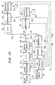
- FIG. 10 shows still an alternative embodiment of the electronic still camera according to the present invention.
- a memory 40, a magnetic recorder 50 and an optical recorder 30 are housed in the camera 10.
- this configuration is different from that of the camera 10 of FIG. 1 in that a magnetic recording unit 50 and an optical recording unit 30 are connected thereto without employing the connector 60.
- the other configurations are the same as those of the camera 10 of FIG. 1 and are hence will not described.
- an output from a frame memory 18 is fed to either one of the memory 40, the magnetic recording unit 50, the optical recording unit 30; in consequence, it is possible to select as the recording medium either one of the memory 40, the magnetic recording unit 50, and the optical recording unit 30.
- An appropriate recording operation can be accordingly conducted depending on conditions such as the shooting speed and the number of pictures to be shot.
- the semiconductor store means, the optical recording means, or the magnetic recording means can be selected as the recording medium, an appropriate recording operation can be therefore conducted depending on conditions such as the shooting speed and the volume of images to be shot.
Applications Claiming Priority (2)
| Application Number | Priority Date | Filing Date | Title |
|---|---|---|---|
| JP85120/88 | 1988-04-08 | ||
| JP8512088 | 1988-04-08 |
Publications (3)
| Publication Number | Publication Date |
|---|---|
| EP0336317A2 true EP0336317A2 (de) | 1989-10-11 |
| EP0336317A3 EP0336317A3 (de) | 1991-05-15 |
| EP0336317B1 EP0336317B1 (de) | 1995-07-19 |
Family
ID=13849769
Family Applications (1)
| Application Number | Title | Priority Date | Filing Date |
|---|---|---|---|
| EP89105711A Expired - Lifetime EP0336317B1 (de) | 1988-04-08 | 1989-03-31 | Elektronische Standbildkamera mit der Fähigkeit ein Aufzeichnungsmittel auszuwählen |
Country Status (3)
| Country | Link |
|---|---|
| US (1) | US5067029A (de) |
| EP (1) | EP0336317B1 (de) |
| DE (1) | DE68923472T2 (de) |
Cited By (20)
| Publication number | Priority date | Publication date | Assignee | Title |
|---|---|---|---|---|
| DE4029240A1 (de) * | 1989-09-14 | 1991-03-28 | Olympus Optical Co | Elektronisches still-kamerasystem mit aufnahme- und wiedergabefunktionen hoher qualitaet |
| EP0428310A2 (de) * | 1989-11-06 | 1991-05-22 | Canon Kabushiki Kaisha | Bildverarbeitungsvorrichtung und Bildübertragungsvorrichtung |
| GB2240446A (en) * | 1989-11-10 | 1991-07-31 | Konishiroku Photo Ind | Digital still video camera with selectable video signal processing speed |
| DE4108307A1 (de) * | 1990-03-16 | 1991-09-19 | Olympus Optical Co | Elektronische kamera |
| EP0448311A2 (de) * | 1990-03-16 | 1991-09-25 | Canon Kabushiki Kaisha | Bildkodierungs- und Aufzeichnungsgerät |
| FR2662322A1 (fr) * | 1990-05-15 | 1991-11-22 | Asahi Optical Co Ltd | Appareil photo electronique a image fixe et disque magnetique. |
| EP0469804A2 (de) * | 1990-07-30 | 1992-02-05 | Sony Corporation | Videosignalaufzeichnungs- und/oder Wiedergabegerät |
| EP0473516A2 (de) * | 1990-08-29 | 1992-03-04 | Sony Corporation | Digitale elektronische Standbildkamera |
| EP0474444A2 (de) * | 1990-09-04 | 1992-03-11 | Canon Kabushiki Kaisha | Bildverarbeitungsverfahren und -gerät |
| EP0485149A2 (de) * | 1990-11-07 | 1992-05-13 | Canon Kabushiki Kaisha | Aufzeichnungsgerät |
| EP0491556A2 (de) * | 1990-12-19 | 1992-06-24 | Canon Kabushiki Kaisha | Bildverarbeitungsverfahren und -gerät |
| US5216518A (en) * | 1990-09-04 | 1993-06-01 | Canon Kabushiki Kaisha | Image processing method and apparatus for encoding variable-length data |
| WO1994007240A1 (en) * | 1992-09-15 | 1994-03-31 | Samsung Electronics Co., Ltd. | Buffering method and system for resonant scanner |
| US5376965A (en) * | 1989-09-14 | 1994-12-27 | Olympus Optical Co., Ltd. | Electronic imaging system capable of recording/reproducing images with any one of several possible recording media |
| EP0752783A2 (de) * | 1991-11-21 | 1997-01-08 | Canon Kabushiki Kaisha | Informationssignalverarbeitungsvorrichtung |
| EP0777381A3 (de) * | 1995-12-07 | 1998-06-03 | Canon Kabushiki Kaisha | Bildaufnahmesystem mit Bildaufnahmeeinheit und Computer |
| EP0982926A2 (de) * | 1998-08-26 | 2000-03-01 | Matsushita Electric Industrial Co., Ltd. | Verfahren zur Speicherung von Standbildern auf einem Disk und Vorrichtung zur Speicherung und Wiedergabe von Standbilderna auf und aus einem Disk |
| US6085024A (en) * | 1990-04-25 | 2000-07-04 | Asahi Kogaku Kogyo Kabushiki Kaisha | Electronic still camera and magnetic disk |
| US6253023B1 (en) | 1991-11-21 | 2001-06-26 | Canon Kabushiki Kaisha | Image pickup device |
| WO2004025949A1 (en) | 2002-09-11 | 2004-03-25 | Casio Computer Co., Ltd. | Image-pickup apparatus, image recording apparatus, image-pickup control program, image recording program, image-pickup method and image recording method |
Families Citing this family (57)
| Publication number | Priority date | Publication date | Assignee | Title |
|---|---|---|---|---|
| JPH01278183A (ja) * | 1988-04-28 | 1989-11-08 | Canon Inc | デイジタル画像記録及び又は再生装置 |
| US20010033734A1 (en) * | 1989-05-02 | 2001-10-25 | Minolta Co., Ltd., | Image information processing system |
| EP0398295B1 (de) * | 1989-05-17 | 1996-08-14 | Minolta Co., Ltd. | Aufnahme- und Reprokamera |
| JP3100049B2 (ja) * | 1989-07-26 | 2000-10-16 | キヤノン株式会社 | 情報記録及び/又は再生装置、及び、その方法 |
| JPH0447876A (ja) * | 1990-06-15 | 1992-02-18 | Aiwa Co Ltd | ディジタル信号の記録再生方式 |
| US6549232B1 (en) * | 1990-07-18 | 2003-04-15 | Minolta Co., Ltd. | Still video camera in which erroneous erasure of picture image is prevented |
| JP3103151B2 (ja) * | 1990-09-03 | 2000-10-23 | 富士写真フイルム株式会社 | 電子スチル・カメラおよびその動作制御方法 |
| US5138459A (en) | 1990-11-20 | 1992-08-11 | Personal Computer Cameras, Inc. | Electronic still video camera with direct personal computer (pc) compatible digital format output |
| US5293236A (en) * | 1991-01-11 | 1994-03-08 | Fuji Photo Film Co., Ltd. | Electronic still camera including an EEPROM memory card and having a continuous shoot mode |
| US5576840A (en) * | 1991-07-18 | 1996-11-19 | Canon Kabushiki Kaisha | Recording apparatus |
| JPH05137041A (ja) * | 1991-08-30 | 1993-06-01 | Fuji Photo Film Co Ltd | デジタル電子スチルカメラ |
| US5576839A (en) * | 1991-09-25 | 1996-11-19 | Minolta Camera Kabushiki Kaisha | Camera system including a separatable recorder |
| US5857059A (en) * | 1991-10-31 | 1999-01-05 | Canon Kabushiki Kaisha | Information recording apparatus |
| CA2081742C (en) * | 1991-11-13 | 2000-05-23 | Anthony M. Radice | Apparatus and method for recording random data on a digital video recorder |
| US5806072A (en) * | 1991-12-20 | 1998-09-08 | Olympus Optical Co., Ltd. | Electronic imaging apparatus having hierarchical image data storage structure for computer-compatible image data management |
| GB2264838B (en) * | 1992-02-21 | 1995-08-30 | Samsung Electronics Co Ltd | Video recording apparatus |
| US5268963A (en) * | 1992-06-09 | 1993-12-07 | Audio Digital Imaging Inc. | System for encoding personalized identification for storage on memory storage devices |
| US5214699A (en) * | 1992-06-09 | 1993-05-25 | Audio Digital Imaging Inc. | System for decoding and displaying personalized indentification stored on memory storage device |
| US5259025A (en) * | 1992-06-12 | 1993-11-02 | Audio Digitalimaging, Inc. | Method of verifying fake-proof video identification data |
| DE69324972T2 (de) * | 1992-08-31 | 2000-02-17 | Canon Kk | Bildaufnahmegerät |
| US8046800B2 (en) * | 1993-03-29 | 2011-10-25 | Microsoft Corporation | Remotely controlling a video recorder |
| US20020048448A1 (en) * | 1993-03-29 | 2002-04-25 | Microsoft Corporation | Pausing the display of a television program as a signal including the television program is received |
| JP3372289B2 (ja) * | 1993-04-28 | 2003-01-27 | 富士写真フイルム株式会社 | ディジタルカメラ |
| JP3764493B2 (ja) * | 1993-09-20 | 2006-04-05 | ソニー株式会社 | 電子スチルカメラ及び画像データ処理方法 |
| JP3260216B2 (ja) * | 1993-09-24 | 2002-02-25 | 旭光学工業株式会社 | Ccdディジタルカメラシステム |
| JP3320859B2 (ja) * | 1993-09-24 | 2002-09-03 | 旭光学工業株式会社 | Ccdディジタルカメラ |
| JPH07182768A (ja) * | 1993-12-22 | 1995-07-21 | Canon Inc | 記録装置 |
| US5640203A (en) * | 1994-02-16 | 1997-06-17 | Asahi Kogaku Kogyo Kabushiki Kaisha | Recording operation control device |
| JP3203290B2 (ja) * | 1994-03-31 | 2001-08-27 | 富士写真フイルム株式会社 | ディジタル電子スチル・カメラおよびメモリ・カードへの記録方法 |
| GB2296600B (en) * | 1994-08-12 | 1999-04-07 | Sony Corp | Portable AV editing apparatus |
| JP3528335B2 (ja) * | 1994-08-22 | 2004-05-17 | 株式会社日立製作所 | ビデオカメラシステム |
| JPH0922581A (ja) * | 1995-07-03 | 1997-01-21 | Sony Corp | Vtr一体型カメラ装置 |
| JP3776493B2 (ja) | 1995-12-27 | 2006-05-17 | オリンパス株式会社 | 画像記録装置 |
| US5953481A (en) * | 1996-01-08 | 1999-09-14 | Canon Kabushiki Kaisha | Reproducing apparatus having an editing function |
| JP3630851B2 (ja) * | 1996-05-31 | 2005-03-23 | キヤノン株式会社 | 撮像記録装置 |
| WO1998057495A1 (en) * | 1997-06-12 | 1998-12-17 | Lewis William H | Multi-functional processing system with built-in non-movable storage medium |
| US5973734A (en) | 1997-07-09 | 1999-10-26 | Flashpoint Technology, Inc. | Method and apparatus for correcting aspect ratio in a camera graphical user interface |
| JP2000050194A (ja) * | 1998-07-27 | 2000-02-18 | Sony Corp | 撮像装置 |
| US6317141B1 (en) | 1998-12-31 | 2001-11-13 | Flashpoint Technology, Inc. | Method and apparatus for editing heterogeneous media objects in a digital imaging device |
| DE19902537C2 (de) * | 1999-01-22 | 2000-11-30 | Siemens Ag | Vorrichtung und Verfahren zur Erzeugung eines komprimierten Datenstroms |
| JP3931942B2 (ja) * | 1999-02-02 | 2007-06-20 | 富士フイルム株式会社 | 画像ファイル装置 |
| US7372485B1 (en) | 1999-06-08 | 2008-05-13 | Lightsurf Technologies, Inc. | Digital camera device and methodology for distributed processing and wireless transmission of digital images |
| US7369161B2 (en) * | 1999-06-08 | 2008-05-06 | Lightsurf Technologies, Inc. | Digital camera device providing improved methodology for rapidly taking successive pictures |
| US8212893B2 (en) | 1999-06-08 | 2012-07-03 | Verisign, Inc. | Digital camera device and methodology for distributed processing and wireless transmission of digital images |
| US7103357B2 (en) * | 1999-11-05 | 2006-09-05 | Lightsurf Technologies, Inc. | Media spooler system and methodology providing efficient transmission of media content from wireless devices |
| JP2001169224A (ja) * | 1999-12-09 | 2001-06-22 | Minolta Co Ltd | デジタルカメラ |
| JP2001177793A (ja) * | 1999-12-17 | 2001-06-29 | Minolta Co Ltd | デジタルカメラおよび画像記録システム |
| US7847833B2 (en) * | 2001-02-07 | 2010-12-07 | Verisign, Inc. | Digital camera device providing improved methodology for rapidly taking successive pictures |
| US7424207B2 (en) * | 2000-02-18 | 2008-09-09 | Sanyo Electric Co., Ltd. | Digital camera |
| US7305354B2 (en) | 2001-03-20 | 2007-12-04 | Lightsurf,Technologies, Inc. | Media asset management system |
| US7107608B2 (en) | 2001-10-01 | 2006-09-12 | Microsoft Corporation | Remote task scheduling for a set top box |
| US7724281B2 (en) | 2002-02-04 | 2010-05-25 | Syniverse Icx Corporation | Device facilitating efficient transfer of digital content from media capture device |
| US7051040B2 (en) | 2002-07-23 | 2006-05-23 | Lightsurf Technologies, Inc. | Imaging system providing dynamic viewport layering |
| JP3735864B2 (ja) * | 2002-10-28 | 2006-01-18 | ソニー株式会社 | 情報記録処理装置、情報再生処理装置、および方法、並びにコンピュータ・プログラム |
| KR20050112567A (ko) * | 2004-05-27 | 2005-12-01 | 삼성테크윈 주식회사 | 편리한 재생을 위한 디지털 촬영 장치의 제어 방법 |
| JP4546331B2 (ja) * | 2004-07-23 | 2010-09-15 | キヤノン株式会社 | ビデオカメラ |
| US9224145B1 (en) | 2006-08-30 | 2015-12-29 | Qurio Holdings, Inc. | Venue based digital rights using capture device with digital watermarking capability |
Citations (5)
| Publication number | Priority date | Publication date | Assignee | Title |
|---|---|---|---|---|
| US4130834A (en) * | 1974-12-20 | 1978-12-19 | Videoprint Gesellschaft Fur Industrie-Fernsehen Mbh | Method of and apparatus for the production of photographic stills |
| US4131919A (en) * | 1977-05-20 | 1978-12-26 | Eastman Kodak Company | Electronic still camera |
| EP0101600A2 (de) * | 1982-08-20 | 1984-02-29 | Olympus Optical Co., Ltd. | Videosignal-Aufzeichnungsgerät |
| JPS59183592A (ja) * | 1983-04-04 | 1984-10-18 | Nippon Hoso Kyokai <Nhk> | 色分離情報を記憶させた電子スチルカメラ |
| US4604668A (en) * | 1980-11-21 | 1986-08-05 | Lemelson Jerome H | Portable television camera and recording unit |
Family Cites Families (8)
| Publication number | Priority date | Publication date | Assignee | Title |
|---|---|---|---|---|
| US4189744A (en) * | 1976-12-20 | 1980-02-19 | New York Institute Of Technology | Apparatus for generating signals representing operator-selected portions of a scene |
| JPS5778286A (en) * | 1980-10-31 | 1982-05-15 | Nippon Kogaku Kk <Nikon> | Electronic camera |
| BE890517A (fr) * | 1981-09-28 | 1982-01-18 | Staar Sa | Dispositif de memorisation d'images electroniques |
| US4520401A (en) * | 1982-04-16 | 1985-05-28 | Victor Company Of Japan, Ltd. | Digital video signal recording system and reproducing apparatus |
| JPS58215884A (ja) * | 1982-06-10 | 1983-12-15 | Sony Corp | 電子カメラ |
| JPS5998336A (ja) * | 1982-11-29 | 1984-06-06 | Toshiba Corp | 情報信号の記録再生ヘツド |
| US4691253A (en) * | 1985-05-13 | 1987-09-01 | Polaroid Corporation | Electronic imaging camera for recording either moving or still images |
| JPH0761139B2 (ja) * | 1986-09-20 | 1995-06-28 | パイオニア株式会社 | 静止画記録再生装置 |
-
1989
- 1989-03-31 DE DE68923472T patent/DE68923472T2/de not_active Expired - Lifetime
- 1989-03-31 EP EP89105711A patent/EP0336317B1/de not_active Expired - Lifetime
- 1989-04-06 US US07/333,914 patent/US5067029A/en not_active Expired - Lifetime
Patent Citations (5)
| Publication number | Priority date | Publication date | Assignee | Title |
|---|---|---|---|---|
| US4130834A (en) * | 1974-12-20 | 1978-12-19 | Videoprint Gesellschaft Fur Industrie-Fernsehen Mbh | Method of and apparatus for the production of photographic stills |
| US4131919A (en) * | 1977-05-20 | 1978-12-26 | Eastman Kodak Company | Electronic still camera |
| US4604668A (en) * | 1980-11-21 | 1986-08-05 | Lemelson Jerome H | Portable television camera and recording unit |
| EP0101600A2 (de) * | 1982-08-20 | 1984-02-29 | Olympus Optical Co., Ltd. | Videosignal-Aufzeichnungsgerät |
| JPS59183592A (ja) * | 1983-04-04 | 1984-10-18 | Nippon Hoso Kyokai <Nhk> | 色分離情報を記憶させた電子スチルカメラ |
Non-Patent Citations (1)
| Title |
|---|
| PATENT ABSTRACTS OF JAPAN, vol. 9, no. 43 (E-298)[1766], 22nd February 1985; & JP-A-59 183 592 (NIPPON HOSO KYOKAI) 18-10-1984 * |
Cited By (49)
| Publication number | Priority date | Publication date | Assignee | Title |
|---|---|---|---|---|
| DE4029240C2 (de) * | 1989-09-14 | 2003-04-17 | Olympus Optical Co | Elektronisches Still-Kamerasystem mit Aufnahme- und Wiedergabefunktionen hoher Qualität |
| US5376965A (en) * | 1989-09-14 | 1994-12-27 | Olympus Optical Co., Ltd. | Electronic imaging system capable of recording/reproducing images with any one of several possible recording media |
| DE4029240A1 (de) * | 1989-09-14 | 1991-03-28 | Olympus Optical Co | Elektronisches still-kamerasystem mit aufnahme- und wiedergabefunktionen hoher qualitaet |
| EP0428310A2 (de) * | 1989-11-06 | 1991-05-22 | Canon Kabushiki Kaisha | Bildverarbeitungsvorrichtung und Bildübertragungsvorrichtung |
| EP0719036A2 (de) * | 1989-11-06 | 1996-06-26 | Canon Kabushiki Kaisha | Elektronische Standbildkamera |
| EP0719036A3 (de) * | 1989-11-06 | 1996-12-27 | Canon Kk | Elektronische Standbildkamera |
| EP0428310A3 (en) * | 1989-11-06 | 1992-08-05 | Canon Kabushiki Kaisha | Image processing apparatus and image transmitting apparatus |
| GB2240446A (en) * | 1989-11-10 | 1991-07-31 | Konishiroku Photo Ind | Digital still video camera with selectable video signal processing speed |
| EP0448311A2 (de) * | 1990-03-16 | 1991-09-25 | Canon Kabushiki Kaisha | Bildkodierungs- und Aufzeichnungsgerät |
| EP1353494A2 (de) * | 1990-03-16 | 2003-10-15 | Canon Kabushiki Kaisha | Bildkodierungs- und Aufzeichnungsgerät |
| EP0917350A3 (de) * | 1990-03-16 | 1999-06-02 | Canon Kabushiki Kaisha | Bildkodierungs- und -aufzeichnungsgerät |
| EP1353494A3 (de) * | 1990-03-16 | 2004-07-28 | Canon Kabushiki Kaisha | Bildkodierungs- und Aufzeichnungsgerät |
| EP0917350A2 (de) * | 1990-03-16 | 1999-05-19 | Canon Kabushiki Kaisha | Bildkodierungs- und -aufzeichnungsgerät |
| US5903677A (en) * | 1990-03-16 | 1999-05-11 | Canon Kabushiki Kaisha | Image encoding and recording apparatus |
| US7130074B2 (en) | 1990-03-16 | 2006-10-31 | Canon Kabushiki Kaisha | Image encoding and recording apparatus |
| EP0448311A3 (en) * | 1990-03-16 | 1993-04-07 | Canon Kabushiki Kaisha | Image encoding and recording apparatus |
| DE4108307A1 (de) * | 1990-03-16 | 1991-09-19 | Olympus Optical Co | Elektronische kamera |
| US6085024A (en) * | 1990-04-25 | 2000-07-04 | Asahi Kogaku Kogyo Kabushiki Kaisha | Electronic still camera and magnetic disk |
| FR2662322A1 (fr) * | 1990-05-15 | 1991-11-22 | Asahi Optical Co Ltd | Appareil photo electronique a image fixe et disque magnetique. |
| EP0469804A2 (de) * | 1990-07-30 | 1992-02-05 | Sony Corporation | Videosignalaufzeichnungs- und/oder Wiedergabegerät |
| US5412514A (en) * | 1990-07-30 | 1995-05-02 | Sony Corporation | Apparatus for recording and/or reproducing a video signal |
| EP0469804A3 (en) * | 1990-07-30 | 1993-06-30 | Sony Corporation | Apparatus for recording and/or reproducing a video signal |
| EP0473516A3 (en) * | 1990-08-29 | 1993-01-13 | Sony Corporation | Digital electronic still camera |
| US5274457A (en) * | 1990-08-29 | 1993-12-28 | Sony Corporation | Digital electronic still camera having removable record means |
| EP0473516A2 (de) * | 1990-08-29 | 1992-03-04 | Sony Corporation | Digitale elektronische Standbildkamera |
| EP0474444A2 (de) * | 1990-09-04 | 1992-03-11 | Canon Kabushiki Kaisha | Bildverarbeitungsverfahren und -gerät |
| EP0926883A1 (de) * | 1990-09-04 | 1999-06-30 | Canon Kabushiki Kaisha | Verfahren und Vorrichtung zur Bildverarbeitung |
| US5216518A (en) * | 1990-09-04 | 1993-06-01 | Canon Kabushiki Kaisha | Image processing method and apparatus for encoding variable-length data |
| US5745251A (en) * | 1990-09-04 | 1998-04-28 | Canon Kabushiki Kaisha | Image processing method and apparatus for encoding variable-length data |
| US5384644A (en) * | 1990-09-04 | 1995-01-24 | Canon Kabushiki Kaisha | Image processing method and apparatus for encoding variable-length data |
| EP0474444A3 (en) * | 1990-09-04 | 1992-10-07 | Canon Kabushiki Kaisha | Image processing method and apparatus |
| US7362961B2 (en) | 1990-11-07 | 2008-04-22 | Canon Kabushiki Kaisha | Recording apparatus including plural storage means having standby modes |
| EP0485149A3 (en) * | 1990-11-07 | 1993-04-28 | Canon Kabushiki Kaisha | Recording apparatus |
| EP0485149A2 (de) * | 1990-11-07 | 1992-05-13 | Canon Kabushiki Kaisha | Aufzeichnungsgerät |
| EP0491556A3 (en) * | 1990-12-19 | 1992-11-04 | Canon Kabushiki Kaisha | Image processing method and apparatus |
| EP0491556A2 (de) * | 1990-12-19 | 1992-06-24 | Canon Kabushiki Kaisha | Bildverarbeitungsverfahren und -gerät |
| US5588069A (en) * | 1990-12-19 | 1996-12-24 | Canon Kabushiki Kaisha | Image processing apparatus for advantageously encoding blocks of data having either substantially the same or varied colors |
| EP0752783A3 (de) * | 1991-11-21 | 1997-11-19 | Canon Kabushiki Kaisha | Informationssignalverarbeitungsvorrichtung |
| EP0752783A2 (de) * | 1991-11-21 | 1997-01-08 | Canon Kabushiki Kaisha | Informationssignalverarbeitungsvorrichtung |
| US6253023B1 (en) | 1991-11-21 | 2001-06-26 | Canon Kabushiki Kaisha | Image pickup device |
| WO1994007240A1 (en) * | 1992-09-15 | 1994-03-31 | Samsung Electronics Co., Ltd. | Buffering method and system for resonant scanner |
| US6870566B1 (en) | 1995-12-07 | 2005-03-22 | Canon Kabushiki Kaisha | Image sensing system for sensing an image and converting the image into image signals with a controlled operating rate |
| EP0777381A3 (de) * | 1995-12-07 | 1998-06-03 | Canon Kabushiki Kaisha | Bildaufnahmesystem mit Bildaufnahmeeinheit und Computer |
| US6636692B1 (en) | 1998-08-26 | 2003-10-21 | Matsushita Electric Industrial Co., Ltd. | Method for recording still pictures on disk and apparatus for recording and reproducing still pictures on and from disk |
| EP0982926A2 (de) * | 1998-08-26 | 2000-03-01 | Matsushita Electric Industrial Co., Ltd. | Verfahren zur Speicherung von Standbildern auf einem Disk und Vorrichtung zur Speicherung und Wiedergabe von Standbilderna auf und aus einem Disk |
| EP0982926A3 (de) * | 1998-08-26 | 2001-03-28 | Matsushita Electric Industrial Co., Ltd. | Verfahren zur Speicherung von Standbildern auf einem Disk und Vorrichtung zur Speicherung und Wiedergabe von Standbilderna auf und aus einem Disk |
| WO2004025949A1 (en) | 2002-09-11 | 2004-03-25 | Casio Computer Co., Ltd. | Image-pickup apparatus, image recording apparatus, image-pickup control program, image recording program, image-pickup method and image recording method |
| KR100774053B1 (ko) * | 2002-09-11 | 2007-11-06 | 가시오게산키 가부시키가이샤 | 영상 픽업장치, 영상 기록장치, 영상 픽업장치를 위한 프로그램을 기록한 컴퓨터 판독 가능 기록 매체, 영상 기록장치를 위한 프로그램을 기록한 컴퓨터 판독 가능 기록 매체, 영상 픽업방법 및 영상 기록방법 |
| US7486314B2 (en) | 2002-09-11 | 2009-02-03 | Casio Computer Co., Ltd. | Image-pickup apparatus, image recording apparatus, image-pickup control program, image recording program, image-pickup method and image recording method |
Also Published As
| Publication number | Publication date |
|---|---|
| EP0336317B1 (de) | 1995-07-19 |
| EP0336317A3 (de) | 1991-05-15 |
| US5067029A (en) | 1991-11-19 |
| DE68923472T2 (de) | 1995-12-07 |
| DE68923472D1 (de) | 1995-08-24 |
Similar Documents
| Publication | Publication Date | Title |
|---|---|---|
| US5067029A (en) | Electronic still camera capable of selecting recording media | |
| US4642700A (en) | Method of and apparatus for producing video signal associated with photographic image | |
| US4641198A (en) | Method of and apparatus for recording video signal associated with photographic image | |
| US4660102A (en) | Electronic still camera capable of editing picture recorded on disk | |
| US6928229B2 (en) | Recording and reproducing apparatus storing data of a number of sub-frames | |
| US5740303A (en) | Magnetic recording system and method for a digital still video recorder | |
| KR100210488B1 (ko) | 연속 촬영 및 선택 저장 지능을 지닌 디지탈 스틸 카메라 | |
| JPH0338986A (ja) | スチルビデオカメラ | |
| JP2543171B2 (ja) | 電子スチルカメラ | |
| JPS59131274A (ja) | 像撮影装置 | |
| KR100215304B1 (ko) | 정지화상 기록기능을 가지는 비디오 카메라 | |
| JPH08275110A (ja) | ディジタル画像データ記録装置および方法ならびにディジタル画像データ再生装置および方法 | |
| JPH0514776A (ja) | カメラ情報蓄積装置 | |
| JPH02278973A (ja) | 映像信号記録・再生装置 | |
| JPH04119756A (ja) | 静止画像記録装置 | |
| JP2926794B2 (ja) | 画像送信装置 | |
| JPH02207691A (ja) | 画像データ記録装置 | |
| JP2783590B2 (ja) | 画像記録再生装置 | |
| JP2771149B2 (ja) | 画像処理装置 | |
| JPH10224673A (ja) | 電子スチルカメラ | |
| JPH04348675A (ja) | 高精細度静止画像取り込み装置 | |
| JPH02222384A (ja) | 画像記録再生システム | |
| JPS6130874A (ja) | 画像記録装置 | |
| JPH0340690A (ja) | スチルビデオカメラとその再生装置 | |
| JPH0271680A (ja) | 撮像装置 |
Legal Events
| Date | Code | Title | Description |
|---|---|---|---|
| PUAI | Public reference made under article 153(3) epc to a published international application that has entered the european phase |
Free format text: ORIGINAL CODE: 0009012 |
|
| AK | Designated contracting states |
Kind code of ref document: A2 Designated state(s): DE GB NL |
|
| PUAL | Search report despatched |
Free format text: ORIGINAL CODE: 0009013 |
|
| AK | Designated contracting states |
Kind code of ref document: A3 Designated state(s): DE GB NL |
|
| 17P | Request for examination filed |
Effective date: 19911030 |
|
| 17Q | First examination report despatched |
Effective date: 19931027 |
|
| GRAA | (expected) grant |
Free format text: ORIGINAL CODE: 0009210 |
|
| AK | Designated contracting states |
Kind code of ref document: B1 Designated state(s): DE GB NL |
|
| REF | Corresponds to: |
Ref document number: 68923472 Country of ref document: DE Date of ref document: 19950824 |
|
| PLBE | No opposition filed within time limit |
Free format text: ORIGINAL CODE: 0009261 |
|
| STAA | Information on the status of an ep patent application or granted ep patent |
Free format text: STATUS: NO OPPOSITION FILED WITHIN TIME LIMIT |
|
| 26N | No opposition filed | ||
| REG | Reference to a national code |
Ref country code: GB Ref legal event code: IF02 |
|
| REG | Reference to a national code |
Ref country code: GB Ref legal event code: 732E |
|
| PGFP | Annual fee paid to national office [announced via postgrant information from national office to epo] |
Ref country code: GB Payment date: 20080326 Year of fee payment: 20 Ref country code: NL Payment date: 20080326 Year of fee payment: 20 |
|
| PGFP | Annual fee paid to national office [announced via postgrant information from national office to epo] |
Ref country code: DE Payment date: 20080429 Year of fee payment: 20 |
|
| REG | Reference to a national code |
Ref country code: GB Ref legal event code: PE20 Expiry date: 20090330 |
|
| PG25 | Lapsed in a contracting state [announced via postgrant information from national office to epo] |
Ref country code: NL Free format text: LAPSE BECAUSE OF EXPIRATION OF PROTECTION Effective date: 20090331 |
|
| NLV7 | Nl: ceased due to reaching the maximum lifetime of a patent |
Effective date: 20090331 |
|
| PG25 | Lapsed in a contracting state [announced via postgrant information from national office to epo] |
Ref country code: GB Free format text: LAPSE BECAUSE OF EXPIRATION OF PROTECTION Effective date: 20090330 |