EP0917350A2 - Bildkodierungs- und -aufzeichnungsgerät - Google Patents
Bildkodierungs- und -aufzeichnungsgerät Download PDFInfo
- Publication number
- EP0917350A2 EP0917350A2 EP99200168A EP99200168A EP0917350A2 EP 0917350 A2 EP0917350 A2 EP 0917350A2 EP 99200168 A EP99200168 A EP 99200168A EP 99200168 A EP99200168 A EP 99200168A EP 0917350 A2 EP0917350 A2 EP 0917350A2
- Authority
- EP
- European Patent Office
- Prior art keywords
- recording
- data
- image
- image data
- generating
- Prior art date
- Legal status (The legal status is an assumption and is not a legal conclusion. Google has not performed a legal analysis and makes no representation as to the accuracy of the status listed.)
- Granted
Links
Images


Classifications
-
- H—ELECTRICITY
- H04—ELECTRIC COMMUNICATION TECHNIQUE
- H04N—PICTORIAL COMMUNICATION, e.g. TELEVISION
- H04N19/00—Methods or arrangements for coding, decoding, compressing or decompressing digital video signals
-
- H—ELECTRICITY
- H04—ELECTRIC COMMUNICATION TECHNIQUE
- H04N—PICTORIAL COMMUNICATION, e.g. TELEVISION
- H04N1/00—Scanning, transmission or reproduction of documents or the like, e.g. facsimile transmission; Details thereof
- H04N1/21—Intermediate information storage
- H04N1/2104—Intermediate information storage for one or a few pictures
- H04N1/2112—Intermediate information storage for one or a few pictures using still video cameras
- H04N1/2129—Recording in, or reproducing from, a specific memory area or areas, or recording or reproducing at a specific moment
-
- H—ELECTRICITY
- H04—ELECTRIC COMMUNICATION TECHNIQUE
- H04N—PICTORIAL COMMUNICATION, e.g. TELEVISION
- H04N1/00—Scanning, transmission or reproduction of documents or the like, e.g. facsimile transmission; Details thereof
- H04N1/21—Intermediate information storage
- H04N1/2104—Intermediate information storage for one or a few pictures
- H04N1/2112—Intermediate information storage for one or a few pictures using still video cameras
- H04N1/2137—Intermediate information storage for one or a few pictures using still video cameras with temporary storage before final recording, e.g. in a frame buffer
-
- H—ELECTRICITY
- H04—ELECTRIC COMMUNICATION TECHNIQUE
- H04N—PICTORIAL COMMUNICATION, e.g. TELEVISION
- H04N1/00—Scanning, transmission or reproduction of documents or the like, e.g. facsimile transmission; Details thereof
- H04N1/21—Intermediate information storage
- H04N1/2104—Intermediate information storage for one or a few pictures
- H04N1/2112—Intermediate information storage for one or a few pictures using still video cameras
- H04N1/215—Recording a sequence of still pictures, e.g. burst mode
-
- H—ELECTRICITY
- H04—ELECTRIC COMMUNICATION TECHNIQUE
- H04N—PICTORIAL COMMUNICATION, e.g. TELEVISION
- H04N1/00—Scanning, transmission or reproduction of documents or the like, e.g. facsimile transmission; Details thereof
- H04N1/21—Intermediate information storage
- H04N1/2104—Intermediate information storage for one or a few pictures
- H04N1/2158—Intermediate information storage for one or a few pictures using a detachable storage unit
-
- H—ELECTRICITY
- H04—ELECTRIC COMMUNICATION TECHNIQUE
- H04N—PICTORIAL COMMUNICATION, e.g. TELEVISION
- H04N1/00—Scanning, transmission or reproduction of documents or the like, e.g. facsimile transmission; Details thereof
- H04N1/41—Bandwidth or redundancy reduction
-
- H—ELECTRICITY
- H04—ELECTRIC COMMUNICATION TECHNIQUE
- H04N—PICTORIAL COMMUNICATION, e.g. TELEVISION
- H04N19/00—Methods or arrangements for coding, decoding, compressing or decompressing digital video signals
- H04N19/10—Methods or arrangements for coding, decoding, compressing or decompressing digital video signals using adaptive coding
- H04N19/134—Methods or arrangements for coding, decoding, compressing or decompressing digital video signals using adaptive coding characterised by the element, parameter or criterion affecting or controlling the adaptive coding
- H04N19/146—Data rate or code amount at the encoder output
- H04N19/152—Data rate or code amount at the encoder output by measuring the fullness of the transmission buffer
-
- H—ELECTRICITY
- H04—ELECTRIC COMMUNICATION TECHNIQUE
- H04N—PICTORIAL COMMUNICATION, e.g. TELEVISION
- H04N19/00—Methods or arrangements for coding, decoding, compressing or decompressing digital video signals
- H04N19/10—Methods or arrangements for coding, decoding, compressing or decompressing digital video signals using adaptive coding
- H04N19/134—Methods or arrangements for coding, decoding, compressing or decompressing digital video signals using adaptive coding characterised by the element, parameter or criterion affecting or controlling the adaptive coding
- H04N19/162—User input
-
- H—ELECTRICITY
- H04—ELECTRIC COMMUNICATION TECHNIQUE
- H04N—PICTORIAL COMMUNICATION, e.g. TELEVISION
- H04N19/00—Methods or arrangements for coding, decoding, compressing or decompressing digital video signals
- H04N19/10—Methods or arrangements for coding, decoding, compressing or decompressing digital video signals using adaptive coding
- H04N19/169—Methods or arrangements for coding, decoding, compressing or decompressing digital video signals using adaptive coding characterised by the coding unit, i.e. the structural portion or semantic portion of the video signal being the object or the subject of the adaptive coding
- H04N19/17—Methods or arrangements for coding, decoding, compressing or decompressing digital video signals using adaptive coding characterised by the coding unit, i.e. the structural portion or semantic portion of the video signal being the object or the subject of the adaptive coding the unit being an image region, e.g. an object
- H04N19/172—Methods or arrangements for coding, decoding, compressing or decompressing digital video signals using adaptive coding characterised by the coding unit, i.e. the structural portion or semantic portion of the video signal being the object or the subject of the adaptive coding the unit being an image region, e.g. an object the region being a picture, frame or field
-
- H—ELECTRICITY
- H04—ELECTRIC COMMUNICATION TECHNIQUE
- H04N—PICTORIAL COMMUNICATION, e.g. TELEVISION
- H04N19/00—Methods or arrangements for coding, decoding, compressing or decompressing digital video signals
- H04N19/10—Methods or arrangements for coding, decoding, compressing or decompressing digital video signals using adaptive coding
- H04N19/169—Methods or arrangements for coding, decoding, compressing or decompressing digital video signals using adaptive coding characterised by the coding unit, i.e. the structural portion or semantic portion of the video signal being the object or the subject of the adaptive coding
- H04N19/184—Methods or arrangements for coding, decoding, compressing or decompressing digital video signals using adaptive coding characterised by the coding unit, i.e. the structural portion or semantic portion of the video signal being the object or the subject of the adaptive coding the unit being bits, e.g. of the compressed video stream
-
- H—ELECTRICITY
- H04—ELECTRIC COMMUNICATION TECHNIQUE
- H04N—PICTORIAL COMMUNICATION, e.g. TELEVISION
- H04N19/00—Methods or arrangements for coding, decoding, compressing or decompressing digital video signals
- H04N19/10—Methods or arrangements for coding, decoding, compressing or decompressing digital video signals using adaptive coding
- H04N19/189—Methods or arrangements for coding, decoding, compressing or decompressing digital video signals using adaptive coding characterised by the adaptation method, adaptation tool or adaptation type used for the adaptive coding
- H04N19/192—Methods or arrangements for coding, decoding, compressing or decompressing digital video signals using adaptive coding characterised by the adaptation method, adaptation tool or adaptation type used for the adaptive coding the adaptation method, adaptation tool or adaptation type being iterative or recursive
-
- H—ELECTRICITY
- H04—ELECTRIC COMMUNICATION TECHNIQUE
- H04N—PICTORIAL COMMUNICATION, e.g. TELEVISION
- H04N19/00—Methods or arrangements for coding, decoding, compressing or decompressing digital video signals
- H04N19/60—Methods or arrangements for coding, decoding, compressing or decompressing digital video signals using transform coding
-
- H—ELECTRICITY
- H04—ELECTRIC COMMUNICATION TECHNIQUE
- H04N—PICTORIAL COMMUNICATION, e.g. TELEVISION
- H04N5/00—Details of television systems
- H04N5/76—Television signal recording
- H04N5/765—Interface circuits between an apparatus for recording and another apparatus
- H04N5/77—Interface circuits between an apparatus for recording and another apparatus between a recording apparatus and a television camera
- H04N5/772—Interface circuits between an apparatus for recording and another apparatus between a recording apparatus and a television camera the recording apparatus and the television camera being placed in the same enclosure
-
- H—ELECTRICITY
- H04—ELECTRIC COMMUNICATION TECHNIQUE
- H04N—PICTORIAL COMMUNICATION, e.g. TELEVISION
- H04N19/00—Methods or arrangements for coding, decoding, compressing or decompressing digital video signals
- H04N19/10—Methods or arrangements for coding, decoding, compressing or decompressing digital video signals using adaptive coding
- H04N19/102—Methods or arrangements for coding, decoding, compressing or decompressing digital video signals using adaptive coding characterised by the element, parameter or selection affected or controlled by the adaptive coding
- H04N19/13—Adaptive entropy coding, e.g. adaptive variable length coding [AVLC] or context adaptive binary arithmetic coding [CABAC]
-
- H—ELECTRICITY
- H04—ELECTRIC COMMUNICATION TECHNIQUE
- H04N—PICTORIAL COMMUNICATION, e.g. TELEVISION
- H04N19/00—Methods or arrangements for coding, decoding, compressing or decompressing digital video signals
- H04N19/90—Methods or arrangements for coding, decoding, compressing or decompressing digital video signals using coding techniques not provided for in groups H04N19/10-H04N19/85, e.g. fractals
- H04N19/91—Entropy coding, e.g. variable length coding [VLC] or arithmetic coding
-
- H—ELECTRICITY
- H04—ELECTRIC COMMUNICATION TECHNIQUE
- H04N—PICTORIAL COMMUNICATION, e.g. TELEVISION
- H04N2101/00—Still video cameras
-
- H—ELECTRICITY
- H04—ELECTRIC COMMUNICATION TECHNIQUE
- H04N—PICTORIAL COMMUNICATION, e.g. TELEVISION
- H04N2201/00—Indexing scheme relating to scanning, transmission or reproduction of documents or the like, and to details thereof
- H04N2201/21—Intermediate information storage
- H04N2201/214—Checking or indicating the storage space
-
- H—ELECTRICITY
- H04—ELECTRIC COMMUNICATION TECHNIQUE
- H04N—PICTORIAL COMMUNICATION, e.g. TELEVISION
- H04N5/00—Details of television systems
- H04N5/76—Television signal recording
- H04N5/78—Television signal recording using magnetic recording
- H04N5/781—Television signal recording using magnetic recording on disks or drums
-
- H—ELECTRICITY
- H04—ELECTRIC COMMUNICATION TECHNIQUE
- H04N—PICTORIAL COMMUNICATION, e.g. TELEVISION
- H04N5/00—Details of television systems
- H04N5/76—Television signal recording
- H04N5/84—Television signal recording using optical recording
- H04N5/85—Television signal recording using optical recording on discs or drums
-
- H—ELECTRICITY
- H04—ELECTRIC COMMUNICATION TECHNIQUE
- H04N—PICTORIAL COMMUNICATION, e.g. TELEVISION
- H04N5/00—Details of television systems
- H04N5/76—Television signal recording
- H04N5/907—Television signal recording using static stores, e.g. storage tubes or semiconductor memories
-
- H—ELECTRICITY
- H04—ELECTRIC COMMUNICATION TECHNIQUE
- H04N—PICTORIAL COMMUNICATION, e.g. TELEVISION
- H04N5/00—Details of television systems
- H04N5/76—Television signal recording
- H04N5/91—Television signal processing therefor
- H04N5/92—Transformation of the television signal for recording, e.g. modulation, frequency changing; Inverse transformation for playback
- H04N5/926—Transformation of the television signal for recording, e.g. modulation, frequency changing; Inverse transformation for playback by pulse code modulation
- H04N5/9261—Transformation of the television signal for recording, e.g. modulation, frequency changing; Inverse transformation for playback by pulse code modulation involving data reduction
- H04N5/9264—Transformation of the television signal for recording, e.g. modulation, frequency changing; Inverse transformation for playback by pulse code modulation involving data reduction using transform coding
-
- H—ELECTRICITY
- H04—ELECTRIC COMMUNICATION TECHNIQUE
- H04N—PICTORIAL COMMUNICATION, e.g. TELEVISION
- H04N9/00—Details of colour television systems
- H04N9/79—Processing of colour television signals in connection with recording
- H04N9/80—Transformation of the television signal for recording, e.g. modulation, frequency changing; Inverse transformation for playback
- H04N9/804—Transformation of the television signal for recording, e.g. modulation, frequency changing; Inverse transformation for playback involving pulse code modulation of the colour picture signal components
- H04N9/8042—Transformation of the television signal for recording, e.g. modulation, frequency changing; Inverse transformation for playback involving pulse code modulation of the colour picture signal components involving data reduction
- H04N9/8047—Transformation of the television signal for recording, e.g. modulation, frequency changing; Inverse transformation for playback involving pulse code modulation of the colour picture signal components involving data reduction using transform coding
Definitions
- the present invention relates to an image encoding apparatus for compression encoding of image signal and an image recording apparatus for recording image signal.
- Conventional image recording apparatus for example still video camera, is based for example on analog signal recording on floppy disks or recording of digital image data, compressed by fixed length encoding, in semiconductor memory cards.
- the fixed length encoding means a compression encoding in such a manner that the amount of compressed codes of an image frame becomes equal to a predetermined value.
- Such conventional image signal recording methods can guarantee the number of images recordable per recording medium, because the capacity thereof required for recording image data of an image frame is predetermined.
- the rate of compression can empirically be only increased to the order of 8 bit/pixel, including the luminance and the color information, in order to guarantee the quality of compressed image for various image data, for example those involving fine patterns.
- the fixed length encoding cannot achieve a sufficiently high compression rate.
- a variable length encoding method can achieve efficient compression while guaranteeing sufficient image quality.
- the variable length encoding generates codes of variable length depending on the image, and empirically provides an encoding rate of 2 - 4 bit/pixel, including the luminance and color information and guaranteeing the image quality. In this case, however, it is not possible to guarantee the total number of images recordable per recording medium, because the total amount of codes varies according to the image. Also if the capacity of the recording medium is limited, the image may not be recordable on the recording medium.
- variable length encoding method if employed in a recording apparatus, results in a significant inconvenience as the user is unable to recognize, in advance, the number of images still recordable on the recording medium.
- an object of the present invention is to provide an image encoding method or apparatus, or an image recording method or apparatus, capable of individually or collectively resolving the drawbacks mentioned above.
- Another object of the present invention is to provide an image recording apparatus capable of presetting the stable recording conditions prior to the actual recording operation.
- Still another object of the present invention is to provide an apparatus allowing the operator to know, prior to a recording operation, whether such recording operation is possible or not.
- Still another object of the present invention is to provide an image recording apparatus employing a variable length encoding method and still convenient for use.
- an apparatus provided with first means for effecting variable length encoding on signals obtained by photoelectric conversion of an object image thereby generating variable length code data; recording means for recording said variable length code data on a medium; and second means for converting said object image to generate a value corresponding to the amount of said variable length code data, prior to the recording by said recording means.
- Still another object of the present invention is to provide an image encoding method or apparatus which is convenient for use and still allows efficient use of the recording capacity of the recording medium.
- Still another object of the present invention is to provide a novel image recording apparatus having image taking capability.
- Fig. 1 is a block diagram of an embodiment of the present invention.
- Other parts of the camera not directly related to the present invention such as the diaphragm and the shutter, are naturally provided but not shown.
- An optical image of an object, formed by a lens 1 is converted into an electrical image signal by an image pickup device 2, such as a charge-coupled device (CCD), positioned behind said lens.
- Said device 2 effects accumulation of charges corresponding to the optical image of the object and readout of image signal, in response to control signals given by a control unit 7.
- the obtained image signal is converted into a digital signal by an A/D converter 3.
- means for regulating the image signal such as gamma correction, formation and separation of color signals, white balance process etc. though such means are not illustrated.
- the digital image signal is stored in an image memory 4.
- a compression encoding circuit 5 effects compression encoding on the image data read from the image memory 4 and sends the obtained codes to a recording unit 6.
- the control unit 7 is so constructed as to control the recording and reproducing for example with MS-DOS commands through the recording unit 6.
- the compression is conducted by a variable length encoding or a fixed length encoding, for example by DCT conversion of the image as will be explained later, followed by entropy encoding.
- the recording unit 6 is provided with a recording medium such as a semiconductor memory or a tape-shaped medium, is capable of information exchange with the control unit, of recording or reading of arbitrary digital data at an arbitrary physical address of the recording medium, and of counting the empty capacity of said recording medium.
- a recording medium such as a semiconductor memory or a tape-shaped medium
- the control unit 7 controls the entire apparatus by controlling the units 2 - 6, and is also capable of controlling the image data files in the recording medium, through the recording unit.
- control unit 7 correlates the file information with the physical addresses on the recording medium, as in a disk operating system employed in a computer system, and is therefore capable of controlling the mode of recording of files (compressed image data) on the recording medium, and also the empty capacity thereof. If the compressed codes have to be stored in divided plural parts with a limited recording unit each, the control unit 7 causes the recording unit 6 to record the compressed codes by designating the physical address on the medium and the data length for each recording unit. When an image file is recorded in plural positions on the recording medium, the control unit 7 also records information indicating said positions, on the recording medium.
- a man-machine interface (MMIF) 8 includes an operation member 9 for actuating switches SW1, SW2 for shutter releasing and other switches to be explained later, and display devices 10 including a display in the view finder, an external LCD display, a buzzer etc.
- the images are fetched in the memory, encoded and stored in succession.
- the number of recordable images is calculated from the amount of codes of the image recorded immediately before and the empty capacity of the recording medium, and the decreased number of recordable images is displayed, in the present embodiment, in succession in the view finder.
- display need not necessarily be made in the view finder.
- the sequence shown in Fig. 4 is conducted after the step S23 in Fig. 3, namely storage of the image data in the memory 4.
- the image signal stored in the memory 4 is read and compression encoded in the encoding circuit 5, and thus compression encoded data are counted by the counting circuit 16 (S41). Then the amount of the compressed codes is compared with the empty capacity of the recording medium in the recording unit 6 (S43), and, if there is an enough empty capacity, a gate 18 is so controlled as to read the image signal again from the memory 4, to effect the compression encoding and to send the data to the recording unit 6 for recording.
- control unit 7 instructs the image memory to effect the readout of the image data, the compression encoding circuit 5 to release the compressed codes, the recording unit 6 to record the compressed codes, and the gate 18 to open the gate. It also designates the physical address and the data length on the medium for each recording unit to the recording unit 6 thereby recording the compressed codes. Unless a recording command is given by the control unit 7, the recording unit 6 does not request the data output from the compression encoding circuit 5, so that the function of said circuit 5 and the image memory 4 is interrupted. Thus the control unit 7 can achieve the recording operation through the control of the functions of the compression encoding circuit 5 and the image memory 4, by designating the physical address and the data length on the recording medium for each recording unit according to the filing format, to the recording unit.
- the recording operation is completed when all the compressed codes are recorded.
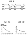
- Fig. 2 shows the communication protocol between the control unit 7 and the recording unit 6.
- Fig. 2 there are shown a data output request signal D-Req from the recording unit 6 to the control unit 7, a signal D-Ack supplied from the control unit 7 to the recording unit 6 and indicating that the data from the compression encoding circuit 5 to the recording unit 6 are effective; and 8-bit parallel output data D0 - D7 supplied from the compression encoding circuit 5 to the recording unit 6.
- Fig. 2 shows the output of data of one byte each, through the exchange of signals D-Req and D-Ack between the control unit 7 and the recording unit 6.
- the data receiver (namely recording unit 6) shifts the signal D-Req from the high level state to the low level state, thereby requesting the data transmitter (namely encoding circuit 5) to release the data. Detecting the low level state of said signal D-Req, the data transmitter release the data on the data bus (D0 - D7), and shifts the signal D-Ack from the high to the low level state when the values of said data are fixed.
- the data receiver fetches the signals on the data bus when the signal D-Ack is shifted to the low level state, and returns the signal D-Req to the high level state.
- the data transmitter terminates the data output to the data bus when the signal D-Req is shifted to the high level state, and returns the signal D-Ack to the high level state.
- the data transfer is thus conducted by matching the function of the transmitter and the receiver through the above-explained hand-shake communications of the signals Req and Ack. Consequently the compression encoding circuit 5 need not generate the compressed codes with a fixed transfer rate, and the eventual variation in the code length depending on the image does not cause any inconvenience.
- control unit causes the display unit 10 of the man-machine interface 8 to display that the recording operation is not possible because of an insufficient empty capacity of the recording medium, thereby requesting the user to select either one of the following three options:
- control unit 7 executes the steps S49, S51 and S53.
- control unit 7 displays the number of recorded images on the display unit 10 (S55), and requests the user to enter the sequential number of the image to be erased. In response to the entry by the user of the number of the image to be erased with the operation switches (S57), the control unit 7 erases the corresponding image file (S59) and the sequence returns to the step S43.
- the replacement of the recording medium may be mechanically detected by the recording unit as disclosed in the Japanese Laid-open Patent Sho 61-182669.
- the control unit 7 can make access to the information on the presence of such replacement through the recording unit 6.
- the above-explained control shown in Fig. 4 can ensure image recording to the user, even with a compression method with codes of variable length, thereby proving a system of improved convenience of use and still capable of guaranteeing the image quality.
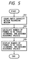
- Fig. 5 for explaining the method of displaying the number of recordable images, executed in the steps S11, S13 in Fig. 3.
- the control unit 7 releases a command for detecting the empty capacity, thereby causing the recording unit 6 to count the empty capacity of the recording medium (S61), and calculates the number of images recordable on the recording medium, from said empty capacity and the pre-stored representative value of the compression rate of the variable length encoding method (S63).
- a variable length encoding method disclosed in the Japanese Laid-open Patent Sho 63-124680 provides a code length of 2 bit/pixel in average or 4.5 bit/pixel at longest.
- a step S65 displays, on the display unit 10, a standard number of recordable images calculated from the average code length of 2 bit/pixel, and a minimum guaranteed number of recordable images calculated from 4.5 bit/pixel.
- the display device 10 is composed for example of a liquid crystal display (LCD) or light-emitting diodes (LED), and can provide display in the upper part of the apparatus and/or in the view finder.
- the above-explained embodiment provides a digital image recording apparatus employing variable length encoding, provided with means for counting the empty capacity of the recording medium and capable of storing the representative amount of compressed codes in variable length encoding, thereby calculating the number of images recordable on the recording medium from said calculated empty capacity and said representative amount, and further provided with means for displaying the calculated number of recordable images, thereby displaying a standard number and/or a minimum guaranteed number of images recordable on said recording medium.
- the empty capacity of the recording medium is detected not only in the step S1 in Fig. 3 but also in the steps S11, S13 of which details are shown in Fig. 5.
- said empty capacity can be confirmed not only when the switch SW1 is closed but also in a continuous recording operation.
- the present embodiment can improve the convenience of use and still can guarantee the image quality even with a variable length encoding method, since the amount of recorded images or the number of images recordable on the recording medium can be guaranteed and informed to the user.
- the amount of encoded data is calculated, prior to the recording operation by the recording unit 6, by actual variable length encoding of the image signal which is obtained by photoelectric conversion of the object image and stored in the memory 4, but the present invention is not limited to such embodiment and said amount of encoded data may be obtained without actual variable length encoding. Therefore the prediction of data amount from a simplified encoding is also included in the present invention.
- the data to be stored in the recording medium are in advance stored in the memory 4, and a signal indicating the amount of encoded data obtained by variable length encoding of the data stored in said memory 4 is generated by actual variable length encoding of the image signal obtained by photoelectric conversion of the object image and stored in said memory 4.
- the present invention is not limited to such embodiment, and the amount of encoded data may be obtained without the actual variable length encoding. Therefore, a prediction of the data amount for example by a simplified encoding is also included in the present invention.
- control unit 7 for executing the sequence shown in Fig. 4 controls said memory 4 according to the comparison of thus generated signal and said data amount.
- the present embodiment controls means for storing in advance the information to be stored in the recording medium, according to the comparison of the empty capacity of said recording medium and the amount of encoded data to be recorded, and can therefore continue the storage of said information in said storage means, if necessary.
- the present embodiment allows to know in advance the number of recordable images.
- the present embodiment generates a value corresponding to the amount of variable length data by conversion of the object image prior to the recording operation by the recording unit, so that certain measures can be taken in advance if the recording operation is impossible due to an excessively large amount of encoded data.
- ADCT adaptive compression transformation
- DCT dispersed cosine transformation
- the compression encoding circuit 5 can select variable length encoding or fixed length encoding, according to the aforementioned encoding method. More specifically, the variable length encoding is conducted with the encoding parameter F is fixed, and the fixed length encoding is conducted when the parameter F is varied to obtain a target code amount.
- control unit 7 can know such selection through the man-machine interface 8.
- control unit 7 controls the image pickup device 2, the A/D converter 3 and the image memory 4, thereby storing the digital data of the object image in said image memory 4.
- control unit 7 sets the parameter F of the compression encoding circuit 5, and causes said circuit 5 to compress the image data in the image memory and to count the compressed codes.
- said circuit 5 does not send the compressed codes to the recording unit but merely counts the amount of encoded data. This operation is repeated several times with different values of the parameter F, until a desired amount of encoded data is obtained.
- the control unit 7 When a value of F providing a desired amount of encoded data is obtained, the control unit 7 provides the compression encoding circuit 5 with said value, and instructs the recording unit 6 to release the compressed codes, thereby restarting the compressing operation. Then the control unit 7 instructs the recording unit 6 to record the compressed codes.
- the compressed codes with a fixed length for an image frame, are recorded by the recording unit.
- the control unit selects a sufficiently small value for the parameter F to be set in the encoding circuit 5, in order to avoid deterioration of the image quality.
- the value of F is fixed, and the initial operation of determining the value F in the recorded image number preferential mode is not conducted in this case.
- the control unit causes the compression encoding circuit to compress the image data in the image memory for supply to the recording unit 6, and causes said recording unit 6 to record thus obtained compressed codes.
- the number of recordable images and the continuous recording speed are also varied accordingly. More specifically, in the fixed length encoding, the number of recordable images can be exactly calculated by dividing the empty capacity of the recording medium with the amount of codes, since the latter is fixed. However, said number cannot be exactly determined in the variable length encoding. Also the variable length encoding, involving repeated process of plural times, required a longer time before recording than in the fixed length encoding, so that the selectable continuous recording speed becomes lower.
- control unit 7 in the variable length encoding mode determines the number of recordable images by dividing the empty capacity of the recording medium with the standard or maximum code amount and displays said number. In the fixed length encoding mode, it decreases the upper limit of the selectable continuous recording speed.
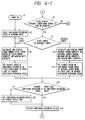
- Fig. 6 is a flow chart for the above-explained procedures. At first, when the power supply is turned on (S1), for example the fixed length encoding mode is selected, and the minimum continuous recording speed is selected (S3).
- the change of the fixed/variable length encoding mode is conducted by the user at a terminal S. Also if an instruction is given for varying the continuous recording speed, a corresponding procedure is conducted.
- the sequence proceeds to a step S5.
- the empty capacity of the recording medium is divided with the code amount, and the obtained number of recordable images is displayed, and the continuous recording speed is selected at the upper limit selectable in the fixed length mode (S7).
- said empty capacity is divided with the standard or maximum code amount and the obtained number of recordable image displayed (S9).
- the continuous recording speed is selected at the upper limit selectable in the variable length encoding mode (S11).
- step S20 if the current set value of the continuous recording speed exceeds the selectable range of the continuous recording speed, said value is set at the upper limit of said selectable range (S22). Then the continuous recording speed is displayed (S24) and the sequence returns to the terminal S.
- a step S30 discriminates whether the user has instructed to increase the continuous recording speed by a unit by depressing an operation button, and, if instructed, the sequence proceeds to a step S33 to increase the currently set value of said speed by a unit. Then thus increased speed is compared with the selectable range of the recording speed (S35), and if the former exceeds said range, the continuous recording speed is reset to the minimum speed (S37). Then the set value of the continuous recording speed is displayed (S39) and the sequence returns to S.
- the present embodiment improves the convenience of use, by the presence of means for allowing the user to select the fixed length encoding mode or the variable length encoding mode, thereby giving preference to the image quality or to the number of recordable images.
- the compression encoding can be securely conducted because the upper limit of the continuous recording speed is automatically modified according to whether the compression encoding is conducted with a fixed length or a variable length.
- variable length compression encoding in the present embodiment may be conducted in other various encoding methods.
- an entropy encoding on the DCT encoded data There may be employed any encoding method as long as fixed length compression encoding and variable length compression encoding can be switched, so that both encodings need not be conducted by a same method.
- the recording unit 6 is composed of a data memory device controlled by an MS-DOS system, but there may also be employed other media, such as a semiconductor memory or a tape-shaped medium.
- the recording medium is composed of a floppy disk of vertical recording type, a capacity of 5 M Bytes can be sufficiently provided with a diameter of 2 inches. In such case the present embodiment can guarantee the recording of 55 television field images at standard or 22 images at minimum.
- control unit 7 sends the commands DIR, CHK, DKS to the recording unit 6 for obtaining the information on the empty capacity of the memory means, but the control unit 7 directly detect the unrecorded area of the memory means, namely an unrecorded area for example on a tape.
Priority Applications (1)
| Application Number | Priority Date | Filing Date | Title |
|---|---|---|---|
| EP03076983A EP1353494A3 (de) | 1990-03-16 | 1991-03-15 | Bildkodierungs- und Aufzeichnungsgerät |
Applications Claiming Priority (13)
| Application Number | Priority Date | Filing Date | Title |
|---|---|---|---|
| JP66111/90 | 1990-03-16 | ||
| JP6611190 | 1990-03-16 | ||
| JP6611290 | 1990-03-16 | ||
| JP6611990 | 1990-03-16 | ||
| JP6611090 | 1990-03-16 | ||
| JP6611990A JP2951995B2 (ja) | 1990-03-16 | 1990-03-16 | 画像符号化装置 |
| JP66119/90 | 1990-03-16 | ||
| JP66112/90 | 1990-03-16 | ||
| JP6611190A JP3082925B2 (ja) | 1990-03-16 | 1990-03-16 | 画像記録装置 |
| JP2066112A JPH03267863A (ja) | 1990-03-16 | 1990-03-16 | 記録装置 |
| JP06611090A JP3278147B2 (ja) | 1990-03-16 | 1990-03-16 | 画像記録装置 |
| JP66110/90 | 1990-03-16 | ||
| EP91302265A EP0448311B1 (de) | 1990-03-16 | 1991-03-15 | Bildkodierungsgerät und Verfahren |
Related Parent Applications (1)
| Application Number | Title | Priority Date | Filing Date |
|---|---|---|---|
| EP91302265A Division EP0448311B1 (de) | 1990-03-16 | 1991-03-15 | Bildkodierungsgerät und Verfahren |
Related Child Applications (1)
| Application Number | Title | Priority Date | Filing Date |
|---|---|---|---|
| EP03076983A Division EP1353494A3 (de) | 1990-03-16 | 1991-03-15 | Bildkodierungs- und Aufzeichnungsgerät |
Publications (3)
| Publication Number | Publication Date |
|---|---|
| EP0917350A2 true EP0917350A2 (de) | 1999-05-19 |
| EP0917350A3 EP0917350A3 (de) | 1999-06-02 |
| EP0917350B1 EP0917350B1 (de) | 2003-09-24 |
Family
ID=27464670
Family Applications (3)
| Application Number | Title | Priority Date | Filing Date |
|---|---|---|---|
| EP03076983A Withdrawn EP1353494A3 (de) | 1990-03-16 | 1991-03-15 | Bildkodierungs- und Aufzeichnungsgerät |
| EP91302265A Expired - Lifetime EP0448311B1 (de) | 1990-03-16 | 1991-03-15 | Bildkodierungsgerät und Verfahren |
| EP99200168A Expired - Lifetime EP0917350B1 (de) | 1990-03-16 | 1991-03-15 | Bildkodierungs- und -aufzeichnungsgerät und Methode |
Family Applications Before (2)
| Application Number | Title | Priority Date | Filing Date |
|---|---|---|---|
| EP03076983A Withdrawn EP1353494A3 (de) | 1990-03-16 | 1991-03-15 | Bildkodierungs- und Aufzeichnungsgerät |
| EP91302265A Expired - Lifetime EP0448311B1 (de) | 1990-03-16 | 1991-03-15 | Bildkodierungsgerät und Verfahren |
Country Status (3)
| Country | Link |
|---|---|
| US (3) | US5903677A (de) |
| EP (3) | EP1353494A3 (de) |
| DE (2) | DE69133320T2 (de) |
Cited By (1)
| Publication number | Priority date | Publication date | Assignee | Title |
|---|---|---|---|---|
| WO2005094072A1 (en) * | 2004-03-23 | 2005-10-06 | Koninklijke Philips Electronics N.V. | Recording a number of sets of data on a storage medium |
Families Citing this family (8)
| Publication number | Priority date | Publication date | Assignee | Title |
|---|---|---|---|---|
| EP1353494A3 (de) * | 1990-03-16 | 2004-07-28 | Canon Kabushiki Kaisha | Bildkodierungs- und Aufzeichnungsgerät |
| US5847762A (en) * | 1995-12-27 | 1998-12-08 | Thomson Consumer Electronics, Inc. | MPEG system which decompresses and then recompresses MPEG video data before storing said recompressed MPEG video data into memory |
| FR2749119B1 (fr) * | 1996-05-24 | 1998-06-19 | Thomson Broadcast Systems | Camera video numerique a debit sensiblement constant et systeme de transmission utilisant une telle camera |
| US5974182A (en) * | 1997-04-24 | 1999-10-26 | Eastman Kodak Company | Photographic image compression method and system |
| JP3695140B2 (ja) * | 1998-04-20 | 2005-09-14 | カシオ計算機株式会社 | 電子スチルカメラ及びその制御方法 |
| US7768558B1 (en) * | 2000-09-29 | 2010-08-03 | Hewlett-Packard Development Company, L.P. | Digital still camera with remaining picture count indication |
| JP5665345B2 (ja) * | 2010-03-31 | 2015-02-04 | キヤノン株式会社 | 撮像装置およびその制御方法 |
| US10277771B1 (en) * | 2014-08-21 | 2019-04-30 | Oliver Markus Haynold | Floating-point camera |
Citations (5)
| Publication number | Priority date | Publication date | Assignee | Title |
|---|---|---|---|---|
| EP0204626A2 (de) * | 1985-05-31 | 1986-12-10 | Sony Corporation | Elektronische Standbildkamera mit Anzeiger der Anzahl verfügbarer Spuren für Video- oder Audioaufnahme |
| EP0323194A2 (de) * | 1987-12-25 | 1989-07-05 | Kabushiki Kaisha Toshiba | Elektronische Stehbildkamera und Bildaufzeichnungsverfahren dazu |
| EP0336317A2 (de) * | 1988-04-08 | 1989-10-11 | Fuji Photo Film Co., Ltd. | Elektronische Standbildkamera mit der Fähigkeit ein Aufzeichnungsmittel auszuwählen |
| DE4012706A1 (de) * | 1989-04-20 | 1990-10-25 | Olympus Optical Co | Elektronische stehbildkamera mit anzeige der aufnehmbaren datenbetraege |
| WO1990013964A1 (en) * | 1989-05-09 | 1990-11-15 | Eastman Kodak Company | Electronic still camera utilizing image compression and digital storage |
Family Cites Families (51)
| Publication number | Priority date | Publication date | Assignee | Title |
|---|---|---|---|---|
| JPS5648737A (en) | 1979-09-28 | 1981-05-02 | Nec Corp | Coding-decoding device |
| JPS56107673A (en) | 1980-01-31 | 1981-08-26 | Nippon Telegr & Teleph Corp <Ntt> | Adaptive variable length encoding device |
| JPS5779578A (en) * | 1980-11-05 | 1982-05-18 | Toshiba Corp | Retrieval device for picture information storage |
| JPS5829279A (ja) | 1981-08-14 | 1983-02-21 | Fuji Photo Film Co Ltd | 電子式スチルカメラ |
| JPS5970091A (ja) | 1982-10-13 | 1984-04-20 | Nippon Kogaku Kk <Nikon> | 電子スチルカメラ |
| JPS5992688A (ja) * | 1982-11-19 | 1984-05-28 | Fuji Photo Film Co Ltd | 適応形画像圧縮方式 |
| JPS61102872A (ja) * | 1984-10-24 | 1986-05-21 | インタ−ナショナル ビジネス マシ−ンズ コ−ポレ−ション | 2レベル・イメ−ジ・デ−タの処理方法 |
| JPS61107818A (ja) | 1984-10-30 | 1986-05-26 | Nec Corp | エントロピ−符号化方式とその装置 |
| US4956808A (en) | 1985-01-07 | 1990-09-11 | International Business Machines Corporation | Real time data transformation and transmission overlapping device |
| GB2172767B (en) * | 1985-01-31 | 1989-02-08 | Canon Kk | Image signal processing system |
| JPH0812739B2 (ja) * | 1985-02-07 | 1996-02-07 | キヤノン株式会社 | 画像記録装置 |
| US4947448A (en) * | 1985-11-22 | 1990-08-07 | Canon Kabushiki Kaisha | Image information signal transmitting system |
| JPS62227285A (ja) | 1986-03-28 | 1987-10-06 | Mitsubishi Electric Corp | 静止画伝送装置 |
| JP2650894B2 (ja) | 1986-06-23 | 1997-09-10 | 株式会社日立製作所 | 画像ファイル装置 |
| JP2783534B2 (ja) * | 1986-11-13 | 1998-08-06 | キヤノン株式会社 | 符号化装置 |
| JPS63209089A (ja) * | 1987-02-24 | 1988-08-30 | Canon Inc | 記録装置 |
| JPH0822018B2 (ja) * | 1987-03-26 | 1996-03-04 | 日本電気株式会社 | 静止画像符号化装置 |
| US4922273A (en) * | 1987-04-02 | 1990-05-01 | Konica Corporation | Compression method of halftone image data |
| JPS63284974A (ja) * | 1987-05-15 | 1988-11-22 | Matsushita Electric Works Ltd | 画像圧縮方式 |
| US4729020A (en) | 1987-06-01 | 1988-03-01 | Delta Information Systems | System for formatting digital signals to be transmitted |
| JP2680308B2 (ja) | 1987-06-09 | 1997-11-19 | 株式会社東芝 | 情報処理装置 |
| US5018017A (en) * | 1987-12-25 | 1991-05-21 | Kabushiki Kaisha Toshiba | Electronic still camera and image recording method thereof |
| JP2878699B2 (ja) | 1987-12-25 | 1999-04-05 | 株式会社東芝 | 電子カメラおよびその画像記録方法 |
| JPH02248174A (ja) | 1989-03-22 | 1990-10-03 | Toshiba Corp | 電子カメラ |
| JPH01185080A (ja) | 1988-01-20 | 1989-07-24 | Konica Corp | スチルビデオカメラ |
| JPH01185077A (ja) | 1988-01-20 | 1989-07-24 | Konica Corp | スチルビデオカメラ |
| JPH01198185A (ja) * | 1988-02-03 | 1989-08-09 | Hitachi Ltd | 画像データ圧縮方式 |
| DE3868398D1 (de) * | 1988-02-15 | 1992-03-26 | Bendix Espana | Daempfer mit veraenderbarer daempfkraft. |
| US5032927A (en) | 1988-03-01 | 1991-07-16 | Fuji Photo Film Co., Ltd. | Image signal recording apparatus capable of recording compressed image data together with audio data |
| JPH01245683A (ja) * | 1988-03-28 | 1989-09-29 | Canon Inc | 画像情報伝送システム |
| JP2841197B2 (ja) * | 1988-04-20 | 1998-12-24 | コニカ株式会社 | 階調画像データの圧縮方法 |
| JPH01279671A (ja) | 1988-05-06 | 1989-11-09 | Hitachi Ltd | 文書画像データの符号化方式 |
| JPH0214667A (ja) * | 1988-06-30 | 1990-01-18 | Toshiba Corp | 情報記憶装置及び情報検索装置 |
| JPH0228847A (ja) | 1988-07-19 | 1990-01-30 | Ricoh Co Ltd | 画像ファイリングシステムの制御方法 |
| JP2759657B2 (ja) * | 1988-08-18 | 1998-05-28 | 株式会社リコー | ファクシミリ装置の受信制御方式 |
| JP3018337B2 (ja) | 1988-09-17 | 2000-03-13 | ブラザー工業株式会社 | 画像処理装置 |
| JPH0832037B2 (ja) | 1988-10-07 | 1996-03-27 | 富士写真フイルム株式会社 | 画像データ圧縮装置 |
| JP2915922B2 (ja) | 1989-05-26 | 1999-07-05 | 富士写真フイルム株式会社 | 画像信号圧縮符号化装置 |
| US5128776A (en) | 1989-06-16 | 1992-07-07 | Harris Corporation | Prioritized image transmission system and method |
| DE69021143T2 (de) | 1989-06-28 | 1996-02-29 | Ibm | Verfahren zur wirksamen Verwendung von auswechselbaren Aufzeichnungsmedien für Daten. |
| JPH0352384A (ja) | 1989-07-20 | 1991-03-06 | Fuji Photo Film Co Ltd | 可変長符号化装置 |
| US5109433A (en) | 1989-10-13 | 1992-04-28 | Microsoft Corporation | Compressing and decompressing text files |
| EP1353494A3 (de) | 1990-03-16 | 2004-07-28 | Canon Kabushiki Kaisha | Bildkodierungs- und Aufzeichnungsgerät |
| JPH0828820B2 (ja) | 1990-05-28 | 1996-03-21 | 村田機械株式会社 | 画像データ符号化回路 |
| JP3103151B2 (ja) | 1990-09-03 | 2000-10-23 | 富士写真フイルム株式会社 | 電子スチル・カメラおよびその動作制御方法 |
| US5223948A (en) * | 1990-10-10 | 1993-06-29 | Fuji Xerox Co., Ltd. | Image processing apparatus |
| US5220440A (en) * | 1990-10-10 | 1993-06-15 | Fuji Xerox Co., Ltd. | Data compression method having a fixed ratio of compression for image data, and image data compression device |
| US5697004A (en) | 1992-08-21 | 1997-12-09 | Nikon Corporation | Camera capable of storing photographing data and display device connectable thereto |
| JP3273471B2 (ja) | 1992-09-09 | 2002-04-08 | キヤノン株式会社 | 画像記録装置 |
| US5638498A (en) | 1992-11-10 | 1997-06-10 | Adobe Systems Incorporated | Method and apparatus for reducing storage requirements for display data |
| JPH06350950A (ja) | 1993-06-08 | 1994-12-22 | Nikon Corp | 電子スチルカメラ |
-
1991
- 1991-03-15 EP EP03076983A patent/EP1353494A3/de not_active Withdrawn
- 1991-03-15 EP EP91302265A patent/EP0448311B1/de not_active Expired - Lifetime
- 1991-03-15 DE DE69133320T patent/DE69133320T2/de not_active Expired - Fee Related
- 1991-03-15 DE DE69131542T patent/DE69131542T2/de not_active Expired - Fee Related
- 1991-03-15 EP EP99200168A patent/EP0917350B1/de not_active Expired - Lifetime
-
1995
- 1995-06-06 US US08/465,715 patent/US5903677A/en not_active Expired - Lifetime
-
2001
- 2001-06-26 US US09/892,400 patent/US20010035981A1/en not_active Abandoned
-
2003
- 2003-06-06 US US10/455,400 patent/US7130074B2/en not_active Expired - Fee Related
Patent Citations (5)
| Publication number | Priority date | Publication date | Assignee | Title |
|---|---|---|---|---|
| EP0204626A2 (de) * | 1985-05-31 | 1986-12-10 | Sony Corporation | Elektronische Standbildkamera mit Anzeiger der Anzahl verfügbarer Spuren für Video- oder Audioaufnahme |
| EP0323194A2 (de) * | 1987-12-25 | 1989-07-05 | Kabushiki Kaisha Toshiba | Elektronische Stehbildkamera und Bildaufzeichnungsverfahren dazu |
| EP0336317A2 (de) * | 1988-04-08 | 1989-10-11 | Fuji Photo Film Co., Ltd. | Elektronische Standbildkamera mit der Fähigkeit ein Aufzeichnungsmittel auszuwählen |
| DE4012706A1 (de) * | 1989-04-20 | 1990-10-25 | Olympus Optical Co | Elektronische stehbildkamera mit anzeige der aufnehmbaren datenbetraege |
| WO1990013964A1 (en) * | 1989-05-09 | 1990-11-15 | Eastman Kodak Company | Electronic still camera utilizing image compression and digital storage |
Cited By (1)
| Publication number | Priority date | Publication date | Assignee | Title |
|---|---|---|---|---|
| WO2005094072A1 (en) * | 2004-03-23 | 2005-10-06 | Koninklijke Philips Electronics N.V. | Recording a number of sets of data on a storage medium |
Also Published As
| Publication number | Publication date |
|---|---|
| US20010035981A1 (en) | 2001-11-01 |
| EP0448311B1 (de) | 1999-08-25 |
| DE69131542D1 (de) | 1999-09-30 |
| US20030194146A1 (en) | 2003-10-16 |
| EP0448311A2 (de) | 1991-09-25 |
| US7130074B2 (en) | 2006-10-31 |
| DE69133320T2 (de) | 2004-07-22 |
| EP0917350B1 (de) | 2003-09-24 |
| US5903677A (en) | 1999-05-11 |
| EP0448311A3 (en) | 1993-04-07 |
| EP0917350A3 (de) | 1999-06-02 |
| DE69133320D1 (de) | 2003-10-30 |
| DE69131542T2 (de) | 2000-03-16 |
| EP1353494A3 (de) | 2004-07-28 |
| EP1353494A2 (de) | 2003-10-15 |
Similar Documents
| Publication | Publication Date | Title |
|---|---|---|
| US7406254B2 (en) | Information signal processing apparatus | |
| US7199829B2 (en) | Device and method for processing unprocessed image data based on image property parameters | |
| EP0810786B1 (de) | Bilderfassungs- und Aufnahmevorrichtung und Verfahren zur Ausführung von Bilderfassungsarbeiten in Übereinstimmung mit Besonderheiten auswechselbarer Aufnahmemittel | |
| US7098943B2 (en) | Shooting condition providing apparatus, shooting condition setting system, and shooting condition providing method | |
| US20080284866A1 (en) | Imaging device, method of processing captured image signal and computer program | |
| JPH06350907A (ja) | 電子スチルカメラ | |
| US8456535B2 (en) | Imaging apparatus and imaging method | |
| US8797425B2 (en) | Image pickup apparatus and control method thereof for generating and recording a plurality of image data in different recording formats in one-time image capturing | |
| US5903677A (en) | Image encoding and recording apparatus | |
| CN100403791C (zh) | 动态图像记录装置 | |
| US7342610B2 (en) | Color balance adjustment of image sensed upon emitting flash light | |
| US8723973B2 (en) | Imaging apparatus using a recording medium with a function to transmit image data recorded in a predetermined folder to an external device, and recording reduced image data in a folder different from the predetermined folder after transmitting the image data, and control method and non-transitory computer readable storage medium thereof | |
| US6876768B1 (en) | Image processing apparatus and method, and storage medium | |
| US6084630A (en) | Multimode and audio data compression | |
| JP2001078131A (ja) | 電子カメラ | |
| US20030231249A1 (en) | Digital camera system | |
| JP2951995B2 (ja) | 画像符号化装置 | |
| US7233357B1 (en) | Image pickup apparatus with image evaluation | |
| JP3278147B2 (ja) | 画像記録装置 | |
| JP3082925B2 (ja) | 画像記録装置 | |
| US20060023083A1 (en) | Method of controlling digital photographing apparatus for efficient reproduction operation and digital photographing apparatus adopting the same | |
| JP4719453B2 (ja) | 撮像装置及びその制御方法 | |
| JP4574504B2 (ja) | 撮像装置及びその制御方法 | |
| JPH03267863A (ja) | 記録装置 | |
| JP2832110B2 (ja) | 伝送装置 |
Legal Events
| Date | Code | Title | Description |
|---|---|---|---|
| PUAI | Public reference made under article 153(3) epc to a published international application that has entered the european phase |
Free format text: ORIGINAL CODE: 0009012 |
|
| PUAL | Search report despatched |
Free format text: ORIGINAL CODE: 0009013 |
|
| AC | Divisional application: reference to earlier application |
Ref document number: 448311 Country of ref document: EP |
|
| AK | Designated contracting states |
Kind code of ref document: A2 Designated state(s): DE FR GB |
|
| AK | Designated contracting states |
Kind code of ref document: A3 Designated state(s): DE FR GB |
|
| 17P | Request for examination filed |
Effective date: 19991015 |
|
| 17Q | First examination report despatched |
Effective date: 20000720 |
|
| RTI1 | Title (correction) |
Free format text: IMAGE ENCODING AND RECORDING APPARATUS AND METHOD |
|
| GRAH | Despatch of communication of intention to grant a patent |
Free format text: ORIGINAL CODE: EPIDOS IGRA |
|
| GRAS | Grant fee paid |
Free format text: ORIGINAL CODE: EPIDOSNIGR3 |
|
| GRAA | (expected) grant |
Free format text: ORIGINAL CODE: 0009210 |
|
| AC | Divisional application: reference to earlier application |
Ref document number: 0448311 Country of ref document: EP Kind code of ref document: P |
|
| AK | Designated contracting states |
Kind code of ref document: B1 Designated state(s): DE FR GB |
|
| REG | Reference to a national code |
Ref country code: GB Ref legal event code: FG4D |
|
| REF | Corresponds to: |
Ref document number: 69133320 Country of ref document: DE Date of ref document: 20031030 Kind code of ref document: P |
|
| ET | Fr: translation filed | ||
| PLBE | No opposition filed within time limit |
Free format text: ORIGINAL CODE: 0009261 |
|
| STAA | Information on the status of an ep patent application or granted ep patent |
Free format text: STATUS: NO OPPOSITION FILED WITHIN TIME LIMIT |
|
| 26N | No opposition filed |
Effective date: 20040625 |
|
| PGFP | Annual fee paid to national office [announced via postgrant information from national office to epo] |
Ref country code: GB Payment date: 20090331 Year of fee payment: 19 |
|
| PGFP | Annual fee paid to national office [announced via postgrant information from national office to epo] |
Ref country code: DE Payment date: 20090331 Year of fee payment: 19 |
|
| PGFP | Annual fee paid to national office [announced via postgrant information from national office to epo] |
Ref country code: FR Payment date: 20090325 Year of fee payment: 19 |
|
| GBPC | Gb: european patent ceased through non-payment of renewal fee |
Effective date: 20100315 |
|
| REG | Reference to a national code |
Ref country code: FR Ref legal event code: ST Effective date: 20101130 |
|
| PG25 | Lapsed in a contracting state [announced via postgrant information from national office to epo] |
Ref country code: FR Free format text: LAPSE BECAUSE OF NON-PAYMENT OF DUE FEES Effective date: 20100331 |
|
| PG25 | Lapsed in a contracting state [announced via postgrant information from national office to epo] |
Ref country code: DE Free format text: LAPSE BECAUSE OF NON-PAYMENT OF DUE FEES Effective date: 20101001 |
|
| PG25 | Lapsed in a contracting state [announced via postgrant information from national office to epo] |
Ref country code: GB Free format text: LAPSE BECAUSE OF NON-PAYMENT OF DUE FEES Effective date: 20100315 |